Article

Preparation and Characterization of Fluoride-Incorporated Plasma Electrolytic Oxidation Coatings on the AZ31 Magnesium Alloy

1
School of Stomatology, Lanzhou University, Lanzhou 730000, China
2
State Key Laboratory of Solid Lubrication, Lanzhou Institute of Chemical Physics, Chinese Academy of Sciences, Lanzhou 730000, China
*
Authors to whom correspondence should be addressed.
Coatings 2019, 9(12), 826; https://doi.org/10.3390/coatings9120826
Submission received: 23 October 2019 / Revised: 15 November 2019 / Accepted: 3 December 2019 / Published: 5 December 2019
(This article belongs to the Section Plasma Coatings, Surfaces & Interfaces)

Abstract

:
In this study, films with different fluorine contents were prepared on an AZ31 magnesium alloy by using plasma electrolytic oxidation to study the corrosion resistance and cytocompatibility of the alloy. The morphology of the coating surface, phase, and chemical elements were characterized by scanning electron microscopy (SEM), X-ray diffraction (XRD), and energy-dispersive X-ray spectrometry (EDS). The changes in the corrosion resistance with different fluorine contents were investigated by electrochemical experiments, hydrogen evolution, and long-term immersion tests. In addition, murine fibroblast L-929 cells were adopted for in vitro cytotoxicity tests using the cell counting kit (CCK)-8 assay, and the morphology of the cells was observed simultaneously by inverted microscopy. The results showed that the main form of the fluorine ions in the plasma electrolytic oxidation coatings was magnesium fluoride (MgF2). In addition, the corrosion resistance and cytocompatibilities of the coatings were improved by the addition of fluoride ions. When the content of potassium fluoride reached 10 g/L, the cell compatibility and corrosion resistance were the best, a finding which provides a basis for the clinical applications of the AZ31 magnesium alloy in the biomedical field.

1. Introduction

In recent years, many studies have focused on the clinical application of magnesium and its alloys as temporary implants, mainly as fracture fixation materials and coronary stents [1,2,3,4,5,6]. Magnesium alloys have many excellent properties, including easy biodegradation in vivo due to their low corrosion potentials [7]. Magnesium is an essential nutritional element for healthy bodies, and the recommended daily intake for adults is 240–420 mg/d [8,9]. Therefore, in clinical applications of fracture fixation, follow-up operations can be avoided, and the economic and mental burdens on patients can be reduced. Furthermore, magnesium and its alloys differ from other biomaterials in terms of their densities and elastic moduli, which are close to those of human bone [2,10]. Compared to other implant materials, such as stainless steel, Co-based alloys, and Ti alloys [11], if magnesium and its alloys are used as implant materials, the stress shielding effect can be avoided [3,4]. Magnesium is one of the most abundant elements on earth, with a mass fraction of 1.93% in the earth’s crust and of 0.13% in the oceans [10], ranking as the eighth most abundant terrestrial and cosmic element [12].
However, from the first clinical trial, in which Lambotte applied pure magnesium for implants, to the present, the uncontrollable degradation and corrosion of magnesium alloys have been a limitation, especially in circumstances with chloride ions. The results of trials included extensive gas cavities, local swelling, and heavy pain [13]. In addition, the rapid degradation of magnesium alloys leads to local environment alkalization, and the strengths of the implants decrease rapidly [14]. Thus, magnesium alloys do not meet the requirements of medical implant materials.
Therefore surface modification is the best method to reduce the degradation rates of magnesium alloys. At present, the main methods of surface modification include sol-gel processes [15,16], biomimetic mineralization [17], laser surface melting (LSM) [18], anodic electrodeposition [19], and plasma electrolytic oxidation (PEO) [20] (also known as micro-arc oxidation [21]). Among these methods, PEO has been widely accepted over the last few years due to its low cost, environmentally friendly process, and ability to produce high-quality ceramic coatings that can simultaneously improve the corrosion resistance, wear resistance, and cell compatibility of substrates [22,23]. To meet the requirements of implant materials and improve the cytocompatibilities of PEO films, fluorine was added to the electrolyte to obtain a film containing magnesium fluoride and improve the biocompatibility.
According to some studies, the chemical stability of MgO is not as high as that of MgF2 in physiological environments. The higher the F/O ratio is, the better the corrosion protective ability of the coatings becomes [14,24]. In earlier works, it was demonstrated that the addition of fluorine ions to the electrolyte led to reduced corrosion of PEO-treated magnesium alloys [25,26]. Thus, the corrosion resistance of a magnesium substrate can be enhanced by increasing the F/O ratio of the surface coating. Furthermore, fluoride contributes to biocompatibility because it is an essential element in human bone structure. It is known to stimulate the proliferation of osteoblasts and increase the new mineral deposition of cancellous bone, as it substitutes for the hydroxyl group in hydroxyapatite to form fluorapatite [27,28]. At present, a large amount of research has focused on MgF2 coatings on magnesium and its alloys through chemical conversion using various concentrations of hydrofluoric acid and/or temperatures, which improved corrosion resistance and cytocompatibility [28,29,30,31,32].
However, the safety and tolerance of the added ions must be considered in biomedical applications, and there have been few studies on the preparation of fluoride films by plasma electrolytic oxidation. In this study, plasma electrolytic oxidation was used to prepare different fluorine-containing coatings on the surface of the AZ31 magnesium alloy to enhance its corrosion resistance and cytocompatibility and to quantify the optimum fluorine content. Thus, this study provides knowledge for the application of magnesium alloys in the field of biomedicine.

2. Materials and Methods

2.1. Sample Preparation

AZ31 (Al 3.0%–3.2%, Zn 0.8%–1.2%, Mn 0.2%, balance Mg) magnesium alloy samples were prepared with sizes of 30 × 20 × 5 mm3 by mechanical cutting, after which they were sanded and polished by 320#, 600#, 800#, 1000#, and 1500# SiC paper. The samples were ultrasonically cleaned in acetone and deionized water for 10 min followed by blow-drying.

2.2. Preparation of Fluoride-Incorporated Coatings on AZ31 Mg Alloys

In the process of PEO, a bipolar pulse power was used. The voltage was slowly increased in constant current mode. The frequencies were +1000 and −120 Hz. The energy levels were +40% and −20%, and the process lasted for 10 min. The sample designations and properties are summarized in Table 1, Table 2 and Table 3.

2.3. Surface Characterization

A digital eddy-current thickness gauge (1100, Elcktrophysic, Cologne, Germany) was used to measure the film thickness after the plasma electrolytic oxidation treatment, and the mean value of twenty measurement at different positions on the sample surface was taken as the film thickness. The phase compositions of the specimens were determined by an X-ray diffractometer (XRD, D/Max-2400, Rigakuco. Ltd. Tokyo, Japan), with the range of test angles (2θ) and grazing angles of 20°–80° and 2°, respectively. In addition, scanning electron microscopy (SEM, nSM-5600LV, JEOL, Tokyo, Japan) was used to observe the surface and cross-section microstructures of the films, and energy-dispersive X-ray spectroscopy (EDS, Hitachi S-4800, Hitachi, Ltd., Tokyo, Japan) was used to measure the surface element compositions of the films. In addition, to examine the interface between the substrate and film, the samples were embedded with epoxy resin and polished with silicon carbide sandpaper to 7000#, after which the cross-sectional morphologies were observed under SEM.

2.4. Evaluation of Corrosion Behavior In Vitro

2.4.1. Electrochemical Testing

Potentiodynamic polarization and electrochemical impedance are the most commonly used electrochemical methods to evaluate the corrosion of magnesium alloys in vitro. The electrochemical corrosion tests of the AZ31 magnesium alloy and plasma electrolytic oxidized samples were carried out using an electrochemical station (Autolab PGSTAT302N, Metrohm, The Netherlands) to evaluate corrosion resistance. At room temperature, the samples with surface areas of 0.5 cm2 were exposed to simulated body fluid (SBF) [33]. The saturated calomel electrode (SCE) system was adopted. The sample was the working electrode, the calomel electrode was the reference electrode, and the platinum plate was the auxiliary electrode. To obtain a stable open circuit voltage, the sample was immersed in an SBF solution for 30 min prior to the test. The electrochemical impedance spectroscopy (EIS) tests were performed over a frequency range of 0.01–100 kHz. The experiment was repeated three times to examine the reproducibility of the results.

2.4.2. Hydrogen Evolution Tests

Following previous research, the hydrogen evolution test of SBF was carried out in an oil bath using an inverted funnel burette system at 37 °C [34]. The water level was measured every day for 14 consecutive days to measure the amount of hydrogen released. Considering the low hydrogen evolution rate of the coating samples, three samples were used for each condition. The experiment was repeated three times to ensure precision.

2.4.3. Long-Term Immersion Tests

Before the immersion test, all the surfaces of the samples except for the working surface were sealed with protective paint to prevent the fringe effect. The AZ31 alloy, C-0, C-5, C-10, and C-15 samples were placed in a beaker containing 1 L of the SBF solution and then stored in a thermostat (37.5 °C). The solution was changed every 2 days, and the time of corrosion point appeared was recorded using a digital camera.

2.5. In Vitro Cytocompatibility Evaluation

Murine fibroblast L-929 cells (Shanghai qishi biotechnology co., LTD, Shanghai, China) were cultured in a humidified atmosphere of 37 °C with 5% CO2 using a complete culture medium to evaluate the surface cytocompatibilities of the AZ31, C-0, C-5, C-10, and C-15 samples. The complete culture medium was Roswell Park Memorial Institute (RPMI-1640, Hyclone, Waltham, MA, USA) supplemented with 10% (v/v) fetal bovine serum (FBS, Hyclone) with 100 µL/mL of penicillin and 100 mg/mL of streptomycin (Hyclone). The medium was changed every 2 days. The best cells in the logarithmic phase were selected as experimental cells.
The experiment was divided into six groups: a negative group, AZ31, C-0, C-5, C-10, and C-15, and each group of samples was sterilized by ultraviolet irradiation. Following the ISO 10993-12 standard [35], the extraction medium of the samples was prepared by immersing the materials in the complete culture medium. After 24 h in the environment at 37 °C and 5% CO2, the solution was obtained and stored at 4 °C. Meanwhile, the L-929 cells were seeded on a 12-well culture plate with a density of 5 × 10⁴ cells/mL to test their cytotoxicity [36]. These cells were cultured for 24 h and sufficiently adhered to the walls. The culture medium was substituted by the extracts in the experimental groups, and fresh culture medium without any extract served as the negative control. The samples were incubated in plates for 1, 3, and 5 days. Next, a cell counting kit (CCK-8) was used to evaluate the cytotoxicities of the samples. The CCK-8 was mixed with the medium at a ratio of 1:10, and 500 μL of the mixture was added into each well in a dark environment. After 2–4 h of incubation, the mixture was transferred to a 96-well plate. Finally, the OD value (the absorbance value of the optical density) of each well was measured with a microplate reader (Elx 800, Bio-Tek, Winooski, VT, USA) at 450 nm. Each test was carried out three times.

3. Results

3.1. Phase Composition

Figure 1 shows the XRD pattern obtained from the coated surfaces. The coatings produced XRD peaks of Mg and MgO [37]. Normally, the characteristic peaks of MgF2 appear at 27.3°, 40.4°, and 53.5° [38]. The results indicated that MgO and MgF2 were the main constituents. As shown in Figure 1, the MgF2 peaks were present in the coatings prepared in the electrolyte containing KF, indicating that fluoride ions entered the discharge channel in the reaction process, participated in the plasma electrolytic oxidation reaction, and generated compounds. Meanwhile, the intensity of the MgF2 peak increased with the increase in the KF concentration, but no significant MgF2 peak was detected in the C-5 sample.

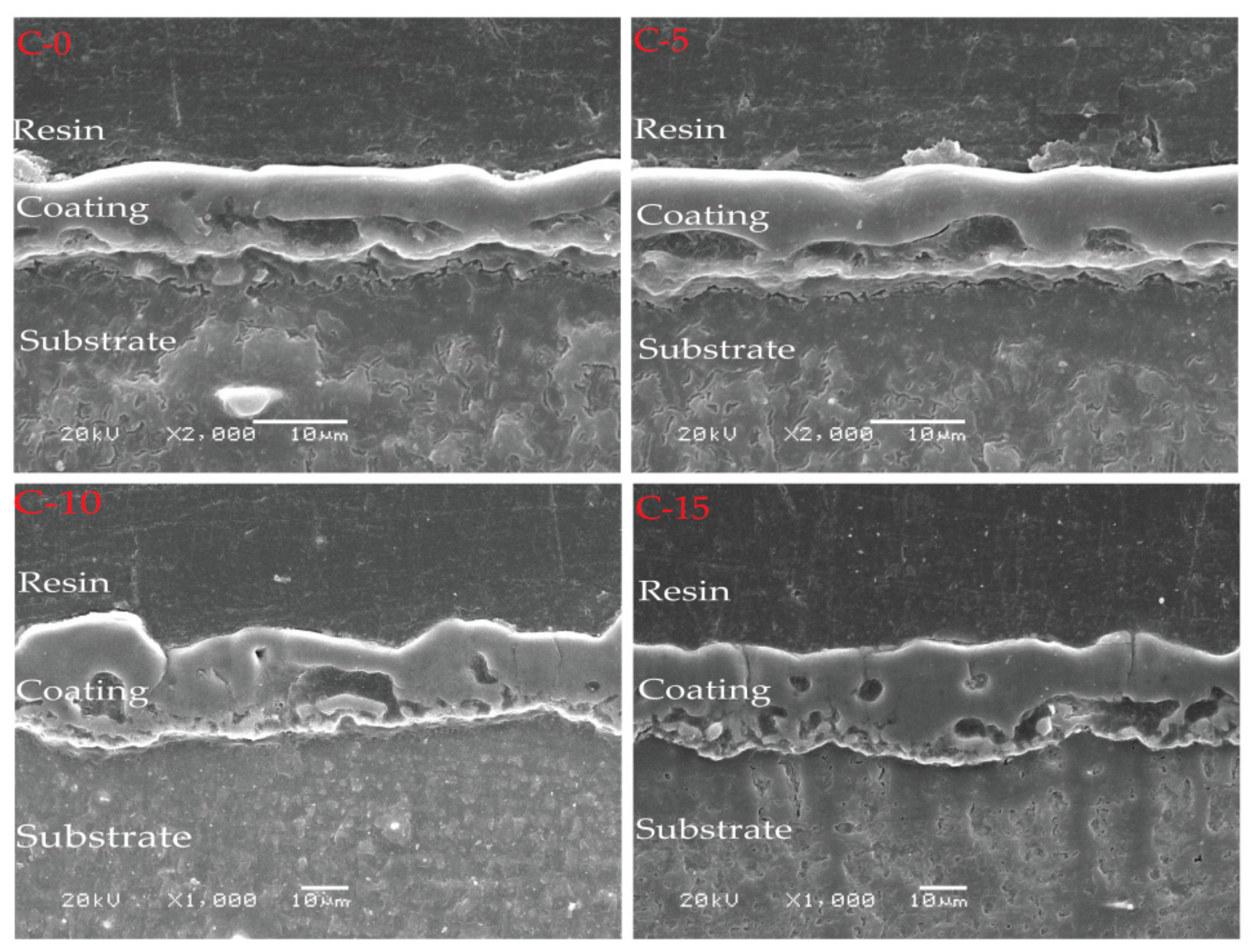
3.2. Surface and Cross-Section Morphologies

Figure 2 shows SEM images of the top surface of the plasma electrolytic oxidation film. Typical porous microstructures and molten matter were formed in the plasma electrolytic oxidation process. The KF additive in the electrolyte greatly influenced the surface morphologies of the PEO coatings. For samples C-0–C-15, upon increasing the concentration of KF, the electrolyte conductivity increased, the number of coating micropores decreased, and the pore diameters increased, all of which is consistent with previous studies [39]. Thus, the coatings obtained in the electrolyte with KF had much larger pore sizes than those obtained in the electrolyte without KF. This occurred because the electrolyte constituents contributed to the coating morphologies by changing the discharge behaviors [22]. In addition, some microcracks were evident on the surfaces of the coatings prepared from different fluorine contents solutions, which may have been initiated by the thermal stress during the rapid solidification of the melted oxide product in the discharge channel. This morphology and defect structure were closely related to the plasma characteristics [40].
Figure 3 and Table 2 show the cross-sectional structures of the PEO films obtained by SEM, as well as the thicknesses of the films. Based on the images for C-0 and C-5, when the KF in the electrolyte reached 5 g/L, the thickness of the fluorine-containing coating nearly doubled, which indicated that the growth rate of the film increased simultaneously and that KF played a very important role in promoting the growth of the coating. Furthermore, since the growth of the PEO coatings mainly occurs in the second stage of plasma electrolytic oxidation [41], the plasma electrolytic oxidation may have occurred earlier in the electrolyte containing fluorine. Presumably, due to addition of KF and the subsequent decrease in the arcing voltage, the energy consumed by the plasma electrolytic oxidation process was reduced, the surface spark of the sample was larger, and more breakdowns occurred simultaneously. This promoted the progress of the film-forming reaction and accelerated the growth of the film layer [39,42]. Further observations revealed that with the increase in the KF concentration, the adhesion between the coating and substrate was more compact, which may have been due to the easier adsorption of fluorine to the surface of the magnesium alloy to form a protective layer.

3.3. Elemental Composition

Figure 4 and Table 3 show the main components of the plasma electrolytic oxidation film. Without KF, the main elements of the film were O, Mg, and P. With the addition of KF, the fluorine content in the coating increased, and the oxygen and phosphorus content decreased.

3.4. Corrosion Resistance

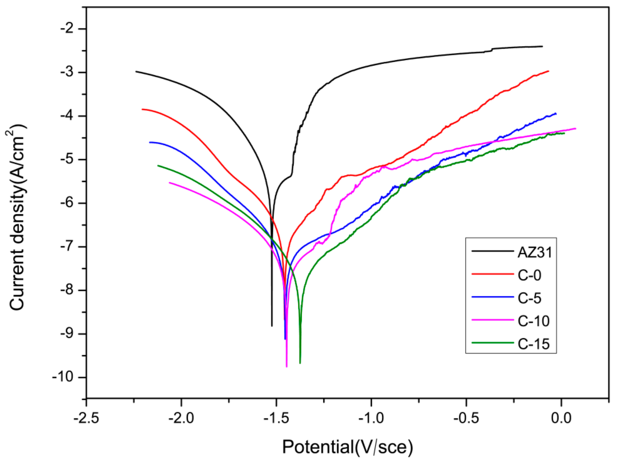
3.4.1. Electrochemical Measurements

Figure 5 shows the electrodynamic polarization curves of the samples treated with plasma electrolytic oxidation in SBF at room temperature, and Table 4 shows the corrosion current density (Icorr) and corrosion potential (Ecorr) obtained by fitting the polarization curves.
MgO (C-0) had more positive Ecorr (−1.448 ± 0.014 V) and lower Icorr ((1.397 ± 0.004) × 10−7 A/cm2) values than the AZ31 magnesium (−1.465 ± 0.003 V, (4.804 ± 0.080) × 10−6 A/cm2). However, the Ecorr (−1.375 ± 0.005 V) value of the MgF2 (C-15) was the most positive, and its Icorr value ((8.677 ± 0.023) × 10−9 A/cm2) was the lowest. Compared to the AZ31 substrate, the Ecorr of MgF2 (C-15) increased by approximately 90 mV, and the corrosion current density decreased by a factor of 1000. The corrosion resistance of AZ31 was improved by the plasma electrolytic oxidation treatment, especially with the fluorine electrolyte. This improvement was related to the decreased surface porosity and increased oxide layer thickness, as proven by the surface and cross-section SEM images. Moreover, the amount of the MgF2 phase was positively correlated with the corrosion resistance [43].
To further explore the corrosion characteristics of the coated and uncoated samples, impedance spectroscopy was conducted, and the resultant EIS plots and fitting equivalent circuits of the coated samples were shown in Figure 6, where Rs is the solution resistance, R1 is the resistance of the PEO coating paralleled with constant phase element (CPE)1, and R2 is the coating/substrate interface resistance in parallel with (CPE)2 [44]. The impedance parameters derived from the plots are given in Table 5. The polarization resistance, which is regarded as a measure of corrosion resistance, is calculated by R1 and R2, and the impedance of the spectrum is mainly determined by R2 [45,46]. Figure 6 shows that R1 and R2 increased with increasing KF content in the electrolyte, which indicates that the films had a better corrosion resistance with an increase in KF concentration, as is consistent with the results of Ecorr in Table 4. Meanwhile, the parameter values show that the resistance of the inner layer, R2, was generally much higher than that of the outer layer, R1, indicating much higher contribution of the inner layer than that of the outer layer to the overall corrosion resistance of the coatings.

3.4.2. Hydrogen Evolution Tests

Figure 7 shows the hydrogen evolution from the AZ31, C-0, C-5, C-10, and C-15 samples over a period of 14 days at a constant temperature (37 °C) in the SBF solution. The total hydrogen evolution of the bare AZ31 alloy reached 50.9 mL. In contrast, the amounts of hydrogen released by the C-0, C-5, C-10, and C-15 samples were 19.2, 11.9, 8.7, and 8.1 mL, respectively. As expected, the bare AZ31 alloy rapidly released copious amounts of hydrogen upon immersion. In addition, the degradation rate gradually decreased after seven days for the bare AZ31, which was attributed to a protective layer on the AZ31 alloy, consistent with previously reported results that the formation of corrosion product layer helps to reduce the corrosion rate of the matrix [47,48]. Furthermore, the PEO samples showed comparatively smaller volumes of released hydrogen, but the degradation rate gradually amplified after 10 days for C-0, because the layer was damaged and hydrogen was produced by the degradation of the freed AZ31 substrate. The other three groups were uniformly corroded, which indicated a high level of protection of the substrates by the coatings.

3.4.3. Long-Term Immersion Test

Figure 8 shows photographs of the five groups of samples after different soaking times. The AZ31 magnesium alloy group was corroded during the first day of immersion. However, no abnormalities were found on the surface of the coated group. Figure 8 shows that the C-0 sample suffered localized corrosion damage after immersion for 432 h; however, on the C-5 and C-10 samples, the corroded area appeared after immersion for 696 h in SBF. Finally, the slowest corrosion occurred in the C-15 group, which took 1488 h. In general, with the extension of the immersion time, the corrosion area increased, and the corrosion pits deepened. Finally, extensive corrosion occurred under both coatings. The results proved that the fluoride coating had better corrosion resistance than the fluoride-free coating, which was in good agreement with electrochemical analysis results.

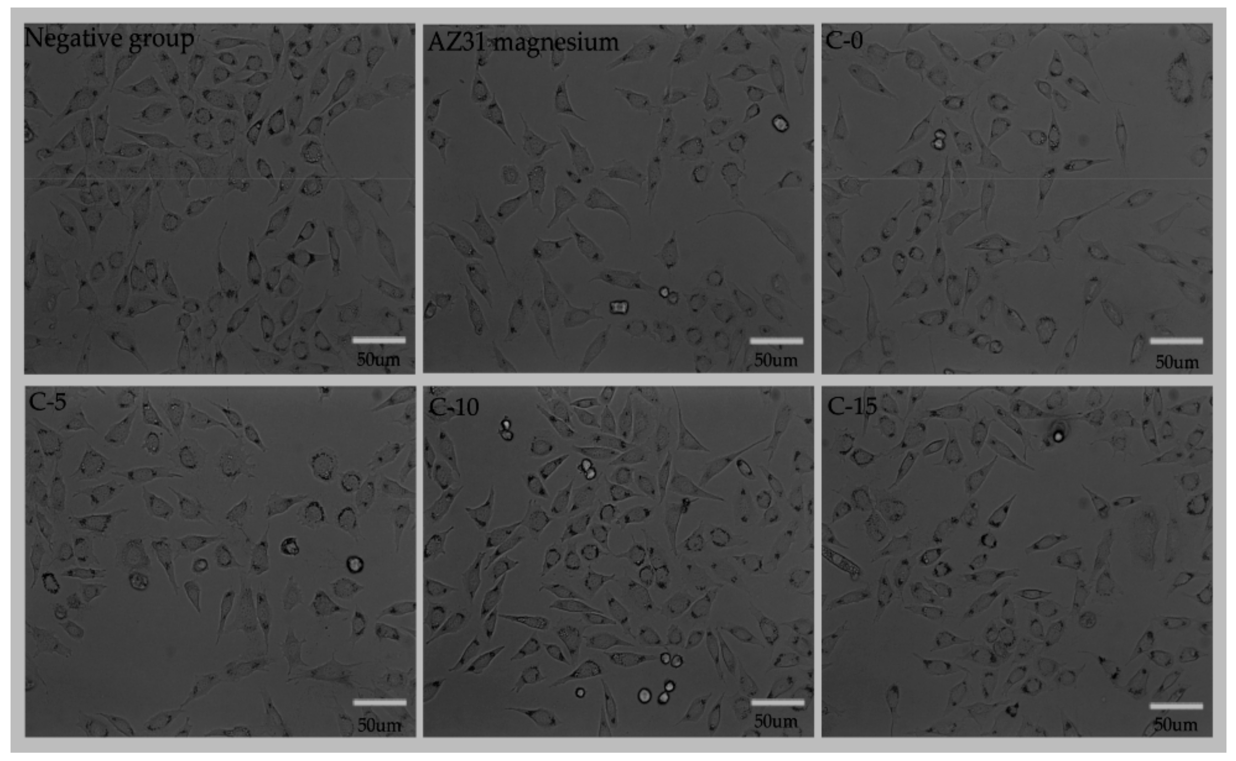
3.5. Cytotoxicity Test

An indirect assay was performed to evaluate the L-929 cell responses to the PEO-coated and uncoated AZ31 alloy samples. Figure 9 shows the changes in the cell viability with culture time. According to previous studies [49], AZ31 has a relatively good biocompatibility, which is a major reason that we selected AZ31 as the substrate. However, with the prolongation of culture time, the cell activity of the AZ31 magnesium alloy group decreased, possibly because the pH value was too high to be suitable for cell growth. Meanwhile, the cell viability of the coated group had a faster increase than the uncoated AZ31 alloy with increasing incubation time, showing a significantly higher value at every time point. With the addition of KF, the cytocompatibilities of the coatings showed a tendency to first rise and then fall, which indicated that too low or too high of a fluoride content was not suitable for cell growth and proliferation. However, the cells in the extracts of C-5, C-10, and C-15 showed no cytotoxicities, indicating that the protective coating was well tolerated by the L-929 cells. In particular, between one and five days, the cell survival rate of the C-10 group increased from 96% to 118%, which indicated that the coatings could promote the proliferation of the cells and exhibit a desirable cytocompatibility.
Cytotoxicity tests are important for evaluating the biocompatibility of a new biological material. The elements added to biomedical magnesium alloys should be carefully selected to ensure that there is no cytotoxicity. The interactions between the cells and materials can be monitored by L-929 cell co-cultures with the extracts of the alloys. Figure 10 shows the morphologies of the cells cultured in different extracts with inverted microscope images (20×). As shown in Figure 10, the density of the cells decreased for the AZ31 magnesium alloy, which suggested that the extracts of the coating may have inhibited cell growth. In addition, the cells of the C-5, C-10, and C-15 groups grew well, and the number of cells was similar to that of the negative group. These details are consistent with the cytotoxicity tests. Based on the above analysis, the extract of the C-10 group exhibited the best cytocompatibility.

4. Conclusions

Fluorine-free and fluorine coatings were successfully prepared by plasma electrolytic oxidation in a phosphate electrolyte on AZ31 magnesium alloy surfaces. The compositions, structures, corrosion behavior, and cytotoxicity of the coatings were studied, and the following conclusions were drawn:
(1).
The main component of the coating prepared in the fluorine-free electrolyte was MgO, and the coating components in the fluorine electrolyte were MgO and MgF2. Moreover, with increasing KF contents in the electrolyte, the porosity of the coating surface decreased and the coating thickness increased.
(2).
A corrosion resistance analysis showed that the corrosion resistance of the fluorine-containing plasma electrolytic oxidation film was superior to that without fluorine. Moreover, with increasing KF content in the electrolyte, corrosion resistance increased, which reduced the degradation rate of the AZ31 magnesium alloy.
(3).
In vitro cytotoxicity tests indicated that the cytocompatibility of the fluorine-containing coating was better than that of the fluorine-free coating and that the MgF2/AZ31 coating had no cytotoxic effect on the L-929 cells. In particular, with the increasing fluorine content, the cell proliferation was accelerated. However, after a certain amount of fluorine was added, it inhibited the cell growth. Thus, the proper fluoride content in the coating should be carefully determined to meet a balance between good corrosion resistance and cytocompatibility.

Author Contributions

Conceptualization, B.C., J.L.; Software, L.F.; Formal Analysis, L.F., L.Z., Y.Y. and Y.W.; Data Curation, L.F.; Writing—Original Draft Preparation, L.F.; Writing—Review and Editing, L.F., Y.Y., L.Z., Y.W., B.C. and J.L.

Funding

This research was funded by the Natural Foundation of Gansu Province, China (grant no. 1208RJZA236), the Key Technology Support Program of Gansu Province, China (grant no. 1604FKCA089), the Fundamental Research Funds for the Central Universities (grant no. lzujbky-2017-it48), and the Stomatology Scientific Research Support Funds of Hospital of Stomatology Lanzhou University (grant no. lzukqky-2019-y11).

Acknowledgments

We sincerely thank Yuming Qi and Zhenjun Peng from the State Key Laboratory of Solid Lubrication, Lanzhou Institute of Chemical Physics, Chinese Academy of Sciences, and Bowu Zhu from the Hospital of Stomatology Lanzhou University for the technical assistance during these studies. We also appreciate the valuable comments provided by other members of our laboratories. We thank LetPub (www.letpub.com) for its linguistic assistance during the preparation of this manuscript.

Conflicts of Interest

The authors declare no conflict of interest.

References

  1. Agarwal, S.; Curtin, J.; Duffy, B.; Jaiswal, S. Biodegradable magnesium alloys for orthopaedic applications: A review on corrosion, biocompatibility and surface modifications. Mater. Sci. Eng. C Mater. Biol. Appl. 2016, 68, 948–963. [Google Scholar] [CrossRef] [PubMed] [Green Version]
  2. Chen, Y.; Xu, Z.; Smith, C.; Sankar, J. Recent advances on the development of magnesium alloys for biodegradable implants. Acta Biomater. 2014, 10, 4561–4573. [Google Scholar] [CrossRef] [PubMed]
  3. Seal, C.K.; Vince, K.; Hodgson, M.A. Biodegradable surgical implants based on magnesium alloys—A review of current research. IOP Conf. Ser. Mater. Sci. Eng. 2009, 4, 012011. [Google Scholar] [CrossRef]
  4. Staiger, M.P.; Pietak, A.M.; Huadmai, J.; Dias, G. Magnesium and its alloys as orthopedic biomaterials: A review. Biomaterials 2006, 27, 1728–1734. [Google Scholar]
  5. Willbold, E.; Gu, X.; Albert, D.; Kalla, K.; Bobe, K.; Brauneis, M.; Janning, C.; Nellesen, J.; Czayka, W.; Tillmann, W.; et al. Effect of the addition of low rare earth elements (lanthanum, neodymium, cerium) on the biodegradation and biocompatibility of magnesium. Acta Biomater. 2015, 11, 554–562. [Google Scholar]
  6. Witte, F.; Fischer, J.; Nellesen, J.; Crostack, H.A.; Kaese, V.; Pisch, A.; Beckmann, F.; Windhagen, H. In vitro and in vivo corrosion measurements of magnesium alloys. Biomaterials 2006, 27, 1013–1018. [Google Scholar] [CrossRef]
  7. Zhao, D.; Witte, F.; Lu, F.; Wang, J.; Li, J.; Qin, L. Current status on clinical applications of magnesium-based orthopaedic implants: A review from clinical translational perspective. Biomaterials 2017, 112, 287–302. [Google Scholar]
  8. Saris, N.E.L.; Mervaala, E.; Karppanen, H.; Khawaja, J.A.; Lewenstam, A. Magnesium: An update on physiological, clinical and analytical aspects. Clin. Chim. Acta 2000, 294, 1–26. [Google Scholar]
  9. Trumbo, P.; Schlicker, S.; Yates, A.A.; Poos, M. Dietary Reference Intakes for Energy, Carbohydrate, Fiber, Fat, Fatty Acids, Cholesterol, Protein and Amino Acids. J. Acad. Nutr. Diet. 2002, 102, 1621. [Google Scholar]
  10. Dorozhkin, S.V. Calcium orthophosphate coatings on magnesium and its biodegradable alloys. Acta Biomater. 2014, 10, 2919–2934. [Google Scholar] [CrossRef]
  11. Sezer, N.; Evis, Z.; Kayhan, S.M.; Tahmasebifar, A.; Koç, M. Review of magnesium-based biomaterials and their applications. J. Magnes. Alloys 2018, 6, 23–43. [Google Scholar] [CrossRef]
  12. Song, G.L.; Atrens, A. Corrosion Mechanisms of Magnesium Alloys. Adv. Eng. Mater. 2010, 1, 11–33. [Google Scholar] [CrossRef]
  13. Waizy, H.; Seitz, J.-M.; Reifenrath, J.; Weizbauer, A.; Bach, F.-W.; Meyer-Lindenberg, A.; Denkena, B.; Windhagen, H. Biodegradable magnesium implants for orthopedic applications. J. Mater. Sci. 2012, 48, 39–50. [Google Scholar] [CrossRef]
  14. Tian, P.; Peng, F.; Wang, D.; Liu, X. Corrosion behavior and cytocompatibility of fluoride-incorporated plasma electrolytic oxidation coating on biodegradable AZ31 alloy. Regen. Biomater. 2017, 4, 1–10. [Google Scholar] [CrossRef] [Green Version]
  15. Gao, J.H.; Shi, X.Y.; Yang, B.; Hou, S.S.; Meng, E.C.; Guan, F.X.; Guan, S.K. Fabrication and characterization of bioactive composite coatings on Mg–Zn–Ca alloy by MAO/sol–gel. J. Mater. Sci. Mater. Med. 2011, 22, 1681–1687. [Google Scholar] [CrossRef]
  16. Zhu, B.; Xu, Y.; Sun, J.; Yang, L.; Guo, C.; Liang, J.; Cao, B. Preparation and Characterization of Aminated Hydroxyethyl Cellulose-Induced Biomimetic Hydroxyapatite Coatings on the AZ31 Magnesium Alloy. Metals 2017, 7, 214. [Google Scholar] [CrossRef] [Green Version]
  17. Zhu, B.; Wang, S.; Wang, L.; Yang, Y.; Liang, J.; Cao, B. Preparation of Hydroxyapatite/Tannic Acid Coating to Enhance the Corrosion Resistance and Cytocompatibility of AZ31 Magnesium Alloys. Coatings 2017, 7, 105. [Google Scholar] [CrossRef] [Green Version]
  18. Wang, L.; Zhou, J.; Liang, J.; Chen, J. Microstructure and corrosion behavior of plasma electrolytic oxidation coated magnesium alloy pre-treated by laser surface melting. Surf. Coat. Technol. 2012, 206, 3109–3115. [Google Scholar] [CrossRef]
  19. Jiang, H.B.; Kim, Y.K.; Ji, J.H.; Park, I.S.; Bae, T.S.; Lee, M.H. Surface modification of anodized Mg in ammonium hydrogen fluoride by various voltages. Surf. Coat. Technol. 2014, 259, 310–317. [Google Scholar] [CrossRef]
  20. Wang, S.; Fu, L.; Nai, Z.; Liang, J.; Cao, B. Comparison of Corrosion Resistance and Cytocompatibility of MgO and ZrO2 Coatings on AZ31 Magnesium Alloy Formed via Plasma Electrolytic Oxidation. Coatings 2018, 8, 441. [Google Scholar] [CrossRef] [Green Version]
  21. Dou, J.; Chen, Y.; Chi, Y.; Li, H.; Gu, G.; Chen, C. Preparation and characterization of a calcium-phosphate-silicon coating on a Mg-Zn-Ca alloy via two-step micro-arc oxidation. Phys. Chem. Chem. Phys. 2017, 19, 15110–15119. [Google Scholar] [CrossRef]
  22. Jia, Z.J.; Li, M.; Liu, Q.; Xu, X.C.; Cheng, Y.; Zheng, Y.F.; Xi, T.F.; Wei, S.C. Micro-arc oxidization of a novel Mg–1Ca alloy in three alkaline KF electrolytes: Corrosion resistance and cytotoxicity. Appl. Surf. Sci. 2014, 292, 1030–1039. [Google Scholar] [CrossRef]
  23. Rehman, Z.U.; Shin, S.H.; Hussain, I.; Koo, B.H. Investigation of hybrid PEO coatings on AZ31B magnesium alloy in alkaline K2ZrF6–Na2SiO3 electrolyte solution. Prot. Met. Phys. Chem. 2017, 53, 495–502. [Google Scholar] [CrossRef]
  24. Sankara Narayanan, T.S.N.; Park, I.S.; Lee, M.H. Tailoring the composition of fluoride conversion coatings to achieve better corrosion protection of magnesium for biomedical applications. J. Mater. Chem. B 2014, 2, 3365–3382. [Google Scholar] [CrossRef]
  25. Khiabani, A.B.; Ghanbari, A.; Yarmand, B.; Zamanian, A.; Mozafari, M. Improving corrosion behavior and in vitro bioactivity of plasma electrolytic oxidized AZ91 magnesium alloy using calcium fluoride containing electrolyte. Mater. Lett. 2018, 212, 98–102. [Google Scholar] [CrossRef]
  26. Němcová, A.; Skeldon, P.; Thompson, G.E.; Pacal, B. Effect of fluoride on plasma electrolytic oxidation of AZ61 magnesium alloy. Surf. Coat. Technol. 2013, 232, 827–838. [Google Scholar] [CrossRef]
  27. Mousny, M.; Omelon, S.; Wise, L.; Everett, E.T.; Dumitriu, M.; Holmyard, D.P.; Banse, X.; Devogelaer, J.P.; Grynpas, M.D. Fluoride effects on bone formation and mineralization are influenced by genetics. Bone 2008, 43, 1067–1074. [Google Scholar] [CrossRef] [Green Version]
  28. Yan, T.; Tan, L.; Xiong, D.; Liu, X.; Zhang, B.; Yang, K. Fluoride treatment and in vitro corrosion behavior of an AZ31B magnesium alloy. Mater. Sci. Eng. C 2010, 30, 740–748. [Google Scholar] [CrossRef]
  29. Lee, H.J.; Park, Y.J. Surface modification of Li[Li0.2Ni0.2Mn0.6]O2 nanoparticles with polydopamine-assisted MgF2 coating. Mater. Res. Bull. 2014, 58, 169–173. [Google Scholar] [CrossRef]
  30. Liu, X.; Zhen, Z.; Liu, J.; Xi, T.; Zheng, Y.; Guan, S.; Zheng, Y.; Cheng, Y. Multifunctional MgF2/Polydopamine Coating on Mg Alloy for Vascular Stent Application. J. Mater. Sci. Technol. 2015, 31, 733–743. [Google Scholar] [CrossRef]
  31. Riaz, U.; Rahman, Z.U.; Asgar, H.; Shah, U.; Shabib, I.; Haider, W. An insight into the effect of buffer layer on the electrochemical performance of MgF2 coated magnesium alloy ZK60. Surf. Coat. Technol. 2018, 344, 514–521. [Google Scholar] [CrossRef]
  32. Yu, W.; Zhao, H.; Ding, Z.; Zhang, Z.; Sun, B.; Shen, J.; Chen, S.; Zhang, B.; Yang, K.; Liu, M.; et al. In vitro and in vivo evaluation of MgF2 coated AZ31 magnesium alloy porous scaffolds for bone regeneration. Colloids Surf. B. Biointerfaces 2017, 149, 330–340. [Google Scholar] [CrossRef]
  33. Marc, B.; Jacques, L. Can bioactivity be tested in vitro with SBF solution? Biomaterials 2009, 30, 2175–2179. [Google Scholar]
  34. Bakhsheshi-Rad, H.R.; Hamzah, E.; Kasiri-Asgarani, M.; Jabbarzare, S.; Iqbal, N.; Kadir, M.R.A. Deposition of nanostructured fluorine-doped hydroxyapatite–polycaprolactone duplex coating to enhance the mechanical properties and corrosion resistance of Mg alloy for biomedical applications. Mater. Sci. Eng. C 2016, 60, 526–537. [Google Scholar] [CrossRef]
  35. ISO 10993-12:2007 Biological Evaluation of Medical Devices—Part 12: Sample Preparation and Reference Materials; ISO: Geneva, Switzerland, 2007.
  36. Li, Z.; Shizhao, S.; Chen, M.; Fahlman, B.D.; Debao, L.; Bi, H. In vitro and in vivo corrosion, mechanical properties and biocompatibility evaluation of MgF2-coated Mg-Zn-Zr alloy as cancellous screws. Mater. Sci. Eng. C Mater. Biol. Appl. 2017, 75, 1268–1280. [Google Scholar] [CrossRef]
  37. Tang, M.; Liu, H.; Li, W.; Zhu, L. Effect of zirconia sol in electrolyte on the characteristics of microarc oxidation coating on AZ91D magnesium. Mater. Lett. 2011, 65, 413–415. [Google Scholar] [CrossRef]
  38. Mihailescu, N.; Stan, G.E.; Duta, L.; Chifiriuc, M.C.; Bleotu, C.; Sopronyi, M.; Luculescu, C.; Oktar, F.N.; Mihailescu, I.N. Structural, compositional, mechanical characterization and biological assessment of bovine-derived hydroxyapatite coatings reinforced with MgF2 or MgO for implants functionalization. Mater. Sci. Eng. C 2016, 59, 863–874. [Google Scholar] [CrossRef]
  39. Wang, L.; Chen, L.; Yan, Z.; Wang, H.; Peng, J. Effect of potassium fluoride on structure and corrosion resistance of plasma electrolytic oxidation films formed on AZ31 magnesium alloy. J. Alloys Compd. 2009, 480, 469–474. [Google Scholar] [CrossRef]
  40. Nashrah, N.; Kamil, M.P.; Yoon, D.K.; Kim, Y.G.; Ko, Y.G. Formation mechanism of oxide layer on AZ31 Mg alloy subjected to micro-arc oxidation considering surface roughness. Appl. Surf. Sci. 2019, 143772. [Google Scholar] [CrossRef]
  41. Zhao, L.; Cui, C.; Wang, Q.; Bu, S. Growth characteristics and corrosion resistance of micro-arc oxidation coating on pure magnesium for biomedical applications. Corros. Sci. 2010, 52, 2228–2234. [Google Scholar] [CrossRef]
  42. Guo, H.F.; An, M.Z. Growth of ceramic coatings on AZ91D magnesium alloys by micro-arc oxidation in aluminate–fluoride solutions and evaluation of corrosion resistance. Appl. Surf. Sci. 2005, 246, 229–238. [Google Scholar]
  43. Jiang, H.B.; Wu, G.; Lee, S.-B.; Kim, K.-M. Achieving controllable degradation of a biomedical magnesium alloy by anodizing in molten ammonium bifluoride. Surf. Coat. Technol. 2017, 313, 282–287. [Google Scholar] [CrossRef]
  44. Wang, L.; Zhou, J.; Liang, J.; Chen, J. Corrosion Mechanism of Plasma Electrolytic Oxidation Coated Magnesium Alloy with Laser Surface Melting Pretreatment. J. Electrochem. Soc. 2014, 161, C20–C24. [Google Scholar]
  45. Shi, P.; Niu, B.; Shanshan, E.; Chen, Y.; Li, Q. Preparation and characterization of PLA coating and PLA/MAO composite coatings on AZ31 magnesium alloy for improvement of corrosion resistance. Surf. Coat. Technol. 2015, 262, 26–32. [Google Scholar]
  46. Zuo, Y.; Li, T.; Yu, P.; Zhao, Z.; Chen, X.; Zhang, Y.; Chen, F. Effect of graphene oxide additive on tribocorrosion behavior of MAO coatings prepared on Ti6Al4V alloy. Appl. Surf. Sci. 2019, 480, 26–34. [Google Scholar] [CrossRef]
  47. Rojaee, R.; Fathi, M.; Raeissi, K. Controlling the degradation rate of AZ91 magnesium alloy via sol-gel derived nanostructured hydroxyapatite coating. Mater. Sci. Eng. C Mater. Biol. Appl. 2013, 33, 3817–3825. [Google Scholar]
  48. Tian, P.; Xu, D.; Liu, X. Mussel-inspired functionalization of PEO/PCL composite coating on a biodegradable AZ31 magnesium alloy. Colloids Surf. B. Biointerfaces 2016, 141, 327–337. [Google Scholar] [CrossRef]
  49. Iglesias, C.; Bodelon, O.G.; Montoya, R.; Clemente, C.; Garcia-Alonso, M.C.; Rubio, J.C.; Escudero, M.L. Fracture bone healing and biodegradation of AZ31 implant in rats. Biomed. Mater. 2015, 10, 025008. [Google Scholar]
Figure 1. X-ray diffraction (XRD) patterns of plasma electrolytic oxidation (PEO) coatings on the AZ31 Mg alloy.
Coatings 09 00826 g001
Figure 2. Surface morphologies of PEO coatings on the AZ31 Mg alloy.
Coatings 09 00826 g002
Figure 3. Cross-sectional images of all PEO coatings.
Coatings 09 00826 g003
Figure 4. Elemental compositions of C-0, C-5, C-10, and C-15, analyzed by energy-dispersive X-ray spectrometry (EDS).
Coatings 09 00826 g004
Figure 5. Potentiodynamic polarization curves for the samples in simulated body fluid (SBF) at room temperature.
Coatings 09 00826 g005
Figure 6. Nyquist curve and fitting equivalent circuits for samples in SBF at room temperature.
Coatings 09 00826 g006
Figure 7. Hydrogen evolution of AZ31, C-0, C-5, C-10, and C-15 samples in SBF for 14 days.
Coatings 09 00826 g007
Figure 8. Immersion test results for the AZ31 Mg alloy, C-0, C-5, C-10, and C-15.
Coatings 09 00826 g008
Figure 9. Absorbance of the negative and samples.
Coatings 09 00826 g009
Figure 10. Inverted microscope images (20×) for the L-929 cells cultured with extracts originating from the negative group, AZ31 magnesium, C-0, C-5, C-10, and C-15 for three days.
Coatings 09 00826 g010
Table 1. Composition and concentration of MAO electrolytes in each group.
Group\Electrolytes(NaPO3)6 (g/L)NaOH (g/L)KF (g/L)
C-0320
C-5325
C-103210
C-153215
Table 2. Thicknesses of coating surfaces (mean ± SD).
GroupC-0C-5C-10C-15
Thickness (µm)5.84 ± 2.379.49 ± 1.9625.61 ± 3.2627.83 ± 3.51
Table 3. Elemental compositions of the coating surfaces (mean ± SD).
Elements (wt %)MgOFPNa
C-033.00 ± 0.1246.66 ± 0.32018.38 ± 0.041.18 ± 0.10
C-537.80 ± 0.0238.70 ± 0.177.67 ± 0.0912.66 ± 0.352.66 ± 0.13
C-1035.86 ± 0.0232.96 ± 0.2815.48 ± 0.0410.20 ± 0.022.69 ± 0.04
C-1535.20 ± 0.0425.61 ± 0.1425.74 ± 0.077.90 ± 0.112.05 ± 0.04
Table 4. Corrosion potential (Ecorr) and corrosion current density (Icorr) of the samples in SBF (mean ± SD).
SamplesEcorr (V vs. SCE)Icorr (A/cm2)
AZ31−1.465 ± 0.003(4.804 ± 0.080) × 10-6
C-0−1.448 ± 0.014 (1.397 ± 0.004) × 10−7 *
C-5−1.457 ± 0.002 *(2.419 ± 0.317) × 10−8 *
C-10−1.393 ± 0.006 *(3.151 ± 0.071) × 10−8 *
C-15−1.375 ± 0.005 *(8.677 ± 0.023) × 10−9 *
*The results of the group had significant differences from the AZ31 group (p < 0.05).
Table 5. Fitting results of the electrochemical impedance spectroscopy (EIS) plots of the coated samples in the SBF solution.
SamplesRs (Ω·cm2)CPE1R1 (Ω·cm2)CPE2R2 (Ω·cm2)
C-00.013.52 × 10−826935.90 × 10−61.98 × 10⁴
C-50.011.94 × 10−827214.05 × 10−62.81 × 10⁴
C-100.011.68 × 10−842382.81 × 10−63.02 × 10⁴
C-150.012.08 × 10−870122.83 × 10−73.80 × 10⁴

