Abstract
WC-10Ni + AgCuTi composite coating with WC mass fraction of 40% was prepared on the copper surface by vacuum brazing. The brazing temperatures were 830 °C, 860 °C, 890 °C, and 920 °C. The microstructure, interface structure, and hardness of the coating section were studied. The results showed that the composite coatings obtained at different brazing temperatures were better combined. As the brazing temperature increased, the Ni transition layer wrapped around the WC gradually decreased until it disappeared. The brazing seam gradually thickened, the reaction between the coating and the substrate became more and more intense, and more and more Cu was formed on both sides of the brazing seam. Scanning analysis of the interface between the coating and the substrate showed that the elements W and Ti hardly diffused into the brazing seam and the substrate, and the elements Ag and Cu diffused into the substrate. Finally, the interface between the brazing seam and the substrate was metallurgically bonded. The Vickers hardness results and bond strength results of the composite coatings show that the mechanical properties of the coatings are best when the brazing temperature is 890 °C.
1. Introduction
Copper and copper alloys have high electrical and thermal conductivity, good corrosion resistance, and wear resistance, and are widely used in electric power, electrical, mechanical, and other industrial fields, such as continuous casting molds, blast furnace tuyeres, lead frames, electric vacuum devices, and power rails. Although pure copper has excellent electrical and thermal conductivity, its low strength and poor wear resistance can not fully meet industrial applications. When operating under wear conditions, materials are prone to failure, and their application scenarios are limited. Therefore, with the rapid development of the manufacturing industry, higher requirements are imposed on the conditions of use of copper alloy parts, and related surface engineering techniques have emerged to achieve enhanced surface strength and maintain high electrical conductivity of the copper alloy as a whole [1,2].
According to the process characteristics, pure copper surface modification technology could be divided into two categories. The first type is to add a coating on the surface of the substrate, including coating, laser cladding, thermal spraying, surfacing, vapor deposition, etc. The other type is to change the surface properties of the substrate by means of processing reinforcement, including shot peening, high energy beam surface modification, and the like [3,4]. Gao Jiacheng et al. [5] prepared an Al2O3-based ceramic coating on the surface of pure copper by oxyacetylene flame spraying and remelting. The experimental results showed that the coating could enhance the bonding strength, heat resistance, and alkali resistance of copper. There were practical applications in industrial production. Gao Fei et al. [6] used a spark deposition technique to deposit a Ni/cermet coating on copper. The results showed that under the reasonable deposition conditions, a good metallurgical bond could be obtained by depositing a Ni-ceramic coating on the copper, and the hardness of the coating gradually decreased from the surface of the coating to the inside. Tian Fengjie et al. [7] prepared the Ni60A coating by laser cladding on a pure copper substrate, and its hardness and corrosion resistance were significantly improved compared with the copper substrate. As a new surface coating technology, vacuum cladding has received extensive attention in recent years [8]. The prepared coating samples have no stress concentration phenomenon, the base material is basically free of deformation, and there is no oxidation under vacuum protection. Also, the bond between the coating and the substrate is a metallurgical bonding and the bonding strength is high. Huang Liuxian et al. [9] used a vacuum cladding method to prepare a layer of WC and nickel-chromium auto-dissolving alloy composite coating on the surface of 1045 steel, and the cladding temperature was 1150 °C. The results showed that the microhardness and wear resistance of the hard layer and the diffusion layer were decreasing, and the microhardness distribution of the hard layer was relatively uniform.
In this paper, vacuum cladding technology and flexible “coated cloth” technology were combined to prepare WC-10Ni + AgCuTi composite coating on copper surfaces [10,11]. The microstructure and properties of WC-10Ni + AgCuTi composite coating were studied under different brazing temperature. The purpose is to improve the hardness and wear resistance of the surface of the part and to avoid the problems of poor bonding performance, large residual stress, and high input cost when preparing the composite coating by thermal spraying, surfacing, and laser cladding.
2. Materials and Methods
The composite coating material used in the experiment consisted of WC-10Ni powder of 11 μm to 45 μm, AgCuTi solder of 30 μm to 45 μm, and a trace amount of binder. Among them, WC-10Ni powder was produced from Chengdu Ketailong Alloy Co., Ltd., (Chengdu, China) and AgCuTi was produced from Shanghai Dahua solder (Shanghai, China). Figure 1 shows the microscopic morphology of AgCuTi powder.
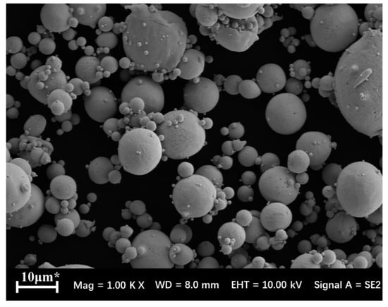
Figure 1.
Particles of Ag68.8Cu26.7Ti4.5 powder (SEM).
WC-10Ni powder, AgCuTi solder, and binder were weighed on an electronic balance with a mass ratio of 4:5:1. After stirring and mixing, it was repeatedly rolled into a tape shape by a roll mill to a thickness of 1 mm to prepare a composite coating material. As shown in Figure 2, this composite coating can be cut and folded at will. The substrate was T2 copper plate, and the size was 30 mm × 30 mm × 3 mm. WZB-20 vacuum brazing furnace of Zhongshan Kaixuan Vacuum Technology Engineering Co., Ltd. (Zhongshan, China) was selected. The surface of the copper plate was ground with 400#, 600#, 1000#, 1200#, 1500# sandpaper, and then the copper plate was ultrasonically cleaned in an acetone solution for 15 min, and finally taken out and dried. Before the experiment, the WC-10Ni + AgCuTi composite coating/copper plate was placed in the brazing furnace in the assembly sequence. Vacuum brazing was carried out at brazing temperatures of 830 °C, 860 °C, 890 °C, and 920 °C with a holding time of 30 min. The short holding time was not conducive to the combination of the brazing material and the matrix. The holding time was too long, and the brazing material was easily lost, which was not conducive to the reaction. Further, the heating rate was 10 °C/min, and the cooling rate was 5 °C/min in the experiment.
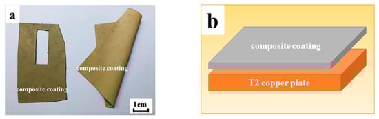
Figure 2.
(a) Cloth-like composite coating; (b) Pre-weld assembly sequence.
After the brazing was completed, a 10 mm × 10 mm metallographic sample was cut from the sample with a PROTO MAX waterjet. According to the principle of coarse to fine, the sample was water-milled step by step until the surface of the sample was consistent. The water-milled sample was then polished with a 0.5 μm synthetic diamond paste to remove fine scratches on the surface of the sample to obtain a smooth mirror. Finally, the MSD400E inverted metallographic microscope was used to observe the macroscopic morphology of the coating section. Punctual and linear elemental analyses were performed on the characteristic areas of the coating cross-section with a JSM-6480 scanning electron microscope with an energy spectrum analyzer (Kyoto, Japan). The surface of the coated sample was analyzed by Shimadzu XRD-6000 X-ray diffractometer (Tokyo, Japan). The continuous scanning mode was used with a scanning rate of 9°/min and a diffraction angle range of 10°–90°. The hardness of the sample was tested by automatic microhardness tester. Figure 3 is a schematic diagram of the Vickers hardness striking position of the composite coating section, taking points 1–3 on the copper substrate, taking 4–5 on the brazing seam and taking the point 6–10 on the coating. The test load was 300 g, and the load time was 20 s. The coating at each brazing temperature was tested three times and then averaged. The bonding strength of the coating to the substrate was tested using a CMT5205 electronic universal testing machine (Zhuhai, China) and a self-designed shearing fixture, and the coating was tested five times at each temperature.
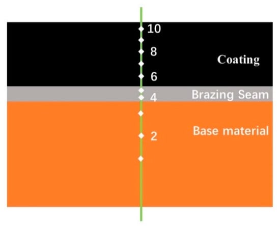
Figure 3.
Schematic diagram of the hardness position of the composite coating.
3. Result and Discussion
3.1. Microstructure and Structure Analysis of the Coating Section
Figure 4 shows the cross-section of the sample at four different brazing temperatures. The orange area below was a copper substrate, the white area in the middle was a brazed joint, and the black area above was a WC-10Ni + AgCuTi composite coating. The composite coating consists of alternating soft and hard materials composed of reinforcing particles WC-10Ni on the AgCuTi brazing filler metal substrate. The hard phase WC particles were evenly distributed, and there was no phenomenon of aggregation or direct contact with the copper substrate. The entire section of the microscopic morphology can be divided into three different interfaces. The first interface was the interface between the braze and the copper substrate. The AgCuTi solder can wet the copper base material well, and the liquid solder and the substrate dissolved each other to form a brazing seam. At 830 °C, the silver in the solder hardly diffused into the substrate. As the temperature increased, the brazing seam gradually widened. More and more silver diffused into the copper substrate, and the copper in the substrate slowly diffused. In the brazing seam, it grew upward like a stalagmite, and it was getting bigger and bigger, more and more. The second interface was the interface between the coating and the brazing seam. As the temperature increased, more and more copper was on the interface. The third interface was the interface between the hard phase particles WC-10Ni and the AgCuTi solder. The AgCuTi solder wetted the substrate and also wet the reinforcing particles WC-10Ni.
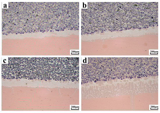
Figure 4.
Microscopic morphology of composite coatings at different temperatures (a) Micro-morphology of composite coating at a brazing temperature of 830 °C; (b) Micro-morphology of composite coating at a brazing temperature of 860 °C; (c) Micro-morphology of composite coating at a brazing temperature of 890 °C; (d) Micro-morphology of composite coating at a brazing temperature of 920 °C.
As shown in Figure 5, it can be seen that there was a wide and narrow gray area around the WC particles, which was a diffusion layer. As the brazing temperature increased, the transition layer became narrower and narrower. At 920 °C, the transition layer almost disappeared. The gray area wrapped around the WC particles was Ni. When the brazing temperature reached 780 °C, Ag–Cu melted, and the temperature continued to rise. The Ti element dissolved in the liquid phase and accumulated around the WC-10Ni particles, and reacted with the W-coated Ni to form a Ni–Ti compound. As the reaction progressed, part of the Ti entered the inside of the WC particles during the reaction with Ni, and the C element in the WC particles also diffused outward across the interface, and C reacted with Ti to form TiC. Therefore, the Ni wrapped outside the WC particles was continuously consumed, and the higher the brazing temperature, the more the reaction, until the brazing temperature reached 920 °C, Ni was almost completely consumed, and the gray region was substantially disappeared. From this point of view, the copper substrate and the composite coating had a good bond at the interface of the brazing joint, and the bonding between the reinforcing particles WC and the AgCuTi brazing filler metal was good. The combination of the WC-10Ni/AgCuTi composite coating with the substrate was a typical metallurgical bond.
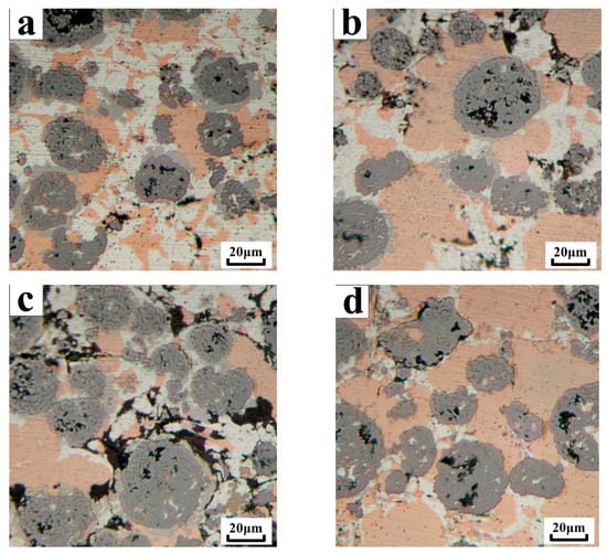
Figure 5.
Transition layer changes of WC reinforcing particles and AgCuTi solder at different temperatures (a) Transition layer at a brazing temperature of 830 °C; (b) Transition layer at a brazing temperature of 860 °C; (c) Transition layer at a brazing temperature of 890 °C; (d) Transition layer at a brazing temperature of 920 °C.
3.2. Internal Microstructure and Microstructure Analysis of Coating
The test results of different phase compositions inside the coating and inside the brazing joint by EDS spectroscopy are shown in Table 1. In Figure 6a, the hard particle A region mainly contained W and a small amount of Ag, Cu, Ti, which indicated that the brazing material smoothly entered the inside of the WC particles and wetted the WC particles. The outer layer B region of the hard particles was rich in Ti and Ni, which indicated that the active element Ti aggregated around the WC particles reacted with the W-coated Ni to form a Ni-Ti compound, and was partially in the Ti and WC particles. The C element reacted to form TiC, which connected the solder to the hard phase. Figure 6a C, D area was mainly Ag-based solid solution and Cu-based solid solution, only a trace of Ti. The E and F regions of Figure 6b were mainly Ag-based solid solution and Cu-based solid solution, and a trace amount of W, which also indicated that the brazing material successfully entered the inside of the WC particles and wrapped the WC particles. The above showed that during vacuum brazing, some of the WC particles began to dissolve at high temperature, and diffused and reacted with the liquid solder. The H, K regions in the middle of the braze joint in Figure 6c were alloy regions rich in Ag and Cu. The brazing gold area was mainly composed of an off-white H zone and a dark gray K zone. The energy spectrum analysis showed that the two solid solution components were Cu-rich Cu-based solid solution and Ag-rich Ag-based solid solution. The two solid solution structures were distributed in the eutectic form in the braze.

Table 1.
Element distribution results at each point in Figure 6 (at.%).
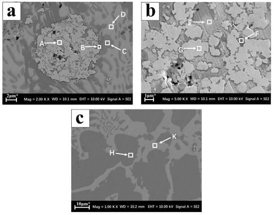
Figure 6.
Coating microstructure (a) Inside the coating; (b) WC enhances the interior of the particle; (c) Brazing seam interior.
The microstructure of the coating and substrate reaction layers at four different brazing temperatures are shown in Figure 7. The interface between the four coatings and the base metal was well wetted, the microstructure of the brazing joint was dense and uniform, and the WC particles were well wetted with the brazing filler metal. The element line scan was performed at the line segments L1, L2, L3, and L4 in the figure by EDS, and the elements at the interface were distributed, as shown in Figure 7b,d,f,h. It was found that the elements W and Ti hardly diffused into the brazing seam and the substrate, and the elements Ag and Cu diffused toward the substrate. Based on the above analysis, the interface between the brazing seam and the substrate was metallurgically bonded, and the brazing seam mainly carried the combination of the coating and the substrate. As the brazing temperature increased, Cu near the side of the hard layer and Cu near the side of the substrate diffused more, so excessive brazing temperature was not conducive to the metallurgical reaction between the coating and the substrate.
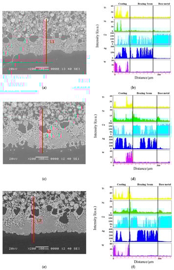
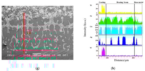
Figure 7.
Element distribution a brazed interfaces (a) Line scanning position of the 830 °C coating; (b) Element distribution of the 830 °C coating; (c) Line scanning position of the 860 °C coating; (d) Element distribution of the 860 °C coating; (c) Brazing seam interior; (e) Line scanning position of the 890 °C coating; (f) Element distribution of the 890 °C coating; (g) Line scanning position of the 920 °C coating; (h) Element distribution of the 920 °C coating.
The process of depositing WC-10Ni/AgCuTi composite coating on the copper surface could be divided into three stages. In the first stage, liquid phase formation and particle rearrangement. When the heating temperature exceeded the melting point of the AgCuTi solder, the solder was gradually melted into a liquid phase as a binder phase, and the cemented carbide was suspended in the liquid solder as a reinforcing phase, and the liquid solder relies on capillary force formed between the gaps of the particles. And its own flow filled the pores between the particles. Finally, the WC particles reached a stable distribution and alignment under the combined action of gravity, capillary force, and viscous flow. In the second stage, the solder element diffused toward the substrate and reacted to form a reaction layer. When the heating temperature was between the melting point of the brazing filler metal, and the brazing temperature, the liquid brazing material diffused to the coating and the substrate to form a brazing seam, and the brazing seam played a major connecting role. Due to the difference in concentration between the liquid phase and the alloying elements in the substrate, elemental diffusion occurred at the interface, which was accompanied by the first stage. In the third stage, a composite coating was formed. As the brazing temperature decreased, the hard phase and the brazing material condensed to form a composite coating, and a metallurgical bond was formed between the coating and the substrate.
As shown in Figure 7, the brazing joint was mainly composed of an Ag-based solid solution and a Cu-based solid solution, and the two types of solid solution structures were distributed in a joint in a typical eutectic form. One was a lamellar eutectic structure, and the other was an anomalous eutectic structure. The heating rate of this test was 10 °C/min, but after holding the brazing temperature for 30 min, the set cooling rate was only 5 °C/min, which was very close to the equilibrium solidification conditions. In addition, the Ag–Cu eutectic melt had a large thermal diffusivity, and the Ag–Cu eutectic had a long eutectic line, which could also cause a large number of lamellar eutectic structures in the brazing seam. However, it is precise because the Ag–Cu eutectic had a long eutectic line, it was impossible to meet the equilibrium solidification conditions in the actual brazing process, and non-equilibrium solidification would occur. Therefore, after the lamellar eutectic structure is first formed, a large number of lamellar eutectic crystals are melted under remelting, and part of the lamellar eutectic is transformed into an abnormal eutectic structure during cooling. When the brazing temperature is raised from 830 °C to 890 °C, due to the presence of WC particles in the coating, more nucleation substrate is provided for the solidification of the Ag–Cu eutectic; it is obvious that the sinter is covered by the eutectic slab and anomalous eutectic composition, and as the brazing temperature increases, more lamellar eutectic structures transform into point-like anomalous eutectic structures.
3.3. Composite Coating Phase Composition
The cross-sectional phase composition of the 40% WC composite coating was analyzed by X-ray diffractometry, as shown in Figure 8. It can be seen from Figure 6 that the main phases on the surface of the composite coating layer were TiC, WC, Ni4Ti3, and CuTi. Ti had two typical allotrope structures, and its low-temperature crystal was α-Ti, which underwent allotropic transformations at 882.5 °C to form high-temperature crystalline β-Ti. At four different brazing temperatures, the Ti element in the joint existed in the form of β-Ti, and the high melting point WC particles could dissolve to some extent with β-Ti. In the subsequent cooling, when Ti changed from β-Ti→α-Ti, since the mutual solid solubility between α-Ti and WC was very low, the Ti element originally dissolved in the WC particles was in its precipitating state around, Ti and Cu formed a Ti–Cu intermetallic compound by the following formula under the strong affinity between the two. During the brazing cooling process, when Ti was released from around the WC particles, it could interact with Cu in the solder layer to form a Ti–Cu compound. Therefore, when the brazing temperature reached 920 °C, there was a harmful Ti–Cu compound in the composite coating. Although the brazing temperature was too high, although the reaction was sufficient, the mechanical properties of the coating were affected.
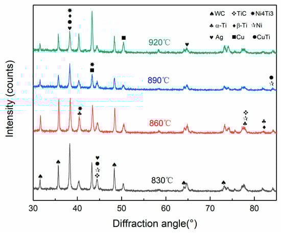
Figure 8.
Surface XRD of the composite coating.
3.4. Composite Coating Cross-Section Microhardness Test
The hardness results are shown in Figure 9. At the same brazing temperature, the hardness from the substrate to the coating gradually increased, and the hardness of the coating was nearly twice that of the copper substrate. As the brazing temperature increased, the hardness of the substrate was basically unchanged, and the hardness of the brazing seam and the coating increased. Until the brazing temperature reached 860 °C, the hardness reached the highest. The temperature rose continuously and the hardness dropped sharply.
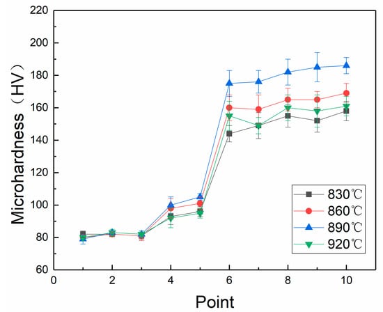
Figure 9.
Linear hardness distributions.
3.5. Bonding Strength between the Coating and Substrate
The shear strength test results are shown in Figure 10. Under the conditions of brazing temperatures of 830 °C, 860 °C, 890 °C, and 920 °C, the bonding strength between the coating and the substrate was 184.4 MPa, 201.5 MPa, 227.9 MPa, and 176.3 MPa, respectively. It could be seen that the bonding strength between the coating and the substrate increased with the increase of the brazing temperature, and the bonding strength reached the highest at the brazing temperature of 890 °C. Since the harmful Ti–Cu compound was present in the composite coating when the brazing temperature reached 920 °C, the bonding strength was suddenly reduced. Therefore, the excessive brazing temperature was advantageous for the reaction to proceed sufficiently but had a great influence on the bonding strength of the coating.
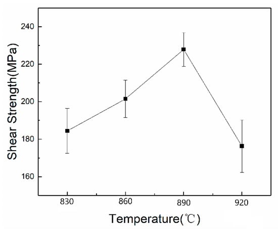
Figure 10.
Shear strength of coatings at different temperatures.
4. Conclusions
- (1)
- Using Ag-Cu-Ti solder, the WC mass fraction was 40%, the heat preservation was 30 min, the vacuum was better than 10−3 Pa and the brazing temperature on the copper surface were 830 °C, 860 °C, 890 °C, and 920 °C. All four coatings were well bonded.
- (2)
- As the brazing temperature increased, the Ni wrapped around the WC, was continuously consumed, and more and more Cu was on both sides of the brazing seam. If the temperature was too high, the bonding of the coating to the substrate was not favorable. The interface between the four coatings and the substrate was scanned. The elements W and Ti hardly diffused into the brazing seam and the substrate. The elements Ag and Cu diffused into the substrate, and the interface between the brazing seam and the substrate was metallurgically bonded.
- (3)
- The Vicker’s hardness test results and bond strength results of the composite coatings showed that the brazing seam and the coating had the highest hardness, the highest bonding strength and the best mechanical properties when the brazing temperature was 890 °C.
Author Contributions
All of the named authors were involved in the work leading to the publication of this paper and have read the paper before this submission. Conceptualization—X.X.; Methodology—X.X. and Y.W.; Validation—C.L., Y.W., J.Z. and C.X.; Formal Analysis—X.X. and Y.W.; Investigation—X.X., C.L. and C.X.; Resources—J.Z.; Data Curation—X.X.; Writing-Original Draft Preparation—X.X. and C.L.; Writing-Review & Editing—J.Z. and C.X.; Supervision—J.Z. and C.X.; Project Administration—J.Z., X.X. and C.X.; Data curation—X.X.; Resources, X.X. and J.Z.; Visualization—J.Z. and C.X.
Funding
This project was supported by Postgraduate Research & Practice Innovation Program of Jiangsu Province (Grant No. KYCX19_1672).
Conflicts of Interest
The authors declare no conflict of interest.
References
- Peters, D.T. Copper alloys for industrial hardware. Adv. Mater. Process. 1996, 150, 30–32. [Google Scholar]
- Xu, X.; Ding, H.; Xia, C.; Zou, J.; Wang, Y. Effect of Brazing Temperature on the Microstructure and Chosen Properties of WC–10Ni/NiCrBSi Composite Coatings Produced by Vacuum Cladding from Flexible Coated Cloths. Coatings 2019, 9, 214. [Google Scholar] [CrossRef]
- Verezub, O.; Kálazi, Z.; Buza, G.; Verezub, N.V.; Kaptay, G. Classification of laser beam induced surface engineering technologies and synthesis of steel substrate surface nanocomposites. Surf. Eng. 2013, 27, 428–435. [Google Scholar] [CrossRef]
- Deng, Z.H.; Pan, Z.; Wu, Q.P.; Zhang, G.F.; Zhang, B. Research on Finite Element Simulation and Experiment of Temperature Field for Surface Cutting of Nanostructured WC/12Co Coatings. Key Eng. Mater. 2012, 522, 167–172. [Google Scholar] [CrossRef]
- Gao, J.C.; Zhang, Y.P.; Sheng, S.X.; Xie, L.H.; Wang, X.J. Study on Spraying Ceramic Substrate Composite Heat Resistant Coating on Copper Surface. Ordnance Mater. Sci. Eng. 1992, 15, 53–57. (In Chinese) [Google Scholar]
- Gao, F.; Wang, T.; Shen, Q.; Zou, J.S. Study on the Process of Electrosparking Ni/Metal Ceramic Coating on Copper. J. Jiangsu Univ. Sci. Technol. 2011, 25, 219–223. [Google Scholar]
- Tian, F.J.; Liu, W.J.; Shang, X.F. Experimental Study on Laser Cladding Ni60A Coating on Pure Copper Substrate. Metal Heat Treat. 2008, 33, 35–37. [Google Scholar]
- Xu, X.P.; He, L.; Xia, C.; Zou, J.S. Microstructure and Interface Bonding Strength of WC-10Ni/NiCrBSi Composite Coating by Vacuum Brazing. High Temp. Mater. Process. 2019, 38, 60–68. [Google Scholar] [CrossRef]
- Huang, L.X.; Cao, Y.P.; Lin, C.; Zhou, M.S.; Zhao, X.J. Study on Vacuum Cladding Ni-Based Alloy-Tungsten Carbide Composite Coating. Surf. Technol. 2009, 38, 25–27. [Google Scholar]
- Xu, X.P.; Ma, Q.J.; Xia, C.Z. Micromorphology change and microstructure of Cu-P based amorphous filler during heating process. High Temp. Mater. Process. 2019, 38, 1–11. [Google Scholar] [CrossRef]
- Xu, X.; Wang, Y.; Zou, J.; Xia, C. Interfacial Microstructure and Properties of Si3N4 Ceramics/Cu/304 Stainless Steel Brazed by Ti40Zr25B0.2Cu Amorphous Solder. Materials 2018, 11, 2226. [Google Scholar] [CrossRef] [PubMed]
© 2019 by the authors. Licensee MDPI, Basel, Switzerland. This article is an open access article distributed under the terms and conditions of the Creative Commons Attribution (CC BY) license (http://creativecommons.org/licenses/by/4.0/).