Article

Effect of Heat Treatment on the Cavitation Erosion Performance of WC–12Co Coatings

1
College of Mechanical Engineering, Yangzhou University, Yangzhou 225127, China
2
College of Hydraulic Science and Engineering, Yangzhou University, Yangzhou 225100, China
3
Department of Mechanical Engineering, Yangzhou Polytechnic College, Yangzhou 225009, China
*
Authors to whom correspondence should be addressed.
Coatings 2019, 9(10), 690; https://doi.org/10.3390/coatings9100690
Submission received: 26 September 2019 / Revised: 21 October 2019 / Accepted: 21 October 2019 / Published: 22 October 2019

Abstract

:
WC–12Co coatings were deposited on 16Cr5Ni stainless steel substrate by high-velocity oxygen fuel (HVOF) process, followed by a one-hour heat-treatment in a tube furnace with a nitrogen atmosphere at 650, 800, 950, and 1100 °C, respectively. The influence of heat-treatment temperature on properties and cavitation erosion resistance of as-sprayed and heat-treated WC–12Co coatings was studied. The cavitation erosion test was carried out with ultrasonic cavitation erosion equipment. The porosity, microhardness, phase composition, as well as surface and cross-section morphology of the coatings were characterized. The coating heat-treated at 800 °C showed three typical cavitation erosion stages and exhibited the best cavitation erosion resistance. The cavitation erosion resistance was closely related to the coating microstructure and heat-treatment process. 3D optical microscopy was used to analyze the eroded surface of the coatings. The cavitation erosion mechanism of the coatings was discussed.

1. Introduction

Cavitation erosion (CE) is a recurrent phenomenon of bubble nucleation, growth, and collapse caused by the change of pressure, velocity, or temperature of the liquid [1,2,3]. The collapse of bubbles is accompanied by high-pressure micro-jets and stress waves causing the material surface damage of flow components of hydraulic machinery, such as blades, guide vanes, needles, sealing rings, etc., which seriously affects the operation efficiency and service life of the equipment [4,5].
In recent years, with the development of surface technology, there are more and more reports on surface modification and strengthening of materials [6,7]. At present, coatings prepared by high velocity oxy-fuel (HVOF) or atmospheric plasma spraying (APS) methods are customarily used to realize the surface strengthening of hydraulic mechanical materials. HVOF has been favored by researchers due to the high particle velocity and low flame temperature which can obtain excellent properties of the coating with low porosity and high adhesion [8,9,10,11]. WC–Co cermet coatings have been widely used in industrial fields owing to its high hardness and toughness, excellent wear resistance as well as good stability [12,13,14]. Gao et al. [15] found that the friction coefficient and wear resistance were enhanced coinstantaneous by HVOF-sprayed WC-(nano WC–Co) coatings. Ding et al. [16] observed that HVOF prepared nanostructured WC–12Co coating exhibits the excellent cavitation erosion resistance due to the dense microstructure, low porosity as well as high fracture toughness of the coating. According to Hong’s study [17], porosity played a dominant role in cavitation erosion resistance of near-nanostructured WC–10Co–4Cr coatings deposited by HVOF. In addition, post-treatment methods optimized the microstructure of the coating for better performance. Heat-treatment is a common way to change the inherent layered structure, phase composition, and mechanical properties of the coating [18,19]. Stewart et al. [20] concluded that wear resistance of WC–17Co coating was obviously improved by heat-treatment. Lima’s investigation [21] indicated that the heat-treated 50%(WC–12Co) + 50%(NiCr) coating presented better cavitation erosion resistance compared with as-sprayed coating. It can be seen that heat treatment can improve the wear and cavitation erosion resistance of WC–Co coatings.
In the present study, WC–12Co coatings were deposited on 16Cr5Ni stainless steel substrates by HVOF process. Afterwards, the as-sprayed coatings were heat-treated at 650, 800, 950, and 1100 °C, respectively. Cavitation erosion experiments of as-sprayed and heat-treated coatings were carried out by an ultrasonic cavitation erosion apparatus. 3D optical profile was used to quantitatively characterize the cavitation erosion performance of the coatings.

2. Experimental

2.1. Materials

Commercial WC–12Co powder (Precursor Plasma Powders Co., Ltd., Yiyang, China) with a nominal size distribution of −45 to +15 μm was used as feedstock for HVOF spray. The chemical composition (in wt.) of the powder was: 11%–13% Co, and 5%–5.6% C and W as the balance. The spherical morphology of the powder is clearly shown in Figure 1a, indicating a better fluidity during the powder feeding process. From Figure 1b, it can be observed that the powder surface has porous features, which improves the melting efficiency of the powder.

2.2. Coating Preparation

WC–12Co coatings were prepared on 16Cr5Ni stainless steel substrate by a kerosene-oxygen HVOF system (HV-80, Lijia, Zhengzhou, China). The 16Cr5Ni steel had a nominal chemical composition (in wt.): 0.03% C, 0.35% Si, 0.65% Mn, 15%–17% Cr, 5.5%–7% Ni, 0.03% P, 0.01% S, 0.5%–1% Mo and Fe as the balance. The initial size of the substrate was 80 mm × 50 mm. The sprayed samples were then machined into round specimens with a diameter of 16 mm. The parameters of HVOF process are shown in Table 1. Prior to coating deposition, the substrate was dried after being cleaned with acetone, and then sand blasted by Al2O3 (600–650 μm) to increase the surface roughness and improve adhesion of the coating on substrate.

2.3. Heat-Treatment

The WC–12Co coatings were heat-treated at 650, 800, 950, and 1100 °C, respectively, in a tube furnace with nitrogen atmosphere. A constant heating rate of 5 °C·min−1 was used and maintained at peak temperature for 1 h, followed by natural-cooling to room temperature. In this paper, the WC–12Co coatings heat-treated at 650, 800, 950, and 1100 °C, are abbreviated to heat-treated (HT) 650, HT 800, HT 950, and HT 1100, respectively.

2.4. Coating Characterization

The phase compositions of the powder, as-sprayed and heat-treated coating were identified by using X-ray diffraction (XRD, D8 Advance, Bruker, Bremen, Germany) with Cu Kα radiation (λ = 1.5405 Å) at 40 kV, 40 mA. Scanning electron microscopy (FE-SEM, S4800Ⅱ, Hitachi, Tokyo, Japan) was employed to characterize coating microstructure before and after cavitation erosion tests. The microhardness of as-sprayed and heat-treated coatings was examined by a micro-Vickers hardness tester (HV-1000A, Wuxi Huayin Testing Instrument Sales Co., Ltd., Huayin, China) at a load of 1 N with a dwell time of 15 s. The mean value was obtained by 15 measurements. The porosity of the coatings was analyzed through the ImageJ software (version 1.46). The surface roughness and the 3D profile of the coatings were measured with a three-dimensional optical microscope (Contour GT-K, Bruker, Billerica, MA, USA).

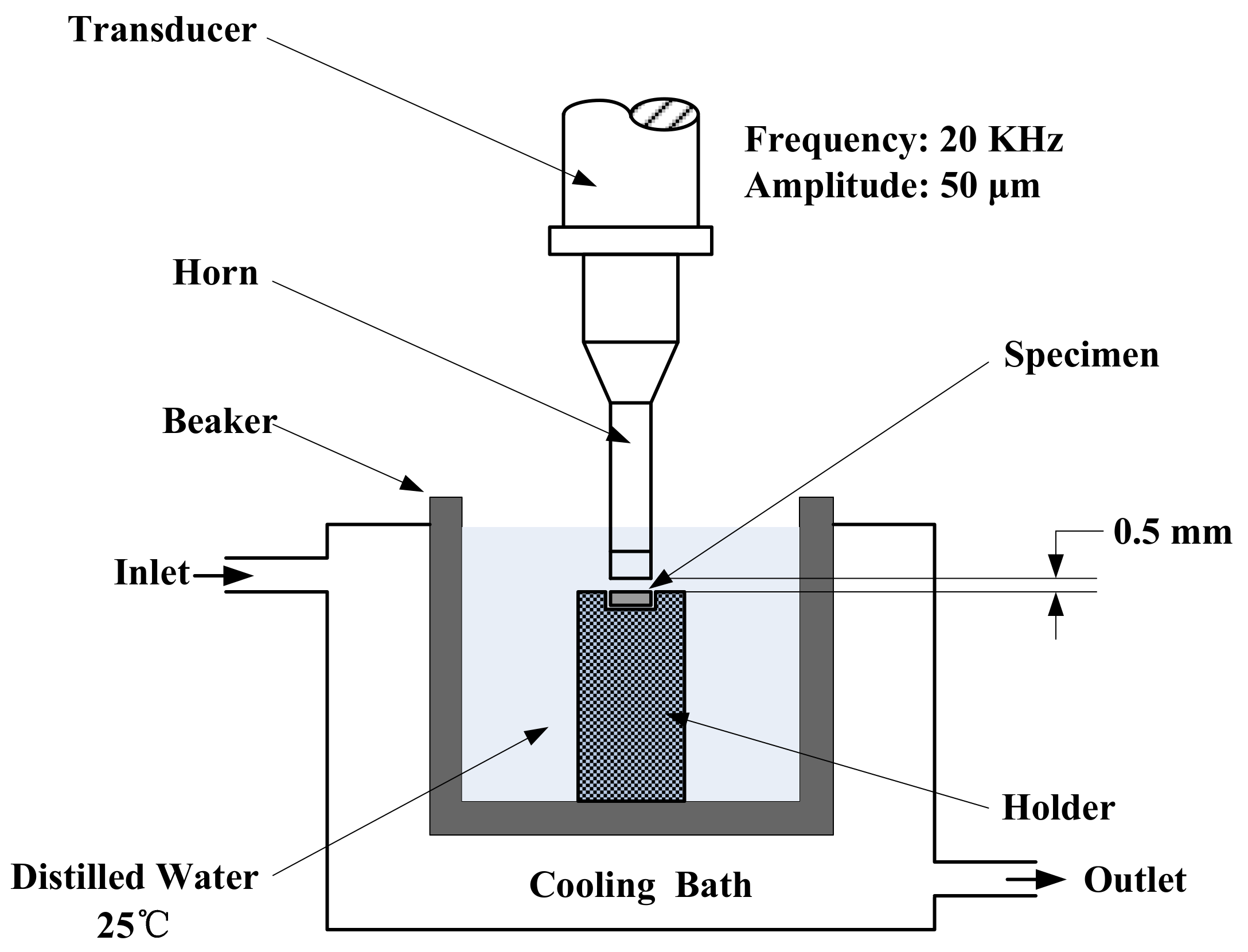
2.5. Cavitation Erosion Test

Cavitation erosion tests were carried out in distilled water at a temperature of 25 ± 2 °C by means of an ultrasonic cavitation erosion apparatus (KJ-1000K, FYCG-Ultrasonic Co., Ltd., Chaosheng, China) according to ASTM G32 standard [22]. The tests were performed with a vibration frequency of 20 kHz and an amplitude of 50 μm. The distance between the tip and the coating surface was 0.5 mm. The schematic diagram of cavitation erosion system is shown in Figure 2. Before the cavitation erosion test, the coatings were polished to a surface roughness of about 0.2 μm using 800, 1200, and 2000 mesh diamond grinding plates, respectively. During the cavitation test, the samples were cleaned with acetone every half hour, and then weighed with an analytical balance with a precision of 0.1 mg to calculate the mass loss of the coatings. The duration of cavitation erosion was 6 h.

3. Results and Discussions

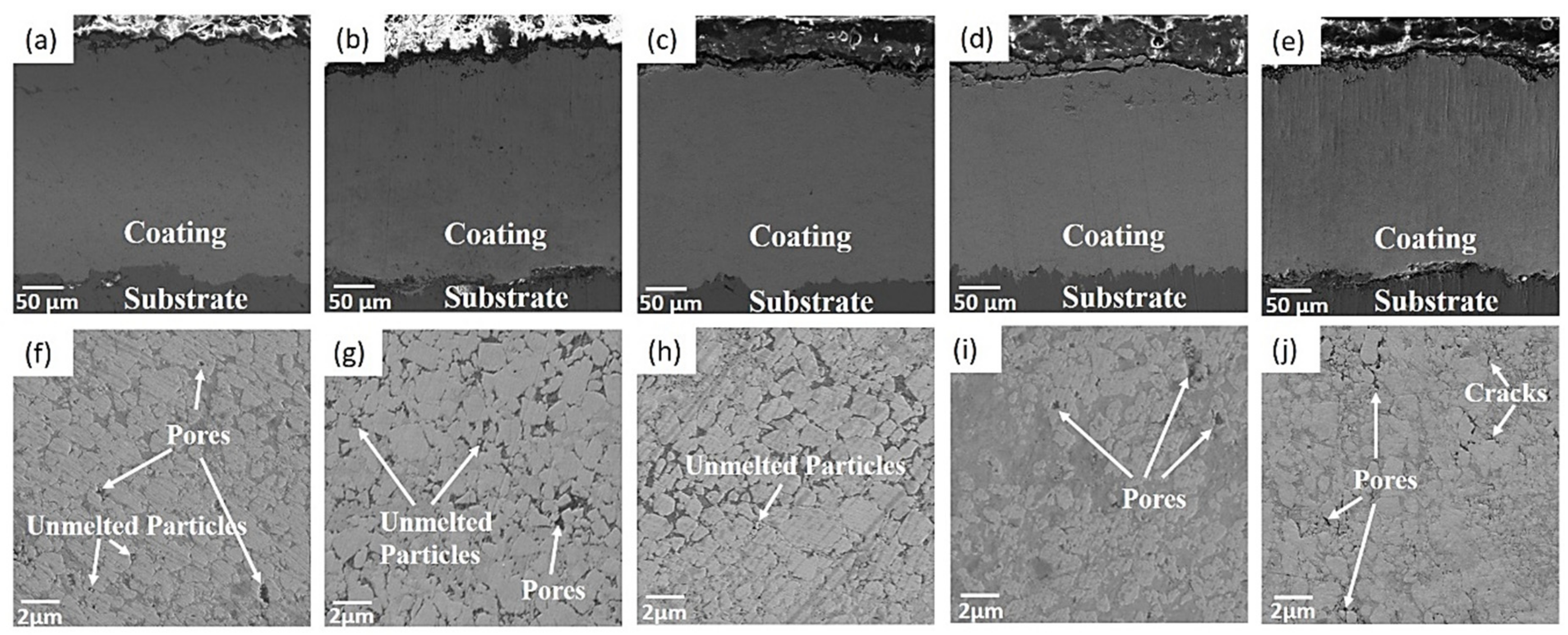
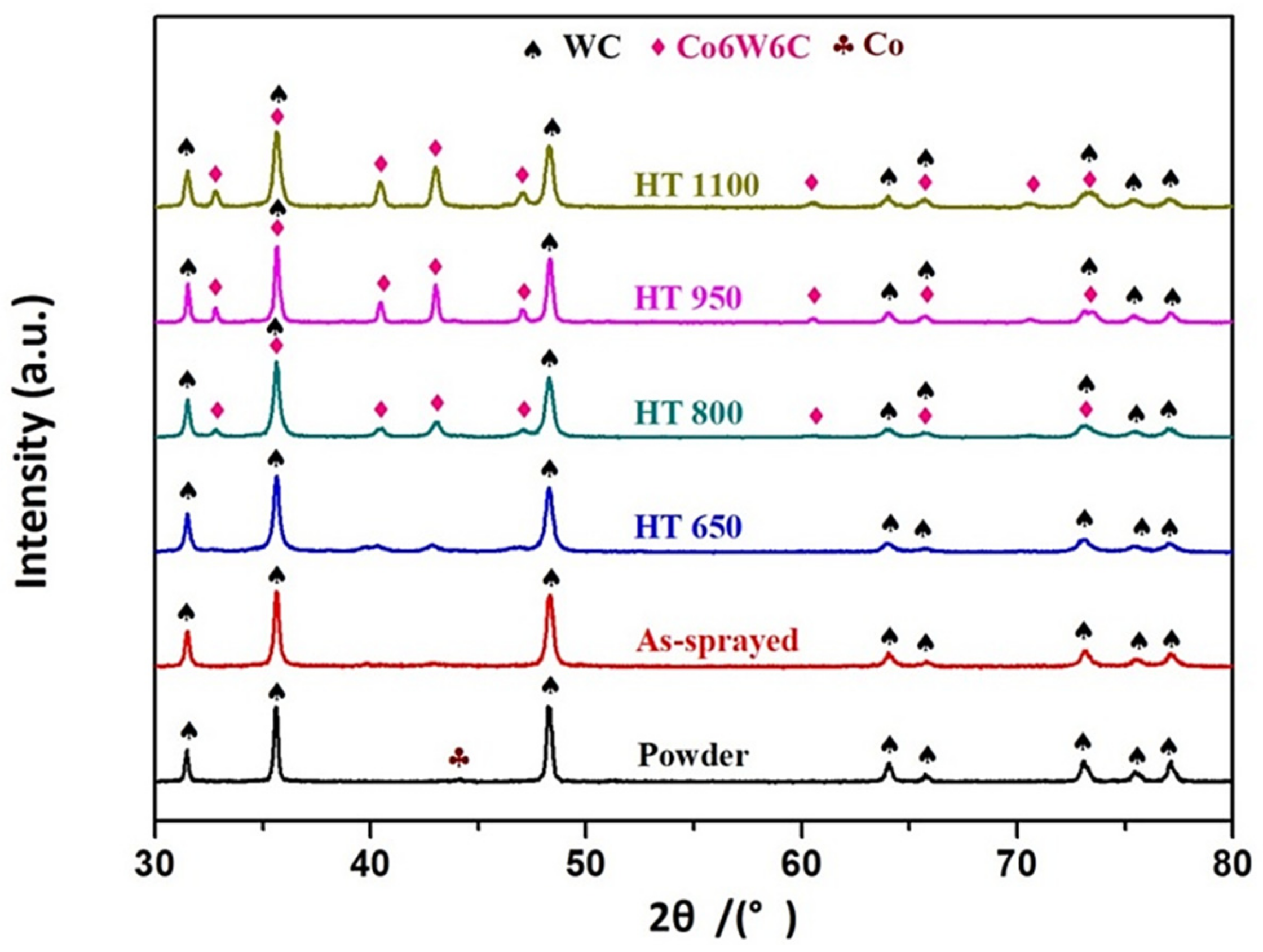
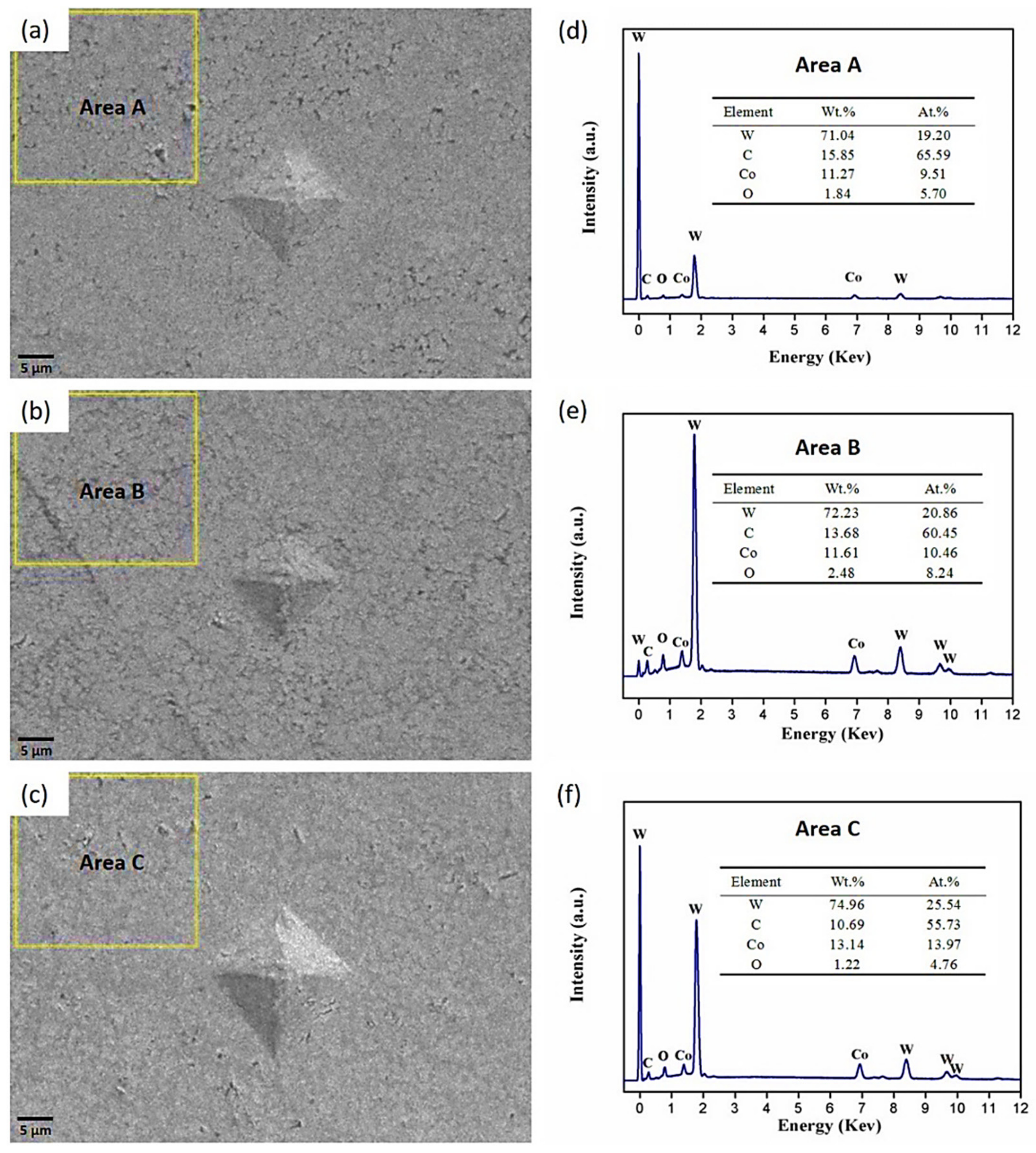
3.1. Microstructure and Phase Composition of the Coatings

Figure 3a–e illustrate that as-sprayed and heat-treated coatings are dense. The thickness of as-sprayed and heat-treated coatings are about 250 μm. Micro-defects, such as pores, unmelted WC particles as well as microcracks can be observed at high magnification as shown in Figure 3f–j.
Figure 4 illustrates the X-ray diffraction patterns of the coatings before and after heat-treatment. WC as the initial hard phase exists in feedstock power and coatings. In addition, the Co phase was identified at 44.2°. With the increase of heat-treatment temperature, the Co6W6C phase (η phase) appeared. At 650 °C, the peak intensity of Co6W6C phase is quite weak. From 800 to 1100 °C, the peak intensity of η phase increases with the heat-treatment temperature. On the contrary, the peak intensity of WC is attenuated. The result indicates that the WC phase is decarburized and dissolved in cobalt phase to form eta carbides Co6W6C [23,24].

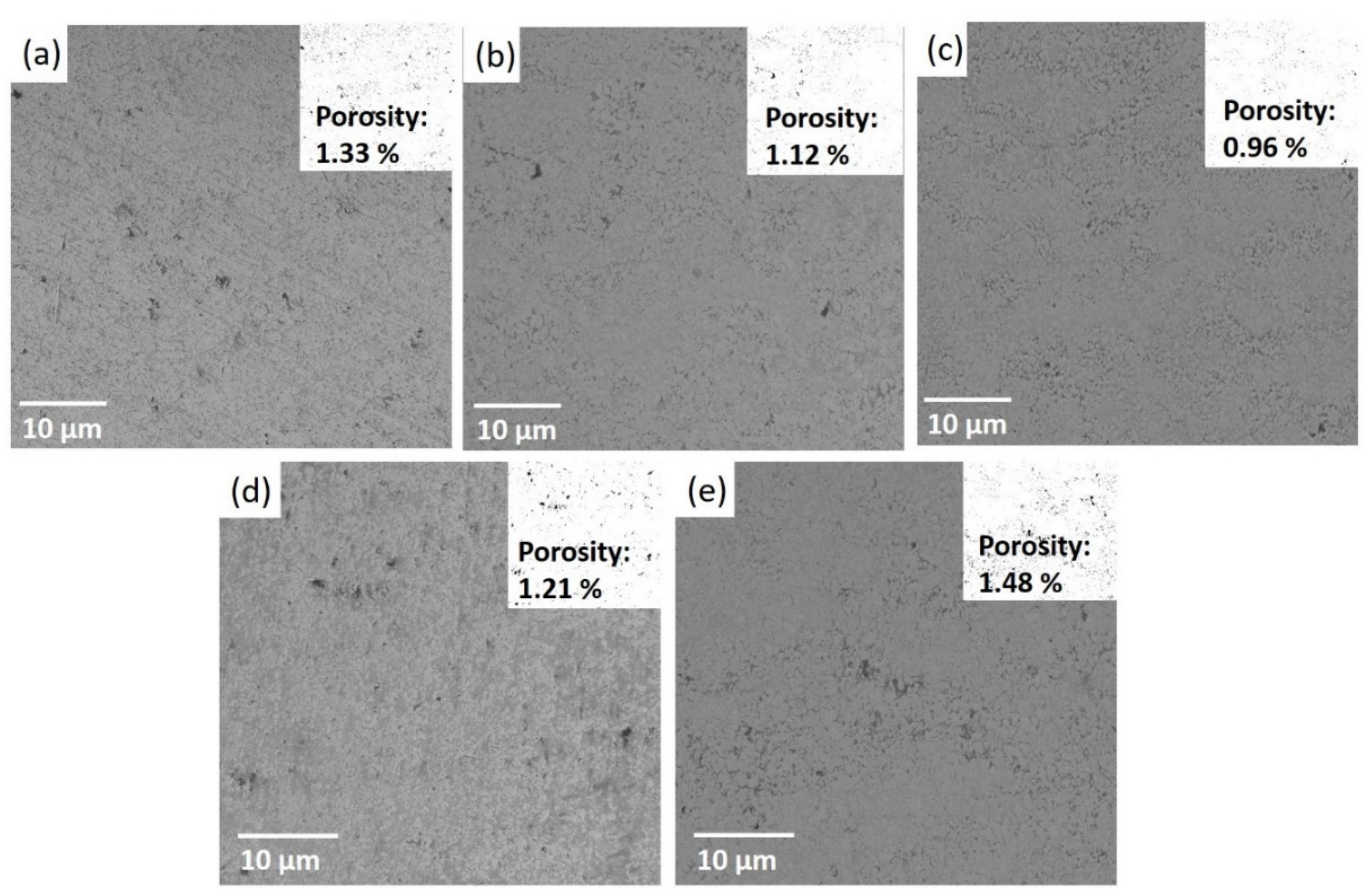
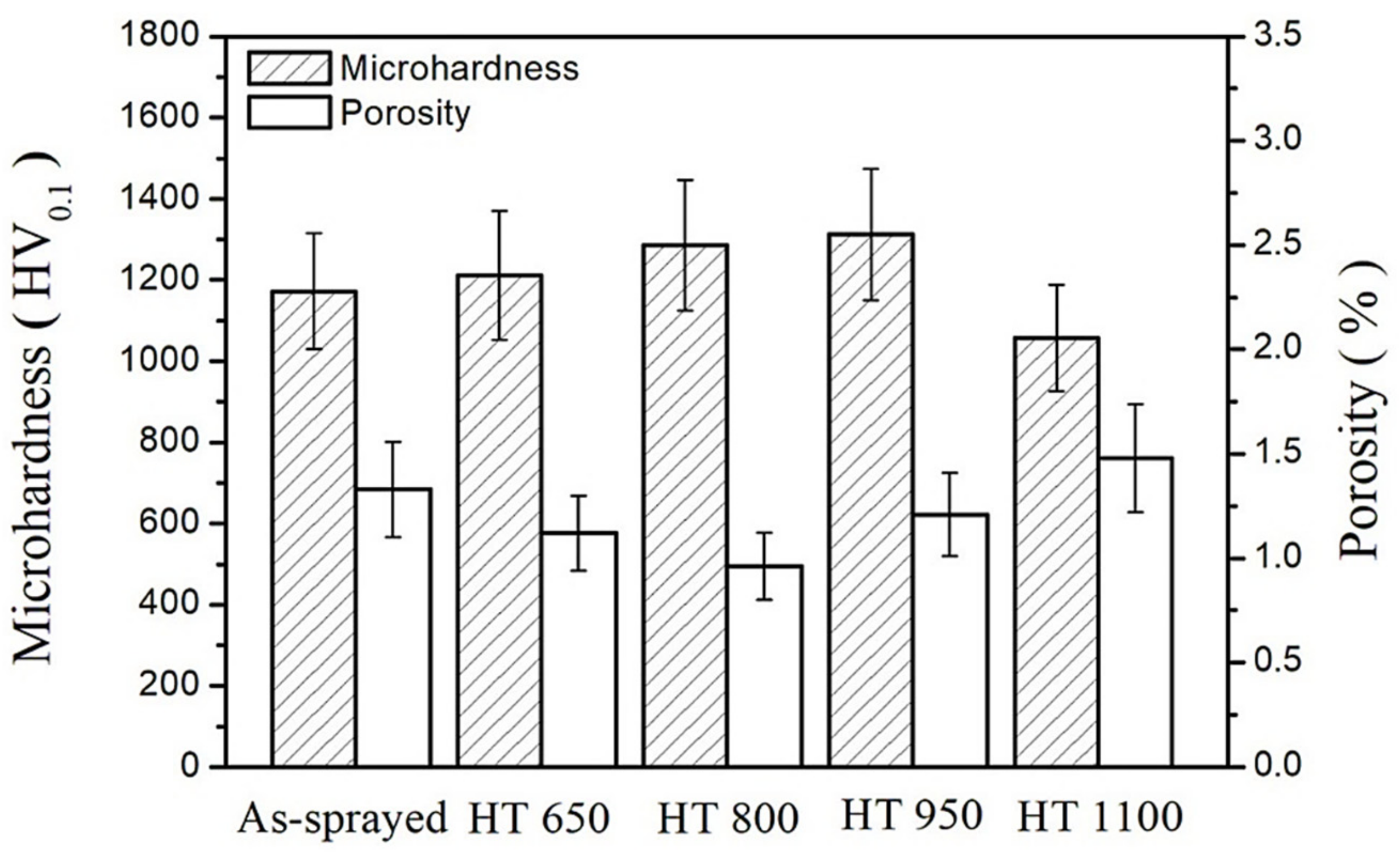
3.2. Porosity and Microhardness

The porosity of as-sprayed, HT 650, HT 800, HT 950, as well as HT 1100 coatings are 1.33%, 1.12%, 0.96%, 1.21%, and 1.48%, respectively, as shown in Figure 5. It is noticed that with the increase of heat-treatment temperature, the porosity of the coating decreases at first and then increases, and 800 °C is the optimized temperature. Compared with as-sprayed, HT 650, HT 950, and HT 1100 coatings, the HT 800 coating exhibits the most compact microstructure via “re-melting” (Figure 3c). It is obvious that the “re-melting” effect of HT 650 is inferior to that of the HT 800 coating. However, when the heat-treatment temperature is further increased to 950 and 1100 °C, more WC was transformed into η phase Co6W6C. Co6W6C has a higher molar volume than WC [25], which led to the production of micro-pores and cracks surrounding η phase. In addition, during the process of high-temperature heat-treatment, the “Kirkendall” pores [26,27] are produced by the diffusion of elements between the boundary of the coating and substrate leading to the highest porosity for HT 1100 coating.
The microhardness of as-sprayed, HT 650, HT 800, HT 950, and HT 1100 coatings are 1172, 1211, 1286, 1312, and 1057 HV, respectively, as shown in Figure 6 (the standard deviation is adopted as the error bar).
It is noticed that microhardness is closely related to porosity and phase composition of the coatings. The variation on microhardness can be divided into two stages: the first is corresponding to the range of 0–800 °C, the porosity is the dominant factor to determine microhardness due to the low level of phase transformation. The second period is in the range of 950–1100 °C. HT 950 coating shows the highest microhardness due to the aggravation of phase transition (a large number of hard phase Co6W6C has been formed) in this stage, although the porosity of HT950 coating is higher than that of the HT 800 coating. High porosity at 1100 °C offsets the positive effect of hard phase on coating hardness. Consequently, HT 1100 coating presents the lowest microhardness.
Figure 7 presents the indentation and energy-dispersive spectroscopy (EDS, S4800Ⅱ, Hitachi, Tokyo, Japan) analysis of as-sprayed, HT 800 and HT 1100 coating. The indentation sizes of the three coatings are consistent with the corresponding microhardness values. The EDS results show that the relative contents of C, W, and Co elements in the three coatings have changed, which confirm the phase transition.

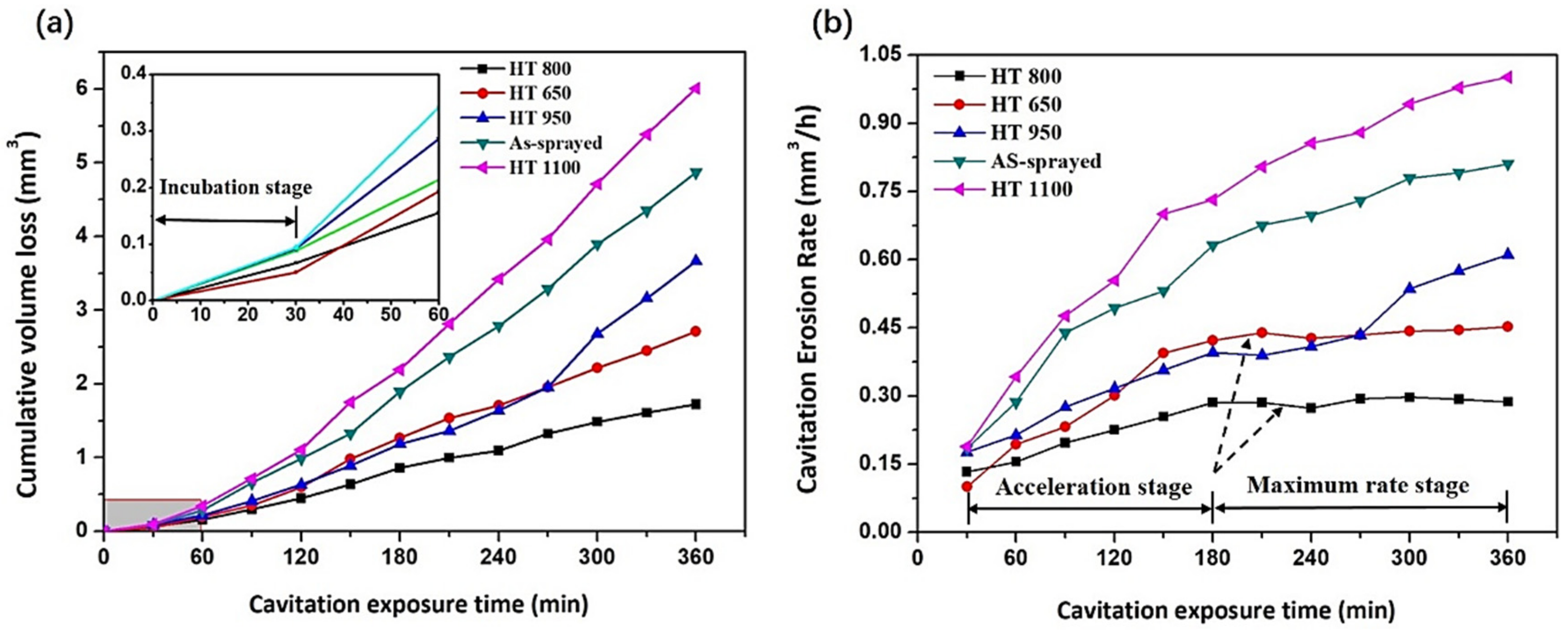
3.3. Volume Loss and Cavitation Erosion Rate

Figure 8 shows the volume loss and corresponding cavitation erosion rate curves for all the coatings as a function of cavitation time. The cavitation erosion rate is defined as the volume loss of the coating per unit time. Generally, three typical stages would experience in cavitation erosion process of material [28,29,30]: (1) the incubation stage, the cavitation erosion rate can be ignored in the initial time; (2) the acceleration stage, the cavitation erosion rate is increased at this stage; (3) and the maximum rate (steady) stage, the cavitation erosion rate is a constant during this period. As shown in Figure 8a, the volume loss of all the coatings increases with the increase of time. After the cavitation erosion test for 6 h, the volume loss of as-sprayed, HT 650, HT 800, HT 950, and HT 1100 coatings were 4.87, 2.71, 1.72, 3.67, and 6.01 mm3, respectively, which means that HT 800 coating exhibited best cavitation erosion resistance. On the contrary, the HT 1100 coating showed the worst cavitation erosion resistance. The partial enlarged detail of Figure 8a illustrates that the cavitation erosion rate of all the five coatings in the initial 30 min is tiny (the slope of this interval is very small). The value of the volume loss for the five coatings at the initial 30 min does not exceed 0.1 mm3 (the volume loss of this stage to the total volume loss ratio is less than 5%), therefore, this period is considered as the incubation stage of all the coatings. It is noticed that only the HT 650 and HT 800 coatings presented the three typical stages among the five coatings as shown in Figure 8b. In the period of 30–180 min, it can be clearly distinguished that the cavitation erosion rates of HT 650 and HT 800 coatings were in an increasing stage, and this interval can be identified as the cavitation erosion acceleration period. During the stage of 180–360 min, the cavitation erosion rates of the HT 650 and HT 800 coatings tended to be stable (the average value of cavitation erosion rate of the HT 650 and HT 800 coatings were 0.437 and 0.288 mm3·h−1, respectively, in this stage), which should be in the third stage, namely, the maximum rate stage (steady stage). On the other hand, it was observed that the cavitation erosion rate of as-sprayed, HT 950 and HT 1100 coatings kept growing after 30 min, especially significant for the HT 1100 coating. Consequently, no maximum rate stage was identified for as-sprayed HT 950 and HT 1100 coatings. The different performance of the five coatings may be caused by the following two factors. Firstly, the micro defects of the coatings such as pores, cracks, unmelted, or semi-melted particles play a negative role in cavitation erosion process [31,32,33,34]. It is clearly observed from Figure 9 that microcracks, pores, and unmelted that particles existed in the surface of the HT 1100 coating before cavitation erosion. Initial pores and cracks usually supply the places for bubble nucleation. Secondly, the phase transition is also a crucial factor which affects the cavitation erosion performance of the coating. Due to the phase transition, the cavitation erosion resistance of the HT 1100 coating is weakened by the occurrence of pores together with the consumption of the bonding phase Co.

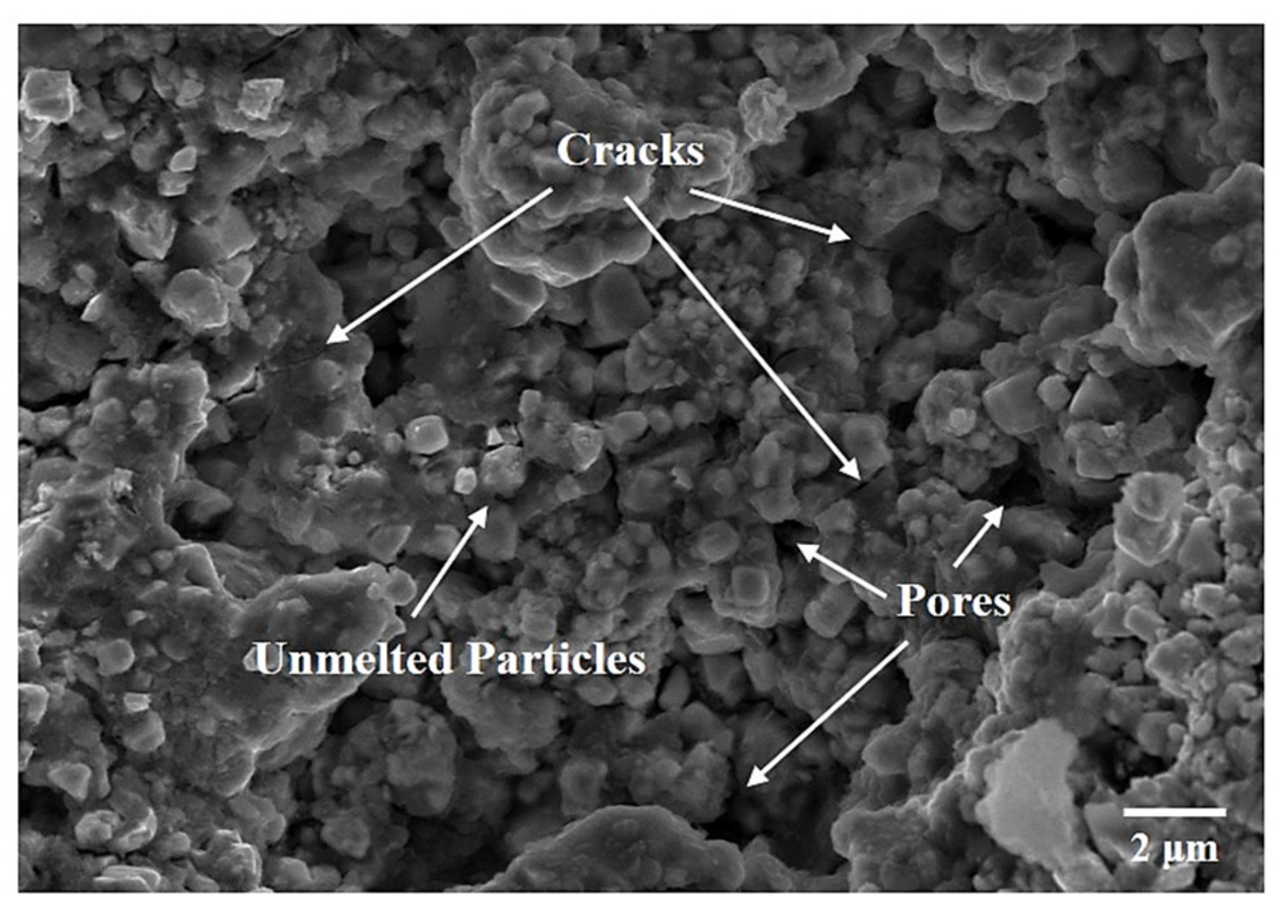
3.4. Cavitation Erosion Mechanism

Surface roughness is an important parameter to quantitatively characterize the irregular degree on micron-nanometer scale, which can be used to evaluate the cavitation erosion level of coating surface [35,36]. Figure 10 illustrates the 3D morphology of the HT 800 coating surface before and after 2, 4, and 6 h cavitation erosion tests. It can be observed that, with the accumulation of cavitation erosion time, the surface roughness Ra increases continuously. Meanwhile, the number of cavitation pits and the area of the cavitation erosion regions rise gradually, reflecting the gradual deterioration of the surface. The other parameter Rv of the surface roughness is characterized by the distance between the valley bottom line and the average line of the contour profile, which reflects the extreme value of the cavitation erosion in the local area. With reference to Figure 10, the depth of the lowest depression of the coating surface was about 4 μm before cavitation erosion whereas the depth was about 83 μm after 6 h’ exposure.
After 6 h cavitation erosion test, the SEM and 3D images of eroded surfaces of all the coatings are presented in Figure 11. It can be seen that the surface of all the coatings suffered cavitation erosion damage. The cavitation craters, spalling of coating, as well as cracks connected by micro-pores can be clearly observed from Figure 11a–e. Figure 11a exhibits the layer-like eroded characteristic of as-sprayed coating, which was produced by peeling of splats. The eroded surface is divided into step-shaped regions marked 1, 2, and 3. Region 1 is the undestroyed surface, and regions 2 and 3 demonstrate two-step surfaces. It is noticed that region 3 was in the lowest position, which means the region suffered the most serious cavitation erosion. Figure 11e illustrates the eroded surface of the HT 1100 coating after the whole test. Except for the five areas (ⅰ, ⅱ, ⅲ, ⅳ, ⅴ) marked by dotted lines, the coatings in other places have been peeled off. In addition, the surface roughness values of as-sprayed HT 650, HT 800, HT 950, and HT 1100 coatings after 6 h cavitation erosion were 15.343, 10.545, 8.695, 12.952 and 21.573 μm, respectively, as shown in Figure 11f–j.
It was determined that the value of the surface roughness of the coating is positively correlated with the corresponding average cavitation erosion rate as presented in Figure 12. In other words, the surface roughness value can also be used to quantitatively evaluate the cavitation erosion behavior of the materials.
The initial micro-defects, such as pores, microcracks, unmelted particles of the coating will become weak points in the cavitation erosion test. During cavitation erosion test, the bubbles produced by ultrasonic vibration horn will firstly collapse above the surface of the coating to form a high-pressure water jet with a stress wave. Then the tiny bubbles formed again during the process will attach to the pores or cracks, which will nucleate, grow, collapse, and form micro-jets and shock waves to further damage the pores or cracks. The cracks parallel to the coating surface are gradually extended to the adjacent cracks or pores under the repeated impact of the shock waves and the micro-jets, resulting in peeling off debris, unmelted particles, and the hard phase from the coating. The cracks perpendicular to the surface propagate to the depth under repeated impact, which further accelerates the failure of the coating. The schematic of cavitation erosion mechanism of the coating is illustrated in Figure 13.

4. Conclusions

In this work, HVOF-sprayed WC–12Co coatings were heat-treated at 650, 800, 950, and 1100 °C. The erosion behaviors of the as-sprayed and heat-treated coatings were characterized, and the erosion mechanism was discussed. The main conclusions can be drawn as follows:
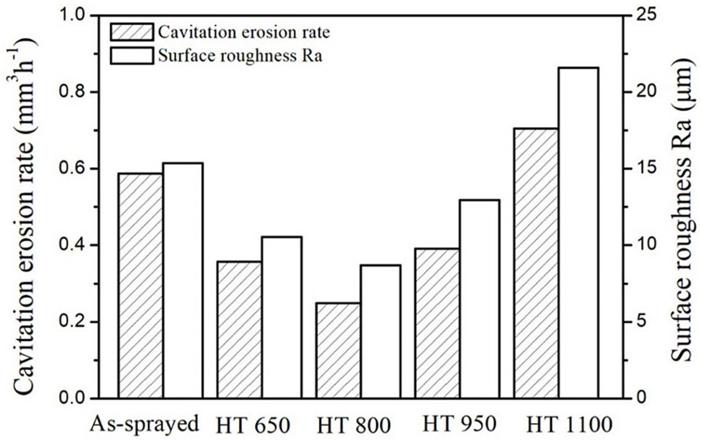
  • The volume loss of as-sprayed HT 650, HT 800, HT 950, and HT 1100 coating after 6 h of cavitation erosion tests was 4.87, 2.71, 1.72, 3.67, and 6.01 mm3, respectively, which means that the coating heat-treated at 800 °C exhibits the best cavitation erosion resistance.
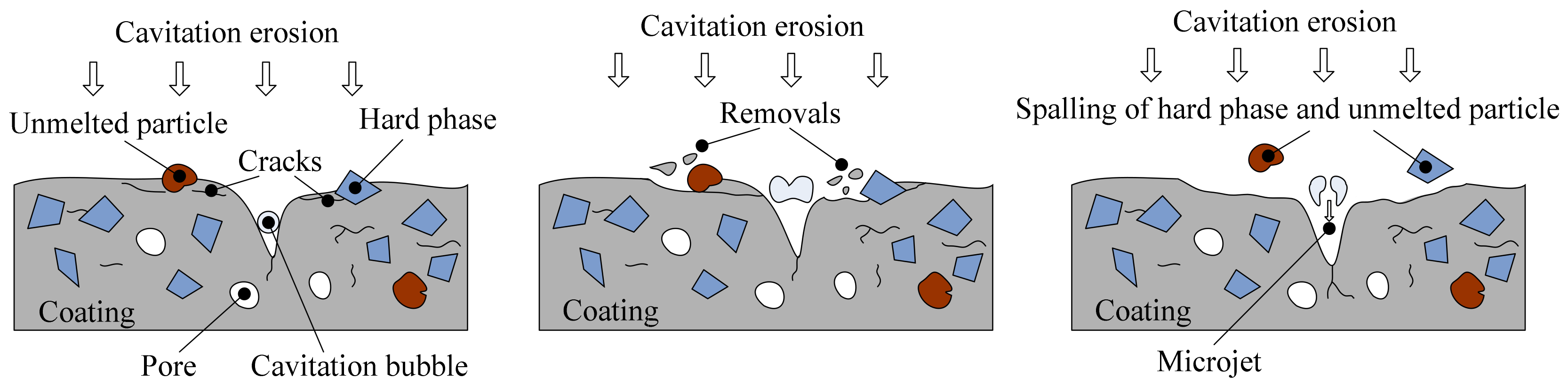
  • The cavitation rate of the coating is closely related to the micro defects of the coatings, such as pores, cracks, unmelted or semi-melted particles, and phase transitions that occurred during the heat treatment process.
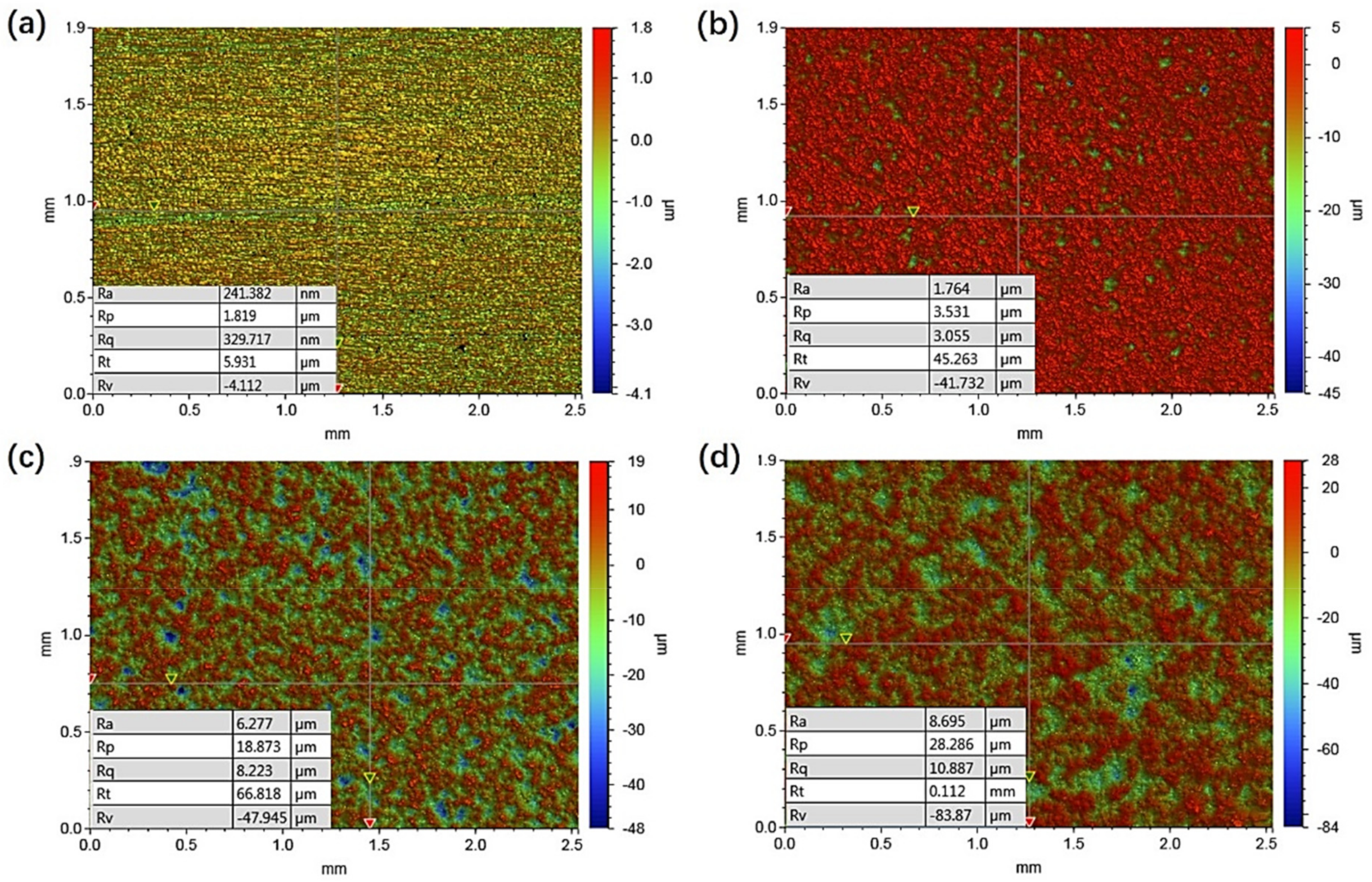
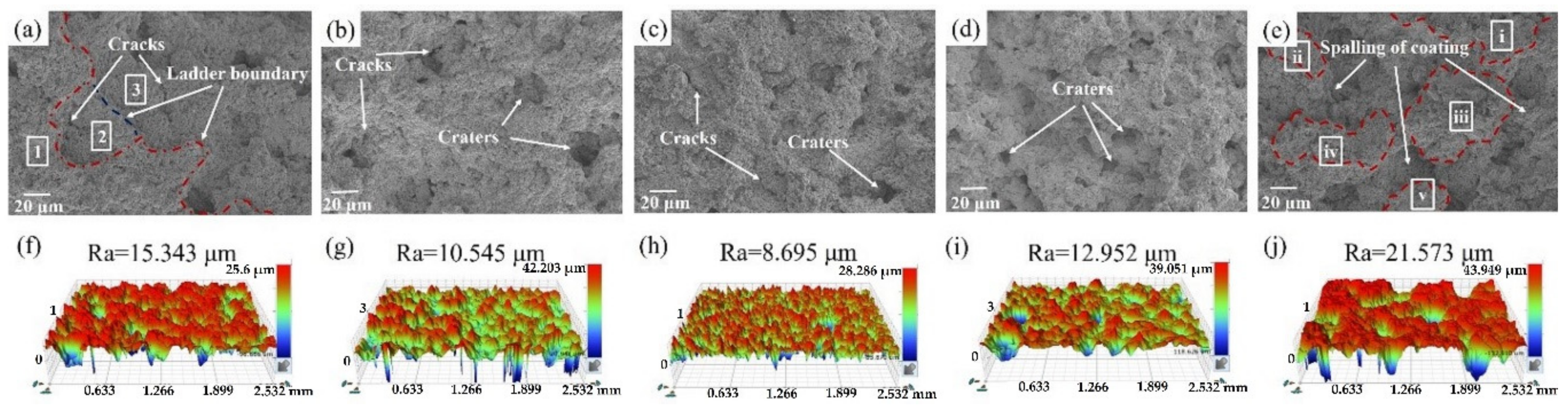
  • The surface roughness values, Ra, of as-sprayed HT 650, HT 800, HT 950, and HT 1100 coatings after 6 h cavitation erosion were 15.343, 10.545, 8.695, 12.952, and 21.573 μm, respectively. The surface roughness is positively correlated with the cavitation erosion rate, which indicates that the surface roughness can be used to quantitatively evaluate the cavitation erosion behavior of the materials.
  • The existence of debris, unmelted particles, and hard phases, as well as the propagation and connection of cracks and pores in the coatings are the dominant cavitation erosion mechanisms.

Author Contributions

Conceptualization: J.D. and J.Z.; methodology: J.D. and C.Z.; software: J.D.; investigations: J.D., J.Z. and C.Z.; writing—original draft preparation: J.D.; writing—review and editing: J.Z. and C.Z.; funding acquisition: C.Z. and J.D.

Funding

This research was funded by the Yangzhou Science Fund for Distinguished Young Scholars under grant no. YZ2017096; Marine Science and Technology Project of Jiangsu Province under grant no. HY2017-10; Yangzhou Polytechnic College Science Fund under grant no. 01432400314; and the Yangzhou City–Yangzhou University Cooperation Foundation under grant no. YZU201801.

Conflicts of Interest

The authors declare no conflict of interest.

References

  1. Caupin, F.; Herbert, E. Cavitation in water: A review. Comptes Rendus Physique 2006, 7, 1000–1017. [Google Scholar] [CrossRef]
  2. Dorji, U.; Ghomashchi, R. Hydro turbine failure mechanisms: An overview. Eng. Fail. Anal. 2014, 44, 136–147. [Google Scholar] [CrossRef]
  3. Gohil, P.P.; Saini, R.P. Coalesced effect of cavitation and silt erosion in hydro turbines—A review. Renew. Sustain. Energy Rev. 2014, 33, 280–289. [Google Scholar] [CrossRef]
  4. Okada, T.; Iwai, Y.; Awazu, K. A study of cavitation bubble collapse pressure sand erosion part 1: A method for measurement of collapse pressures. Wear 1989, 133, 219–232. [Google Scholar] [CrossRef]
  5. Chen, H.-S.; Liu, S.-H. Inelastic damages by stress wave on steel surface at the incubation stage of vibration cavitation erosion. Wear 2009, 266, 69–75. [Google Scholar] [CrossRef]
  6. Liu, J.; Bai, X.-Q.; Chen, T.-Z.; Yuan, C.-Q. Effects of cobalt content on the microstructure, mechanical properties and cavitation erosion resistance of HVOF sprayed coatings. Coatings 2019, 9, 534. [Google Scholar] [CrossRef]
  7. Shi, Z.-P.; Wang, J.-Q.; Wang, Z.-B.; Qiao, Y.-X.; Xiong, T.-Y.; Zheng, Y.-G. Cavitation erosion and jet impingement erosion behavior of the NiTi coating produced by air plasma spraying. Coatings 2018, 8, 346. [Google Scholar] [CrossRef]
  8. Vashishtha, N.; Khatirkar, R.K.; Sapate, S.G. Tribological behavior of HVOF sprayed WC–12Co, WC–10Co–4Cr and Cr3C2-25NiCr coatings. Tribol. Int. 2017, 105, 55–68. [Google Scholar] [CrossRef]
  9. Peat, T.; Galloway, A.; Toumpis, A.; Harvey, D.; Yang, W.-H. Performance evaluation of HVOF deposited cermet coatings under dry and slurry erosion. Surf. Coat. Technol. 2016, 300, 118–127. [Google Scholar] [CrossRef] [Green Version]
  10. García-Rodríguez, S.; Torres, B.; López, A.J.; Otero, E.; Rams, J. Characterization and mechanical properties of stainless steel coatings deposited by HVOF on ZE41 magnesium alloy. Surf. Coat. Technol. 2019, 359, 73–84. [Google Scholar] [CrossRef]
  11. Milanti, A.; Koivuluoto, H.; Vuoristo, P.; Bolelli, G.; Bozza, F.; Lusvarghi, L. Microstructural characteristics and tribological behavior of HVOF-sprayed novel Fe-based alloy coatings. Coatings 2014, 4, 98–120. [Google Scholar] [CrossRef]
  12. Tillmann, W.; Hagen, L.; Stangier, D.; Paulus, M.; Tolan, M.; Sakrowski, R.; Biermann, D.; Freiburg, D. Microstructural characteristics of high-feed milled HVOF sprayed WC–Co coatings. Surf. Coat. Technol. 2019, 374, 448–459. [Google Scholar] [CrossRef]
  13. Ahmed, R.; Ali, O.; Faisal, N.H.; Al-Anazi, N.M.; Al-Mutairi, S.; Toma, F.L.; Berger, L.M.; Potthoff, A.; Goosen, M.F.A. Sliding wear investigation of suspension sprayed WC–Co nanocomposite coatings. Wear 2015, 322, 133–150. [Google Scholar] [CrossRef]
  14. Zafar, S.; Sharma, A.K. Dry sliding wear performance of nanostructured WC–12Co deposited through microwave cladding. Tribol. Int. 2015, 91, 14–22. [Google Scholar] [CrossRef]
  15. Gao, P.-H.; Chen, B.-Y.; Wang, W.; Jia, H.; Li, J.-P.; Yang, Z.; Guo, Y.-C. Simultaneous increase of friction coefficient and wear resistance through HVOF sprayed WC-(nano WC–Co). Surf. Coat. Technol. 2019, 363, 379–389. [Google Scholar] [CrossRef]
  16. Ding, X.; Ke, D.; Yuan, C.-Q.; Ding, Z.-X.; Cheng, X.-D. Microstructure and cavitation erosion resistance of HVOF deposited WC–Co coatings with different sized WC. Coatings 2018, 8, 307. [Google Scholar] [CrossRef]
  17. Hong, S.; Wu, Y.-P.; Zhang, J.-F.; Zheng, Y.-G.; Qin, Y.-J.; Lin, J.-R. Ultrasonic cavitation erosion of high-velocity oxygen-fuel (HVOF) sprayed near-nanostructured WC–10Co–4Cr coating in NaCl solution. Ultrason. Sonochem. 2015, 26, 87–92. [Google Scholar] [CrossRef]
  18. Liu, X.-M.; He, D.-Y.; Zhou, Z.; Wang, G.-H.; Wang, Z.-J.; Guo, X.-Y. Effect of post-heat-treatment on the microstructure of micro-plasma sprayed hydroxyapatite coatings. Surf. Coat. Technol. 2019, 367, 225–230. [Google Scholar] [CrossRef]
  19. González, M.A.; Rodríguez, E.; Mojardín, E.; Jiménez, O.; Guillen, H.; Ibarra, J. Study of the erosive wear behaviour of cryogenically and tempered WC–CoCr coating deposited by HVOF. Wear 2017, 376, 595–607. [Google Scholar] [CrossRef]
  20. Stewart, D.A.; Shipway, P.H.; McCartney, D.G. Influence of heat treatment on the abrasive wear behavior of HVOF sprayed WC–Co coatings. Surf. Coat. Technol. 1998, 105, 13–24. [Google Scholar] [CrossRef]
  21. Lima, M.M.; Godoy, C.; Modenesi, P.J.; Avelar-Batista, J.C.; Davison, A.; Matthews, A. Coating fracture toughness determined by Vickers indentation: An important parameter in cavitation erosion resistance of WC–Co thermally sprayed coatings. Surf. Coat. Technol. 2004, 177, 489–496. [Google Scholar] [CrossRef]
  22. ASTM G32-16. Standard Test Method for Cavitation Erosion Using Vibratory Apparatus; ASTM International: West Conshohocken, PA, USA, 2016.
  23. Wang, Q.; Li, L.-X.; Yang, G.-B.; Zhao, X.-Q.; Ding, Z.-X. Influence of heat treatment on the microstructure and performance of high-velocity oxy-fuel sprayed WC–12Co coatings. Surf. Coat. Technol. 2012, 206, 4000–4010. [Google Scholar] [CrossRef]
  24. Ghadami, F.; Sohi, M.H.; Ghadami, S. Effect of bond coat and post-heat treatment on the adhesion of air plasma sprayed WC–Co coatings. Surf. Coat. Technol. 2015, 261, 289–294. [Google Scholar] [CrossRef]
  25. Vashishtha, N.; Sapate, S.G.; Bagde, P.; Rathod, A.B. Effect of heat treatment on friction and abrasive wear behaviour of WC–12Co and Cr3C2-25NiCr coatings. Tribol. Int. 2018, 118, 381–399. [Google Scholar] [CrossRef]
  26. Spencer, K.; Zhang, M.-X. The use of kinetic metallization to form intermetallic reinforced composite coatings by post-spray heat treatment. Surf. Coat. Technol. 2009, 20, 3019–3025. [Google Scholar] [CrossRef]
  27. Yost, A.R.; Erdeniz, D.; Ashley, E.; Puente, P.; Dunand, D.C. Effect of diffusion distance on evolution of Kirkendall pores in titanium-coated nickel wires. Intermetallics 2019, 104, 124–132. [Google Scholar] [CrossRef]
  28. Lamana, M.S.; Pukasiewicz, A.G.M.; Sampath, S. Influence of cobalt content and HVOF deposition process on the cavitation erosion resistance of WC–Co coatings. Wear 2018, 398, 209–219. [Google Scholar] [CrossRef]
  29. Espitia, L.A.; Toro, A. Cavitation resistance, microstructure and surface topography of materials used for hydraulic components. Tribol. Int. 2010, 43, 2037–2045. [Google Scholar] [CrossRef]
  30. Kishor, B.; Chaudhari, G.P.; Nath, S.K. Cavitation erosion of thermomechanically processed 13/4 martensitic stainless steel. Wear 2014, 319, 150–159. [Google Scholar] [CrossRef]
  31. Wang, Y.; Liu, J.-W.; Kang, N.; Darut, G.; Poirier, T.; Stella, J.; Liao, H.-L.; Planche, M.P. Cavitation erosion of plasma-sprayed CoMoCrSi coatings. Tribol. Int. 2016, 102, 429–435. [Google Scholar] [CrossRef]
  32. Qin, C.-P.; Zheng, Y.-G.; Wei, R. Cavitation erosion behavior of nanocomposite Ti–Si–C–N and Ti/Ti–Si–C–N coatings deposited on 2Cr13 stainless steel using a plasma enhanced magnetron sputtering process. Surf. Coat. Technol. 2010, 204, 3530–3538. [Google Scholar] [CrossRef]
  33. Ma, D.; Harvey, T.J.; Wellman, R.G.; Ehiasarian, A.P.; Hovsepian, P.E.; Sugumaran, A.A.; Purandare, Y.P.; Wood, R.J.K. Cavitation erosion performance of CrAlYN/CrN nanoscale multilayer coatings deposited on Ti6Al4V by HIPIMS. J. Alloy. Compd. 2019, 788, 719–728. [Google Scholar] [CrossRef]
  34. Szala, M.; Hejwowski, T. Cavitation erosion resistance and wear mechanism model of flame-sprayed Al2O3-40%TiO2/NiMoAl cermet coatings. Coatings 2018, 8, 254. [Google Scholar] [CrossRef]
  35. Chiu, K.Y.; Cheng, F.T.; Man, H.C. Evolution of surface roughness of some metallic materials in cavitation erosion. Ultrasonics 2005, 43, 713–716. [Google Scholar] [CrossRef]
  36. Kumar, R.K.; Seetharamu, S.; Kamaraj, M. Quantitative evaluation of 3D surface roughness parameters during cavitation exposure of 16Cr–5Ni hydro turbine steel. Wear 2014, 320, 16–24. [Google Scholar] [CrossRef]
Figure 1. Morphology of WC–12Co powder: low magnification (a); high magnification (b).
Coatings 09 00690 g001
Figure 2. Schematic of the cavitation erosion test equipment.
Coatings 09 00690 g002
Figure 3. Cross-sectional images at low and high magnification of (a,f) as-sprayed; (b,g) HT 650; (c,h) HT 800; (d,i) HT 950; (e,j) HT 1100 coatings.
Coatings 09 00690 g003
Figure 4. XRD patterns of WC–12Co powder, as-sprayed and heat-treated coatings.
Coatings 09 00690 g004
Figure 5. Porosity analysis of (a) as-sprayed, (b) HT 650, (c) HT 800, (d) HT 950, and (e) HT 1100 coatings.
Coatings 09 00690 g005
Figure 6. Vickers microhardness and porosity of as-sprayed and heat-treated WC–12Co coatings.
Coatings 09 00690 g006
Figure 7. Indentation mark of as-sprayed (a), HT 800 (b), HT 1100 coating (c), and EDS analysis of area A (d), area B (e), and area C (f).
Coatings 09 00690 g007
Figure 8. Volume loss (a) and cavitation erosion rate (b) of all the coatings in relationship with cavitation time.
Coatings 09 00690 g008
Figure 9. Surface morphology of the HT 1100 coating before cavitation erosion.
Coatings 09 00690 g009
Figure 10. 3D surface morphology of the HT 800 coating: (a) before cavitation erosion; (b) after 2 h exposure; (c) after 4 h exposure; and (d) after 6 h exposure.
Coatings 09 00690 g010
Figure 11. SEM and 3D morphology of eroded surfaces of (a,f) as-sprayed; (b,g) HT 650; (c,h) HT 800; (d,i) HT 950; (e,j) HT 1100 coatings after 6 h cavitation erosion.
Coatings 09 00690 g011
Figure 12. Cavitation erosion rate and surface roughness Ra of as-sprayed and heat-treated coatings.
Coatings 09 00690 g012
Figure 13. Schematic of the cavitation erosion mechanism.
Coatings 09 00690 g013
Table 1. Main parameters used for HVOF process.
ParametersValue
Oxygen flow rate (m3/h)55
Powder feed rate (g/min)95
Fuel flow rate (L/h)24
Spray distance (mm)280
Spray angle (°)90

