Article

Dynamic Fracture Analysis of Functional Gradient Material Coating Based on the Peridynamic Method

School of Civil Engineering, Zhengzhou University, Zhengzhou 450001, China
*
Author to whom correspondence should be addressed.
Coatings 2019, 9(1), 62; https://doi.org/10.3390/coatings9010062
Submission received: 18 December 2018 / Revised: 13 January 2019 / Accepted: 16 January 2019 / Published: 21 January 2019
(This article belongs to the Special Issue Functionally Graded Nanocomposite Surfaces)

Abstract

:
Functional gradient materials (FGMs) have tremendous potential due to their characteristic advantage of asymptotic continuous variation of their properties. When an FGM is used as a coating material, damage and failure of the interface with the substrate component can be effectively inhibited. In order to study the dynamic crack propagation in FGM coatings, a new method, peridynamics (PD), was used in the present study to simulate dynamic fractures of FGM coatings bonded to a homogeneous substrate under dynamic loading. The bond-based PD theory was employed to study crack propagation and branching in the FGM coating. The influences of the coating gradient pattern, loading, and the geometry and size of the structure on crack curving and propagation under impact loading were investigated. The numerical results show that different forms of the elastic modulus of graded material, the geometry of the structure, and the loading conditions have considerate effects on crack propagation in FGM coatings, but a specific form of elastic modulus had a limited effect on the dynamic fracture of FGM coating.

1. Introduction

With the development of modern science and technology, people are demanding materials of higher and higher quality, and the proposal of functional gradient materials (FGMs), a special type of material, has aroused much attention. Because of their novel concept and superior performance, FGMs have gained worldwide attention and have great application prospects in many fields, such as the aerospace industry, electromagnetism, chemistry, biomedicine, and daily life. FGMs, which are different from homogeneous materials and composite materials, are made up of two or more kinds of material with different properties, and, by changing the volume fraction of the materials, the properties of the materials become asymptotically continuous, resulting in the formation of FGMs. The purpose of FGMs is to reduce stress concentration and residual stress, and to increase the bond strength between materials [1,2]. The principle of functional gradation is used to make artificial biomaterials for knee replacement [3]. FGM can also be used as a coating material and interfacial layer to eliminate the stress singularity at interface intersections and at the free end of stress in the connecting materials.
The coatings play important roles in various engineering applications to protect metal or ceramic substrates from abrasion, corrosion, and oxidation. One of the factors that affects the structural or functional failure of a coating is a mismatch of material properties between the coating and substrate. In order to eliminate this mismatch and improve the performance and integrity of the coating and substrate, the design of FGM coatings is actively being explored. In the past two decades, the fracture behavior of FGM has been illustrated [4,5,6,7,8], and FGMs with special properties have been used to overcome interfacial debonding problems [9,10,11,12]; however, the performance of FGMs is also significantly lowered by the existence of cracks. Kim and Paulino investigated the effects of boundary conditions, crack tip mesh discretization, and material properties on fracture behavior in detail [13]. The fracture energy criteria were then used to examine the initial condition of FGM cracks and to determine the initiation angles of cracks [14]. Erdogan researched the fundamental surface cracking problem of FGM coatings by studying stress singularities near the crack tip in the interface [15]. Guo et al. studied dynamic fracture behavior of an FGM coating–substrate structure with a crack perpendicular to the graded direction under internal load [16]. Goyat and Verma used the extended finite element method to adjust the thickness of the FGM coating by reducing the stress concentration [17]. Rezaei et al. developed a numerical model which serves to predict damage behavior and crack propagation in the coating system by using the cohesive zone [18]. When FGM is used as an interface layer, it is used to connect two incompatible materials. The location of a crack also has a significant effect on the stress level of the materials. Marur and Tippur studied the graded influence of a bending beam with FGM as an interface layer through a three-point bending experiment [19]. Rousseau and Tippur re-studied the deflection problem of cracks in the mixed-mode dynamic fracture experiment reported in Reference [19] by using the cohesive-zone finite element method, and they found that when the crack is located in the lower gradient area, the deflection is more obvious [20].
The dynamic crack propagation mechanism of FGM materials remains a huge challenge in computational mechanics research, due to the non-uniformity of FGM properties. The initiation of cracks is also caused by the mixed modes of cracking and growth phenomena, which occur near the crack tip [21]. At present, the traditional finite element method, boundary finite element method, and cohesion analysis method are devoted to solving the numerical analysis of continuity, and there are still some limitations in the analysis of discontinuities. Silling proposed a new method, peridynamics (PD), which has great advantages over the traditional numerical method for solving the problem of non-continuity [22,23]. PD is a method of non-local theory in which the motion equation is reformulated such that no spatial derivatives are required. It is a suitable analysis method for dynamic fracture problems. The PD method has no need to evaluate the stress intensity factor of the crack tip, nor does it need to track the location of the crack tip; the crack appears spontaneously in the PD model [23]. The method avoids the shortcoming that is the singularity of discontinuous problems in the numerical methods based on classical continuity. Silling and Askari used bond-based PD to investigate the propagation of brittle, dynamic cracks and the effect of the sphere on fragile targets [23]. Bobaru and his co-authors discussed a PD analysis of dynamic crack growth and branching of brittle materials, and proved the reliability of the PD method [24,25].
The original purpose of PD was to solve dynamic fracture problems involving multiple cracks, impact loading, and crack branching in brittle and composite materials. After more than a decade of development, the PD method has been developed in many fields. Hu et al. analyzed the influence of dynamic brittle fracture and damage behavior of unidirectional fiber-reinforced composites [26]. Carvalho and his colleagues predicted the initial conditions and expanded the delamination shapes of composite plates by capturing the critical energy release rate at the interlayer interface [27]. Ha et al. observed the growth and branching behavior of pre-cracks in rock materials under uniaxial compression [28]. Zhang et al. used PD theory to analyze the damage and asymptotic failure of concrete structures [29,30]. Cheng et al. studied the dynamic fracture of FGMs based on the PD model [31]. However, the dynamic fracture problem for FGM coatings based on PD theory has not yet been reported on.
Based on the PD method, we investigated and simulated the dynamic fracture behavior of FGM coatings with a homogeneous substrate. The crack propagation mode is pointed out. This paper is organized into four parts. In Section 2, we briefly review the PD model and the methods used to obtain the bond parameters in FGMs. Crack propagation in an FGM coating was simulated. The effects of the loading magnitude, structure geometry, gradient form, and crack position on the pattern of the crack propagation are studied in Section 3. In addition, the conclusions are given in Section 4.

2. The PD Formulation for FGMs

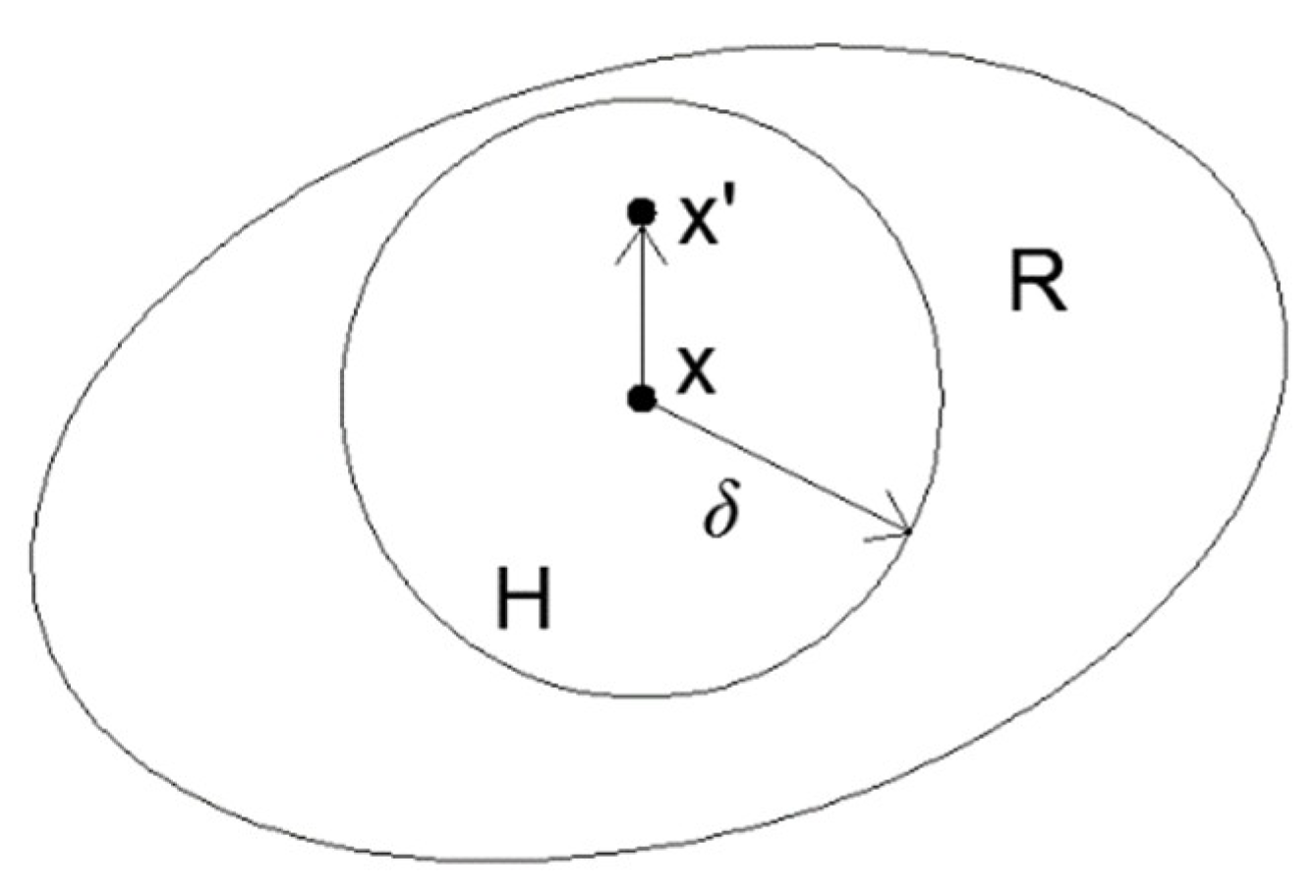
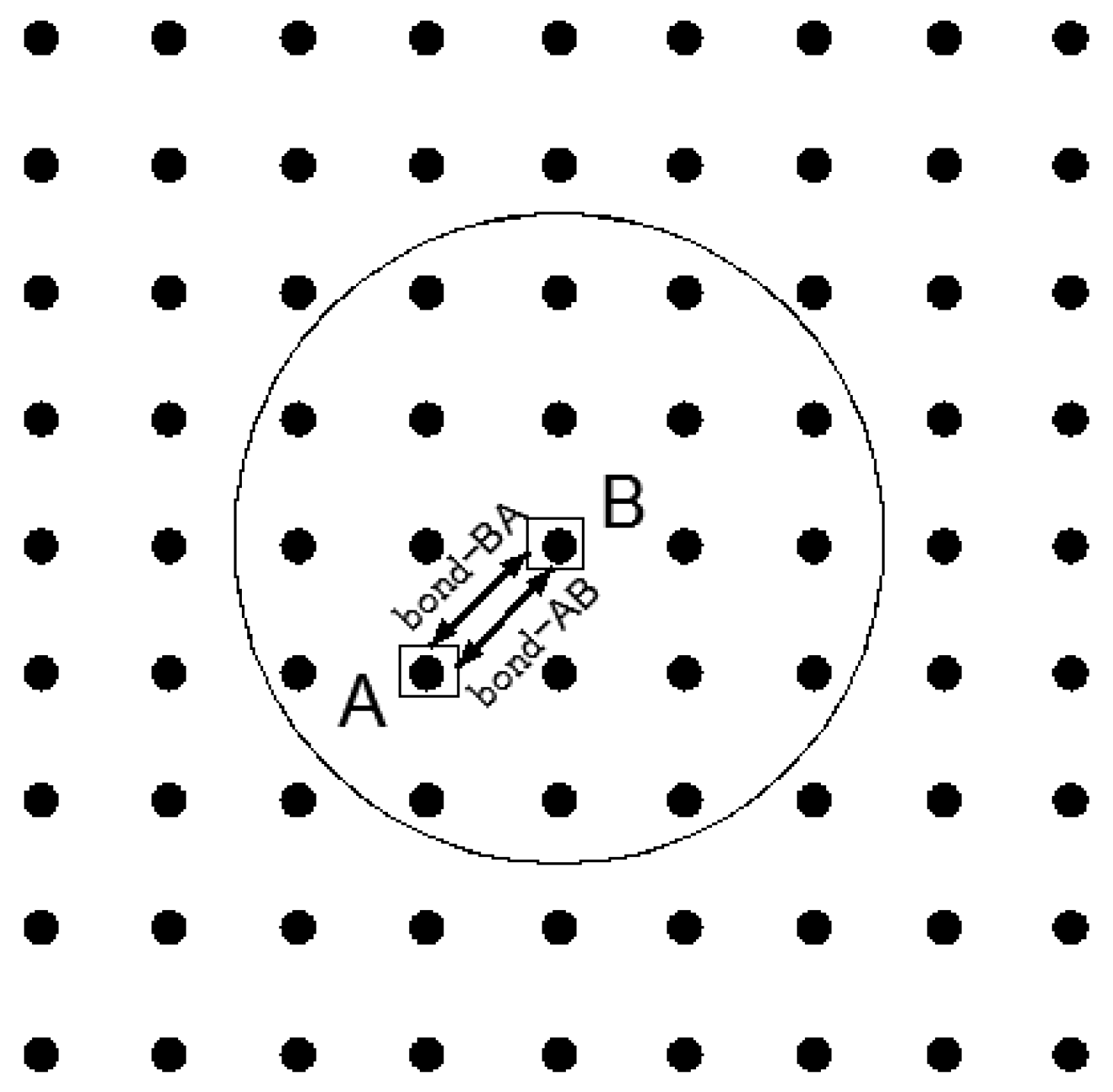
2.1. Basic Review of PD Theory for Elastic Brittle Materials

The PD method is a non-local continuity method that divides the material into a finite number of discrete material points, and the material point pairs are connected with each other by means of interaction forces within a limited distance. In PD theory, these interactions are called bond interaction forces, which are given by
ρ u ¨ = H x f ( u ( x , t ) u ( x , t ) , x x ) d V x + b ( x , t )
where f is the interaction force between the material points x and x’, u is the displacement vector field, ρ is the material density, and b(x,t) is the volume force. This integral is defined in the area H, which is called the ‘horizon,’ as shown in Figure 1. This ‘horizon’ region is a circle with a radius δ, and we also call the δ ‘horizon’ [23].
For a micro-elastic brittle material, the interaction force function between the material points can be expressed by its scalar potential function w:
f ( η , ξ ) = w ( η , ξ ) η
Here, η = u’ – u is the relative displacement and ξ = x’ − x is the relative position. The micro-potential energy w represents the single-bond energy, and the micro-potential energy function given by the strain energy density is
W = 1 2 H x w ( η , ξ ) d V ξ
The 1/2 factor is included because each end point of the bond is only half the energy of the total bond. Thus, it is concluded that
w ( η , ξ ) = c s 2 ξ 2
Thus, the interaction function f of the paired particles given above has the following form:
f ( η , ξ ) = η + ξ η + ξ c ( ξ ) s ξ δ
where ξ = ξ , s = ξ + η ξ ξ represents the elongation of the bond, and the function c represents the bond modulus function, which contains the material properties and determines the bonding elastic stiffness. In 2D structures, the constant micro-modulus function is
c = 6 E π δ 3 ( 1 ν )
where E, ν, and δ denote the modulus elasticity of the material, the Poisson’s ratio, and the horizon size, respectively. For the 2D bond-based PD model of an isotropic and homogeneous material under plane stress conditions, the Poisson’s ratio is ν = 1/3. The influence of the Poisson’s ratio ν on the fracture of FGMs is almost negligible [32]. Accordingly, in this paper, the bond-based PD model is used and the Poisson’s ratio ν is 1/3. According to the method of calculating micro-modulus functions [33] in 1D, we concluded that, in 2D, the conical micro-modulus function under plane stress [24] is obtained by the following:
c = c 1 ( 1 ξ δ ) = 24 E π δ 3 ( 1 ν ) ( 1 ξ δ ) .
The PD theory mainly focuses on dynamic fracture and failure theory. When the deformation within the horizon of the material point x exceeds the critical value, the PD bond between the material points is broken and the point fails. The critical length s0 can be calculated by the fracture energy of materials. In 2D structures, the fracture energy G0 is the following:
G 0 = 2 0 δ z δ 0 cos ( z ξ ) ( c s 0 2 ξ 2 ) ξ d θ d ξ d z .
By equating G0 to the work done in a PD material, the critical length s0 is
s 0 = 4 π G 0 9 E δ
for the constant micro-modulus function, and
s 0 = 5 π G 0 9 E δ
for the conical micro-modulus function. The critical relative elongation depends on the properties of the material and the ‘horizon’ δ.

2.2. PD Model for FGM

In this work, FGMs are understood as following an elastic model of local homogenization of material properties, where the density, elasticity modulus, and fracture toughness of material are constant. On the basis of local homogenization, the fracture theory of homogeneous materials is applied to inhomogeneous materials, such as composite materials [26], composite fiberboard materials [27], FGMs [31], and so on. For FGMs, we use the fracture criterion of the maximum energy release rate to calculate the fracture energy, which is given by the following formula:
G 0 = K IC 2 E
KIC and E represent the fracture toughness and elastic modulus of the crack tip of an FGM, respectively.
Since FGMs are not homogeneous materials, the above Equations (6)–(10) do not apply to FGMs, but are applicable locally. Cheng et al. [34] proposed a pair-bond principle, based on PD theory, in FGM as a heterogeneous material. They pointed out that two parallel bonds are used to replace the bonds between the original material points. If one of the bonds breaks, then the other bond will break at the same time. The validity and feasibility of the pair-bond PD theory have been well verified in FGM fracture simulations. In this paper, we use the pair-bond PD theory to study the dynamic fracture mechanism of FGM coating components.
For FGMs, the pair-wise interactions in bond-based PD are modified and two parallel bonds are introduced to replace the interaction between two material points, as shown in Figure 2. The bond between material points A and B becomes two parallel bonds. In the initial configuration, the length between material points A and B is s, and the bond length is s’ after the deformation.

2.2.1. Determination of Micro-Modulus Function c

Since material points A and B are connected by two parallel bonds, the energy of point A and the energy of point B each represent half of the total energy. It is defined that the micro-modulus function of material A is CA, and the micro-modulus function of material B is CB; obviously, the constant micro-modulus function C of the two parallel bonds is
c A = 12 E A π δ 3 ( 1 υ ) ( 1 ξ δ )
c B = 12 E B π δ 3 ( 1 υ ) ( 1 ξ δ )

2.2.2. Determination of the Interaction Function f

For the interaction function between two material points, the interaction function of material point A on the role of material point B is expressed as fAB, and the interaction function of material point B on the role of material point A is expressed as fBA. The interaction between material point A and material point B is then denoted by f. Thus,
f A B = { η + ξ η + ξ c A B s A B , ξ δ 0 , ξ > δ
f BA = { η + ξ η + ξ c BA s BA , ξ δ 0 , ξ > δ .

2.2.3. Critical Relative Elongation s0

The critical relative elongation is the fracture criterion used to measure the bonds among the material points. The critical relative elongation of the bond AB is sAB, and the critical relative elongation of the bond BA is sAB. These can be described as
s AB = 5 π G AB 9 E AB δ
s BA = 5 π G BA 9 E BA δ
It is only when the two bonds between point A and point B are broken that there is no bond between point A and point B.

3. Convergence Studies in Dynamic Crack Branching of FGMs

A PD model of FGMs has been verified [31,34], and the convergence of different stresses and different geometric sizes has been studied. In this section, the convergence of PD models is achieved by focusing on the problem where there is a pre-crack in an FGM sample under tensile stress load on the upper and lower surfaces.

3.1. Problem Setting

We considered a thin FGM rectangular plate with dimensions of 40 × 20 mm2 and a crack length of 20 mm. The geometric size and boundary conditions are shown in Figure 3. In addition, no other boundary conditions existed. The constant micro-modulus function (Equation (10)) was used in this section. The material composition of the FGM rectangular plate was epoxy mixed with a certain amount of glass to make its mechanical properties change step by step. The mechanical properties of the material parameters are shown in Table 1. The values of the density, elastic modulus, and fracture toughness of the FGM coating were taken from the results of Kirugulige and Tippur [7]. The gradient form of FGM was changed to its exponential form, a method that has been adopted by many researchers in previous studies [8]. In this section, the PD convergence of the FGM rectangular plates in exponential gradient form was investigated to further prove the feasibility of the PD method for studying crack bending of gradient materials under dynamic loading conditions.

3.2. δ-Convergence of FGM Samples

For the δ-convergence, we selected m = 4 (m is the ratio between the horizon size and Δx) and horizon sizes of δ = 0.8 mm (Δx = 0.2 mm), δ = 1.0 mm (Δx = 0.25 mm) and δ = 1.33 mm (Δx = 0.33 mm). Note that Δx is the grid spacing, and all models had uniform grid spacing. A uniform time step size of Δt = 25 ns was used, and a uniform tensile stress of σ = 2.5 MPa was applied to the FGM models in this section. It should be noted that when an FGM is used as a coating material, it is affected by coating thickness, so we refined the grid as much as possible to make sure that there were enough nodes to maintain the consistency of the mechanical property parameters of the material. The crack paths of the FGM samples at t = 80 μs are compared in Figure 4. The critical relative elongation s0 also changed with the δ decrease (Equations (9) and (10)). Moreover, the crack paths were not different as the δ decreased, but became clearer and clearer.

3.3. m-Convergence of FGM Samples

For the m-convergence, the FGM model and boundary conditions selected were the same as for the δ-convergence. We selected a fixed horizon size of δ = 1 mm, and respectively used m = 3 (Δx = 0.33 mm), m = 4 (Δx = 0.25 mm), and m = 5 (Δx = 0.2 mm). A uniform time step size of Δt = 25 ns was used. The crack paths of PD simulation in t = 80 μs are shown in Figure 5. With an increase in the grid density, m-convergence took place, causing dynamic crack growth in terms of the crack path and crack velocity. When there were enough nodes within the horizon range (m > 4), the crack path did not change further with an increase in grid density.
Large m values required a higher calculation cost, but the results were not affected. In the later simulation study, we chose m = 4, which was a good choice.

3.4. Δt-Convergence of FGM Samples

The time integral algorithm adopted for the PD motion equation was the Velocity–Verlet algorithm [23]:
u n + 1 2 = u n + u n Δ t 2
u n + 1 = u n + u n + 1 2 Δ t
u n + 1 = u n + 1 2 + u n + 1 n Δ t 2
where u, u’ and u’’ denote the displacement, velocity, and acceleration, respectively. Δt is the time step size per iteration. Silling pointed out that a computationally stable time step size Δt should satisfy [23]
Δ t < 2 ρ i V i c
Bobrau studied the effect of the brittle fracture of homogeneous rocks on the convergence of the PD model using a time step size of Δt = 25 ns, which is considered to be a stable time step for the finest models [24]. Here, we studied the convergence of the time step size for FGM samples to determine the optimal stable time step for the FGM model.
For the convergence study of time steps, we selected a horizon size of δ = 1 mm, a grid spacing of Δx = 0.25 mm (m = 4), and time step sizes for comparison of Δt = 10, 20 and 25 ns. The crack paths of the FGM samples in various Δt were compared at t = 80 µs, as shown in Figure 6. The models with the time step size of Δt = 25 ns had a larger bending phenomenon after t = 62 μs, but the crack paths with Δt = 10 and 20 ns were very similar. Considering the calculation cost, the time step size Δt = 20 ns was shown to be a good choice, as it is a precise and stable explicit central difference method.
Based on the PD convergence research of FGMs, we adopted these parameters with δ = 1.0 mm, m = 4, and Δt = 20 ns to balance the computational cost and accuracy requirements after the numerical simulation of the FGM coating components.

4. Simulation of FGM Coating—Substrate

There have been many studies on the dynamic fracture of homogeneous materials based on the PD model [24,25,26], and the PD model has also been used to analyze the dynamic fracture behavior of FGMs [31]. The convergence of the PD method was demonstrated in an FGM analysis that included damage, fracture, and thermal stress by Liu et al. [34]. In this paper, the crack propagation and deflection of FGM coatings with different forms of gradient are presented.

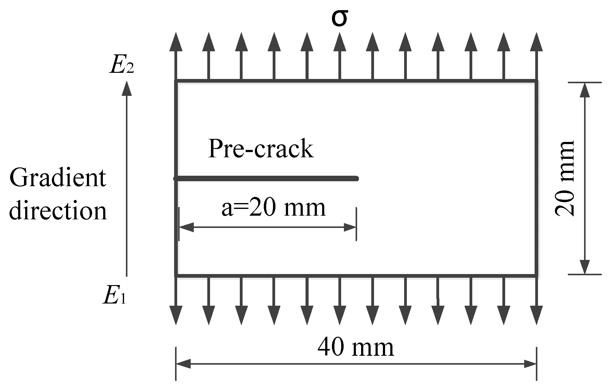
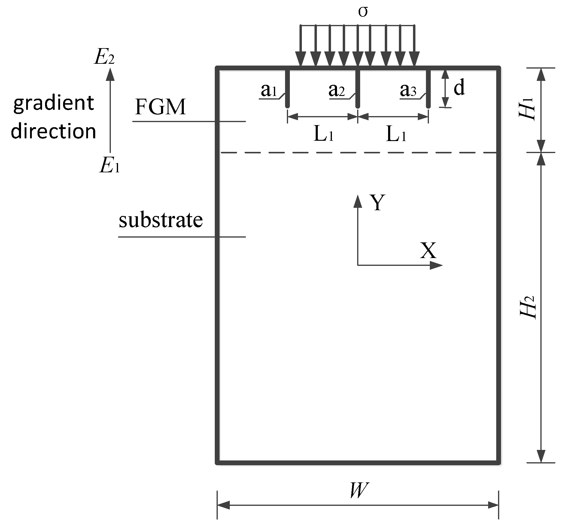
4.1. Problem Setting

In this section, consider a specimen in which the FGM coating is bonded to a homogeneous elastic substrate. The dimensions of the specimen are 40 mm × 80 mm. In the specimen, there are three cracks, each having a length of a1 = a2 = a3 = 5 mm, and the distance between adjacent cracks is L1 = 10 mm. The three cracks are perpendicular to the surface of the coating and are symmetrically arranged about the y axis, wherein the intermediate cracks are distributed along the y axis. Considering the existence of various complex cracks in reality, here, we only provide a simplified simulation. Based on the indentation test, we chose the superpositions of symmetric vertical cracks and central cracks. An impact load was applied to the upper surface of the specimen. The impact load had a range of 16 mm and was symmetrically distributed about the y axis. The specimen size, crack location, and loading location are shown in Figure 7; otherwise, no other boundary conditions existed. For the sake of simplicity of the simulation, we assumed that the coating thickness was H1 = 10 mm and the substrate thickness was H2 = 70 mm. In this study, the substrate used was an epoxy material with the same material properties as the lower surface of the FGM coating. The coating used was an FGM coating material made of glass/epoxy, in which the epoxy was attached to the substrate and the glass was exposed to the outside. It was assumed that the interface adhesion between the FGM coating and the homogeneous substrate was an ideal bond. The mechanical properties of the FGM coating–substrate specimen are listed in Table 1.

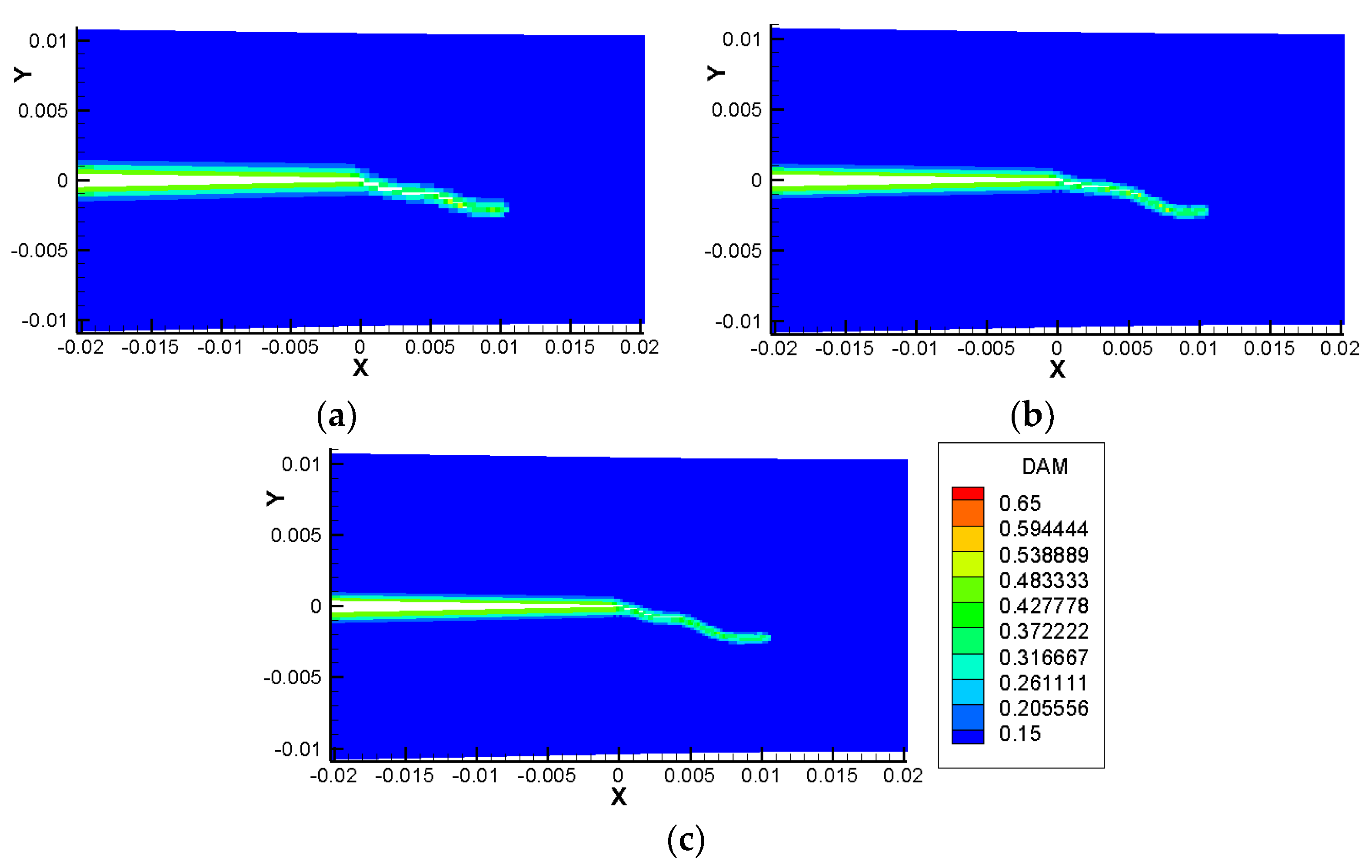
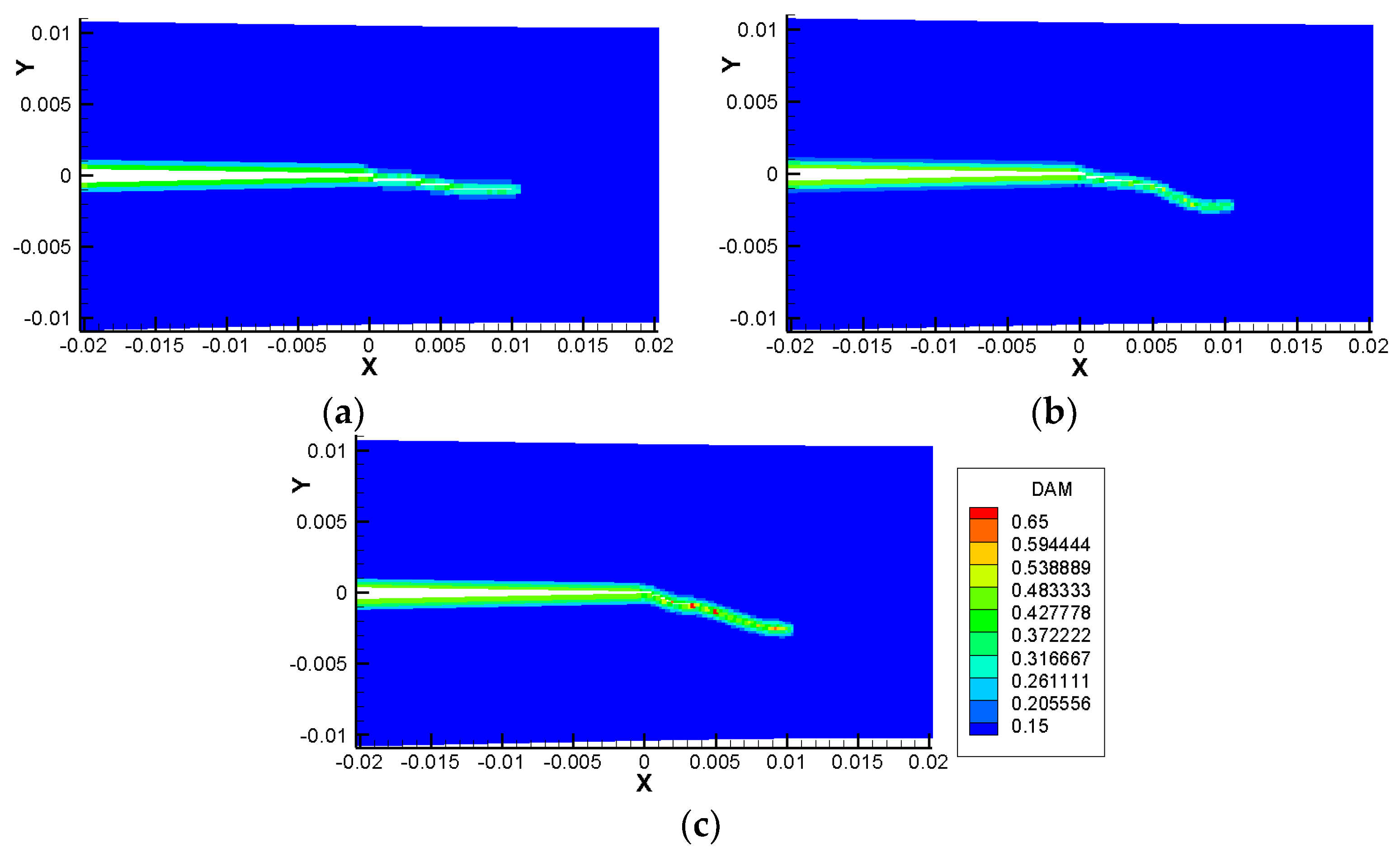
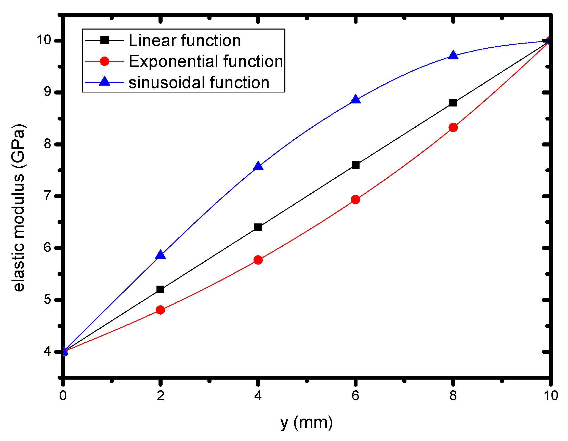
4.2. Crack Propagation and Deflection of the FGM Coating Corresponding to Different Gradient Forms

Based on the difficulty of discontinuity assumptions, many previous experiments and finite element simulations in FGMs have assumed that the properties of the elastic modulus in FGMs are exponential [7,8,19]. The PD theory was used to analyze the FGM model with arbitrarily changed gradient forms in this paper. The influence of diverse gradient forms in the FGMs was demonstrated by simulating the growth behavior of cracks with different gradient functions under dynamic loading conditions. In order to investigate the influence of the gradient forms of the material elastic parameters, it was assumed that the material parameters of the FGM changed according to the following three functional forms:
E = E 1 + α 1 y
E = E 1 e α 2 y
E = E 1 + ( E 2 E 1 ) sin ( α 3 y )
where α1, α2, and α3 are the variable parameters of the elastic modulus, which are related to the boundary value of the FGM coating. The variation in the three gradient functions of the FGM coating is shown in Figure 8. Similarly, the density and fracture toughness of the FGM coating also have these three forms. The forms of density are as follows:
Linear   functions :   ρ = ρ 1 + β 1 y
Exponential   function :   ρ = ρ 1 e β 2 y
Sin usoidal   function :   ρ = ρ 1 + ( ρ 2 ρ 1 ) sin ( β 3 y ) .
Additionally, the forms of the fracture toughness have
Linear   functions :   K IC = ρ 1 + γ 1 y
Exponential   function :   K IC = K IC 1 e γ 2 y
Sin usoidal   function :   K IC = K IC 1 + ( K IC 2 K IC 1 ) sin ( γ 3 y )
where β1, β2, and β3 are the variable parameters of the elastic modulus, and γ1, γ2, and γ3 are the variable parameters of fracture toughness. For this example, the values of E1, E2, ρ1, ρ2, KIC1, KIC2 are expressed in Table 1.
The effects of the gradient functions of the FGM coating on crack propagation were shown to be conducted. Some snapshots at 100 μs are shown in Figure 9. The impact loading applied to the coating surface was σ = 48 MPa, and the duration of the loading was t = 100 μs. As shown in Figure 9, the fracturing patterns were captured when the duration of the impact loading reached 100 μs. It can be observed from Figure 9 that among the three cracks, the crack on the right side was deflected to the right, the crack on the left side was extended to the left, and the crack in the middle was vertically expanded downward without deflection. It was also found that there was little difference in the crack propagation tendencies for different gradient function forms. This means that the effect of the gradient form on crack propagation in FGMs is very limited. Since the applied impact loading and the pre-cracks were symmetrically distributed, the intermediate crack propagated vertically downward and did not deflect to the left or right sides of the specimen. Figure 10 shows some snapshots for elastic energy density in the load duration. As expected, the highest elastic energy density was ahead of the crack tips, especially in the intermediate crack tip. It can also be found from Figure 10 that when the cracks propagated near the transition interface between the coating and the substrate, the stress concentration always occurred at the crack tips, especially at the tip of the intermediate crack.
As we know, FGMs are heterogeneous materials, of which the properties change continuously in a particular direction. The range of changes in material properties may affect the crack propagation in an FGM coating system. A functionally graded material coating structure with three vertical boundary cracks was considered, as shown in Figure 7. In the gradient layer, the material parameters of the upper and lower surfaces of the functionally gradient coatings are shown as E2 and E1, respectively. The function curve between the elastic modulus and coordinate y are plotted in Figure 11 for several specimens when E = E1 = 4 GPa and E2/E1 = 0.5, 2.5, 5, and 10, respectively. The applied impact loading was σ = 44.5 MPa and the duration of the load was t = 100 μs. The material properties in the specimen differed from sample to sample, though their gradient forms were all exponential functions.
The volume fraction content of an FGM coating has a certain effect on its overall performance, which is an important aspect of FGM performance. Tilbrook and his coworkers observed the pores and crack path of FGMs with different volume fractions by electron micrographs [35]. Figure 12 shows some snapshots of crack maps of FGM coatings with different E2/E1 at 100 μs. It can be seen that whether the ratio was E2/E1 = 2.5, 5, or 10, the crack propagation path was basically similar, but the propagation rate was different. When E2/E1 = 5, the two cracks extended to the edge of the specimen, but when E2/E1 = 2.5 or 10, the crack did not yet extend to the edge of the specimen, while when E2/E1 = 0.5, the coating was destroyed under impact loading. The contours of elastic energy density corresponding to Figure 12 at the same time are shown in Figure 13. For ease of comparison, the coating structure was also calculated when the coating consisted of homogeneous materials with the same geometry and loading conditions as the FGM coating, as shown in Figure 14. It can be seen from Figure 14 that the deflection angle of the crack in the uniform material coating was larger than that in the gradient coating, and the propagation range of the crack in the uniform material substrate was longer. This means that the fracture resistance of the coating structure can be improved by selecting suitable gradient coatings [36].

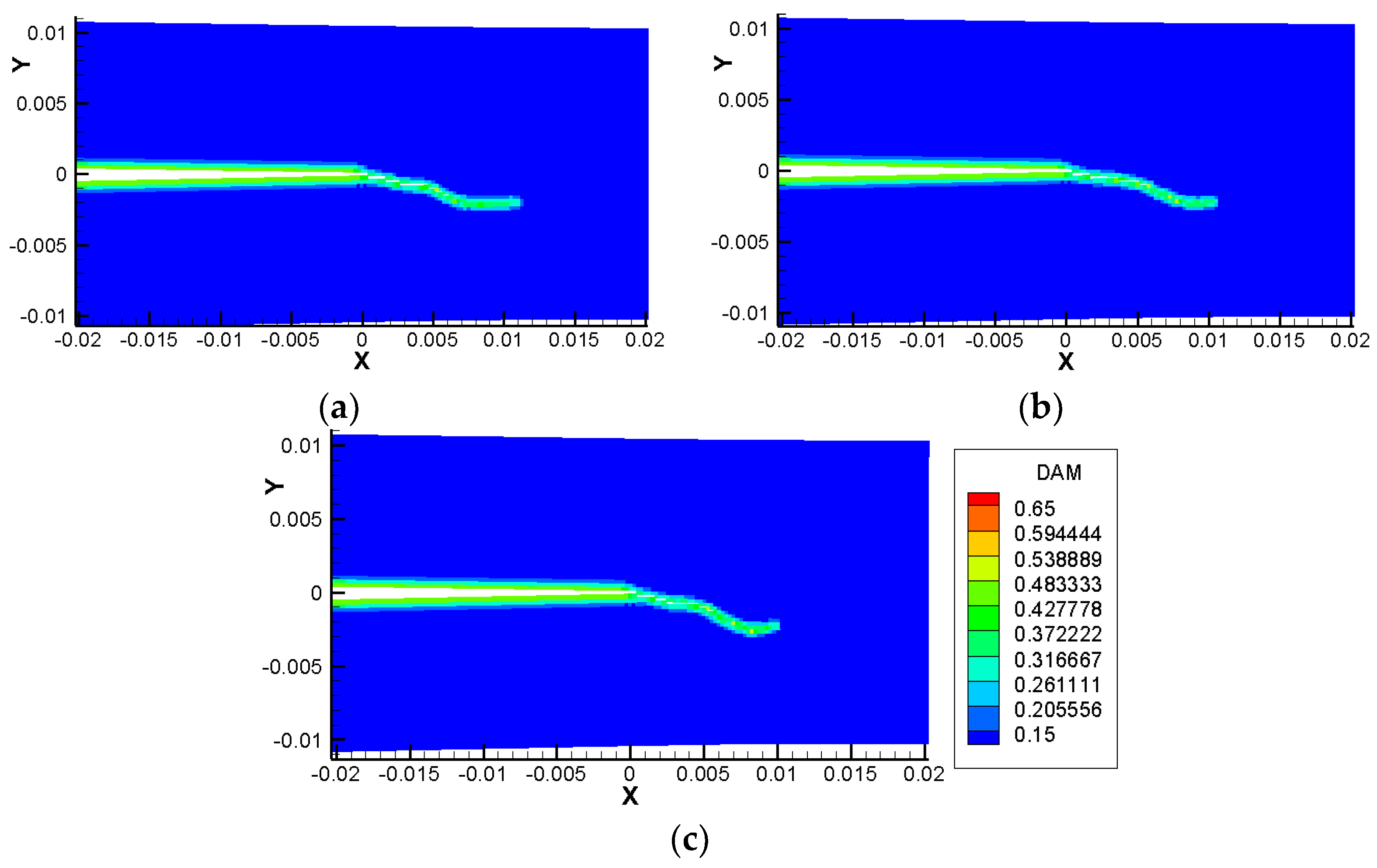
4.3. Crack Propagation and Deflection of FGMs Corresponding to Different Coating Thicknesses

When FGMs is used as a coating material, the coating thickness is also an important factor for its dynamic fracture. Tilbrook and his colleagues demonstrated the fracture problem of randomly oriented cracks of FGMs about the probability density function of mixed mode SIFs [35]. The value of the stress intensity factor K is related to the material thickness, and the coating thickness also affects the stress of the crack tip. Here, the dynamic fracture behavior of different gradient coating thicknesses on the substrate components was investigated. The geometry and the boundary conditions of the FGM coating structure are shown in Figure 7. The coating thicknesses used in this simulation were H1 = 8, 10 and 12 mm, H2 = 70 mm, and W = 40 mm. The stress load application conditions were σ0 = 41 MPa, as shown in Figure 15; the duration of the load was t = 100 μs. The crack length was d = 4 mm, and the distance between adjacent cracks was L1 = 10 mm. Some snapshots of the crack maps and the elastic strain density of the FGM coating with different coating thickness at 100 μs with σ0 = 41 MPa are shown in Figure 16 and Figure 17, respectively. It was found that the deflection angle of the crack was almost the same under three sizes of coating thickness, but when the coating thickness was 12, the crack first extended to the left and right boundaries, and when the coating thickness was 8, the crack propagation distance was the smallest. Goyat and Verma chose an FGM coating with the power law index, and pointed out that the thickness of the coating largely contributes to the reduction of the stress concentration factor [17]. It was also found that the sample with a coating thickness of 8 mm had a smaller range of strain energy density and less damage was done to the component under the same conditions. Although the strain energy density of the sample with a coating thickness of 12 mm was minimal, the crack extension was indeed the fastest. It was seen that the 12 mm coating sample did not really exert its full energy effect. This means that the coating thickness also has a great influence on the generation of cracks. Due to the cost and complexity of FGM preparation, an appropriate coating thickness is sufficient to protect the substrate from damage.

5. Conclusions

In this paper, the bond-based PD theory was employed to discuss the dynamic fracture behavior of surface cracks in FGM coating substrate specimens. The influences of the gradient pattern, coating thickness, and elastic gradient ratio of the upper surface and the lower surface of the FGM coating on crack propagation and deflection in the FGM coating substrate under dynamic load were analyzed. The numerical results showed that the surface cracks in the FGM coating substrate specimen always spread to the two sides under the impact load of the upper center, no matter how the gradient formed. The gradient function form of FGM had little effect on the crack propagation in the FGM coating. Because of the symmetry of the compressive load and crack locations, the middle crack was never deflected due to the stress concentration. The different elastic modulus ratios of gradient coatings and coating thicknesses showed no relation to the crack paths, but the degree of crack curing was not the same. The coating thickness was shown the most significant effect on the cracks. In future research, the gradient form of FGM coating components will be investigated in order to find a suitable gradient form that can better play the role of an FGM coating.

Author Contributions

Methodology, Z.C.; Supervision, Z.C.; Writing–original draft, Y.Z.; Writing–review & editing, Z.C. and H.F.

Funding

This work was supported by the Natural Science Foundation of China (Nos. 11472248, 11872339, 51708510) and the Natural Science Foundation of Henan Province (No. 182300410221).

Conflicts of Interest

The authors declare no conflict of interest.

References

  1. Gu, P.; Asaro, R.J. Cracks in functionally graded materials. Int. J. Solids Struct. 1997, 34, 1–17. [Google Scholar] [CrossRef]
  2. Zuiker, J.R. Functionally graded materials: Choice of micromechanics model and limitations in property variation. Compos. Eng. 1995, 5, 807–819. [Google Scholar] [CrossRef]
  3. Pompe, W.; Worch, H.; Epple, M.; Friess, W.; Gelinsky, M.; Greil, P.; Hempel, U.; Scharnweber, D.; Schulte, K. Functionally graded materials for biomedical applications. Mater. Sci. Eng. A 2003, 362, 40–60. [Google Scholar] [CrossRef]
  4. Zhang, Z.; Paulino, G.H. Wave propagation and dynamic analysis of smoothly graded heterogeneous continua using graded finite elements. Int. J. Solids. Struct. 2007, 44, 3601–3626. [Google Scholar] [CrossRef] [Green Version]
  5. Li, H.; Lambros, J.; Cheeseman, B.A.; Santare, M.H. Experimental investigation of the quasi-static fracture of functionally graded materials. Int. J. Solids Struct. 2000, 37, 3715–3732. [Google Scholar] [CrossRef]
  6. Zhang, Z.; Paulino, G.H. Cohesive zone modeling of dynamic failure in homogeneous and functionally graded materials. Int. J. Plast. 2005, 21, 1195–1254. [Google Scholar] [CrossRef]
  7. Kirugulige, M.; Tippur, H.V. Mixed-mode dynamic crack growth in a functionally graded particulate composite: Experimental measurements and finite element simulations. J. Appl. Mech. 2008, 75, 883–890. [Google Scholar] [CrossRef]
  8. Jamia, N.; El-Borgi, S.; Fernandes, R.; Vegamoor, V. Analysis of an arbitrarily oriented crack in a functionally graded plane using a non-local approach. Theor. Appl. Fract. Mech. 2016, 85, 387–397. [Google Scholar] [CrossRef]
  9. Jin, Z.H.; Batra, R.C. Interface cracking between functionally graded coatings and a substrate under antiplane shear. Int. J. Eng. Sci. 1996, 34, 1705–1716. [Google Scholar] [CrossRef]
  10. Cai, H.; Bao, G. Crack bridging in functionally graded coatings. Int. J. Solids Struct. 1998, 35, 701–717. [Google Scholar] [CrossRef]
  11. Guler, M.A.; Erdogan, F. Contact mechanics of graded coatings. Int. J. Solids Struct. 2004, 41, 3865–3889. [Google Scholar] [CrossRef]
  12. Almeida, C.A.; Albino, J.C.R.; Menezes, I.F.M.; Paulino, G.H. Geometric nonlinear analyses of functionally graded beams using a tailored Lagrangian formulation. Mech. Res. Com. 2011, 38, 553–559. [Google Scholar] [CrossRef]
  13. Kim, J.H.; Paulino, G.H. Mixed-mode fracture of orthotropic functionally graded materials using finite elements and the modified crack closure method. Eng. Fract. Mech. 2002, 69, 1557–1586. [Google Scholar] [CrossRef]
  14. Kim, J.H.; Paulino, G.H. Simulation of crack propagation in functionally graded materials under mixed-mode and non-proportional loading. Mech. Mater. Des. 2004, 1, 63–94. [Google Scholar] [CrossRef]
  15. Erdogan, F. Fracture mechanics of functionally graded materials. Compos. Eng. 1995, 5, 753–770. [Google Scholar] [CrossRef]
  16. Guo, L.C.; Wu, L.Z.; Zeng, T.; Ma, L. The dynamic fracture behavior of a functionally graded coating-substrate system. Compos. Struct. 2004, 64, 433–441. [Google Scholar] [CrossRef]
  17. Goyat, V.; Verma, S.; Garg, R.K. Reduction in stress concentration around a pair of circular holes with functionally graded material layer. Acta Mech. 2018, 229, 1045–1060. [Google Scholar] [CrossRef]
  18. Rezaei, S.; Wulfinghoff, S.; Reese, S. Prediction of fracture and damage in micro/nano coating systems using cohesive zone elements. Int. J. Solids Struct. 2017, 121, 62–74. [Google Scholar] [CrossRef]
  19. Rousseau, C.E.; Tippur, H.V. Compositionally graded materials with cracks normal to the elastic gradient. Acta Mater. 2000, 48, 4021–4033. [Google Scholar] [CrossRef]
  20. Marur, P.R.; Tippur, H.V. Numerical analysis of crack-tip fields in functionally graded materials with a crack normal to the elastic gradient. Int. J. Solids Struct. 2000, 37, 5353–5370. [Google Scholar] [CrossRef]
  21. Abanto-Bueno, J.; Lambros, J. An experimental study of mixed mode crack initiation and growth in functionally graded materials. Exp. Mech. 2006, 6, 179–196. [Google Scholar] [CrossRef]
  22. Silling, S.A. Reformulation of elasticity theory for discontinuities and long-range forces. J. Mech. Phys. Solids 2000, 8, 175–209. [Google Scholar] [CrossRef]
  23. Silling, S.A.; Askari, E. A meshfree method based on the peridynamic model of solid mechanics. Comput. Struct. 2005, 3, 1526–1535. [Google Scholar] [CrossRef]
  24. Ha, Y.D.; Bobaru, F. Studies of dynamic crack propagation and crack branching with peridynamics. Int. J. Fract. 2010, 162, 229–244. [Google Scholar] [CrossRef] [Green Version]
  25. Ha, Y.D.; Bobaru, F. Characteristics of dynamic brittle fracture captured with peridynamics. Eng. Fract. Mech. 2011, 78, 1156–1168. [Google Scholar] [CrossRef]
  26. Hu, W.; Ha, Y.D.; Bobaru, F. Peridynamic model for dynamic fracture in unidirectional fiber-reinforced composites. Comput. Methods Appl. Mech. Eng. 2012, 217–220, 247–261. [Google Scholar] [CrossRef]
  27. Hu, Y.L.; Carvalho, N.V.D.; Madenci, E. Peridynamic modeling of delamination growth in composite laminates. Compos. Struct. 2015, 132, 610–620. [Google Scholar] [CrossRef]
  28. Ha, Y.D.; Lee, J.; Hong, J.W. Fracturing patterns of rock-like materials in compression captured with peridynamics. Eng. Fract. Mech. 2015, 144, 176–193. [Google Scholar] [CrossRef]
  29. Qiao, P.Z.; Huang, D.; Zhang, Q. Damage and progressive failure of concrete structures using non-local peridynamic modeling. Sci. China Tech. Sci. 2011, 54, 591–596. [Google Scholar]
  30. Gu, X.; Zhang, Q.; Huang, D.; Yv, Y. Wave dispersion analysis and simulation method for concrete SHPB test in peridynamics. Eng. Fract. Mech. 2016, 160, 124–137. [Google Scholar] [CrossRef]
  31. Cheng, Z.; Zhang, G.; Wang, Y.; Bobaru, F. A peridynamic model for dynamic fracture in functionally graded materials. Compos. Struct. 2015, 133, 529–546. [Google Scholar] [CrossRef]
  32. Delale, F.; Erdogan, F. The crack problem for a nonhomogeneous plane. J. Appl. Mech. 1983, 50, 609–614. [Google Scholar] [CrossRef]
  33. Bobaru, F.; Yang, M.; Alves, L.F.; Silling, S.A.; Askari, E.; Xu, F. Convergence, adaptive refinement, and scaling in 1D peridynamics. Int. J. Num. Methods Eng. 2010, 77, 852–877. [Google Scholar] [CrossRef]
  34. Cheng, Z.; Liu, Y.; Zhao, J.; Feng, H.; Wu, Y. Numerical simulation of crack propagation and branching in functionally graded materials using peridynamic modeling. Eng. Fract. Mech. 2018, 191, 13–32. [Google Scholar] [CrossRef]
  35. Tilbrook, M.T.; Rutgers, L.; Moon, R.J.; Hoffman, M. Fatigue crack propagation resistance in homogeneous and graded alumina-epoxy composites. Int. J. Fatigue 2007, 29, 158–167. [Google Scholar] [CrossRef]
  36. Guo, L.; Huang, S.; Zhang, L.; Jia, L. The interface crack problem for a functionally graded coating-substrate structure with general coating properties. Int. J. Solids Struct. 2018, 146, 136–153. [Google Scholar] [CrossRef]
Figure 1. Any point x in R interacts directly with point x’ in horizon H by the bond.
Coatings 09 00062 g001
Figure 2. The interaction of parallel bonds between the material points A and B.
Coatings 09 00062 g002
Figure 3. Specimen geometric and boundary conditions.
Coatings 09 00062 g003
Figure 4. Crack path with different δ (m = 4) values using peridynamics (PD) models at 80 µs. (a) δ = 1.33 mm (Δx = 0.33 mm); (b) δ = 1.0 mm (Δx = 0.25 mm); (c) δ = 0.8 mm (Δx = 0.2 mm).
Coatings 09 00062 g004
Figure 5. Crack path with different m (δ = 1 mm) values using PD models at 80 µs. (a) m = 3 (Δx = 0.33 mm); (b) m = 4 (Δx = 0.25 mm); (c) m = 5 (Δx = 0.2 mm).
Coatings 09 00062 g005
Figure 6. Crack path computed with different time step sizes for δ =1 mm, Δx =0.25 mm and m = 4 at 80 µs: (a) Δt = 10 ns; (b) Δt = 20 ns, (c) Δt = 25 ns.
Coatings 09 00062 g006
Figure 7. Specimen geometric and boundary conditions.
Coatings 09 00062 g007
Figure 8. The variation of gradient properties of different FGM coatings.
Coatings 09 00062 g008
Figure 9. Crack propagation and deflection of an FGM coating substrate sample as a function of the different gradient parameters under a dynamic concentrated load: (a) linear function; (b) exponential function; (c) sine function.
Coatings 09 00062 g009
Figure 10. Contours of the elastic energy density as the cracks grow in the three gradient forms: (a) Linear function; (b) Exponential function; (c) Sine function.
Coatings 09 00062 g010
Figure 11. The ratio of the elastic moduli of different gradient coatings.
Coatings 09 00062 g011
Figure 12. Snapshots of the crack maps in different FGM specimens with the elastic modulus as an exponential function at 100 μs: (a) E2/E1 = 0.5; (b) E2/E1 = 2.5; (c) E2/E1 = 5; (d) E2/E1 = 10.
Coatings 09 00062 g012aCoatings 09 00062 g012b
Figure 13. Contours of elastic energy density in the FGM coating with the elastic ratio at 100 μs: (a) E2/E1 = 0.5; (b) E2/E1 = 2.5; (c) E2/E1 = 5; (d) E2/E1 = 10.
Coatings 09 00062 g013
Figure 14. The surface crack growth of the homogeneous coating substrate sample at t = 100 μs under impact load: (a) crack map; (b) elastic energy density.
Coatings 09 00062 g014
Figure 15. Applied load and time.
Coatings 09 00062 g015
Figure 16. Propagation and deflection of cracks in FGM coatings with different coating thickness: (a) 8 mm; (b) 10 mm; (c) 12 mm.
Coatings 09 00062 g016
Figure 17. Contours of the elastic energy density in FGM coatings with different thicknesses: (a) 8 mm; (b) 10 mm; (c) 12 mm.
Coatings 09 00062 g017
Table 1. Material parameters of functional gradient material (FGM) coating samples.
MaterialElastic Modulus
E (GPa)
Density ρ
(kg m−3)
Poisson Ratio
ν
Fracture Toughness
KIC (MPa·m1/2)
Lower FGM l411750.331.4
Upper FGM1017500.332.2

