Article

Preparation and Corrosion Resistance of ETEO Modified Graphene Oxide/Epoxy Resin Coating

Key Laboratory of Automobile Materials, Ministry of Education, College of Materials Science and Engineering, Jilin University, Changchun 130022, China
*
Author to whom correspondence should be addressed.
Coatings 2019, 9(1), 46; https://doi.org/10.3390/coatings9010046
Submission received: 10 December 2018 / Revised: 8 January 2019 / Accepted: 11 January 2019 / Published: 15 January 2019
(This article belongs to the Special Issue Surface Chemical Modification)

Abstract

:
Improving the corrosion resistance of epoxy resin coatings has become the focus of current research. This study focuses on synthesizing a functionalized silane coupling agent (2-(3,4-epoxycyclohexyl)ethyl triethoxysilane) to modify the surface of graphene oxide to address nanomaterial agglomeration and enhance the coating resistance of the epoxy resin coating to corrosion by filling the coating with functionalized graphene oxide. Functionalized graphene oxide and coatings filled with functionalized graphene oxide were characterized by Fourier transform infrared spectroscopy, X-ray diffraction, X-ray photoelectron spectroscopy, scanning electron microscopy, and transmission electron microscopy. The corrosion performance of each coating was studied by electrochemical impedance spectroscopy and a salt spray test. Results showed that the incorporation of functionalized graphene oxide enhances the corrosion protection performance of the epoxy composite coating, and the composite coating exhibited the best anticorrosion performance when the amount of functionalized graphene oxide was 0.7 wt %.

1. Introduction

Corrosion protection has gained considerable attention because corrosion has brought great harm to the industry [1]. At present, metal protection methods are mainly categorized into alloy protection, electroplating protection, electrochemical protection, and organic coating protection [2]. Among them, organic coating protection is widely used in several industrial fields owing to its low price, easy construction and excellent performance [3]. An organic coating separates a corrosive medium from a metal substrate and protects the metal substrate with a filler added to the coating and to the film-forming material [4,5]. As a high performance resin, epoxy resin is widely used in aerospace, industrial manufacturing, construction, and chemical fields [6,7]. Epoxy-based coatings have high chemical resistance, good barrier properties, good adhesion, low film shrinkage, high cross-linking density, easy curing, and low toxicity and are thus used to replace highly toxic and carcinogenic zinc/chromate composite coating [8,9,10].
However, with the deteriorating environment and the diversity of production, pure epoxy resin anticorrosion coatings have become increasingly difficult to meet the requirements, which also limits the application of epoxy resin anticorrosion coating [11]. Therefore, methods for modifying epoxy resin coatings, including structural modification [12,13], rubber modification [14], resin modification [15], and filler modification [16,17,18,19,20,21,22,23] are necessary. During the curing, the volatilization of a solvent can lead to the appearance of micropores, microcracks and diffusion channels in the coatings. These defects cause the easy absorption of moisture and reduction of the barrier and the adhesion properties of the coatings, thereby accelerating corrosion [24,25]. For this problem, various fillers have been used as reinforcements to improve coating performance. The modification of epoxy resin coatings with fillers can reduce the costs of coating production and the shrinkage and fluidity of the coatings and improve the chemical stability, thermal conductivity and mechanical properties of the coatings. The commonly used fillers are roughly classified into three types, namely, flaky particles, fibrous fillers and nanomaterials. Flaky particles mainly include aluminum powder and mica flakes [26]. They increase the corrosion resistance and improve the wear resistance of the coating. Fiber-based fillers, like carbon fiber and glass fiber, have excellent thermal stability, corrosion resistance, wear resistance, low density, and good interfacial compatibility [27,28]. However, the length of fibers is extremely difficult to limit; hence, its application is still limited. Nanomaterials generally refer to materials that have at least one dimension in a three-dimensional space with a nanometer size (1–100 nm). The addition of nanomaterials to the coating greatly enhances the adhesion, mechanical properties and corrosion resistance of the latter [29].
As an excellent nanomaterial, graphene oxide (GO) has gradually demonstrated broad prospects and important functions in the field of coating fabrication. GOs have a highly specific surface area and unique properties [30,31] and can enhance the barrier and corrosion resistance of coatings. The distribution and compatibility of GO plays a decisive role in the performance of composite coatings. GOs have a strong van der Waals force and contain hydrophilic oxygen-containing groups on their surfaces and are thus incompatible with coating matrixes [32]. Moreover, these features result in agglomeration, which in turn increases the amount of micropores and microcracks. The large amount of oxygen-containing groups, that is, hydroxyl, carboxyl and epoxide groups [32], on GO surfaces can provide suitable reaction sites for modification. Therefore, surface modification of GO is a promising route to improve compatibility. Li et al. [33] studied the properties of silane-coupling-agent-modified GO composite epoxy resin coatings. Their results showed that modified GO remarkably enhanced the mechanical properties of epoxy resin.
Cyclohexene oxide and its derivatives are active chemical raw materials. They are easily soluble in alcohols, ketones and various organic solvents. The epoxide groups of the molecular structure in cyclohexene oxide are sufficiently active to participate in a variety of reactions. For example, it can react with curing agents containing amino groups in coatings. Cyclohexene oxide is also a good reactive diluent of epoxy resin, which can improve the compatibility with epoxy resin after modifying the fillers in the coating system. At present, there is little research on the modification of fillers by cyclohexene oxide and its derivatives. In this work, we synthesized a cyclohexene oxide-based silane coupling agent, namely 2-(3,4-epoxycyclohexyl)ethyl triethoxysilane (ETEO), by hydrosilylation reaction [34], and used it to modify the surface of GO. Then, GO and the modified GO were added into epoxy resin coatings, and the effects of the modified GO on mechanical properties and corrosion resistance of the epoxy resin composite coatings were investigated. Finally, we determined the optimum ratio of the epoxy resin coatings with different filler contents to obtain the composite coating with the best anticorrosion performance.

2. Materials and Methods

2.1. Materials

Karstedt catalyst solution, 4-vinyl-1-cyclohexene-1,2-epoxide (VCHO), triethoxysilane (TES), and graphite (99.95%, metal basis) were Aladdin products (Shanghai, China). Potassium permanganate, concentrated sulfuric acid, hydrogen peroxide, sodium nitrate, hydrochloric acid, and toluene were purchased from Beijing Chemical Works (Beijing, China). A commercially available epoxy resin (E-44) and polyamide curing agent (650) were supplied by Wuxi Dic Epoxy Co., Ltd., Wuxi, China. The steel panels (Q235, 80 mm × 40 mm × 0.2 mm) were purchased from Biuged Laboratory Instruments (Guangzhou) Co., Ltd., Guangzhou, China.

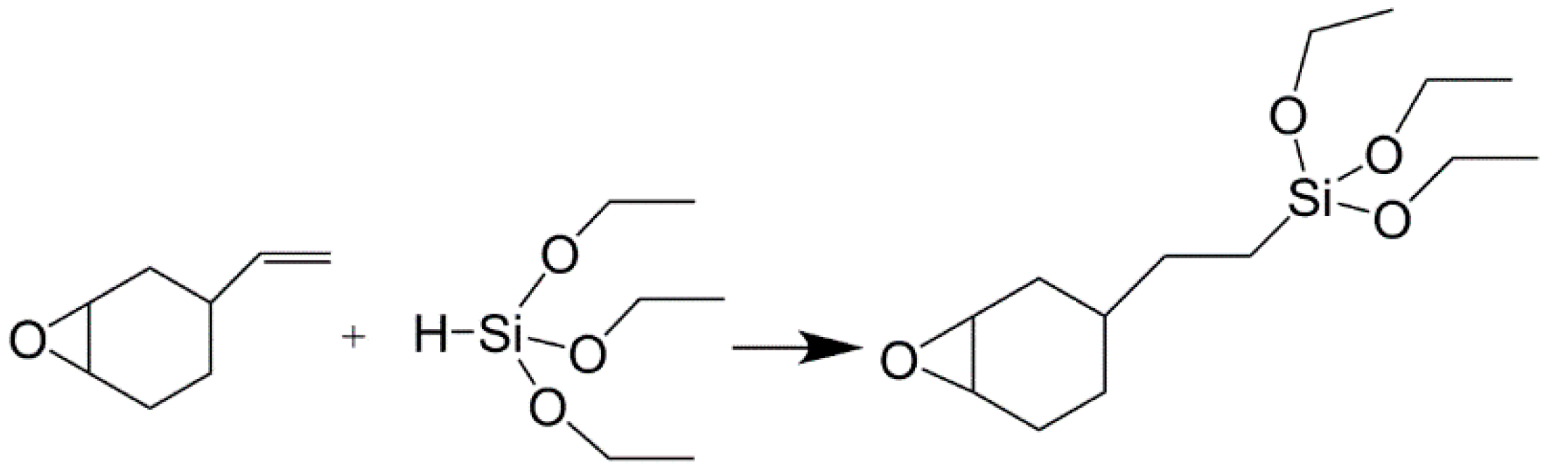
2.2. Preparation of 2-(3,4-Epoxycyclohexyl)Ethyl Triethoxysilane (ETEO)

ETEO was prepared as described in our previous work [34]. In short, ETEO was synthesized through a hydrosilylation reaction with VCHO and TES. The reaction equation is shown in Figure 1.

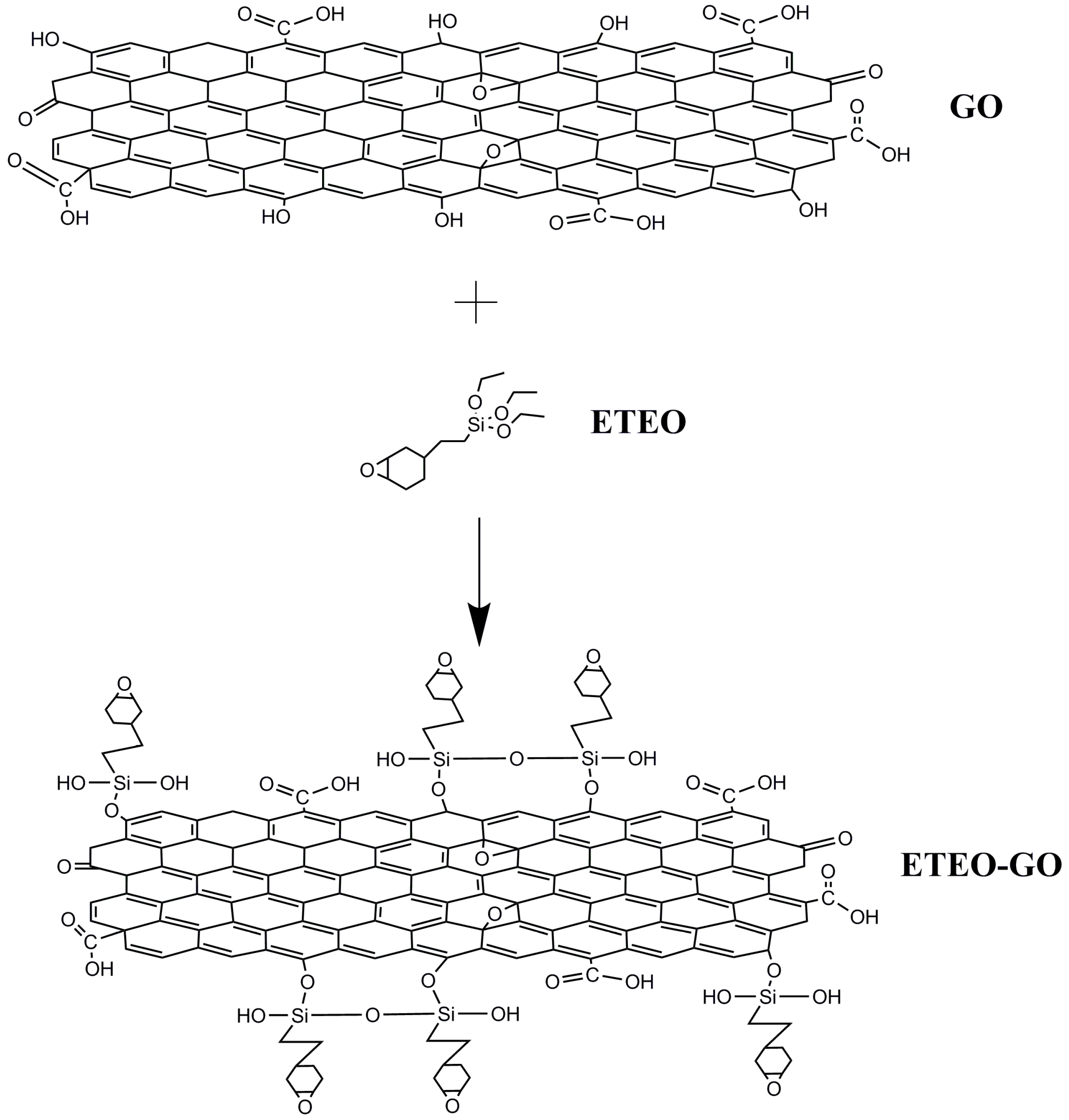
2.3. Preparation of ETEO-Modified GO (ETEO-GO)

In this experiment, the graphene oxide was prepared by the Hummers method [35]. GO (0.2 g) was ultrasonically mixed with deionized water (40 mL) for 1 h. Then, the suspension was placed in a water bath at 60 °C and continuously stirred. The obtained ETEO (1.2 g) was gradually added, and the system was reacted under reflux for 12 h. The suspension was filtered after the reaction, unreacted ETEO was washed away with deionized water, and the product was dried at 60 °C for 24 h. Figure 2 shows the diagram of the synthesis of ETEO-modified GO.

2.4. Preparation of Coatings

The metal substrate was wiped clean with ethanol and acetone and dried before spraying. The coatings were made by taking the desired quantity of filler (0.7 wt % GO and 0.1 wt %, 0.4 wt %, 0.7 wt %, and 1.0 wt % ETEO-GO) with epoxy resin. In addition, the pure epoxy coating (EP) was used as a blank control group. Then, a curing agent was added into the compound and stirred at a high speed for 30 min (Table 1). After spraying, the samples were kept at room temperature for 72 h and then cured in an oven at 60 °C for 4 h. The dry thickness of the coatings were 120 ± 10 μm.

2.5. Characterization

Fourier transform infrared spectroscopy (FTIR) was recorded using KBr disks on Fourier transform infrared spectrometer (Nicolet Nexus 670, Nicolet, Thermo Fisher Scientific, Waltham, MA, USA). In all cases, the scans were carried out in the spectral range from 4000 cm−1 to 400 cm−1 with a resolution of 4 cm−1. The phase crystalline structures of the GO and ETEO-GO were characterized by XRD analysis using Japanese D/max 2500PC X-ray diffractometer (Rigaku, Tokoy, Japan) with a scan range of 8°–90° and a scan speed of 5°/min. The chemical bonding of ETEO on the GO surface was studied by X-ray photoelectron spectroscopy (XPS, ESCALAB 250, American Thermoelectricity, Waltham, MA, USA) using Al-Kα as the source. The surface morphology of the GO and ETEO-GO and the cross-section morphology of the coatings were investigated by SEM (JSM-6700F, JEOL, Tokyo, Japan). The surface morphology was also studied by TEM (JEM-2100F, JEOL).

2.6. Mechanical Performance Test

The mechanical properties of the coating were investigated by hardness and impact resistance. The hardness of the coating was tested using a pencil hardness tester according to the GB/T 6739-2006 standard [36], and a pencil with a certain hardness was applied to the dried film. The scratches, indicated by the hardest pencil mark, do not cause damage to the coating film; the coating impact resistance was measured with a DuPont impactor according to ASTM-D2794 standard [37] and the test piece was placed face up under the instrument head. The test results were expressed in terms of the maximum drop height of the 1 kg weight that caused the coating to break.

2.7. Contact Angle Measurements

The contact angle of the coating was characterized using an OCA20 optical contact angle measuring instrument (Data physics, Filderstadt, Germany). The test environment was at room temperature, and the volume of a single drop of water was 2 µL. The value of each sample in the test was the average of three test points per plane, and the measurement accuracy was ±0.1°. The test procedure for all samples was performed after the water droplets were stable for 30 s.

2.8. Coating Electrochemical Impedance Test

The electrochemical impedance of the coating was tested using a PARSTAT 2273 electrochemical workstation (Ametek, Princeton, NJ, USA). The test frequency range was 105–10−2 Hz, the test voltage was 20 mV, the exposed area of the steel plate was 21 cm2 with the NaCl solution, and the electrolytic cell was a three-electrode electrolytic cell (the counter electrode was platinum electrode, the reference electrode was saturated calomel electrode).

2.9. Salt Spray Test

According to the “Neutral Salt Spray Test Standard” (GB/T 10125-1997 [38]), the coating was continuously sprayed using a salt spray corrosion test chamber (ZhongkeMeiqi Technology Co., Ltd., Beijing, China). The coated panel was placed in a test chamber at an inclination angle of 15°, and the etching solution was 5% aqueous NaCl solution, which was scribed at the surface of the coating to accelerate the observation of the degree of corrosion of the coating.

3. Results and Discussion

3.1. FTIR Analysis

To confirm the functionalization of GO sheets with ETEO, we examined the FTIR spectra of the GO and ETEO-GO samples, as shown in Figure 3. The FTIR spectrum of GO revealed the C–OH stretching as a broad peak at 3427 cm−1, the C=O stretching vibrations of carboxyl at 1730 and 1384 cm−1, and C=C skeletal vibrations at 1629 cm−1. After modification of GO with ETEO, the new bands appeared at 2923 and 1021 cm−1, which were assigned to the methylene of ETEO and the Si–O–C bands between GO and ETEO. It can still be seen that the stretching vibration of the epoxide group appeared at 1070 and 830 cm-1. The appearance of the above characteristic peaks proved that ETEO successfully modified GO.

3.2. XRD Analysis

The XRD spectra of GO and ETEO-GO samples are shown in Figure 4. The sharp diffraction peak appeared at 10.7°, which belonged to the (001) crystal face for the GO sample, indicating that the structure of GO was highly ordered [39]. From Bragg’s law, the interlayer distance of GO was 0.826 nm. The diffraction peak of the (001) crystal face disappeared, representing an increase of the interlayer spacing between the graphene oxide sheets. After functionalization of GO with ETEO, the XRD pattern of the ETEO-GO sample showed no significant diffraction peaks, and the diffraction peak of GO completely disappeared. This phenomenon may indicate that the ETEOs on the GO surfaces have been able to exfoliate away the lamellae and produce a significantly less compact structure [40]. That was why the XRD shows no diffraction alongside the measurable angel span. The ETEO destroyed the periodic structure of the GO and prevented the aggregation of the graphene sheets.

3.3. XPS Analysis

The surface elements and valence structures of GO and ETEO-GO were analyzed by XPS. From the results shown in Figure 5, the main element orbitals of GO were C 1s and O 1s. XPS spectra of GO and ETEO-GO revealed that the C:O:Si ratio of GO was 60:40:0 and that of ETEO-GO was 59:33:8, also indicating that GO has been functionalized with ETEO. The C 1s high-resolution spectra of GO sample (Figure 5a) provided a more detailed description, where the binding energies at 287.9, 286.7, 285.4, and 284.5 eV correspond to the groups of O–C=O, C=O, C–O, and C–C bond, respectively [32]. Figure 5c shows the XPS spectrum of ETEO-GO. The main elemental orbitals of ETEO-GO included C 1s, O 1s, and Si 2p. Compared with the GO sample, the C 1s signal of ETEO-GO in Figure 5d exhibited new peak at 285.6 (C–O/C–O–Si). The new bond indicated that the surface modification of GO by ETEO had successfully caused the change of the valence structure of the element.

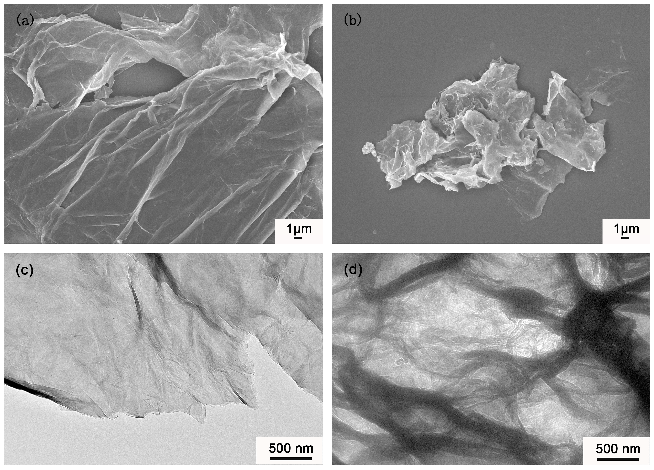
3.4. Morphology Analysis

Scanning electron microscopy and transmission electron microscopy were used to observe the morphologies of GO and ETEO-GO in Figure 6 and Figure S1. GO exhibited a lamellar structure in Figure 6a, and a stacking phenomenon occurred between the lamellas. The ETEO-GO sample (Figure 6b) exhibited a very rough surface, as well as a fluffy, homogeneous deposited, and folded morphology. The reason might be that the GO had high surface energy, resulting in high mutual attraction between lamellas. After modification by ETEO, the surface energy of ETEO-GO was reduced due to the presence of siloxane groups, resulting in a decrease of mutual attraction between the ETEO-GO lamellas and preventing the lamellas from being separated due to excessive interaction force. As can be seen from Figure 6c, GO has a typical lamella-like structure, and the surface is very wrinkled. In Figure 6d, the surface of ETEO-GO nanomaterials was very rough and did not appear in a simple lamella form. Combined with the conclusions drawn from FTIR, XRD and XPS, the ETEO-GO nanomaterial was successfully prepared.

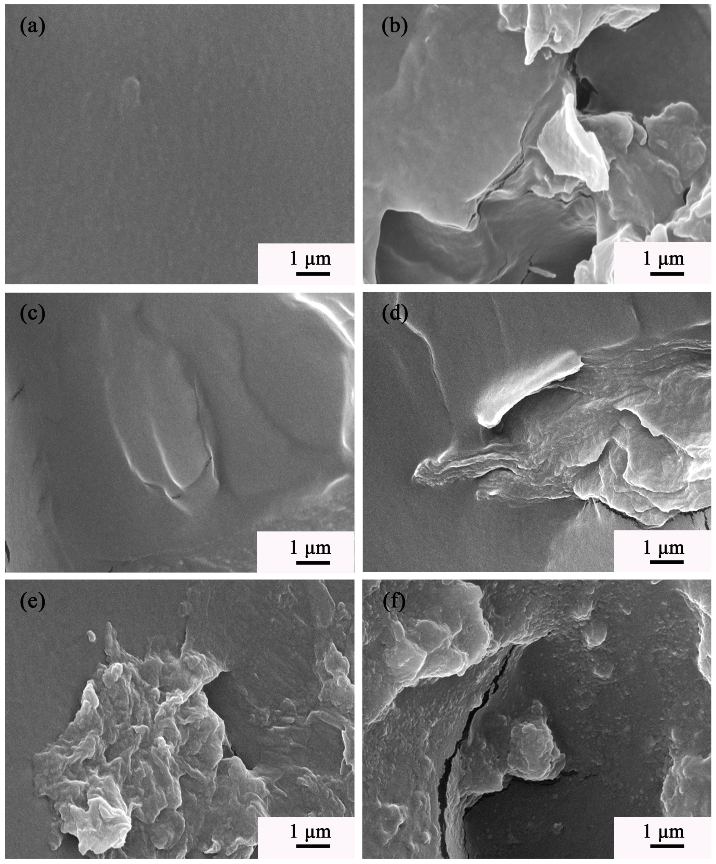
3.5. Morphology Analysis of Coating Cross-Section

The cross-section SEM image of the coating is shown in Figure 7 and Figure S2. Figure 7a shows the cross-sectional morphology of the EP coating. The cross-section of EP was very uniform and smooth with no other impurities. Figure 7b shows the cross-sectional SEM image of the GO coating. The GO had agglomeration in the coating, leading to a decrease in the compactness of the coating. Therefore, many cracks and holes appeared in the cross-section. The distribution of ETEO-GO in the two coatings (Figure 7c,d) did not agglomerate, and the fracture mode of the coating section was still dominated by brittle fracture. When the content of ETEO-GO was increased to 0.7 wt % (Figure 7e), the cross-sectional morphology of the coating changed from smooth to rough, and the presence of ETEO-GO was fluffy, helping the ETEO-GO fill in the epoxy coating and increasing the compactness of the coating. In Figure 7f, the amount of ETEO-GO added was increased to 1 wt %, and cracks and holes appeared in the cross section of the coating. The ETEO-GO was agglomerated, showing that the high content of ETEO-GO would decrease the compactness of the coating.

3.6. Mechanical Properties

Table 2 shows the results of the coating hardness tests. After the addition of GO, the hardness of the GO coating increased from 2H to 3H, while the hardness of the EGO3 coating with the same mass fraction increased by two grades. This result was mainly because the GO agglomerated in the coating and decreased the hardness due to the interaction force between the lamellas. With the increase of the amount of ETEO-GO added, the hardness of the coatings was continuously enhanced. When the addition amount was increased to 0.7 wt %, the hardness of the coating reached a maximum of 4H and did not continue to increase as the ETEO-GO continued to increase. This result may be attributed to the fact that ETEO-GO, as a rigid nanomaterial, can be evenly distributed in the epoxy resin to enhance the hardness of the coating. When ETEO-GO was added in excess to cause agglomeration, it still acted as a filler to enhance the strength of the coating and ensure that the coating retains its original strength.
Table 3 lists the results of the coating impact resistance tests. As shown in Table 3, when GO and ETEO-GO were added as fillers to the coatings, the impact resistance of the coatings was higher than that of the EP coating. It showed that the addition of fillers can improve the coating impact resistance. When the addition amount was 0.7 wt %, the impact resistance of the ETEO-GO coating was greatly improved, more so than that of GO coating. The reason might be that ETEO-GO had good dispersibility in epoxy resin. In addition, ETEO-GO can be arranged in parallel in the matrix resin, and the oxygen-containing groups on the surface can be crosslinked with epoxy resin. These can increase the uniformity of the coating. Also, the good dispersion of ETEO-GO in the epoxy resin matrix effectively filled the micropores and microcracks presented in the epoxy resin itself, thereby reducing the defects of the coatings. When the coatings were subjected to external impact, ETEO-GO would reduce the local stress concentration of the coatings due to the fewer amounts of defects and enhance the impact resistance of the coatings. When the addition amount of ETEO-GO was changed, the EGO3 coating showed the best impact resistance. As mentioned, ETEO-GO produced agglomeration in the EGO4 coating, causing cracks and holes in the coating, which resulted in the lower impact resistance of the EGO4 coating than EGO3.

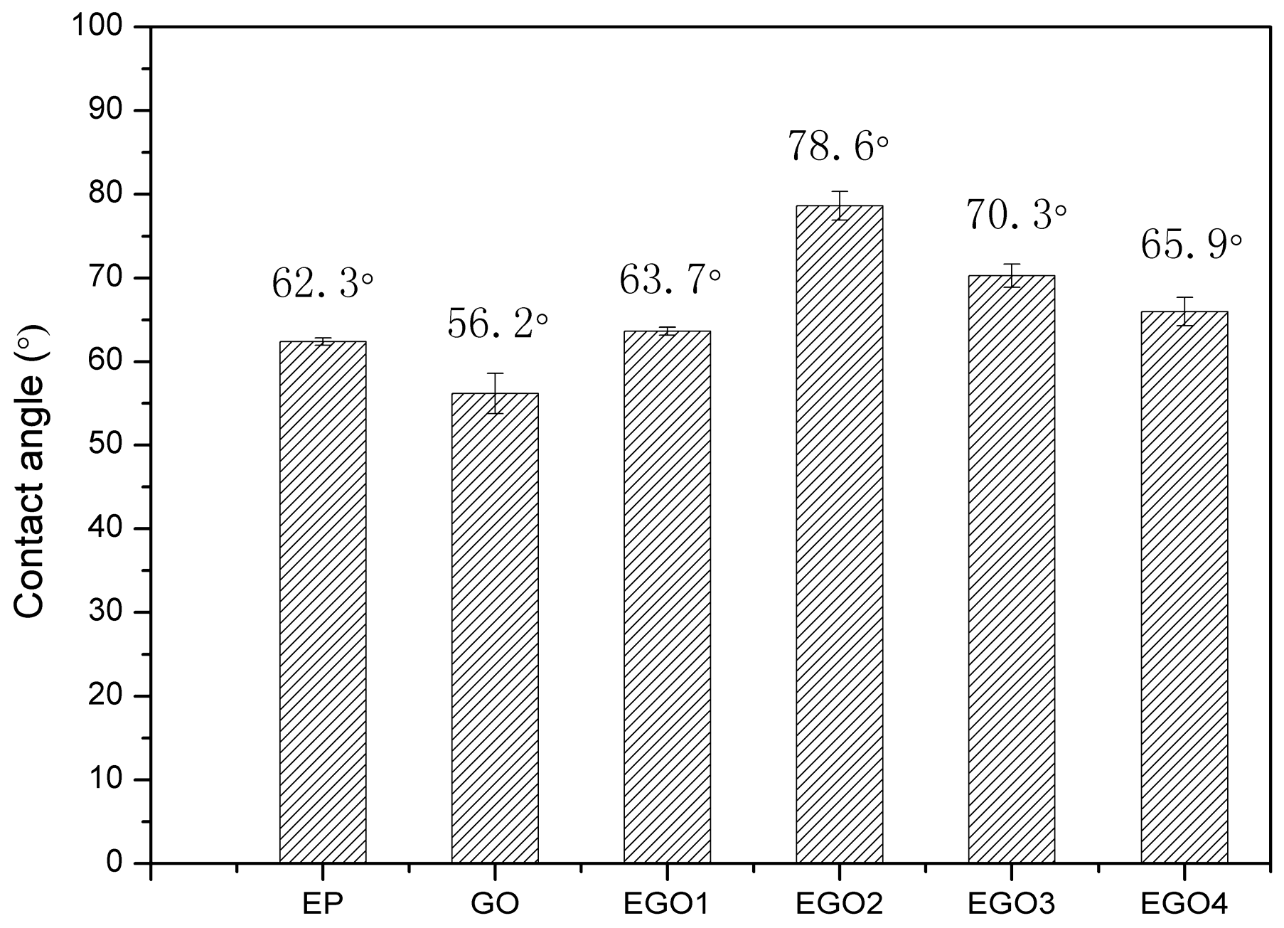
3.7. Wetting Performance

The contact angle can reflect the wettability of the coatings and affect the corrosion resistance [41]. Figure 8 shows a photograph of the contact angles of the composite coatings. The contact angle of the GO coating was reduced to 56.2° relative to the EP coating. This was mainly because the surface of the GO had a large number of oxygen-containing functional groups [42], and when the surface of the coating was in contact with water, the oxygen-containing functional groups were easily combined with water molecules by making hydrogen bonding [39], resulting in a phenomenon in which the value of the contact angle decreased. The ETEO molecule had a cyclohexene oxide group containing several methylene groups. Besides, Si–O–Si structure was formed after ETEO was grafted to the GO surface, which caused an increase in the non-polarity of the GO surface. Therefore, the surface energy of the ETEO-GO coating was lower than the GO coating, and the contact angle was higher as shown in Figure 8. In addition, due to the poor dispersion of GO, the surface energy of the coating may be uneven. The region where GO agglomerated was more likely to form hydrogen bonds. Thus, the contact angle was decreased and the surface energy was increased.

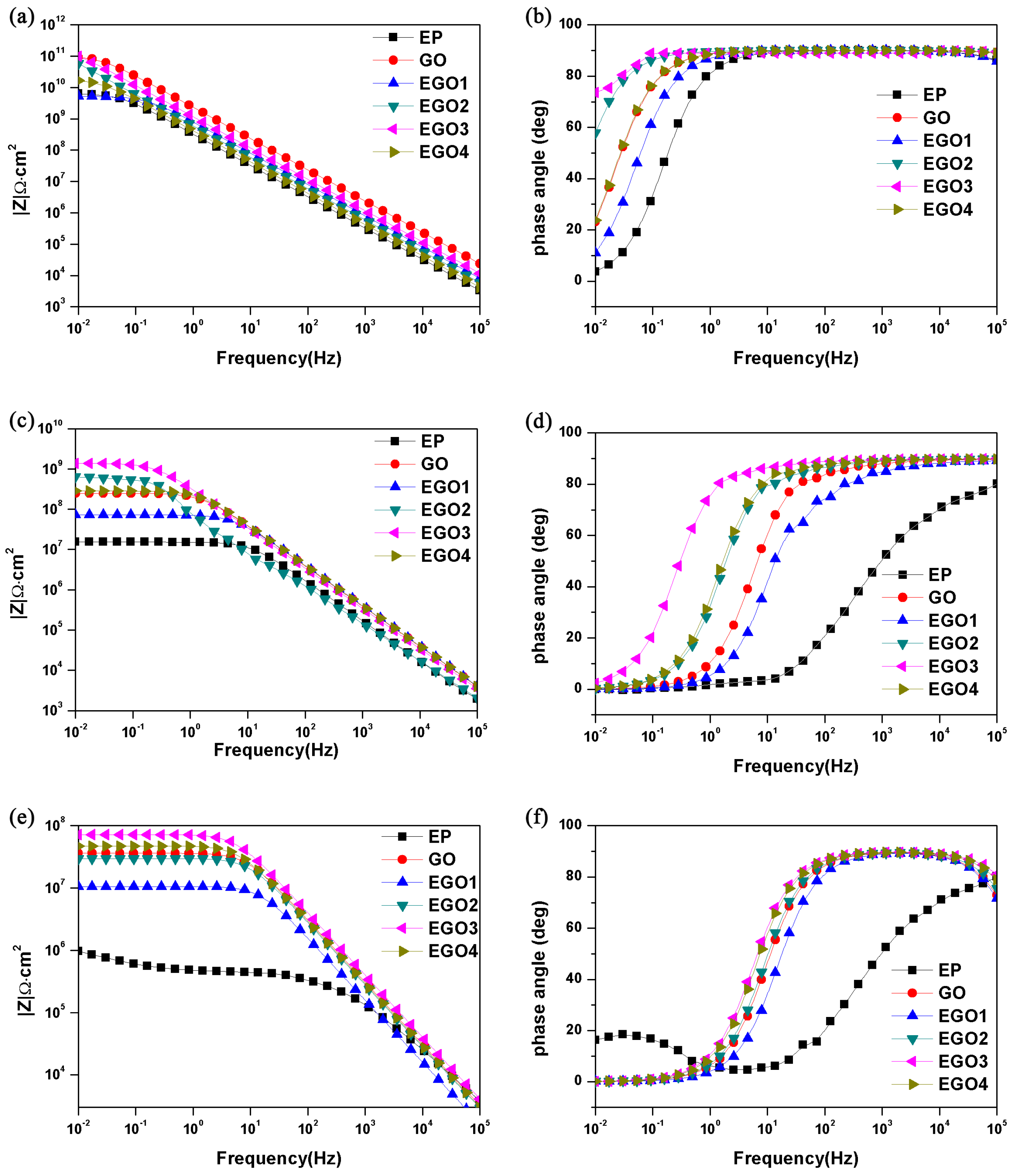
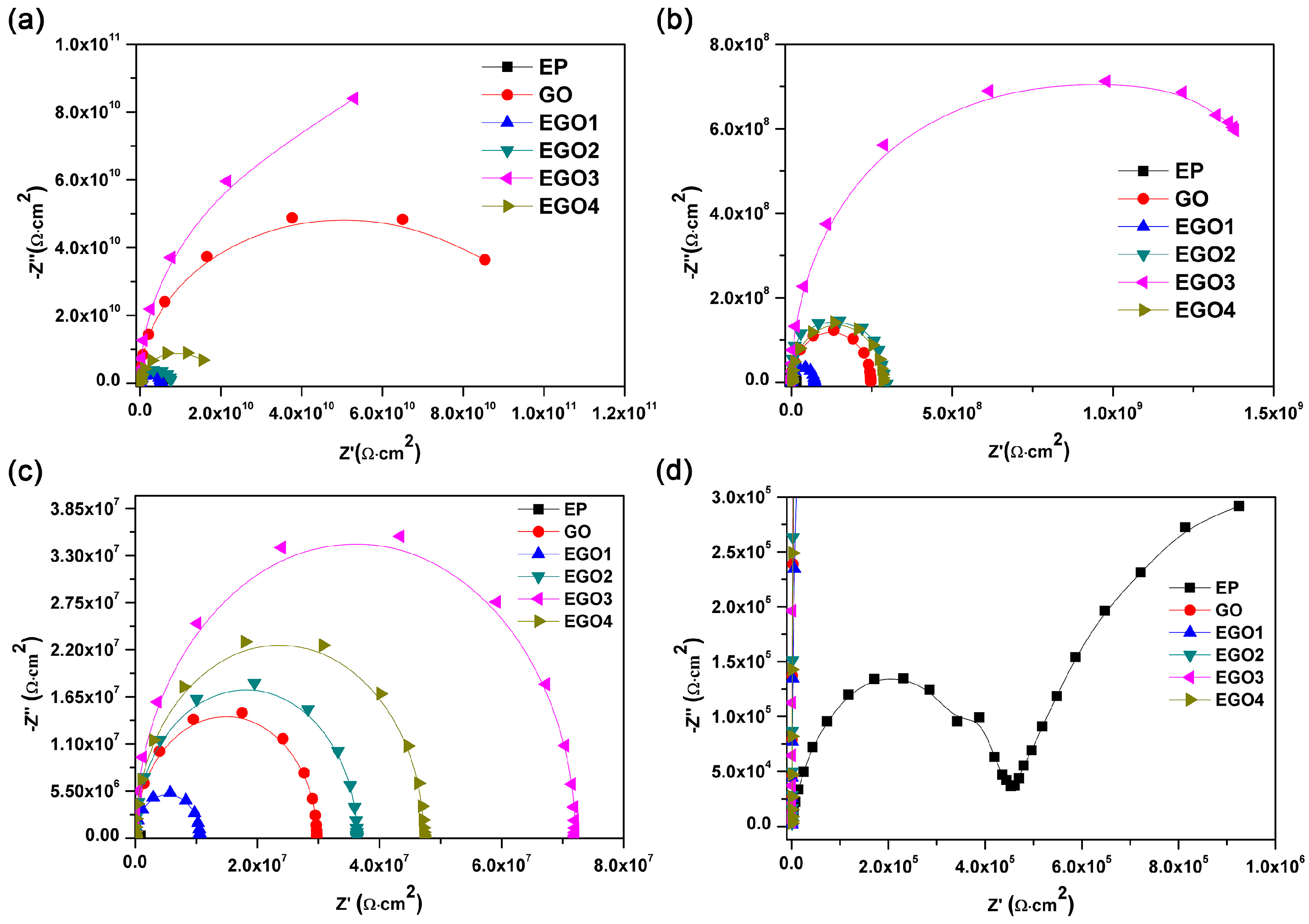
3.8. Electrochemical Impedance Spectroscopy

The coatings were immersed in a 3.5 wt % NaCl solution for 1 day, 10 days and 50 days. The electrochemical protection properties of the coating on the steel were observed, and the results are shown in Figure 9 and Figure 10. In Figure 9, the phase angle values of all coatings were close to 90° in the 10–105 Hz frequency range, and the low-frequency impedance modulus exceeded 109 Ω∙cm2, where the EGO3 coating was the highest in all samples, exceeding 1011 Ω∙cm2. After 10 days, the low-frequency impedance modulus of the EP coating and the GO coating were reduced to 2 × 10⁷ and 4 × 10⁸ Ω∙cm2, respectively, while the EGO3 coating remained above 109 Ω∙cm2. The phase angle of the EGO3 coating was close to 90° in the frequency range of 10–105 Hz. On the contrary, the phase angle value of the EP coating was obviously reduced, and the phase angle value of the GO coating in the intermediate frequency phase decreased rapidly. This result indicated that the defects caused by corrosion occurred in the two coatings at this time. The low-frequency impedance modulus of the EGO3 coating was still the highest among the all coatings after 50 days. Figure 10 shows the Nyquist diagrams of the coatings. The corrosion resistance of the coating can be measured by the radius of capacitance arc. After the immersion time reached 50 days, the EP coating was shown as two capacitance arcs with two relaxation times. The coating was contacted with the corrosive medium, and the corrosion protection effect failed. The curve radius of the EGO3 coating was always the largest in the Nyquist diagram of different immersed times, and the protection effect was the best. The data in the Bode and Nyquist diagrams shows that the corrosive medium passed through defects and holes of coating into coating/substrate interface, resulting in delamination of coating. The addition of GO filled in some coating defects. Given that the GO was not uniformly dispersed in the coating, the corrosion resistance was not greatly improved. The EGO3 coating still had good corrosion protection to the steel substrate after immersion for 50 days, which might be attributed to the organic functional groups on the surface of ETEO-GO that promoted its uniform dispersion in the coating to fill the holes and corrosion channels. The corrosion resistance of composite coatings for different levels of ETEO-GO can also be illustrated by the low-frequency impedance modulus. With the increase of ETEO-GO content, the corrosion resistance of EGO composite coatings first increased and then decreased, which may be caused by the agglomeration of ETEO-GO in the coating.

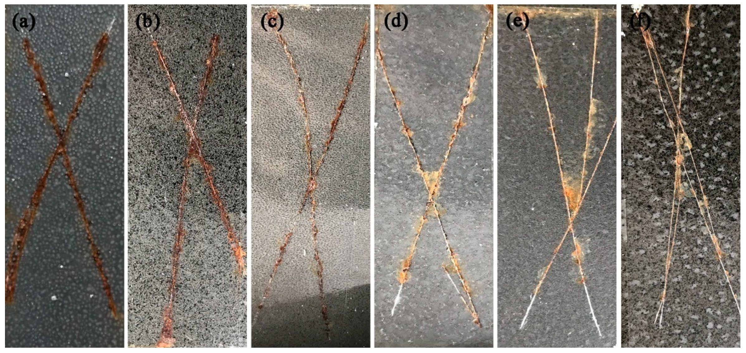
3.9. Salt Spray Test

Figure 11 is a digital photograph of coatings after a 400-h salt spray test. Rusts appeared on the surface of the EP coating, and a large area of blisters was generated on the surface, indicating that the corrosion medium had penetrated the EP coating completely to the steel substrate. However, a significant agglomeration of GO was observed in the GO coating, mainly because the uneven dispersion of GO in the coating resulted in different densities on the surface of the GO coating. The agglomeration of GO increased the number of micropores and microcracks in the coating. Micropores and microcracks can promote the generation of corrosion channels. Thus, a large amount of corrosive medium diffused through the corrosion channels to the substrate, then the substrate began to corrode, and corrosion products appeared. The corrosion products would destroy the original structure of the coating and enlarge the corrosion channels, which would eventually lead to more serious corrosion. Lowered corrosion products were created in the scratch section of the coatings reinforced by ETEO-GO. These results confirmed that surface modification of GO with ETEO improved the barrier and protection performance of the coatings. Besides, corrosion decreased with increasing ETEO-GO contents. The surface of the EGO3 and EGO4 coatings showed only a small amount of corrosion products and no blisters, showing better corrosion protection effects.

3.10. Analysis of Corrosion Protection Mechanism

The results of EIS experiments and salt spray tests showed that the corrosion resistance of the composite coatings was obviously improved after the addition of GO and ETEO-GO. The reason might be the reduction of cracks and micropores in the coating after the addition of GO and ETEO-GO. It has been shown that the addition of ETEO modified the GO surface and can significantly increase the layer spacing of GO or completely exfoliate away the lamellae. Therefore, the ETEO-GO was better dispersed in the coating system. During the curing process, ETEO-GO molecules with epoxide groups formed covalent bonds with the amino groups in the low molecular polyamide curing agents, which can enhance the crosslink density of the composite coating and increase the compatibility of the fillers with the coating matrix. Thereby, the barrier of the fillers can be increased against the penetration of the corrosive medium. Moreover, the cyclohexene oxide groups which existed in the ETEO molecules and Si–O–Si structures which formed after the modification can increase in the non-polarity of the GO surface and lower the surface energy of the ETEO-GO coatings.

5. Conclusions

ETEO silane coupling agent was synthesized by VCHO and TES through the hydrosilylation method, and the surface modification of GO was carried out by using ETEO. The periodic lamella structure of GO was grafted with ETEO and then destroyed and transformed into a fluffy state with a rough surface, which prevented the agglomeration of GO. The addition of ETEO-GO improved the mechanical properties of the coatings and imparted a certain hydrophobicity to the coatings. The results of EIS and salt spray tests showed that the coatings containing ETEO-GO had better corrosion resistance than the pure epoxy coating and the coatings with GO. The coating with 0.7 wt % ETEO-GO showed the most excellent corrosion resistance.

Supplementary Materials

The following are available online at https://www.mdpi.com/2079-6412/9/1/46/s1, Figure S1: TEM images of (a) GO and (b) ETEO-GO, Figure S2: SEM images of cross-section microstructures for smaller magnifications: (a) EP; (b) GO; (c) EGO1; (d) EGO2; (e) EGO3; and (f) EGO4.

Author Contributions

Conceptualization, C.Z., Y.D. and X.D.; Formal Analysis, C.Z., X.D. and G.S.; Data Curation, X.D., Y.W. and L.Q.; Writing—Original Draft Preparation, X.D. and Y.W.; Writing—Review and Editing, X.D., Y.S. and P.L.

Funding

This research was funded by the Jilin Province Natural Science Foundation of China (No. 20180101197jc).

Conflicts of Interest

The authors declare no conflict of interest.

References

  1. Zheludkevich, M.L.; Tedim, J.; Ferreira, M.G.S. “Smart” coatings for active corrosion protection based on multi-functional micro and nanocontainers. Electrochim. Acta 2012, 82, 314–323. [Google Scholar] [CrossRef]
  2. Tallman, D.E.; Spinks, G.; Dominis, A.; Wallace, G.G. Electroactive conducting polymers for corrosion control. J. Solid State Electrochem. 2002, 6, 73–84. [Google Scholar] [CrossRef]
  3. Nguyen, T.N.; Hubbard, J.B.; McFadden, G.B. Mathematical model for the cathodic blistering of organic coatings on steel immersed in electrolytes. J. Coat. Technol. 1991, 63, 43–52. [Google Scholar]
  4. Grundmeier, G.; Schmidt, W.; Stratmann, M. Corrosion protection by organic coatings: Electrochemical mechanism and novel methods of investigation. Electrochim. Acta 2000, 45, 2515–2533. [Google Scholar] [CrossRef]
  5. Babić, R.; Metikoš-Huković, M.; Radovčić, H. The study of coal tar epoxy protective coatings by impedance spectroscopy. Prog. Org. Coat. 1994, 23, 275–286. [Google Scholar] [CrossRef]
  6. Pascault, J.P.; Williams, R.J.J. Relationships between glass-transition temperature and conversion-analyses of limiting cases. Polym. Bull. 1990, 24, 115–121. [Google Scholar] [CrossRef]
  7. Chmielewska, D.; Sterzyński, T.; Dudziec, B. Epoxy compositions cured with aluminosilsesquioxanes: Thermomechanical properties. J. Appl. Polym. Sci. 2014, 131, 8444–8452. [Google Scholar] [CrossRef]
  8. Arman, S.Y.; Ramezanzadeh, B.; Farghadani, S.; Mehdipour, M.; Rajabi, A. Application of the electrochemical noise to investigate the corrosion resistance of an epoxy zinc-rich coating loaded with lamellar aluminum and micaceous iron oxide particles. Corros. Sci. 2013, 77, 118–127. [Google Scholar] [CrossRef]
  9. Gharagozlou, M.; Ramezanzadeh, B.; Baradaran, Z. Synthesize and characterization of a novel anticorrosive cobalt ferrite nanoparticles dispersed in silica matrix (CoFe2O4-SiO2) to improve the corrosion protection performance of epoxy coating. Appl. Surf. Sci. 2016, 377, 86–98. [Google Scholar] [CrossRef]
  10. Shanker, A.K.; Cervantes, C.; Loza-Tavera, H.; Avudainayagam, S. Chromium toxicity in plants. Environ. Int. 2005, 31, 739–753. [Google Scholar] [CrossRef]
  11. Hodgkin, J.H.; Simon, G.P.; Varley, R.J. Thermoplastic toughening of epoxy resins: A critical review. Polym. Adv. Technol. 1998, 9, 3–10. [Google Scholar] [CrossRef]
  12. Na, T.; Liu, X.; Jiang, H.; Zhao, L.; Zhao, C. Enhanced thermal conductivity of fluorinated epoxy resins by incorporating inorganic filler. React. Funct. Polym. 2018, 128, 84–90. [Google Scholar] [CrossRef]
  13. Tao, Z.; Yang, S.; Ge, Z.; Chen, J.; Fan, L. Synthesis and properties of novel fluorinated epoxy resins based on 1,1-bis(4-glycidylesterphenyl)-1-(3′-trifluoromethylphenyl)-2,2,2-trifluoroethane. Eur. Polym. J. 2007, 43, 550–560. [Google Scholar] [CrossRef]
  14. Chikhi, N.; Fellahi, S.; Bakar, M. Modification of epoxy resin using reactive liquid (ATBN) rubber. Eur. Polym. J. 2002, 38, 251–264. [Google Scholar] [CrossRef]
  15. Chaudhary, S.; Surekha, P.; Kumar, D.; Rajagopal, C.; Roy, P.K. Amine-functionalized poly(styrene) microspheres as thermoplastic toughener for epoxy resin. Polym. Compos. 2015, 36, 174–183. [Google Scholar] [CrossRef]
  16. Conde, A.; Durán, A.; de Damborenea, J.J. Polymeric sol–gel coatings as protective layers of aluminium alloys. Prog. Org. Coat. 2003, 46, 288–296. [Google Scholar] [CrossRef] [Green Version]
  17. Dhoke, S.K.; Khanna, A.S. Effect of nano-Fe2O3 particles on the corrosion behavior of alkyd based waterborne coatings. Corros. Sci. 2009, 51, 6–20. [Google Scholar] [CrossRef]
  18. Dolatzadeh, F.; Moradian, S.; Jalili, M.M. Influence of various surface treated silica nanoparticles on the electrochemical properties of SiO2/polyurethane nanocoatings. Corros. Sci. 2011, 53, 4248–4257. [Google Scholar] [CrossRef]
  19. Kozhukharov, S.; Tsaneva, G.; Kozhukharov, V.; Gerwann, J.; Schem, M.; Schmidt, T.; Veith, M. Corrosion protection properties of composite hybrid coatings with involved nanoparticles of zirconia and ceria. J. Univ. Chem. Technol. Metall. 2008, 43, 73–80. [Google Scholar]
  20. Radhakrishnan, S.; Siju, C.R.; Mahanta, D.; Patil, S.; Madras, G. Conducting polyaniline–nano-TiO2 composites for smart corrosion resistant coatings. Electrochim. Acta 2009, 54, 1249–1254. [Google Scholar] [CrossRef]
  21. Ramezanzadeh, B.; Attar, M.M. Studying the corrosion resistance and hydrolytic degradation of an epoxy coating containing zno nanoparticles. Mater. Chem. Phys. 2011, 130, 1208–1219. [Google Scholar] [CrossRef]
  22. Schem, M.; Schmidt, T.; Gerwann, J.; Wittmar, M.; Veith, M.; Thompson, G.E.; Molchan, I.S.; Hashimoto, T.; Skeldon, P.; Phani, A.R.; et al. CeO2-filled sol–gel coatings for corrosion protection of AA2024-T3 aluminium alloy. Corros. Sci. 2009, 51, 2304–2315. [Google Scholar] [CrossRef]
  23. Yu, H.J.; Wang, L.; Shi, Q.; Jiang, G.H.; Zhao, Z.R.; Dong, X.C. Study on nano-CaCO3 modified epoxy powder coatings. Prog. Org. Coat. 2006, 55, 296–300. [Google Scholar] [CrossRef]
  24. Wan, Y.-J.; Tang, L.-C.; Gong, L.-X.; Yan, D.; Li, Y.-B.; Wu, L.-B.; Jiang, J.-X.; Lai, G.-Q. Grafting of epoxy chains onto graphene oxide for epoxy composites with improved mechanical and thermal properties. Carbon 2014, 69, 467–480. [Google Scholar] [CrossRef]
  25. Yi, H.; Chen, C.; Zhong, F.; Xu, Z. Preparation of aluminum oxide-coated carbon nanotubes and the properties of composite epoxy coatings research. High Perform. Polym. 2014, 26, 255–264. [Google Scholar] [CrossRef]
  26. Kalenda, P.; Kalendová, A.; Štengl, V.; Antoš, P.; Šubrt, J.; Kváča, Z.; Bakardjieva, S. Properties of surface-treated mica in anticorrosive coatings. Prog. Org. Coat. 2004, 49, 137–145. [Google Scholar] [CrossRef]
  27. Dong, Y.; Li, S.; Zhou, Q. Self-healing capability of inhibitor-encapsulating polyvinyl alcohol/polyvinylidene fluoride coaxial nanofibers loaded in epoxy resin coatings. Prog. Org. Coat. 2018, 120, 49–57. [Google Scholar] [CrossRef]
  28. Spainhour, L.K.; Wootton, I.A. Corrosion process and abatement in reinforced concrete wrapped by fiber reinforced polymer. Cem. Concr. Compos. 2008, 30, 535–543. [Google Scholar] [CrossRef]
  29. Shi, X.; Nguyen, T.A.; Suo, Z.; Liu, Y.; Avci, R. Effect of nanoparticles on the anticorrosion and mechanical properties of epoxy coating. Surf. Coat. Technol. 2009, 204, 237–245. [Google Scholar] [CrossRef]
  30. Stankovich, S.; Dikin, D.A.; Dommett, G.H.; Kohlhaas, K.M.; Zimney, E.J.; Stach, E.A.; Piner, R.D.; Nguyen, S.T.; Ruoff, R.S. Graphene-based composite materials. Nature 2006, 442, 282–286. [Google Scholar] [CrossRef]
  31. Liang, J.; H, Y.; Zhang, L.; Wang, Y.; Ma, Y.; Guo, T.; Chen, Y. Molecular-level dispersion of graphene into poly(vinyl alcohol) and effective reinforcement of their nanocomposites. Adv. Funct. Mater. 2009, 19, 2297–2302. [Google Scholar] [CrossRef]
  32. Dreyer, D.R.; Park, S.; Bielawski, C.W.; Ruoff, R.S. The chemistry of graphene oxide. Chem. Soc. Rev. 2010, 39, 228–240. [Google Scholar] [CrossRef] [PubMed]
  33. Li, Z.; Wang, R.; Young, R.J.; Deng, L.; Yang, F.; Hao, L.; Jiao, W.; Liu, W. Control of the functionality of graphene oxide for its application in epoxy nanocomposites. Polymer 2013, 54, 6437–6446. [Google Scholar] [CrossRef]
  34. Wang, Y.N.; Dai, X.Y.; Xu, T.L.; Qu, L.J.; Zhang, C.L. Preparation and anticorrosion properties of silane grafted nano-silica/epoxy composite coating. Chem. J. Chin. Univ. 2018, 39, 1564–1572. [Google Scholar]
  35. Hummers, W.S.; Offeman, R.E. Preparation of graphitic oxide. J. Am. Chem. Soc. 1958, 80, 1339. [Google Scholar] [CrossRef]
  36. GB/T 6739-2006 Paints and Varnishes–Determination of Film Hardness by Pencil Test; Standardization Administration of China: Beijing, China, 2006. (In Chinese)
  37. ASTM D2794-93 Standard Test Method for Resistance of Organic Coatings to the Effects of Rapid Deformation (Impact); ASTM International: West Conshohocken, PA, USA, 2010.
  38. GB/T 10125-1997 Corrosion Tests in Artificial Atmospheres–Salt Spray Tests; Standardization Administration of China: Beijing, China, 2006. (In Chinese)
  39. Ramezanzadeh, B.; Ahmadi, A.; Mahdavian, M. Enhancement of the corrosion protection performance and cathodic delamination resistance of epoxy coating through treatment of steel substrate by a novel nanometric sol-gel based silane composite film filled with functionalized graphene oxide nanosheets. Corros. Sci. 2016, 109, 182–205. [Google Scholar] [CrossRef]
  40. Ganjaee Sari, M.; Shamshiri, M.; Ramezanzadeh, B. Fabricating an epoxy composite coating with enhanced corrosion resistance through impregnation of functionalized graphene oxide-co-montmorillonite nanoplatelet. Corros. Sci. 2017, 129, 38–53. [Google Scholar] [CrossRef]
  41. Zhang, D.; Wang, L.; Qian, H.; Li, X. Superhydrophobic surfaces for corrosion protection: A review of recent progresses and future directions. J. Coat. Technol. Res. 2016, 13, 11–29. [Google Scholar] [CrossRef]
  42. Kang, W.-S.; Rhee, K.Y.; Park, S.-J. Influence of surface energetics of graphene oxide on fracture toughness of epoxy nanocomposites. Compos. Part B Eng. 2017, 114, 175–183. [Google Scholar] [CrossRef]
Figure 1. Schematic reaction of the 4-vinyl-1-cyclohexene-1,2-epoxide (VCHO) and triethoxysilane (TES).
Coatings 09 00046 g001
Figure 2. Synthesis reaction of GO and 2-(3,4-epoxycyclohexyl)ethyl triethoxysilane (ETEO).
Coatings 09 00046 g002
Figure 3. Fourier transform infrared spectroscopy (FTIR) spectroscopy of GO and ETEO-GO.
Coatings 09 00046 g003
Figure 4. XRD pattern spectra of GO and ETEO-GO.
Coatings 09 00046 g004
Figure 5. XPS survey spectra: (a) GO, (c) ETEO-GO; and high resolution spectra: (b) C 1s of GO, (d) C 1s of ETEO-GO.
Coatings 09 00046 g005
Figure 6. Morphologies of GO and ETEO-GO: (a) SEM image of GO; (b) SEM image of ETEO-GO; (c) TEM images of GO; (d) TEM images of ETEO-GO.
Coatings 09 00046 g006
Figure 7. SEM images of cross-section microstructures: (a) EP; (b) GO; (c) EGO1; (d) EGO2; (e) EGO3; and (f) EGO4.
Coatings 09 00046 g007
Figure 8. Water contact angle test results of different coatings: EP, GO, EGO1, EGO2, EGO3, and EGO4.
Coatings 09 00046 g008
Figure 9. Bode diagrams of coatings immersed in 3.5 wt % NaCl solution for (a,b) 1 day; (c,d) 10 days and (e,f) 50 days.
Coatings 09 00046 g009
Figure 10. Nyquist diagrams of coatings immersed in 3.5 wt % NaCl solution for (a) 1 day, (b) 10 days and (c) 50 days. (d) Enlarged view of the red area in (c).
Coatings 09 00046 g010
Figure 11. Photograph of samples after salt spray test for 400 h: (a) EP; (b) GO; (c) EGO1; (d) EGO2; (e) EGO3; and (f) EGO4.
Coatings 09 00046 g011
Table 1. Formation of coatings.
SampleEpoxy Resin (g)Curing Agent (g)Filler (wt %)
Pure epoxy (EP)2016
GO2016GO (0.7 wt %)
EGO12016ETEO-GO (0.1 wt %)
EGO22016ETEO-GO (0.4 wt %)
EGO32016ETEO-GO (0.7 wt %)
EGO42016ETEO-GO (1.0 wt %)
Table 2. Hardness of EP, GO, and EGO coatings.
SampleHardness (H)
EP2
GO3
EGO12
EGO23
EGO34
EGO44
Table 3. Impact resistance of EP, GO, and EGO coatings; the values are the mean of five replicates and (±) correspond to the standard.
SampleHeight (cm)
EP10.2 ± 0.5
GO38.7 ± 1.6
EGO119.4 ± 0.4
EGO222.4 ± 0.5
EGO3≥50
EGO440.1 ± 0.9

