Short Note

An Analysis of Effect of CO2 Laser Treatment on Carbon Fibre Fabric

1
Department of Materials Science and Engineering, Feng Chia University, No. 100 Wenhwa Rd., Seatwen, Taichung 40724, Taiwan
2
Institute of Textiles and Clothing, The Hong Kong Polytechnic University, Hung Hom, Kowloon, Hong Kong, China
*
Author to whom correspondence should be addressed.
Coatings 2018, 8(5), 178; https://doi.org/10.3390/coatings8050178
Submission received: 14 March 2018 / Revised: 30 April 2018 / Accepted: 2 May 2018 / Published: 6 May 2018
(This article belongs to the Special Issue Laser Surface Treatment)

Abstract

:
The colour of carbon fibre fabric is black which limits its aesthetic properties. CO2 laser has been used for cutting carbon fibres. The impact of CO2 laser treatment to modify the surface of carbon fibre fabric is investigated in this work. Different combinations of laser process parameters, i.e., pixel time (110, 120, 130, 140, 150, 160, 170, 180, 190 and 200 µs, with 10 µs intervals) and resolution (70, 80, 90 and 100 dpi (dots per inch), with 10 dpi intervals), were used for treating carbon fibre fabric surface. Since the laser process is a surface treatment, contact angle measurement was used for evaluating the wetting property imparted after laser processing. The resistivity of the laser-treated carbon fibre fabric was measured to evaluate any effect on the original electrical property of the carbon fibre fabric. Moreover, surface morphology and functionality of laser-treated carbon fibre fabric were assessed by scanning electron microscopy (SEM) and Fourier transform infrared spectroscopy-attenuated total internal reflectance (FTIR-ATR), respectively. SEM assessment was to examine the physical change in the carbon fibre surface after laser processing. On the other hand, the FTIR-ATR measurement can help to evaluate the chemical change in the carbon fibre surface after laser processing.

1. Introduction

Carbon fibre fabric generally contains at least 92 wt % of carbon [1,2]. This high carbon content can make it have good mechanical properties, thermal resistance, chemical inertness and electrical conductivity [1,3]. Thus, carbon fibre fabric is a very good material for different applications such as sports equipment and military purposes [3,4,5,6]. However, the colour of carbon fibre fabric is black which limits its aesthetic properties [7]. Therefore, this study attempts to identify a physical method to improve aesthetic properties of carbon fibre fabric. Among different physical methods, CO2 laser treatment is an effective physical surface treatment used for different types of fabrics. Due to the increasing concerns on environmental protection issue, CO2 laser treatment is a method for surface treatment which is based purely on physical interaction between the laser and the material surface [8,9,10,11,12]. Previous studies reveal that CO2 laser treatment is a good candidate for changing aesthetic properties of materials in fabric form [13,14,15]. With careful control of CO2 laser treatment process parameters, the aesthetic effects (surface textual effects) can be controlled with minimum damage of the material itself [16,17,18,19,20]. Therefore, the aim of this study was to evaluate the impact of CO2 laser treatment on carbon fibre fabric. It is expected that CO2 laser treatment can provide an effective way to enhance the surface textual effect (aesthetic effect) of carbon fibre fabric without altering its original properties.

2. Experimental

2.1. Materials

Carbon fibre fabric (without sizing material) in woven form (99.5% carbon, 30 picks per inch and 30 ends per inch) (model: 1071 HCB, manufactured by AvCarb, supplied by Fuel Cell Store, Lowell, TX, USA) was used in this study. The fabric weight and thickness were 132 g/m2 and 0.356 mm, respectively. The carbon fibre fabric was first cleaned with acetone (30 mL/L) for 15 min to remove oily and greasy impurities on the fabric surface. After cleaning, the fabric was dried completely in an oven at 70 °C for at least 15 min. The cleaned carbon fibre fabric was then stored in a conditioning room with relative humidity of 65% ± 2% at 21 ± 1 °C for at least 24 h before use.

2.2. Laser Treatment

Industrial scale laser engraving machine (with pulsed CO2 source, wavelength = 10.6 µm) (“Flexi-e V2”, Jeanologia, Valencia, Spain) coupled to a laser operating system “eMark” was used in the study in normal atmospheric environment. The carbon fibre fabric samples were laid flat on the laser treatment table to avoid wrinkling effect and uneven laser irradiation. The carbon fibre fabrics were then treated under different combinations (total 40 combinations) of laser process parameters, i.e., pixel time (110, 120, 130, 140, 150, 160, 170, 180, 190 and 200 µs, with 10 µs intervals) and resolution (70, 80, 90 and 100 dpi (dots per inch), with 10 dpi intervals). The laser fluence was in the range of 3.50–70.0 W/cm2. The surface engraved pattern size in the carbon fibre fabric was 5 cm × 5 cm. After laser treatment, the samples were conditioned with relative humidity of 65% ± 2% and 21 ± 1 °C for at least 24 h before evaluation.

2.3. Contact Angle Measurement

The surface wetting behaviour of the carbon fibre fabric was measured using a contact angle meter (CAM-Micro, Tantec, IL, USA) [19]. A drop of 5 μL deionised water was used to probe the sample surface. The image of the water droplet was captured by a high-resolution camera and the water contact angle was measured from the image. Several readings were measured for each sample and three readings with 95% confidence level were taken and the mean value was calculated.

2.4. Electrical Resistance Measurement

A multimeter (model 280, KITLER, Istanbul, Turkey) was used to measure electrical resistance of carbon fibre fabric. The range of measurement was selected at 20 Ω (resolution at 0.01 Ω). The multimeter was connected to two copper electrodes. Each of the electrodes had a contact area 1 cm × 3 cm against sample. Long edge of the two electrodes was in parallel and at 3 cm distance with each other. During resistance measurement, carbon fibre fabric was placed on a flat and insulated surface. Then, the electrodes were pressed against sample surface with 3 kgf (each) to ensure good contact. The resistance measurements were conducted in both warp and weft directions. Several readings were measured for each sample and three readings with 95% confidence level were taken and the mean value was calculated.

2.5. Scanning Electron Microscopy (SEM)

Surface morphology of the fabric was investigated by SEM (Model JSM-6490, JEOL, Tokyo, Japan) with a resolution up to 15,000×.

2.6. Fourier Transform Infrared Spectroscopy-Attenuated Total Internal Reflectance (FTIR-ATR)

The surface functional groups of laser-treated carbon fibre fabric were determined by a Fourier Transform infrared spectrophotometer (Spectrum 100, Perkin Elmer Limited, Waltham, MA, USA) equipped for measuring attenuated total internal reflectance (ATR). FTIR-ATR spectrum of the carbon fibre surface was obtained with 64 scans at 4 cm−1 resolution.

3. Results and Discussion

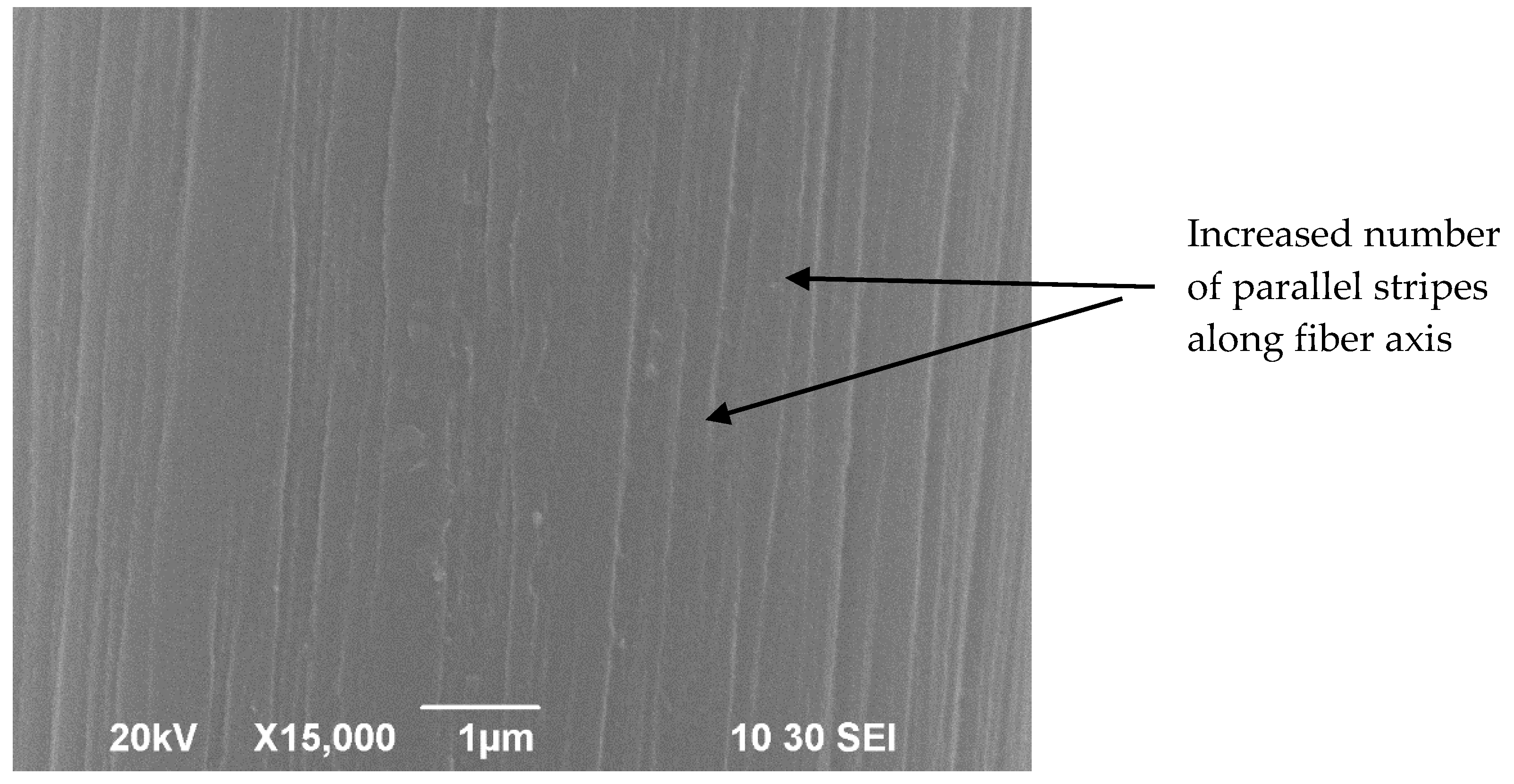
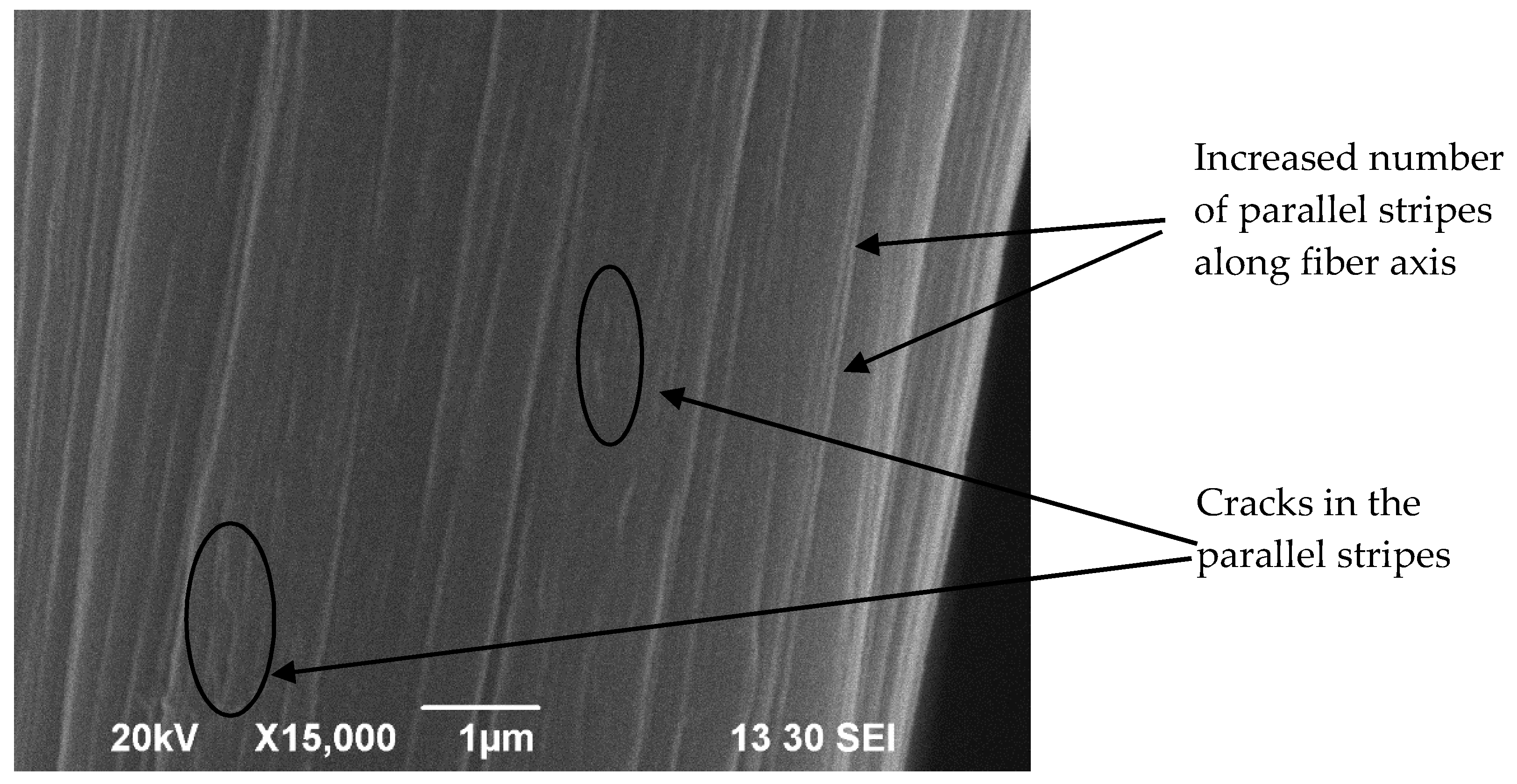
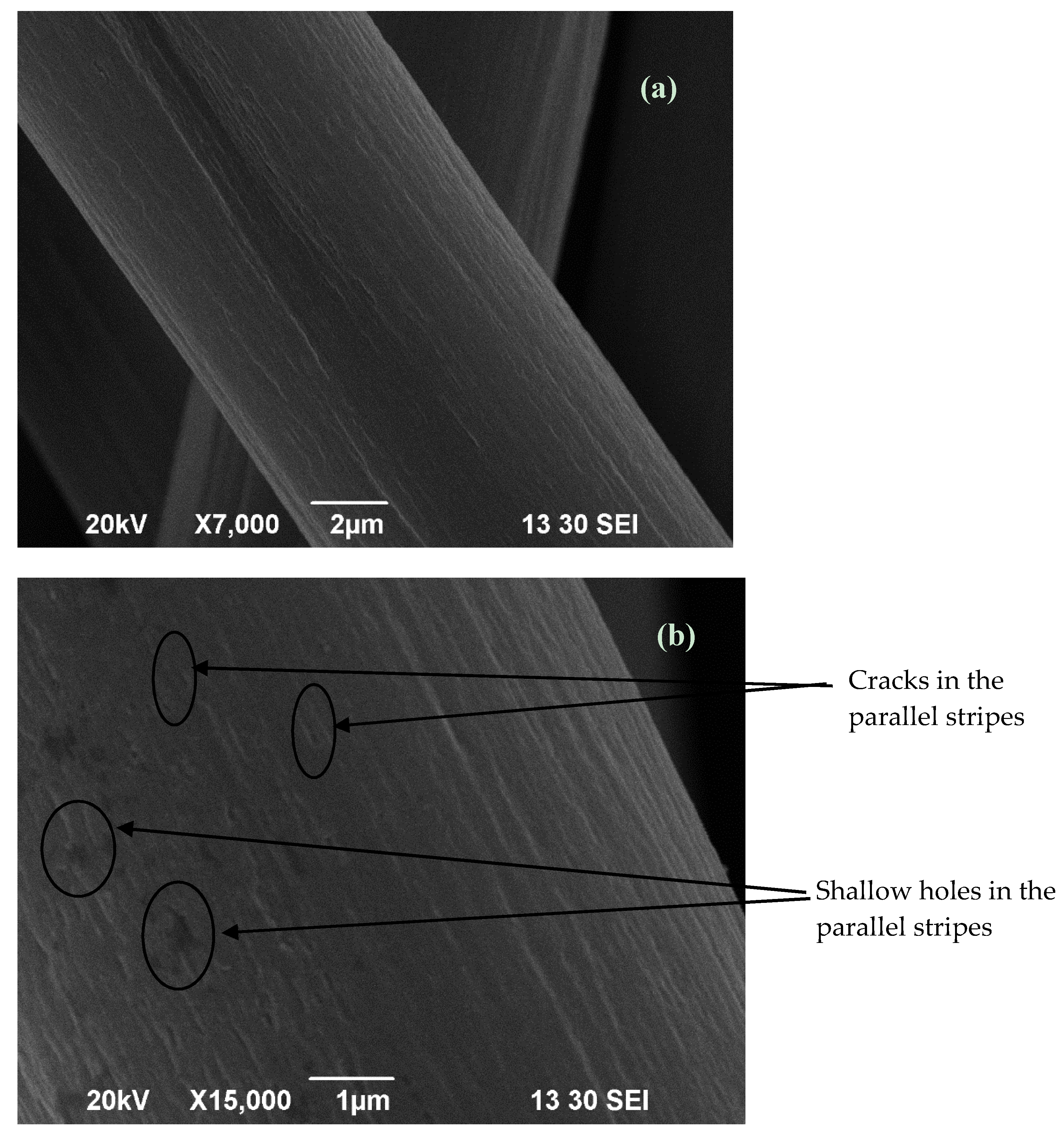
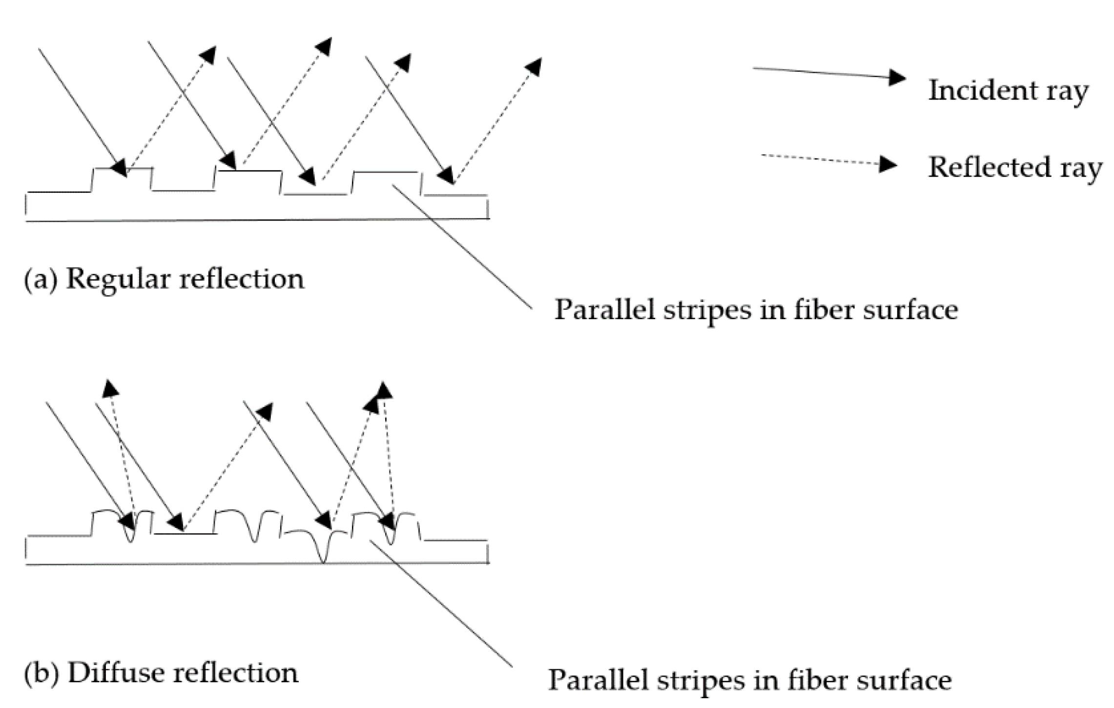
3.1. Surface Morphology

Figure 1 shows the image of carbon fibre fabric laser-engraved with different combinations of laser process parameters, i.e., pixel time (110, 120, 130, 140, 150, 160, 170, 180, 190 and 200 µs) and resolution (70, 80, 90 and 100 dpi). Obviously, the laser treatment can introduce pattern and design effect on the carbon fibre fabric. Since carbon fibre fabric is very difficult to be coloured, the pattern and design effect can enhance aesthetic properties of the fabric. With the use of laser processing, there is no significant change in electrical resistance of the laser-treated carbon fibre fabric. Thus, laser treatment is a good process to enhance aesthetic properties of carbon fibre fabric without altering its original electrical properties [21,22,23]. Based on the pattern in Figure 1, it is noted that the pattern intensity becomes darker with increasing pixel time and resolution. The pattern with the highest darkness intensity is 200 µs/100 dpi which may be due to the highest laser energy applied.
Figure 2, Figure 3, Figure 4, Figure 5 and Figure 6 illustrate image of the surface of different carbon fibre fabrics. Figure 2 shows the SEM image of untreated carbon fibre fabric and Figure 3, Figure 4, Figure 5 and Figure 6 show different laser-treated carbon fibre fabrics.
Figure 3, Figure 4, Figure 5 and Figure 6 show that carbon fibre fabrics treated with different combinations of laser parameters show different surface appearances. The common surface feature of laser-treated fabrics is that the parallel stripes along the fibre axis remain unaffected, but the density of parallel stripes increases after laser treatment. In laser treatment, the laser may interact with the carbon fibre fabric surface and influence surface appearance.
Figure 3 and Figure 4 show carbon fibre fabrics treated with the same pixel time (110 µs) (the laser irradiation time) but different resolutions (70 and 100 dpi). If high resolution is used, laser density per inch increases, which means more surface area is covered by the laser beam. In the case of Figure 3 and Figure 4, it is obvious that laser irradiation increases the number of parallel stripes in the carbon fibre fabric. With resolution of 100 dpi, some shallow cracks are observed in the parallel stripes. This effect may be due to the increase in laser energy density per area when resolution is increased from 70 to 100 dpi.
Figure 3 and Figure 5 depict specimens treated with the same resolution of 70 dpi but with different pixel times. Density of parallel stripes is similar in both but some deep cracks are noted in the case of longer pixel time (Figure 5). This is due to the long pixel time allowing more time for a laser beam to irradiate at the same location, leading to the deep crack formation.
Figure 4 and Figure 6 show a trend similar to Figure 3 and Figure 5. With pixel time increasing from 110 to 200 µs, the surface effect is enhanced, i.e., intensity of parallel stripes along the fibre axis and cracks formed in the parallel stripes are increased. In addition, some holes appear on the surface. Because of the use of highest pixel time in this study, the laser beam has the longest time to irradiate at one location and thus the cracks formed may have become deep holes because of the longer laser treatment time. Obviously, the CO2 laser treatment with resolution of 100 dpi and pixel time of 200 µs roughened the surface significantly when compared with other combinations of laser process parameters.
In Figure 6, it is clear that the surface modification is distributed uniformly in the carbon fibre surface as indicated at low magnification (7000×) (Figure 6a) and high magnification (15,000×) (Figure 6b).
SEM image in Figure 2 shows that the surface is smooth and even in the untreated carbon fibre fabric. Parallel stripes are noted along the fibre axis with uniform size. This uniform and smooth surface structure contributes to an even surface in the untreated carbon fibre fabric. When light is reflected from such even surface, regular reflection (Figure 7a) occurs and makes the carbon fibre fabric appear lighter than other portions with laser treatment (Figure 1). On the other hand, with laser treatment, the carbon fibre surface is etched and roughened. Thus, when light is reflected from such rough and uneven surface, diffuse reflection (Figure 7b) may occur and the lustrous property of the carbon fibre fabric is reduced. Therefore, the laser-treated carbon fibre looks darker than untreated carbon fibre as shown in Figure 1.

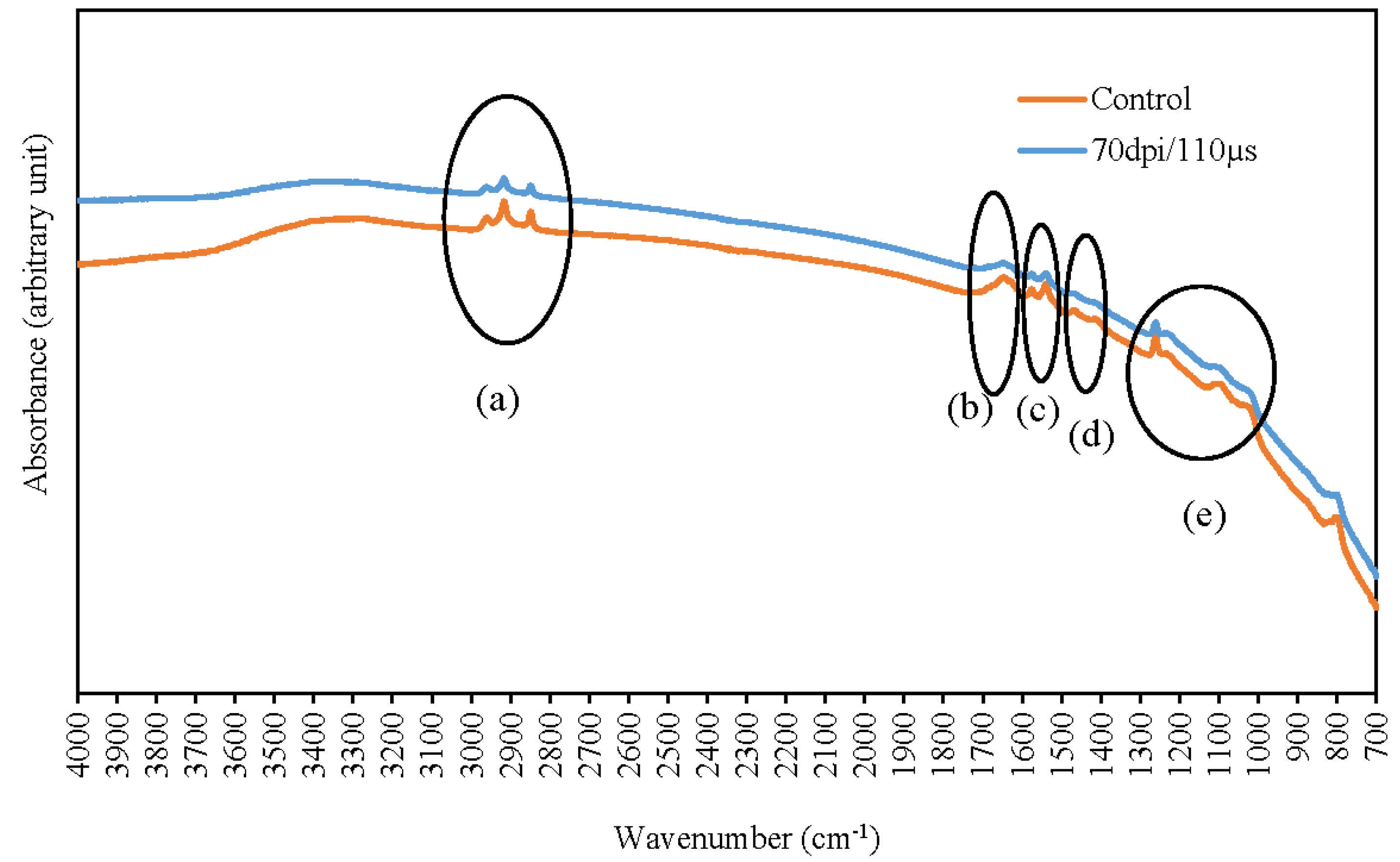
3.2. Surface Functional Groups
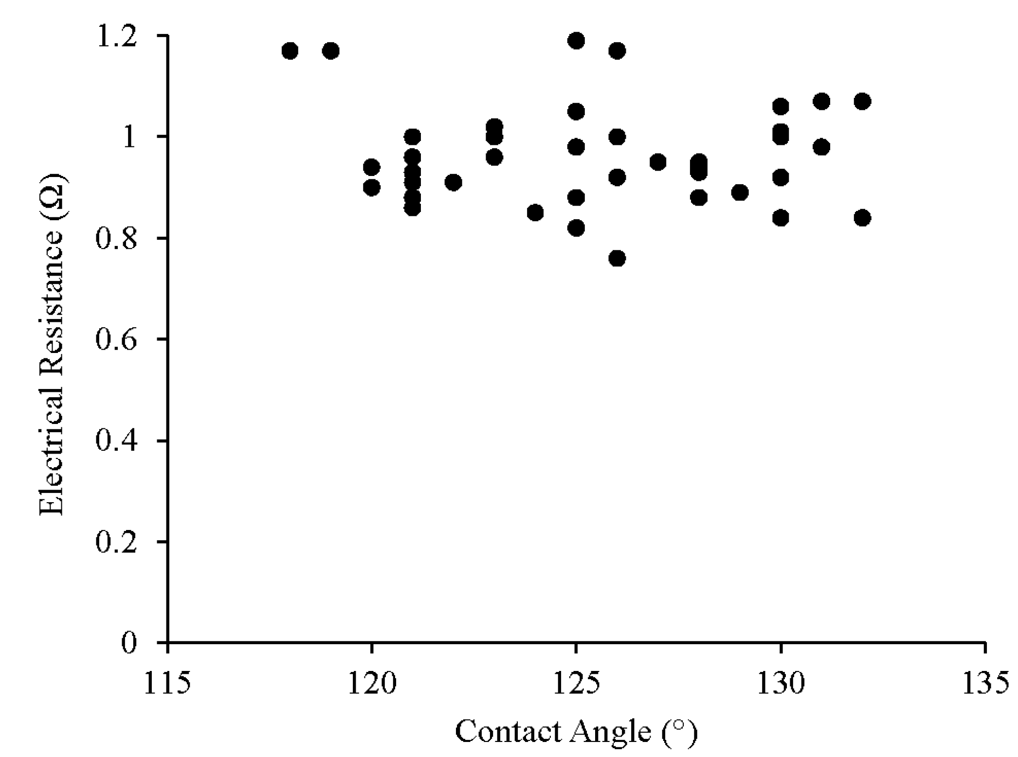
In this study, FTIR-ATR technique is used to analyse the surface functionality of laser-treated carbon fibre fabrics. FTIR-ATR technique is a simple and useful method to compare surface functional groups between untreated and laser-treated carbon fibre fabrics in addition to XPS [24].
Figure 8 shows the comparison of FTIR-ATR spectra of untreated and laser-treated carbon fibre fabric samples. It is obvious that intensity within some ranges of wavenumbers are increased after laser treatment. In the range of 2850–3000 cm−1 (Circle (a)) which represents alkane C–H functional group [25], intensity of laser-treated carbon fibre fabric is increased. This increase in C–H intensity is due to the laser etching that breaks the carbon-carbon chain in carbon fibre (e.g., formation of cracks in the fibre surface) leading to formation of new linear alkane hydrocarbon chain. In addition, in the 1400–1500 cm−1 range (Circle (d)) which represents the –CH2 and –CH3 bending [26], the formation of –CH2 and –CH3 bending can support formation of C–H functional groups as shown in the range of 2850–3000 cm−1 because of the breakdown of long carbon-carbon chains into new linear alkane hydrocarbon chains.
The region of 1670–1820 cm−1 generally represents the presence of C=O carbonyl functional group [25] on the carbon fibre surface after laser treatment and peak intensity is more obvious in 1670–1700 cm−1 (Circle (b)). The increase in peak intensity in 1670–1700 cm−1 indicates that oxygen-containing groups are introduced over the carbon fibre surface after laser treatment which may be due to the thermal oxidation effect [16,17,18]. On the other hand, peak intensity in the region 1050–1250 cm−1 (Circle (e)) is increased which represents the C–O–C [26]. Since laser treatment is carried out at atmospheric pressure, the high laser energy generated during the treatment may cause thermal oxidation effect in the presence of oxygen in air and introduce oxygen-containing functional groups as evidence in the increased peak intensities in wavenumbers 1670–1700 cm−1 and 1050–1250 cm−1. In the range 1050–1150 cm−1 [25], an evident peak ascribed to C–O functional groups is noted. The formation of new functional groups with oxygen in laser-treated carbon fibre surface improves its hydrophilicity and hence the contact angles are generally reduced.
Interestingly, there is a sharp peak in the range 1500–1600 cm−1 (Circle (c)) in the laser-treated carbon fibre fabric which may be due to the formation of N–H functional groups [26] over the carbon fibre surface. As the laser treatment is conducted at atmospheric conditions, nitrogen in the air could have formed nitrogen-containing functional groups.
To evaluate the change in surface functionality of the carbon fibre fabrics under the influence of laser treatment quantitatively, the peak ratio is calculated and summarised in Table 1. In the peak ratio analysis, the absorbance of the C–C single bond frequency at 1000 cm−1 is used as internal reference [27]. Based on the results in Table 1, the surface functionality of carbon fibre fabric is altered under the influence of laser treatment. Different quantity of function groups in the assigned peak are enhanced after laser treatment.

3.3. Contact Angle

The contact angles of different laser-treated carbon fibre fabric samples are shown in Table 2. The contact angle of untreated carbon fibre fabric is 135° (with 95% confidence level). After laser-treatment, the contact angle of the laser-treated carbon fibre fabric decreases to different extents, with the variation of pixel time and resolution. Generally, the increase in pixel time and resolution increases laser irradiation energy to interact with the substrate surface [16,17,18]. However, the level of laser irradiation energy depends on the combination of the laser process parameters of pixel time and resolution [16,17,18]. The decrease in contact angle of laser-treated carbon fibre fabric indicates that wettability of fabric is changed and the laser-treated carbon fibre fabric can absorb water easier than untreated carbon fibre fabric. This change in wettability may be due to the introduction of hydrophilic functional groups on the carbon fibre surface. Those hydrophilic functional groups may be the oxygen-containing functional groups [13]. Since laser treatment was conducted in atmospheric conditions, the high laser irradiation energy together with the ambient oxygen introduce oxygen-containing functional groups to the carbon fibre fabric surface as shown in Figure 8.

3.4. Electrical Resistance

Electrical resistance of differently laser-treated carbon fibre fabrics is shown in Table 3. The electrical resistance of untreated carbon fibre fabric is 0.90 Ω. Experimental results reveal that laser treatment does not affect electrical resistance of the carbon fibre fabric though wettability of the fabric is improved. Figure 9 depicts the correlation between contact angle and electrical resistance. There is no direct relationship between the contact angle and the electrical resistance. In the laser treatment, the interaction between laser beam and the carbon fibre fabrics is mainly in the fibre surface and the laser process affects only the fabric surface, only a thin layer of carbon fibre is removed [21,22,23], which may affect surface properties of the carbon fibre fabric such as contact angle. However, the electrical resistance property is a bulk property and the surface laser engraving process may not affect inner part of the carbon fibre fabric and hence alter the its original properties [16,20]. Therefore, a scattered relationship is noted in Figure 9.

4. Conclusions

This study investigated the effect of CO2 laser treatment with different combinations of process parameters, i.e., resolution (ranged 70–100 dpi) and pixel time (110–200 µs) on carbon fibre fabric. The CO2 laser treatment is a surface treatment which does not affect its original properties of the carbon fibre fabric. It was found that the general electrical property of the fabric did not change much after laser treatment. Even contact angles against water were decreased after CO2 laser treatment. SEM images revealed that cracks were generated on the carbon fibre surface and in an extreme case (resolution of 100 dpi and pixel time of 200 µs), deep holes were also generated on the carbon fibre surface. The formation of cracks/holes roughened the surface which made the carbon fibre fabric look darker (reduced surface lustre) than untreated carbon fibre fabric due to diffused reflection. Surface functional groups were determined by FTIR-ATR method. Obviously, oxygen-containing functional groups were introduced to the carbon fibre surface after CO2 laser treatment. Interestingly, nitrogen-containing functional groups were induced on the carbon fibre surface after CO2 laser treatment. Based on the results of this study, although the colour of carbon fibre fabric is black, CO2 laser treatment can improve its aesthetic properties by altering its light reflection behaviour. In addition, the introduced functional groups could be used for grafting of various molecules.

Author Contributions

C.-w.K. and J.-l.H. conceived and designed the experiments; Y.-d.L., K.-h.C., C.-y.H. and Y.-l.L. performed the experiments; Y.-l.L., K.-h.C. and C.-w.K. analyzed the data; Y.-d.L. and K.-h.C. drafted the paper; and C.-w.K. proofread the technical content.

Funding

Authors would like to express grateful thanks to The Hong Kong Polytechnic University for the financial support (account number: 1-ZE27 and G-UA9M).

Conflicts of Interest

The authors declare no conflict of interest.

References

  1. Frank, E.; Steudle, L.M.; Ingildeev, D.; Spörl, J.M.; Buchmeiser, M.R. Carbon fibers: Precursor, systems, processing, structure, and properties. Angew. Chem. Int. Ed. 2014, 53, 5262–5298. [Google Scholar] [CrossRef] [PubMed]
  2. Kim, J.W.; Lee, J.S. Preparation of carbon fibers from linear low density polyethylene. Carbon 2015, 94, 524–530. [Google Scholar] [CrossRef]
  3. Frank, E.; Hermanutz, F.; Buchmeiser, M.R. Carbon fibers: Precursors, manufacturing, and properties. Macromol. Mater. Eng. 2012, 297, 493–501. [Google Scholar] [CrossRef]
  4. Feldhoof, A.; Pippel, E.; Wolterdorf, J. Interface engineering of carbon fiber reinforced Mg-Al alloys. Adv. Eng. Mater. 2000, 2, 471–480. [Google Scholar] [CrossRef]
  5. Pimenta, S.; Pinho, S.T. Recycling carbon fibre reinforced polymers for structural applications: Technology review and market outlook. Waste Manag. 2011, 31, 378–392. [Google Scholar] [CrossRef] [PubMed] [Green Version]
  6. Helmer, T.; Peterlik, H.; Kromp, K. Coating of carbon fibers—The strength of the fibers. J. Am. Ceram. Soc. 1995, 78, 133–136. [Google Scholar] [CrossRef]
  7. Chen, F.; Yang, H.; Li, K.; Deng, B.; Li, Q.; Liu, X.; Dong, B.; Xiao, X.; Wang, D.; Qin, Y.; et al. Facile and effective coloration of dye-inert carbon fibers fabrics with tunable colors and excellent laundering durability. ACS Nano 2017, 11, 10330–10336. [Google Scholar] [CrossRef] [PubMed]
  8. Stepankova, M.; Wiener, J.; Rusinova, K. Decolourization of vat dyes on cotton fabric with infrared laser light. Cellulose 2011, 18, 469–478. [Google Scholar] [CrossRef]
  9. Ferrero, F.; Testore, F.; Tonin, C.; Innocenti, R. Surface degradation of linen textiles induced by laser treatment: Comparison with electron beam and heat source. AUTEX Res. J. 2002, 2, 109–114. [Google Scholar]
  10. Stepankova, M.; Wiener, J.; Dembicky, J. Impact of laser thermal stress on cotton fabric. Fiber. Text. East. Eur. 2010, 18, 70–73. [Google Scholar]
  11. Juciene, M.; Urbelis, V.; Juchneviciene, Z.; Cepukone, L. The effect of laser technological parameters on the color and structure if denim fabric. Text. Res. J. 2014, 84, 662–670. [Google Scholar] [CrossRef]
  12. Ondogan, Z.; Pamuk, O.; Ondogan, E.N.; Ozguney, A. Improving the appearance of all textile products from clothing to home textile using laser technology. Opt. Laser Technol. 2005, 37, 631–637. [Google Scholar] [CrossRef]
  13. Hung, O.N.; Kan, C.W. A study of CO2 laser treatment on the colour properties of cotton-based Fabrics. Coatings 2017, 7, 131. [Google Scholar] [CrossRef]
  14. Hung, O.N.; Chan, C.K.; Kan, C.W.; Yuen, C.W.M.; Song, L.J. Artificial neural network approach for predicting colour properties of laser-treated denim fabrics. Fiber. Polym. 2014, 15, 1330–1336. [Google Scholar] [CrossRef]
  15. Kan, C.W. Colour fading effect of indigo-dyed cotton denim fabric by CO2 laser. Fiber. Polym. 2014, 15, 426–429. [Google Scholar] [CrossRef]
  16. Hung, O.N.; Chan, C.K.; Kan, C.W.; Yuen, C.W.M. Microscopic study of the surface morphology of CO2 laser-treated cotton and cotton/polyester blended fabric. Text. Res. J. 2017, 87, 1107–1120. [Google Scholar] [CrossRef]
  17. Hung, O.N.; Chan, C.K.; Kan, C.W.; Yuen, C.W.M. Effect of the CO2 laser treatment on properties of 100% cotton knitted fabrics. Cellulose 2017, 24, 1915–1926. [Google Scholar] [CrossRef]
  18. Hung, O.N.; Chan, C.K.; Kan, C.W.; Yuen, C.W.M. An analysis of some physical and chemical properties of CO2 laser-treated cotton-based fabrics. Cellulose 2017, 24, 363–381. [Google Scholar] [CrossRef]
  19. Kan, C.W.; Yuen, C.W.M. Effect of atmospheric pressure plasma treatment on wettability and dryability of synthetic textile fibres. Surf. Coat. Technol. 2013, 228, S607–S610. [Google Scholar] [CrossRef]
  20. Hung, O.N.; Kan, C.W. Effect of CO2 laser treatment on the fabric hand of cotton and cotton/polyester blended fabric. Polymers 2017, 9, 609. [Google Scholar] [CrossRef]
  21. Blaker, J.J.; Anthony, D.B.; Tang, G.; Shamsuddin, S.-R.; Kalinka, G.; Weinrich, M.; Abdolvand, A.; Shaffer, M.S.P.; Bismarck, A. Property and shape modulation of carbon fibers using lasers. ACS Appl. Mater. Interfaces 2016, 8, 16351–16358. [Google Scholar] [CrossRef] [PubMed] [Green Version]
  22. Finger, J.; Weinand, M.; Wortmann, D. Ablation and cutting of carbon-fiber reinforced plastics using picosecond pulsed laser radiation with high average power. J. Laser Appl. 2013, 25, 042007. [Google Scholar] [CrossRef]
  23. Voisey, K.T.; Fouquet, S.; Roy, D.; Clyne, T.W. Fibre swelling during laser drilling of carbon fibre composites. Opt. Lasers Eng. 2006, 44, 1185–1197. [Google Scholar] [CrossRef]
  24. Yuan, H.; Wang, C.G.; Zhang, S.; Lin, X. Effect of surface modification on carbon fiber and its reinforced phenolic matrix composite. Appl. Surf. Sci. 2012, 259, 288–293. [Google Scholar] [CrossRef]
  25. Characteristic IR Absorption Frequencies of Organic Functional Groups. Available online: http://www2.ups.edu/faculty/hanson/Spectroscopy/IR/IRfrequencies.html#carbonylIR (accessed on 5 January 2018).
  26. Infrared Spectroscopy Table. Available online: http://www.chem.ucla.edu/~bacher/General/30BL/IR/ir.html (accessed on 5 January 2018).
  27. Kan, C.W.; Yuen, C.W.M. Plasma technology in wool. Text. Prog. 2007, 39, 121–187. [Google Scholar] [CrossRef]
  28. Geroge, K.M.; Ruthenburg, T.C.; Smith, J.; Yu, L.; Zhang, Q.; Anasyasio, C.; Dillner, A.M. FT-IR quantification of the carbonyl functional group in aqueous-phase secondary organic aerosol from phenols. Atmos. Environ. 2015, 100, 230–237. [Google Scholar] [CrossRef]
  29. Cecen, V.; Seki, Y.; Sarikanat, M.; Tavman, I.H. FTIR and SEM analysis of polyester- and epoxy-based composites manufactured by VARTM process. J. Appl. Polym. Sci. 2008, 108, 2163–2170. [Google Scholar] [CrossRef]
Figure 1. Laser profile on carbon fibre fabric with different pixel time and resolution.
Coatings 08 00178 g001
Figure 2. SEM image of untreated carbon fibre fabric.
Coatings 08 00178 g002
Figure 3. SEM image of carbon fibre fabric treated with laser parameter of 70 dpi and 110 µs.
Coatings 08 00178 g003
Figure 4. SEM image of carbon fibre fabric treated with laser parameter of 100 dpi and 110 µs.
Coatings 08 00178 g004
Figure 5. SEM image of carbon fibre fabric treated with laser parameter of 70 dpi and 200 µs.
Coatings 08 00178 g005
Figure 6. SEM image of carbon fibre fabric treated with laser parameter of 100 dpi and 200 µs: (a) 7000×; and (b) 15,000×.
Coatings 08 00178 g006
Figure 7. Reflection of light from: (a) untreated carbon fibre surface and (b) laser-treated carbon fibre surface.
Coatings 08 00178 g007
Figure 8. FTIR spectra of untreated and laser-treated carbon fibre fabric sample (70 dpi and 110 µs). (a) 2850–3000 cm−1; (b) 1670–1700 cm−1; (c) 1500–1600 cm−1 ; (d) 1400–1500 cm−1; (e) 1050–1250 cm−1.
Coatings 08 00178 g008
Figure 9. Relationship plot between contact angle and electrical resistance.
Coatings 08 00178 g009
Table 1. Peak ratio.
Functional GroupPeak Range (cm−1)Assigned Peak (cm−1)Peak Ratio
Control70 dpi/110 µs
C–H2850–30003000 [28]1.111.17
C=O1670–18201700 [28]1.081.12
N–H1500–16001600 [25]1.081.11
–CH2 and –CH3 1400–15001453 [29]1.071.10
C–O–C1050–12501121 [29]1.031.06
Note :   Peak   ratio =   Absorbance   at   assigned   peak Absorbance   at   C C   sin gle   bond   frequency   at   1000   cm 1   .
Table 2. Contact angle value (°).
Pixel Time ( µs)110120130140150160170180190200
Resolution (dpi)
70131130130132128127121121121126
80132130130130129125121123124126
90120121122131125123121118119120
100128126125128128123121125126125
Table 3. Electrical resistance (Ω).
Pixel Time ( µs)110120130140150160170180190200
Resolution (dpi)
701.071.011.061.070.930.950.860.910.961.00
800.840.840.921.000.890.820.880.960.850.92
900.940.930.910.980.981.001.001.171.170.90
1000.940.760.880.880.951.021.001.051.171.19

