Article

Stress-Affected Lithiation Reactions in Elasto-Viscoplastic Si Particles with Hyperelastic Polymer Coatings: A Nonlinear Chemo-Mechanical Finite-Element Study

1
International Institute for Nanocomposites Manufacturing, WMG, University of Warwick, Coventry CV4 7AL, UK
2
Warwick Centre for Predictive Modelling, University of Warwick, Coventry CV4 7AL, UK
*
Author to whom correspondence should be addressed.
Coatings 2018, 8(12), 455; https://doi.org/10.3390/coatings8120455
Submission received: 13 November 2018 / Revised: 30 November 2018 / Accepted: 6 December 2018 / Published: 8 December 2018
(This article belongs to the Special Issue Modelling and Simulation of Coating 2019)

Abstract

:
Stress-affected two-phase lithiation reactions in spherical elasto-viscoplastic Si particles for Li-ion batteries are studied here to determine the effects of a hyperelastic polymer coating on particle stresses, reaction front velocity, and degree of lithiation. The problem is modelled using finite-strain chemo-mechanical equations that couple stress, with Li-ion diffusion and reaction front velocity, and are solved using the finite-element (FE) approach, taking advantage of spherical symmetry of the problem. FE simulations and the sensitivity analysis reveal: (1) coating thickness is the most influential design parameter that affects the velocity of the reaction front, and (2) increasing values of the coating shear and bulk moduli, and the coating thickness reduce tensile circumferential stresses at the edge of the particle. The latter minimises the risk of particle cracking in the opening mode, but it can also accelerate the arrest of the reaction front, and thus reduce the particle lithiation degree in Li-ion battery anodes.

Graphical Abstract

1. Introduction

Lithium-ion batteries (LIBs) are some of the most widely employed energy storage devices, used in a range of applications such as electric vehicles, large-scale energy storage grids, and portable electronic devices [1,2,3]. While most commercial LIBs use graphite as an active anode material, silicon (Si) particles have been the subject of intense research in recent years as a possible replacement, as depending on form, Si has approximately 10 times the capacity of graphite [4,5,6]. However, the main drawback is that Si particles undergo large volumetric expansion during lithiation (over 300%) [7,8], compared to that of graphite (~10%) [9]. The expansion of Si during lithiation leads to severe mechanical stresses in the anode material over multiple cycles, which can lead to cracking of the surface of the particle [10,11]. As a result, the gravimetric capacity of LIBs using Si can decrease over a number of cycles (70% capacity loss within five cycles) [12], partially negating the main advantage of using Si.
Several approaches have been proposed to reduce the capacity fade of LIBs by decreasing mechanical stresses. These include using nanometre-size Si particles to reduce crack formation [13,14,15], and applying coatings made from a range of materials [16,17,18,19]. Coatings mechanically constrain each particle and also protect the active material from coming into contact with the electrolyte of the battery [16,17,18], which leads to the growth of an undesirable solid electrolyte interphase (SEI). Different coatings have shown to improve cycling performance, with a polymer coating allowing for a capacity retention of over 90% for 5000 cycles [18], and a carbon coating leading to a retention of 95.6% of the initial capacity after 40 cycles [20]. Stresses in LIB not only lead to mechanical deterioration of the constituents, but also interfere with the kinetics of lithiation reaction [4]. The mechanochemical coupling mechanisms are already well-studied in literature, e.g., [21,22,23,24]. However, a detailed study of how polymer coatings influence the stress-affected lithiation process in Si particles of LIB anodes is yet to be performed. Due to their complexity, systematic in situ experimental studies on the influence of coatings on the lithiation process of Si particles are scarce [25]. In addition to experiments, there have been few computational modelling studies on the topic of coated Si particles undergoing lithiation reaction. For example, Li et al. [26] utilised a linear elastic model to optimise carbon-coated Si particles to improve capacity retention by varying coating radius, coating thickness, and space between the expanding particle and the carbon coating. Although the proposed study provided some useful qualitative direction for maximising the capacity of carbon-coated Si particles, the analysis did not capture the lithiation-reaction in Si particles observed experimentally. It is well-known that the two-phase lithiation process occurs in Si particles, with the lithiated material separated from the unlithiated one by a reaction front which is driven by an electrochemical force [27,28]. To capture this phenomenon, a finite-element study investigated the effects of fracture of the carbon coating surrounding a Si particle with a stationary sharp reaction front separating lithiated and unlithiated parts of the particle [29]. The authors proposed some design guidelines for the thickness of the carbon coating. The models of non-stationary stress-affected two-phase reaction front, in turn, have been reported in [30,31], and implemented into a nonlinear finite-element framework. Up to now, neither of these approaches have been extended to study coated particles using nonlinear finite-element simulations, important for the design of enhanced Si particle-based electrodes of LIBs.
The aim of this paper is twofold. First, a nonlinear chemo-mechanical model [30] that captures stress-affected two-phase lithiation as a non-stationary reaction process in Si particles is extended to account for the presence of a polymer coating around Si particles. Second, the extended model is implemented into a nonlinear large-strain finite-element framework to enable simulations of the stress-affected lithiation reaction in polymer-coated Si particles, and provide new insights into the effects of material properties and thickness of a polymer coating on stresses, reaction front velocity, and degree of lithiation.

2. Chemo-Mechanical Model for a Polymer-Coated Spherical Si Particle

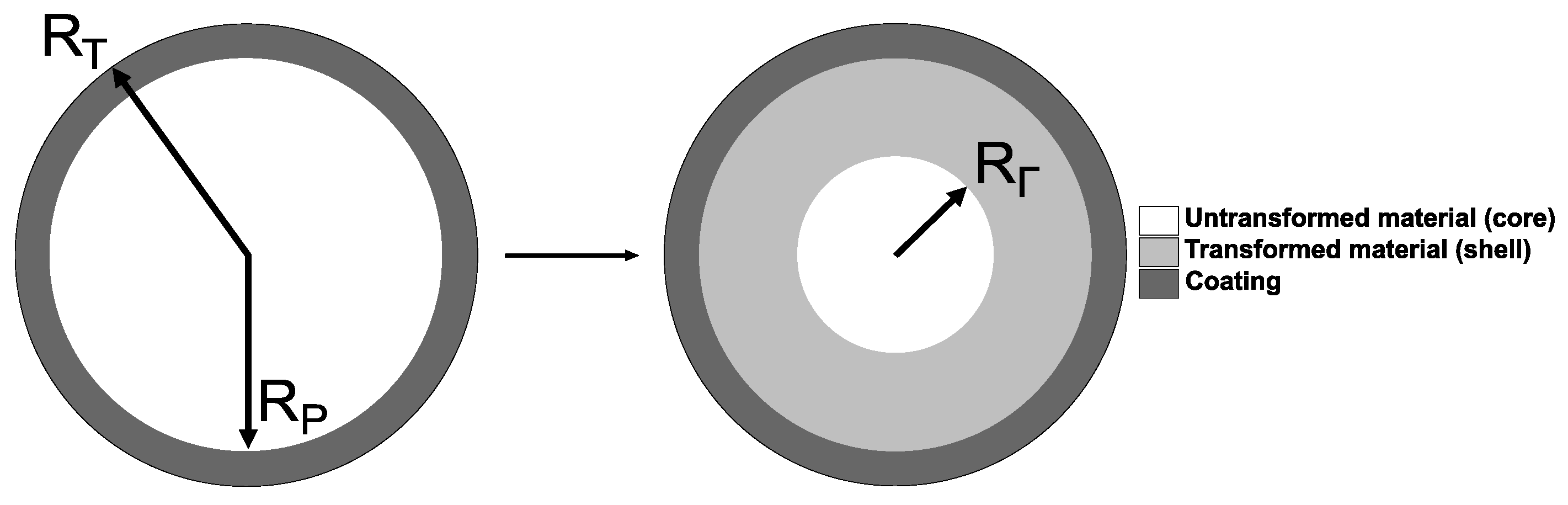
2.1. Model Background

The computational chemo-mechanical model follows the thermodynamic theoretical framework of chemical reactions based on the chemical affinity tensor for localised chemical reactions in deformable materials, originally developed by Freidin et al. [24,32,33], and it is an extension of the model of two-phase lithiation of spherical Si particles without a coating [30].
Here, a spherical amorphous Si (a-Si) particle surrounded by a hyperelastic polymer layer of uniform thickness is considered, as shown in Figure 1. The bonding strength between the coating and particle is assumed as infinitely high, and thus no debonding is considered in this work. Moreover, the model neglects the presence of a solid electrolyte interphase (SEI) layer [18,33,34], due to the lack of experimental evidence about the effect of the coating on the occurrence of the SEI.
The lithiation process starts here from the edge of Si particle rather than from the edge of the coating. When the lithiation reaction occurs between a solid constituent (Si particle) and a diffusive constituent (Li ions), the latter diffuses through the chemically transformed part of Si particle, the reaction is localised at an infinitely thin interface (reaction front). The lithiation process is described by the chemical formula n(a-Si) + n Li → Li n ( a Si ) n , where it is assumed that the transformed material has 3.75 lithium atoms per one Si atom (i.e., Li3.75(a-Si))—this in line with the previously published papers (see e.g., [27]), where the ratio of stoichiometric coefficients n /n varies from 2.5 to 3.75. In addition, the maximum achievable concentration of Li ions in a-Si, taken here as 4.4 (Li) to 1 (a-Si) ratio, is used to calculate solubility (see [30])–the latter also signifies that there are 0.65 free Li atoms (per 1 a-Si atom) available for the diffusion process.
The reaction front separates the transformed (shell) and untransformed (core) domains of the particle (see the right-hand side part of Figure 1). The chemical transformation of the shell domain leads to the volumetric expansion g, which is assumed as isotropic. As a result, mechanical constraints provided by the untransformed core and hyperelastic coating to the volumetrically expanding shell lead to stresses within the entire particle. In turn, those stress affect the kinetics of the reaction front, according to the thermodynamic theory of localised reactions [24,32,33]. Thus, the problem here involves three coupled processes of mechanical deformation, diffusion, and chemical reaction at the reaction front, which contribute to the formulation of the coupled system of governing equations, described in the section below (see Section 2.2).
It is noteworthy to mention that the lithiation reaction for crystalline Si particles (c-Si) will lead to an anisotropic expansion, and will induce preferential expansion of the particle, as confirmed by experiments [11]. This will require formulation and solution of the coupled system of equations in 3D, including a computationally challenging task of resolving the movement of the reaction front in 3D.

2.2. Governing Equations for a Coated Spherical Si Particle With a Non-Stationary Reaction Front

The governing equations of the model are formulated in the spherical coordinate system due to the spherical symmetry of the problem.
The kinematics of the particle is described by the total, and plastic deformation gradients F and Fp, respectively, which are given as
F _ = d r _ d R e R e R + r _ R ( I e R e R )
F + = d r + d R e R e R + r + R ( I e R e R )
F p =   p e R e R + 1 ( λ p ) 1 / 2 ( I e R e R )
where subscripts “−” and “+” refer to the untransformed (core) and transformed (shell) particle domains, respectively; e R is the base vector in the radial direction, r is the radial coordinate in the current configuration and R is the radial coordinate in the reference configuration, while λ p denotes the plastic stretch ratio in the radial direction.
The linear momentum balance equation is given by:
d σ R d R + 2 R ( σ R σ θ ) = 0
where σ R and σ θ are the radial and the circumferential Cauchy stress components, respectively.
The stress components are defined within the separate phases as:
  σ R = { σ R   ( R ) , R < R Γ σ R +   ( R ) , R Γ < R < R P σ R T   ( R ) , R > R P
σ θ = { σ θ   ( R ) , R < R Γ σ θ +   ( R ) , R Γ < R < R P σ θ T   ( R ) , R > R P
Equation (2) is complemented with relevant interface (at the reaction front) and boundary conditions: (i) the displacement and traction continuity conditions are enforced at the position of the reaction front R Γ as well as at R P , (ii) the external boundary condition is enforced at R T (for the majority of simulation cases, the stress-free particle boundary was assumed here).
The normal component of the stress-dependent velocity of the reaction front, near chemical equilibrium, is given by [32]:
V = d R Γ d t = n M ρ k n ( c c eq )
where c denotes the Li-ion concentration at the reaction front, n and n are the stoichiometric coefficients related to the untransformed material (core of the particle) and diffusive species (Li ions). Furthermore, ρ is the mass density and M is the molar mass of Si particle, respectively; k is the reaction rate coefficient, and c eq is the concentration at which the chemical equilibrium occurs.
For spherical symmetry, the equilibrium concentration c eq for a current position of the reaction front can be found as [32]:
c eq = c exp ( 1 R g T n M ρ ( γ + W g 3 W + + r 2 R 2 σ R d r d R ) )
where dr/dR in the double brackets denote the jump of the radial component of the total deformation gradient at the reaction front. Then, c stands for the solubility of Li ions in the transformed material, γ is the chemical energy parameter consisting of the temperature-dependent chemical energies of the reaction constituents; while W and W + stand for the strain energy density of the untransformed and transformed materials, respectively (see Section 2.3). Finally, R g is the ideal gas constant and T stands for temperature. Hence, the reaction front velocity is coupled with the mechanics via the radial stress component and the jump of the radial component of the total deformation gradient, as shown in Equation (5).
Then, assuming that the diffusion process for Li-ions is much faster than the reaction front propagation, one can find the concentration of Li-ions at the reaction front by solving a steady-state diffusion equation as:
1 R 2   d d R ( R 2 d c d R ) = 0
complemented by two boundary conditions [30]:
D d d R c + ( n ) 2 k ( c c e q ) | R = R Γ = 0
D d d R c + α ( c c ) | R = R P = 0
where D is the diffusion coefficient of the Li ions through the transformed (lithiated) material, respectively; α is the surface mass transfer coefficient. The Li-ion diffusion equation (cf. Equation (6)) can be solved analytically in the form of c(r) = C1 + C2 r, where the coefficients C1 and C2 are determined from the boundary conditions (cf. Equations (7) and (8)).
The concentration obtained from the solution of Equations (6)–(8), it can then be substituted to Equation (4) to give the following expression for the velocity of the reaction front (for n = 1 )
V = ( c c eq ) n M ρ 1 1 k + ( 1 ξ ) 2 α + ξ ( 1 ξ ) D 0
where
ξ = R P R Γ R P       and   ξ = [ 0 , 1 ] ,     D 0 = D R P
The governing equations given above form a coupled stress-diffusion-reaction boundary value problem for a polymer-coated Si particle, which are complemented by relevant constitutive equations described in the section below.

2.3. Constitutive Relations

2.3.1. Transformed and Untransformed Components of Si Particle

Constitutive (stress–strain) relations for lithiated (phase transformed) and unlithiated (phase untransformed) parts of Si particles are derived from the corresponding strain energy density functions for the transformed and untransformed domains of the particle. Tensor derivations are omitted below and only the final expressions are provided—for further details, see [30].
The strain energy density function for the untransformed material is given as
W = K ( r 3 R 3 1 ln r 3 R 3 )
with the bulk modulus of the untransformed material given by K .
Thus, the corresponding stress components are given by:
σ R = σ θ = K ( 1 R 3 r 3 )
The strain energy density of the transformed material, W + , is described by:
W + =   K + ( χ ζ 1 ln χ ζ ) + G s 2 ( 1 λ p 2 χ 4 3 + 2 λ p χ 2 3 3 ) + G h 2 ( χ 4 3 + 2 χ 2 3 3 )
where
ζ = g 3 R 3 r 3 ,                     χ = d r d R R r
and G s is the shear modulus, G h is the hardening modulus, g 3 is the ratio of volumetric expansion caused by the chemical reaction, K + is the bulk modulus.
The radial and circumferential components of the Cauchy stress tensor for the transformed material, σ R + and σ θ + , are subsequently split into their deviatoric (with superscript “d”) and volumetric (with subscript “v”) terms as follows:
σ R + = σ v R + σ   s R d + σ   h R d ,     σ θ + = σ v θ + σ   s θ d + σ   h θ d
Further, the volumetric radial and circumferential stress components are given by:
σ v R = σ v θ = K + ( 1 ζ χ )
The deviatoric stresses are subsequently separated into relevant terms that determine the nonlinear viscoelastic ( σ   s d ) and hardening ( σ   h d ) behaviour, respectively.
σ   s R d =   2 3 G s ζ χ ( 1 λ p 2 χ 4 3 + λ p χ 2 3 ) ,     σ   s θ d = 1 3 G s ζ χ ( 1 λ p 2 χ 4 3 + λ p χ 2 3 )
σ   h R d = 2 3 G h ζ χ ( χ 4 3 + χ 2 3 ) ,     σ   h θ d = 2 3 G h ζ χ ( χ 4 3 + χ 2 3 )
The description of the evolution law for plastic strains in the phase-transformed part of Si particle completes the constitutive model as:
1 λ p   d λ p   d t = 1 3 η σ s = 1 3 τ 0 σ s σ 0   ( | σ s | σ 0   ) q ,                     and                     σ s = σ s R d + σ s θ d
where τ 0 , σ 0   , and q are parameters determining the plastic flow, η is the viscosity, and σ s is the signed equivalent deviatoric driving stress.

2.3.2. Hyperelastic Polymer Coating

The polymer coating is assumed to follow a hyperelastic material behaviour, and it is described by the strain energy density function as
W T = K T ( χ ψ 1 ln χ ψ ) + G T 2 ( χ 4 3 + 2 χ 2 3 3 )
where K T and G T are the bulk and shear moduli of the coating.
Hence, the stress components in the radial and circumferential directions are given by
σ R T = K T ( 1 χ ψ ) + 2 3 ( G T χ ψ ( χ 4 3 + 2 χ 2 3 ) )
σ θ T = K T ( 1 χ ψ ) 1 3 ( G T χ ψ ( χ 4 3 + 2 χ 2 3 ) )
where the dimensionless parameter ψ is expressed as:
ψ = R 3 r 3
It is worth mentioning that the polymer coating will be subjected to electrolyte fluid in a Li-ion battery, which can change mechanical properties of the coating due to polymer swelling. However, this has not been considered here due to the lack of reliable experimental evidence.

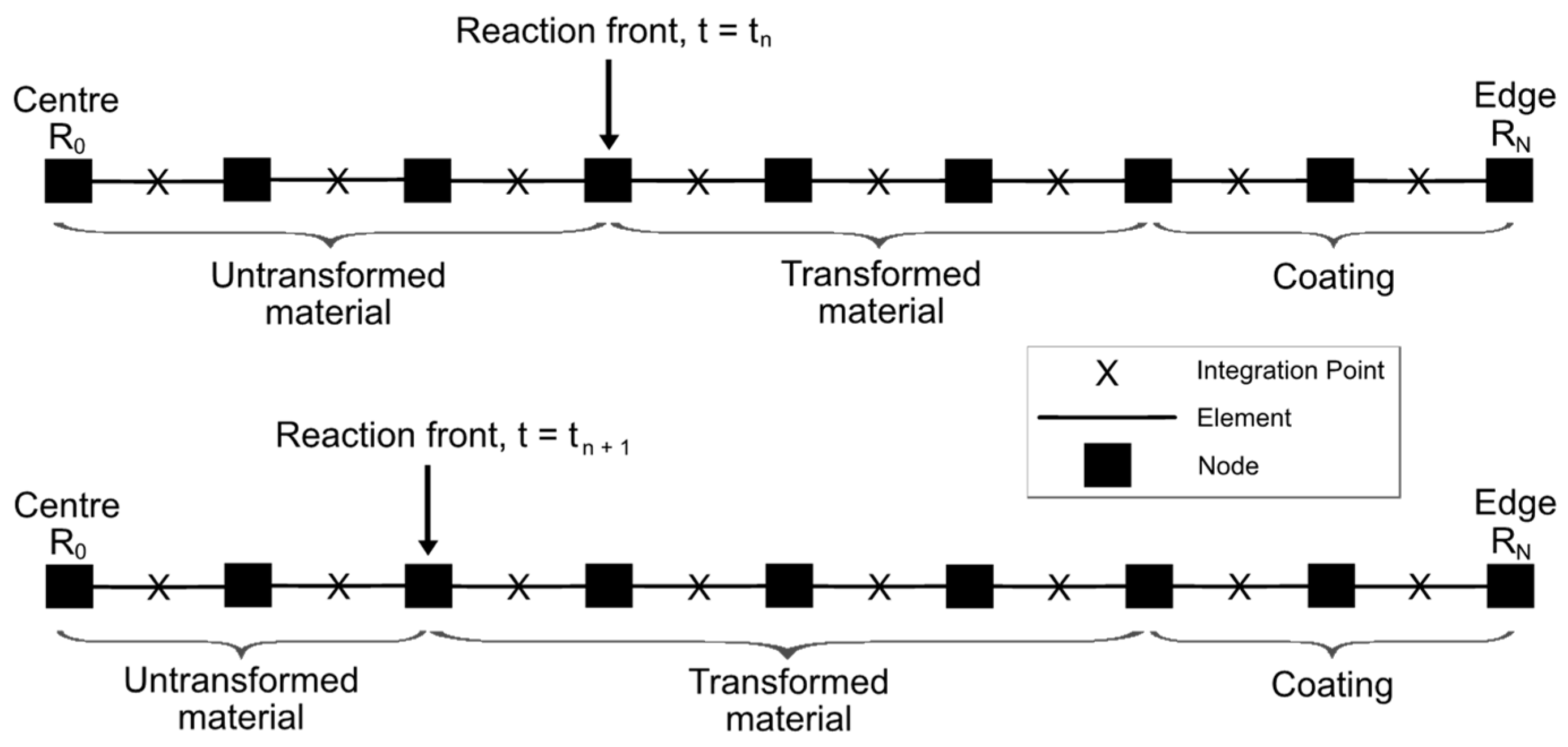
3. Finite Element solution of the Problem

The FE solution of the linear momentum balance Equation (2), subject to relevant boundary conditions (the displacement continuity at R = RΓ, and either stress-free or fully-constrained conditions at R = RT), follows a 1D numerical solution procedure due to the spherical symmetry of the problem. Thus, the problem is discretised by dividing the entire particle domain with the coating R T into ( N + 1 ) equally spaced nodes, each separated by the fixed distance Δ R = R0/N, where R0 denotes the centre of the particle. The corresponding 1D FE mesh is shown in Figure 2, with the reaction front moving by one node towards the centre in a single timestep between the two time instances t = tn and tn+1, transforming previously chemically untransformed finite-element domains in the process. Thus, the position of the reaction front can only be at nodal points of the mesh.
The model outlined in Section 2 results in ( N + 1 ) non-linear equations with unknows r i ( 1 , , N ) and Δ t . In particular, function r ˜ ( R ) gives the FE approximation of the solution to Equation (2) as:
r ˜ = i = 1 N r i ϕ i ,         and   ϕ i ( R j ) = { 1 ,     j = i , 0 ,     j i ,     R j = j Δ R ,     j = 1 , , N
where ϕ i are continuous functions of R , and are linear for R [ R j 1 ; R j ] and j .
Then, the finite-element discretisation of the momentum balance equation in spherical coordinates is given by:
0 R T σ R d ϕ i d R   d R + 0 R T 2 R ( σ R σ θ ) ϕ i   d R = 0 ,     i = 1 , ,   N
where the integrals above are evaluated at the integration point in the middle of a finite element using the mid-point rule.
Furthermore, the plastic flow rule, Equation (19), is discretised using the implicit scheme
λ p , j = λ p , j 1 exp ( 1 3 η σ   s , j Δ t )
where subscripts j and j−1 stand for the current and previous timesteps, respectively.
As the position of the reaction front at a given timestep is associated with nodal positions, the change in the front position is defined by an additional equation Δ R = V Δ t . For the fixed spatial step Δ R , the timestep Δ t becomes an additional unknown in the solution. Thus, the velocity of the reaction front V (cf. Equation (9)) is computed at the current position of reaction front R Γ i , while the timestep is the time increment required for the front to move from the previous position R i 1 to R i .
It is also worth mentioning that as the reaction front can only be located at a node, a finite element can either stand for the transformed (shell) or the untransformed (core) material domain, when adjacent to the front. Therefore, the radial stress at the reaction front required to compute c eq (cf. Equation (5)) is computed as average of stresses from the finite-element integration points on both sides of the reaction front. Moreover, strain energy and stretch ratios at integration points in transformed and untransformed finite-element domains next to the reaction front are used to compute c eq (Equation (5)), and then the velocity of the reaction front (Equation ((9)).
The solution to the resulting system of (N + 1) nonlinear equations is obtained using the Newton–Raphson method for the nodal values ri and timestep Δ t . The entire numerical procedure was implemented via MATLAB scripting.

4. Results and Discussion

The model described above is used to simulate the stress-affected two-phase lithiation in a polymer-coated Si particle to provide insights into the effects of polymer coating properties (shear modulus, bulk modulus, and thickness) on relevant stress components (radial and circumferential), degree of lithiation and the velocity of the propagating reaction front. Additionally, a simple deterministic sensitivity analysis is carried out to identify the most significant coating parameters that affect the two-phase lithiation process in a polymer-coated Si particle.

4.1. Model Parameters

Shear modulus, bulk modulus, and thickness of the polymer coating are chosen as design parameters in this paper, and their values are discussed first. The coating thickness is assumed to vary from h = 10−1 nm to h = 102 nm, which is in agreement with some coating thicknesses reported in the literature. For example, a polymer-based particle coating made of polypyrrole (PPy) with a thickness of 5–10 nm was applied to Si nanoparticles with diameters of 150 nm and 380 nm [19]. Shear moduli of typical polymers at room temperature range from a few tenths of MPa (cross-linked rubbers) to several GPa (thermosetting resins). However, here a wider range of the shear moduli from GT = 10−2 GPa to GT = 101.5 GPa is investigated, which is well beyond currently existing polymers. Nevertheless, this extended range enables a more systematic parametric study, and it also provides an incentive for developing new polymeric materials with enhanced mechanical properties for energy storage-related applications. A similarly wide range of bulk moduli is studied from KT = 10−2 GPa to KT = 101.5 GPa, where a typical value of bulk modulus for polymers is at the order of a few GPa–again, that extended range allows for a more systematic study of the influence of polymer coating properties on the lithiation process. A radius of RP =150 nm was chosen for Si particles, based on the previous research [34]. All other parameters used are given in Table A1 in Appendix A.

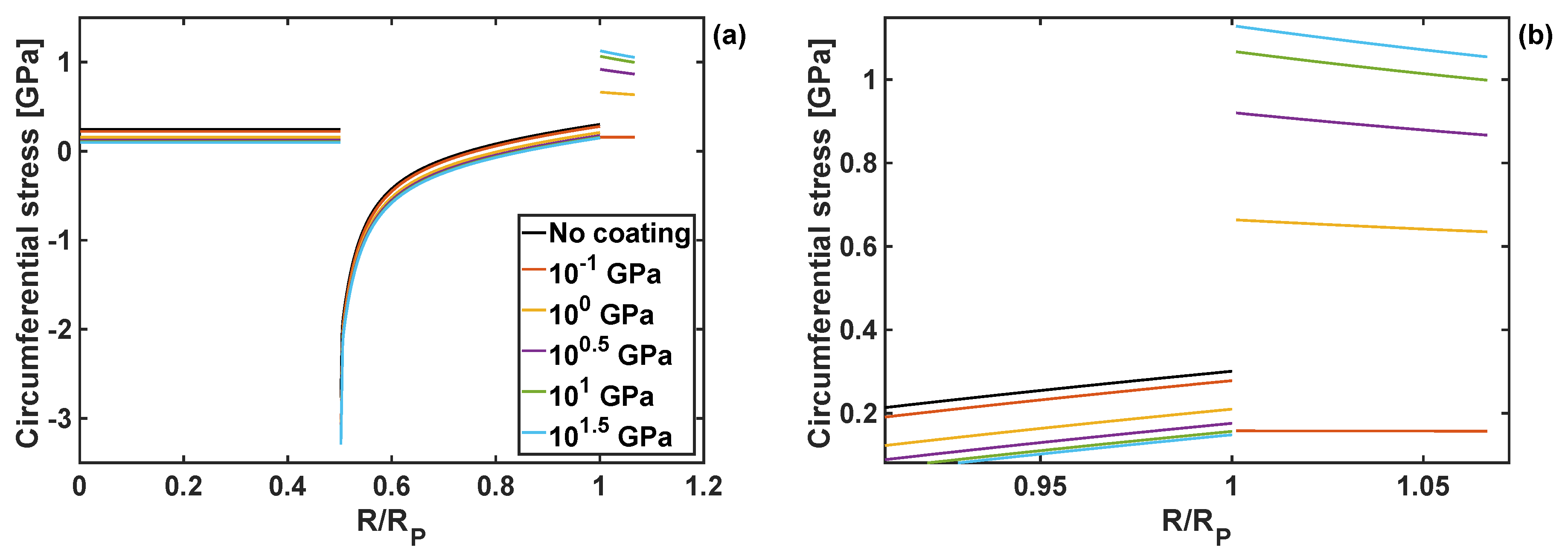
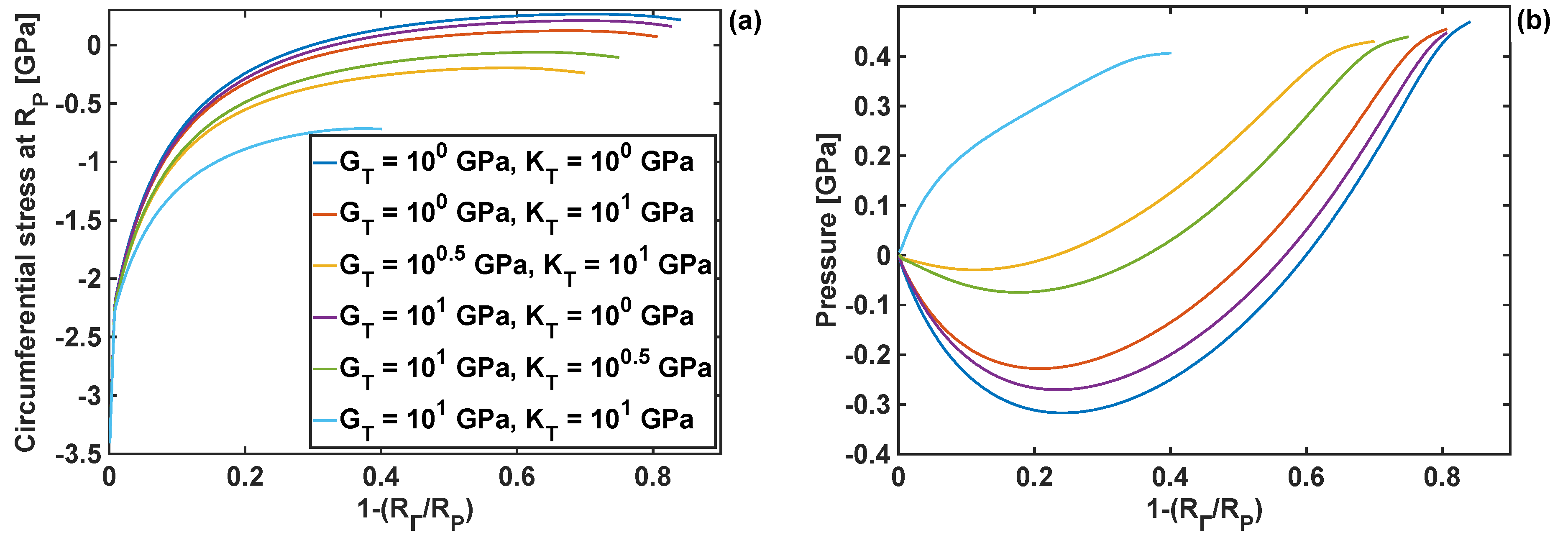
4.2. Effects of Coating Moduli on Stresses During Lithiation Process

Examples of the radial and circumferential stress components are plotted in Figure 3 and Figure 4, respectively. They are shown as a function of the normalised particle radius, for different values of the shear modulus of the coating, and at the position of reaction front corresponding to R Γ = 0.5 R P . Both radial and circumferential stresses are constant within the particle core ( R < R Γ ) due to exclusively hydrostatic stress state of the core. Outside the core (i.e., for R > R Γ ) the particle shell is subjected to compressive radial stresses, which then raise to 0 at the particle edge due to imposed stress-free boundary conditions. The circumferential stresses are discontinuous at the reaction front (i.e., at R = R Γ ), increasing from large compressive values to tensile at the edge of the particle (i.e., at R = Rp). Those complicated stress profiles result from the accumulation of the plastic deformation in the core, and were discussed in detail for the case of Si particles without the coating layer (see [30]).
The shape of those stress profiles remain qualitatively the same within the particle domain, when coatings of different properties are applied to the particle. However, the coating properties change the results quantitatively, and in some cases those changes are significant. In particular, an increase in the shear modulus of the coating leads to the reduction of tensile radial stresses in the particle core, and an increase in compressive radial stresses in the particle shell. Importantly, an increase in the coating shear modulus reduces the circumferential stresses at the edge of the particle, Figure 4b, which minimises the risk of particle cracking.
Due to the importance of the circumferential stresses at the edge of the particle (at R = Rp), those stresses were investigated further at different levels of lithiation. The results are plotted in Figure 5a for six different combinations of shear and bulk moduli. Compressive circumferential stresses are found to be dominant in the initial stages of lithiation (up to R Γ = 0.6 R P ). As the reaction front moves, the stresses become tensile for three different combinations of coating properties ( G T = K T = 1   GPa ; G T = 1   GPa and K T = 10   GPa ; G T = 10   GPa and K T = 1   GPa )—this in principle indicates that those combinations can lead to particle cracking (in opening mode I) at advanced stages of the lithiation process. The circumferential stresses never become tensile for the moduli combination of G T = K T = 10   GPa –coatings with those moduli values would prevent from opening mode I particle fracture from the particle edge. Figure 5b shows pressure, p   = R at the reaction front, plotted as a function of the reaction front position for different moduli combinations. Similarly, as for the circumferential stresses at the edge of the particle, there is a large discrepancy in the results when the moduli combination is G T = 10 GPa and K T = 10 GPa. In particular, this moduli combination results in a constant rise in pressure at the reaction front during the lithiation, while in the case of the other moduli combinations the pressure becomes negative up to R Γ = 0.8 R P , and only then it starts to increase.

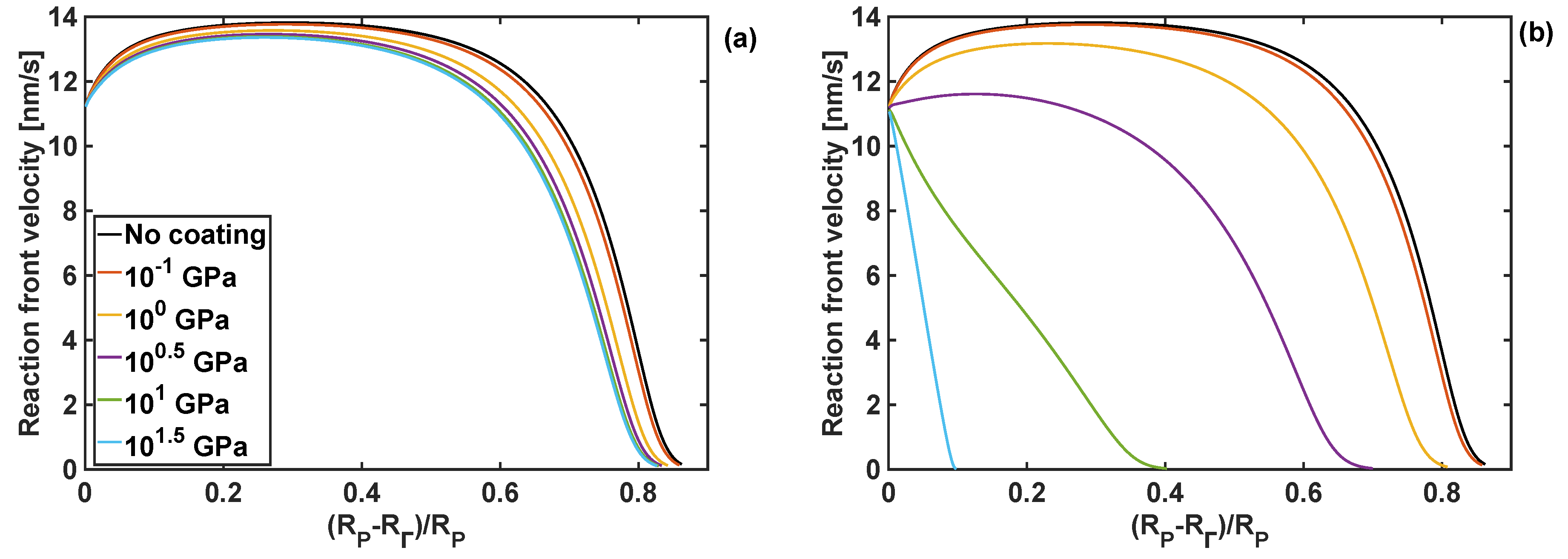
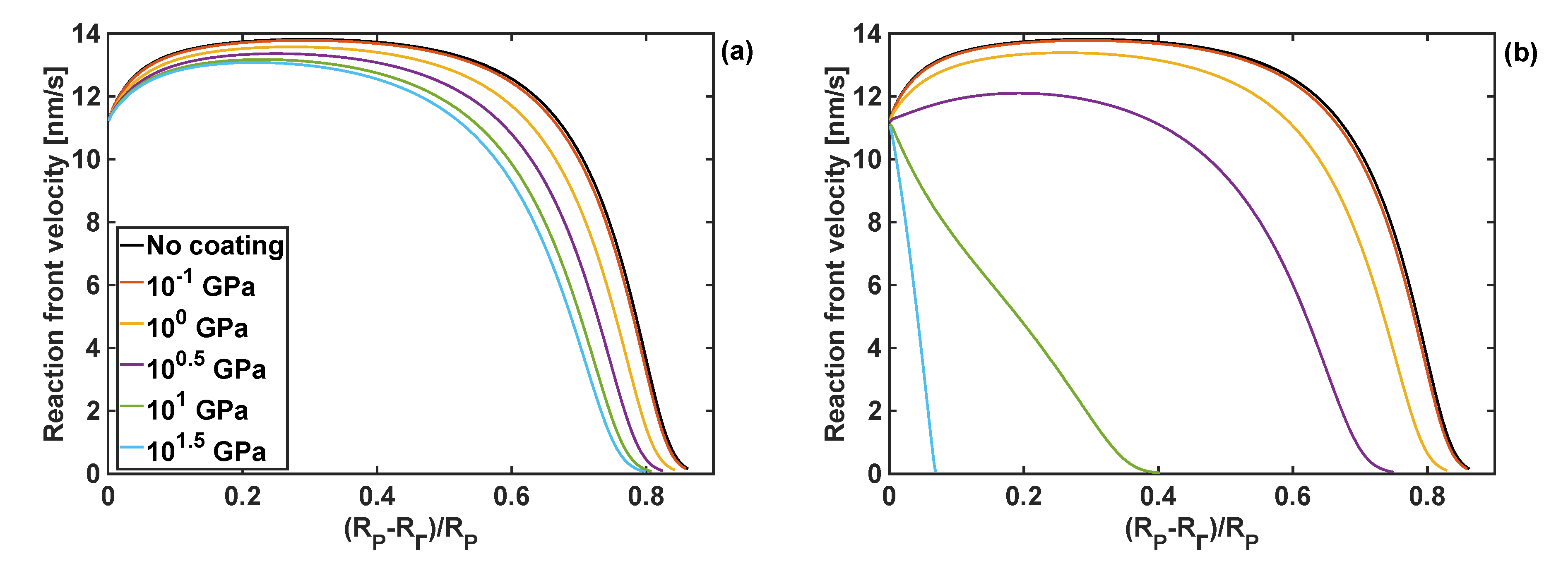
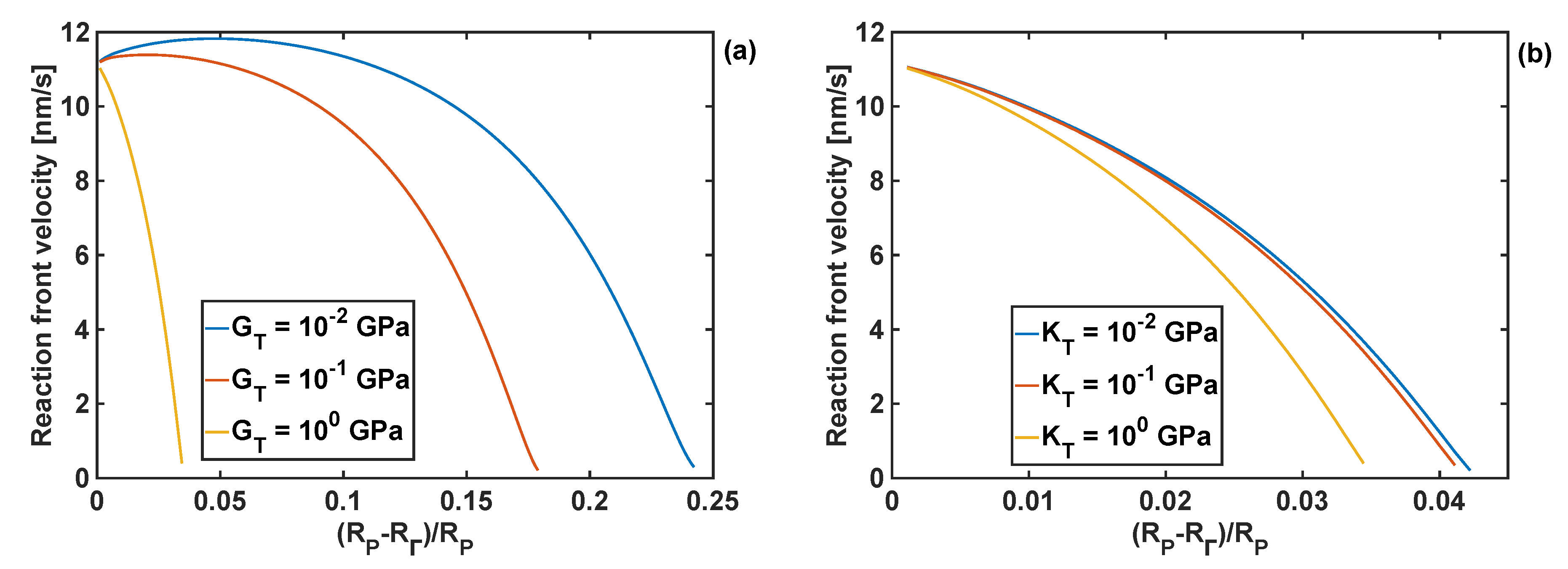
4.3. Effect of Coating Moduli on Reaction Front Velocity

In addition to stresses, a change in bulk and shear moduli of the coating can affect the reaction front velocity and degree of lithiation. Therefore, the effect of different combinations of bulk and shear modulus on the reaction front velocity are shown in Figure 6, where the front starts from the edge of the particle, i.e., at ( R P R Γ ) / R P = 0 , and then it moves towards the particle centre. In the case when the polymer coating is not used, the reaction front increases initially, and it stays almost constant afterwards for a certain period of time, and then rapidly drops to zero. Such a complex velocity profile is the result of an interplay between different components of the configurational driving force, and it is significantly influenced by problem parameters. These dependencies were analysed in detail in [30].
When the coating is applied to the particle, and for a range of shear moduli and the bulk modulus of 1 GPa, the reaction front velocity rises slightly, before stabilising at the velocity of between 13 and 14 nm/s, depending on the coating properties. As the reaction front approaches the particle centre, the reaction front starts slowing down rapidly, until it is eventually arrested at the reaction fron position R Γ = 0.15 R P . This trend in the velocity profile is only slightly affected by the change of the shear modulus of the coating for the given value of the bulk modulus. However, for the same range of shear moduli and the larger bulk modulus of 10 GPa, significant changes in the reaction front velocity profile are found, as shown in Figure 6b. In particular, for larger values of the shear moduli the velocity of the reaction front decreases rapidly after the lithiation process starts. For such combination of moduli, an increase in stresses at the reaction front inhibits the lithiation reaction. This is undesirable from the energy storage point of view, as only a small portion of Si particle domain undergoes lithiation.
It must be noted that due to spherical symmetry, the normalised position of the reaction front R Γ / R P corresponds to the material transformation of 1 ( R Γ / R P ) 3 of material volume fraction. For example, the normalised radial position of the reaction front of 0.5 corresponds to a volumetric transformation of 87.5% of available Si.
The effects of the coating bulk modulus on the reaction front velocity for the given coating thickness and shear moduli of 1 and 10 GPa are shown in Figure 7. Qualitatively, these responses are similar to the effect of the shear modulus of the coating on the front velocity, when the fixed bulk modulus is fixed, as shown in Figure 6.
It should be noted that when the largest value of the bulk modulus of the coating was used, KT =101.5 GPa, the reaction did not start as the constraints from the volumetrically stiff coating generated too large stresses in Si particle for the reaction front to propagate. Irrespectively of the value of the coating shear modulus, the lowest value of the bulk modulus, KT = 0.1 GPa, resulted in similar results for the reaction front velocity as when no coating was present.
In order to generalise the results, a systematic study on the effects of combinations of the coating moduli G T and K T on the degree of lithiation in Si particles was performed, as shown in Figure 8. The degree of lithiation is defined a β = ( R P R Γ ) / R P at the velocity of 2 nm / s . The smallest values of both parameters do not generate sufficiently large stresses to affect the extent of lithiation, and the resulting degree of lithiation is β = 0.82 for G T = 10 1   GPa ,   K T = 10 1   GPa . The degree of lithiation is significantly reduced when the coating parameters are above 1 GPa-in particular, β = 0.29 for G T = 10 1   GPa   and   K T = 10 1   GPa , and β = 0.02   for G T = 10 1.5   GPa ,     and   K T = 10 1.5   GPa .

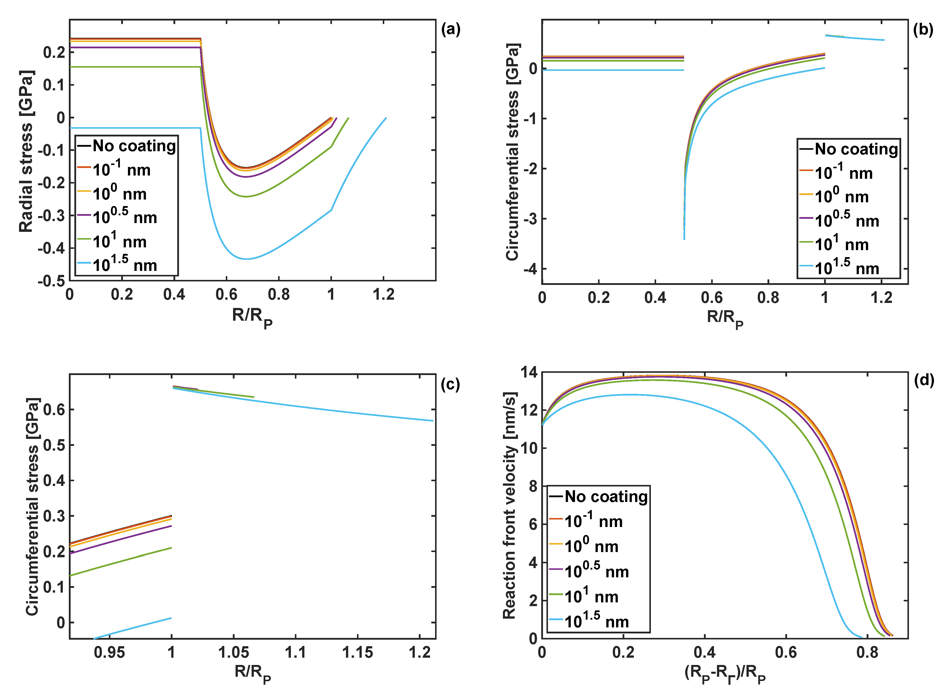
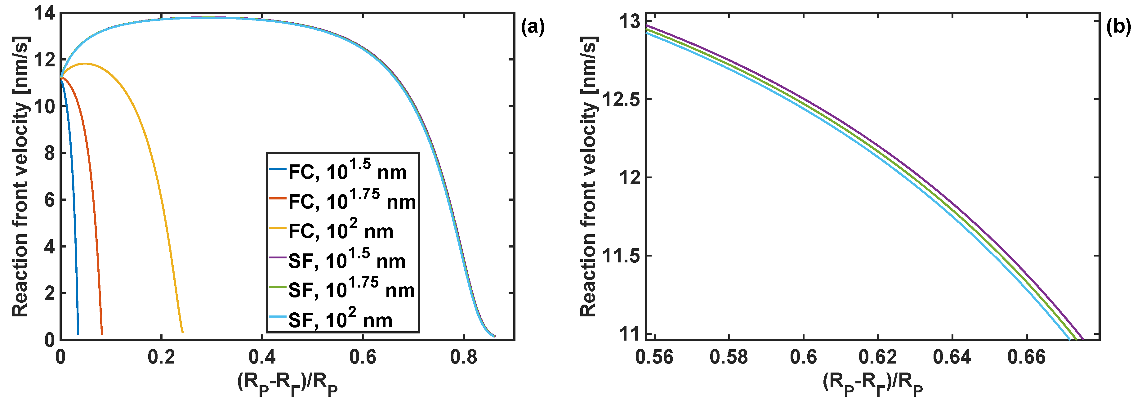
4.4. Effect of Coating Thickness on Stresses and Reaction Front Velocity

It was found that as the coating thickness increases, both the radial and the circumferential stresses are reduced, as shown in Figure 9. However, that reduction in the stress values is relatively small for coating thicknesses up to 10 0.5 nm, and both stress components remain positive in the particle core. More significant changes occur when the coating thickness is 10 nm, and the circumferential stresses at the particle edge are reduced to 0.21 GPa, compared to 0.30 GPa for the uncoated particle.
For the thickest polymer coating studied here, h = 10 1.5   nm , both radial and circumferential stresses are compressive over the entire domain of the particle.
The response of the reaction front velocity to changes in the coating thickness are shown in Figure 9d. Similarly, the velocity response of the coating thickness is only slightly reduced for coating thicknesses up to h = 10 0.5 nm. A more tangible reduction is found for the coating thickness of h = 10 nm and h = 10 1.5 nm, with the latter leading to the reduction of the reaction arrest point by 0.05   R P .

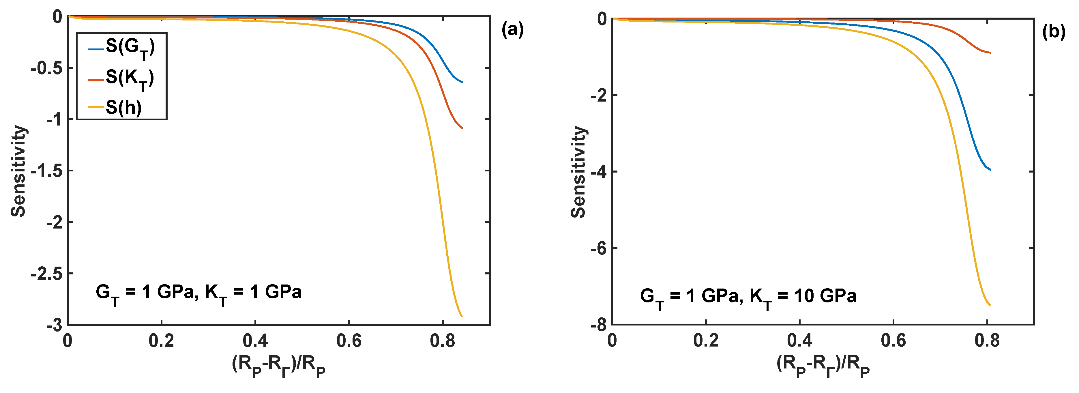
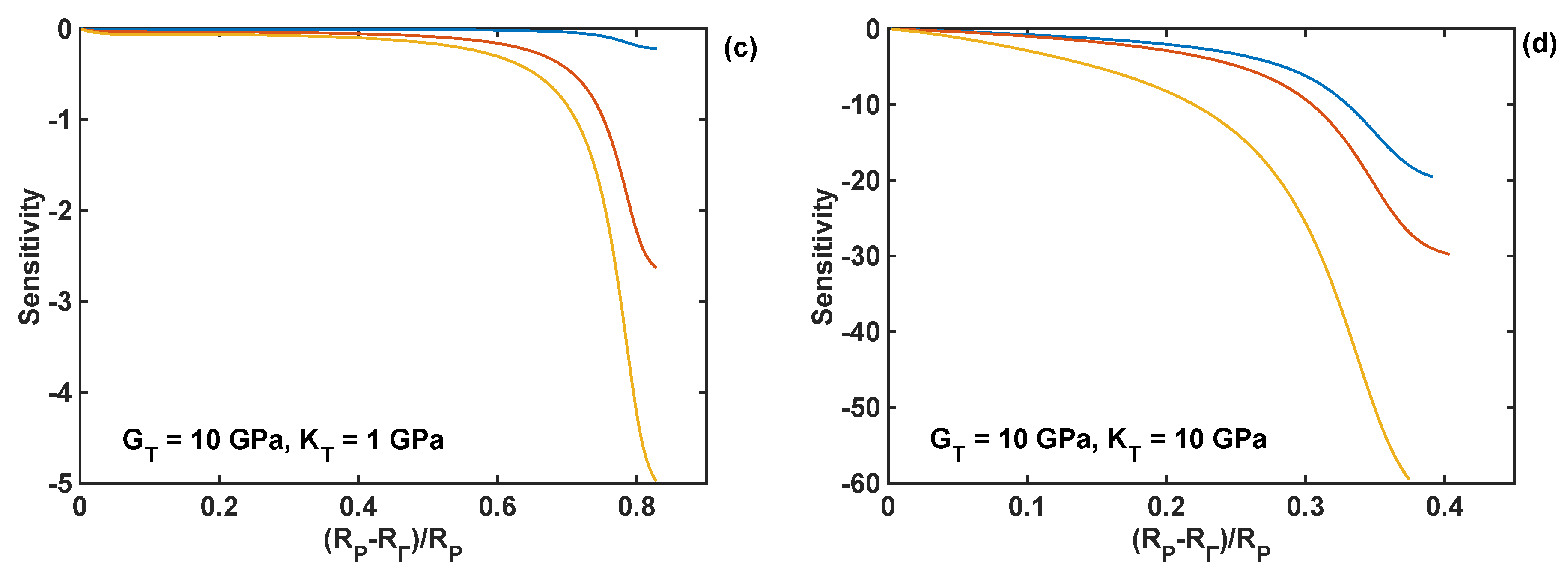
4.5. Sensitivity Analysis of Reaction Front Velocity to Coating Properties

The relative sensitivities [35,36] of the normal component of the reaction front velocity with respect to the design parameters (shear modulus, bulk modulus, and thickness of the coating) were calculated to compare the effect of different coating parameters on the velocity. These sensitivities are defined here as the normalised partial derivatives of the velocity with respect to the design parameter P:
S ( P ) = V P P V ,               V P Δ V Δ P = V ( P + Δ P ) V ( P ) Δ P
where P stands for the design parameters G T , K T or h . These sensitivities were calculated numerically using a small perturbation of 1% of the nominal parameter value.
The relative sensitivities of the reaction front velocity were evaluated for four different combinations of nominal values of the shear and bulk modulus, and they are plotted as different cases in Figure 10 as functions of the normalised position of the reaction front. In particular, all the relative sensitivities were found to be negative through the entire lithiation range, which means that the increase in the coating parameter leads to the decrease in the reaction velocity. The sensitivities are smaller at the edge of the particle (i.e., at R = RP), and their absolute values increase with the movement of the reaction front. The significant increase in sensitivity values is caused by the normalisation used here, which requires division by the velocity—the latter decreases to zero towards the end of lithiation process, as shown in Figure 9d. In Figure 10, it is shown that the coating thickness is the most significant parameter influencing the velocity of the lithiation process in Si particles for all investigated combinations of the moduli.

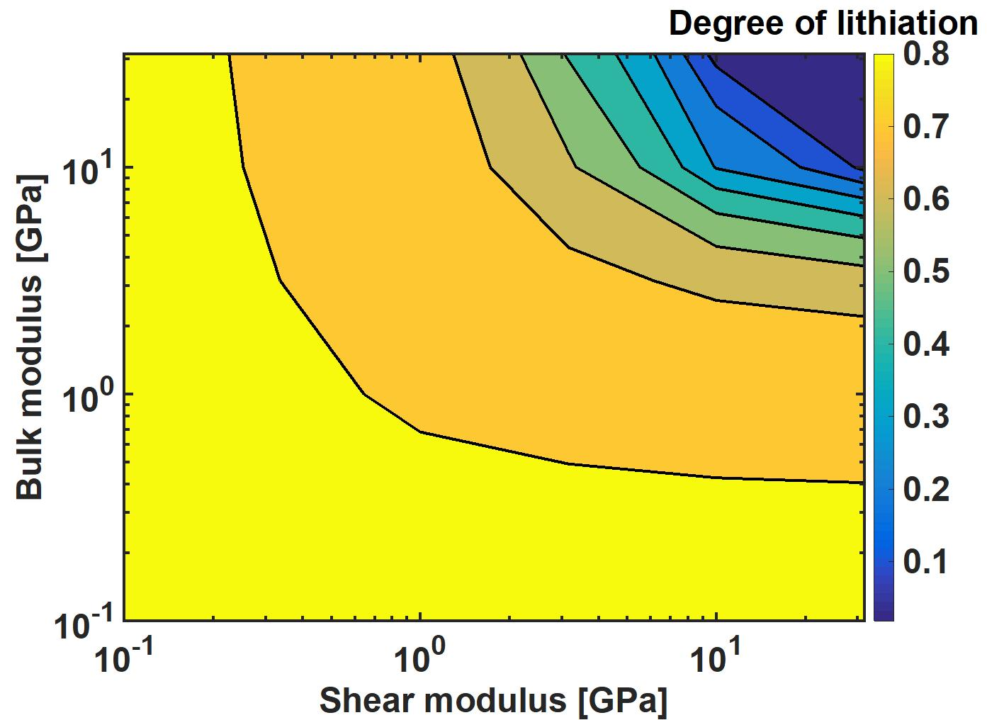
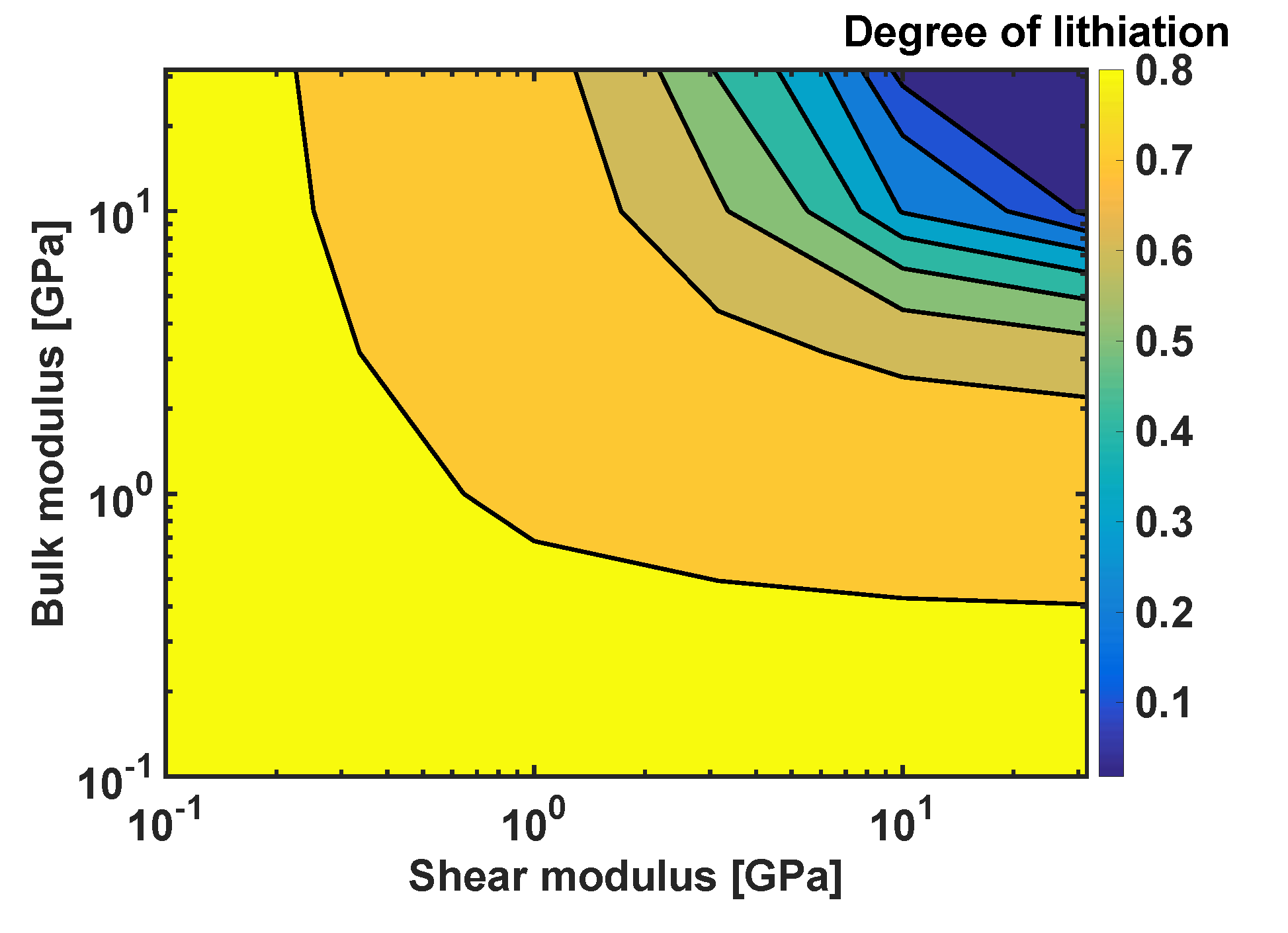
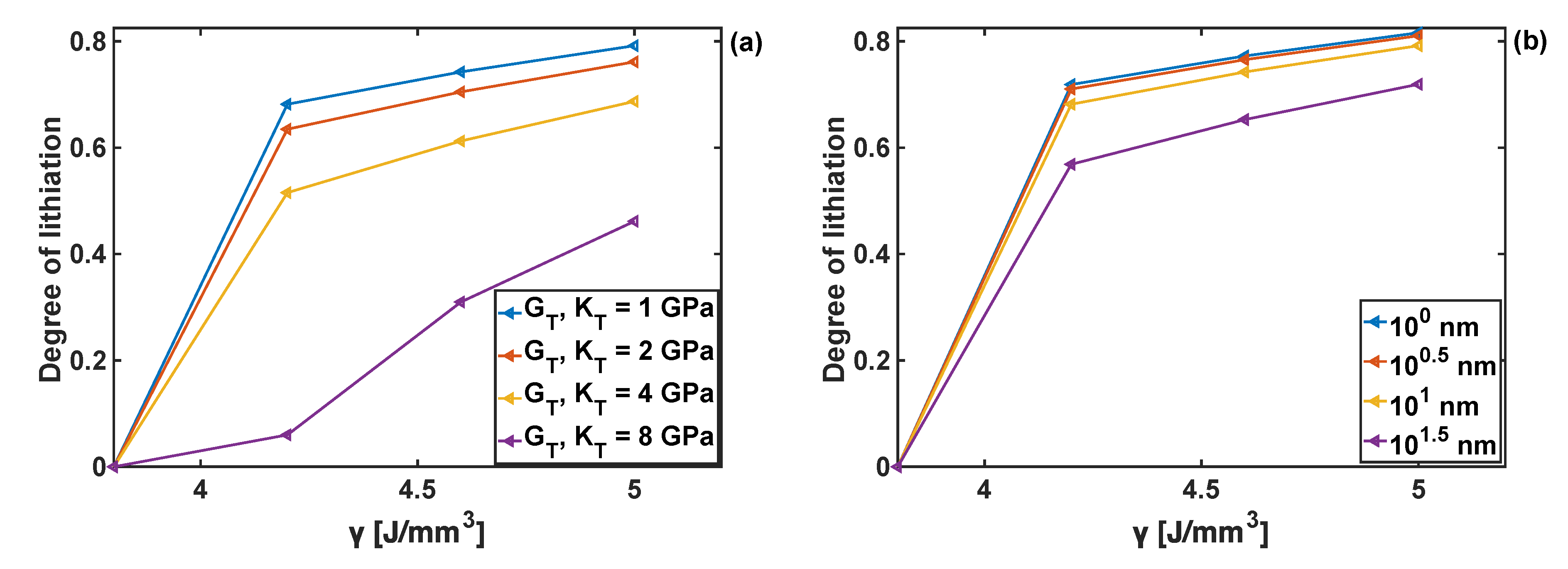
4.6. Combined Effects of Coating Parameters and Chemical Energy

Chemical energy, γ , (cf. Equation (5)), controls the reaction rate in the absence of mechanical stresses. Increase in γ results in an increase of the reaction rate. In the case when mechanical stresses are present in the particle, increase in γ also results in the increase in the degree of lithiation. The detailed analysis of the effect of chemical energy on the lithiation kinetics of the uncoated particle has been reported in [30]. Here the influence of γ on the degree of lithiation is studied for the coated particle. In general, once the value of γ reaches a critically low value the reaction cannot start, as shown in Figure 11, for γ < 4 J/mm3. It was also found that the increase in the bulk and shear moduli of the coating reduces the degree of lithiation for the given value of chemical energy. This results from the fact that the coating parameters lead to changes in stresses within the particle, as discussed in Section 4.2. In turn, those stresses affect the kinetics of the reaction (cf. Equations (4) and (5)), where it can be seen that at low values of γ , the velocity becomes much more sensitive to the stresses, and consequently to the values of coating moduli. Qualitatively, similar trends can be observed when varying the coating thickness (see Figure 11b)—no lithiation is possible below the threshold value of chemical energy parameter γ = 4 J/mm3, and the degree of lithiation is reduced with an increase of coating thickness. The latter results from the constraint effect imposed on the particle (for the particle subject to stress-free boundary conditions), which increases with the increasing thickness of the coating, and thus leading to the increase in stress value that in turn affect the reaction front velocity.

4.7. Effect of Particle Constraints (Non-Stress-Free Boundary Conditions)

Si particles in LIB electrodes are often embedded in a complex composite mixture of binder, graphite particles, pores and electrolyte. The mixture imposes certain mechanical constraints onto Si particles. In this paper, only two extreme cases are considered—a stress-free particle (discussed in the previous sections), and a fully constrained particle, i.e., when the radial component of displacement u R = 0   at   R = R T . The reaction front velocity at different stages of lithiation in a fully-constrained particle and for different combinations of the coating bulk and shear moduli is shown in Figure 12. It is worth mentioning that the coating thickness of hT = 10 2 nm was used in this particular study, as it was found that for a fully constrained particle only a sufficiently thick coating can facilitate the expansion of the particle, while thinner coatings immediately led to the arrest of the reaction (as the coating is subject to radial constraints). As shown in Figure 12a, for the fully constrained particle to achieve a higher degree of lithiation, coatings with lower shear moduli are favored. Moreover, for the given value of coating shear modulus (GT = 1 GPa) and coating thickness (hT = 102 nm), the reaction is blocked at early lithiation stages, between R Γ = 0.035 R P and R Γ = 0.045 R P , for coating bulk moduli from KT = 10−2 to 100 GPa, respectively of the value of the bulk modulus.
The actual effect of the two types of boundary conditions is shown Figure 13, where the reaction front velocity profiles are compared for coating identical bulk and shear moduli and three different coating thicknesses. In particular, it can be seen that the degree of lithiation, described by the extent of the velocity profile, is significantly decreased when the particle is fully constrained (see Figure 13a), as compared to stress-free particles. This implies strong effects of boundary conditions and the material behaviour of the particle-surrounding medium in battery anodes on the degree of particle lithiation. Moreover, it shows the importance of capturing accurately the constitutive behaviour of the material surrounding Si particles for full-scale (3D) finite-element simulations of the problem.

5. Conclusions

A nonlinear chemo-mechanical model and associated finite-element study for a spherical elasto-viscoplastic Si particle with a hyperelastic coating are reported in this paper. For this, previously developed finite-strain nonlinear chemo-mechanical model, coupling stress, diffusion, and reaction front velocity for an uncoated Si particle, are extended here to account for the effects of the design parameters of a hyperelastic coating (shear modulus, bulk modulus, coating thickness) on stress components, velocity of a non-stationary lithiation reaction front, and degree of lithiation. The model equations are solved numerically using the finite-element method taking advantage of the spherical symmetry of the problem.
In general, the largest influence was obtained when values of the shear and bulk moduli of the coating are above 101 GPa, which led to an increase of the absolute values of the radial and circumferential stress components in the particle. Due to the stress-diffusion–velocity coupling, the increase in stresses reduced the velocity of the reaction front, and also the degree of lithiation. A simple deterministic sensitivity analysis of the reaction front velocity with respect to coating parameters showed that the coating thickness is the most influential design parameter that affects the velocity of the reaction front.
From the materials design viewpoint, the results from this study suggest that the risk of Si particle fracture at its external surface due to tensile circumferential stresses can be minimised by increasing both moduli and thickness of the coating. However, this study also predicts that an increase in those coating parameters can arrest the reaction front movement, and thus it can reduce the extent of lithiation. As the latter, in turn, can prevent the battery from efficient charging, a careful optimisation of the polymer coating properties for the given electrochemical conditions (cell current/voltage, electrolyte, etc.) of a Li-ion battery with silicon-based anodes is required.

Author Contributions

Conceptualization, Ł.F. and M.P.; Methodology, Ł.F. and M.P; Software, M.P. and P.L.; Formal Analysis, P.L., M.P. and Ł.F.; Investigation, P.L., M.P. and Ł.F.; Writing-Original Draft Preparation, P.L.; Writing-Review & Editing, M.P. and Ł.F; Visualization, P.L.; Supervision, Ł.F. and M.P.; Project Administration, Ł.F.; Funding Acquisition, Ł.F.

Funding

Financial support from the EU Horizon 2020 framework through the project “SINTBAT” (685716), and a studentship from the Energy GRP (University of Warwick), are gratefully acknowledged.

Conflicts of Interest

The authors declare no conflict of interest.

Appendix A

Table A1. Used parameters and their values of a two-phase Si particle.
ParameterValueParameterValueParameterValueParameterValue
K + [ GPa ]28.5 ρ [ g c m 3 ]2.285 M [ g m o l ]28.0855 n + [None]1/15
G h [ GPa ]0.5 q [None]24 T [ K ]293.15 γ [ J m m 3 ]5
D [ m 2 s ] 10 12 α [ n m s ]2000 g [None]41/3 E [ GPa ]80
τ 0 [ n s ]2 c [ m o l c m 3 ]0.053 n [None]4/15 v [None]0.22
σ 0 [ GPa ]1 k [ n m s ]86 n [None]1 E + [ GPa ]41

References

  1. Tarascon, J.-M.; Armand, M. Issues and challenges facing rechargeable lithium batteries. Nature 2001, 414, 359–367. [Google Scholar] [CrossRef]
  2. Goodenough, J.B.; Kim, Y. Challenges for rechargeable li batteries. Chem. Mater. 2009, 22, 587–603. [Google Scholar] [CrossRef]
  3. Ma, D.; Cao, Z.; Hu, A. Si-based anode materials for Li-ion batteries: A mini review. Nano-Micro Lett. 2014, 6, 347–358. [Google Scholar] [CrossRef]
  4. McDowell, M.T.; Lee, S.W.; Nix, W.D.; Cui, Y. 25th anniversary article: Understanding the lithiation of silicon and other alloying anodes for lithium-ion batteries. Adv. Mater. 2013, 25, 4966–4985. [Google Scholar] [CrossRef]
  5. Endo, M.; Kim, C.; Nishimura, K.; Fujino, T.; Miyashita, K. Recent developments of carbon materials for Li ion batteries. Carbon 2000, 38, 183–197. [Google Scholar] [CrossRef]
  6. Wu, C.Y.; Chang, C.C.; Duh, J.G. Silicon nitride coated silicon thin film on three dimensions current collector for lithium ion battery anode. J. Power Sources 2016, 325, 64–70. [Google Scholar] [CrossRef]
  7. Boukamp, B.A.; Lesh, G.C.; Huggins, R.A. All-solid lithium electrodes with mixed-conductor matrix. J. Electrochem. Soc. 1981, 128, 725–729. [Google Scholar] [CrossRef]
  8. Beaulieu, L.Y.; Eberman, K.W.; Turner, R.L.; Krause, L.J.; Dahn, J.R. Colossal reversible volume changes in lithium alloys. Electrochem. Solid-State Lett. 2001, 4, A137–A140. [Google Scholar] [CrossRef]
  9. Nitta, N.; Wu, F.; Lee, J.T.; Yushin, G. Li-ion battery materials: Present and future. Mater. Today 2015, 18, 252–264. [Google Scholar] [CrossRef]
  10. Van Havenbergh, K.; Turner, S.; Marx, N.; Van Tendeloo, G. The mechanical behavior during (De)lithiation of coated silicon nanoparticles as anode material for lithium-ion batteries studied by in situ transmission electron microscopy. Energy Technol. 2016, 4, 1005–1012. [Google Scholar] [CrossRef]
  11. McDowell, M.T.; Ryu, I.; Lee, S.W.; Wang, C.; Nix, W.D.; Cui, Y. Studying the kinetics of crystalline silicon nanoparticle lithiation with in situ transmission electron microscopy. Adv. Mater. 2012, 24, 6034–6041. [Google Scholar] [CrossRef]
  12. Zhang, W.J. A review of the electrochemical performance of alloy anodes for lithium-ion batteries. J. Power Sources 2011, 196, 13–24. [Google Scholar] [CrossRef]
  13. Wu, H.; Cui, Y. Designing nanostructured Si anodes for high energy lithium ion batteries. Nano Today 2012, 7, 414–429. [Google Scholar] [CrossRef]
  14. Yao, Y.; McDowell, M.T.; Ryu, I.; Wu, H.; Liu, N.; Hu, L.; Nix, W.D.; Cui, Y. Interconnected silicon hollow nanospheres for lithium-ion battery anodes with long cycle life. Nano Lett. 2011, 11, 2949–2954. [Google Scholar] [CrossRef]
  15. Liu, N.; Lu, Z.; Zhao, J.; McDowell, M.T.; Lee, H.W.; Zhao, W.; Cui, Y. A pomegranate-inspired nanoscale design for large-volume-change lithium battery anodes. Nat. Nanotechnol. 2014, 9, 187–192. [Google Scholar] [CrossRef] [Green Version]
  16. Yen, Y.C.; Chao, S.C.; Wu, H.C.; Wu, N.L. Study on solid-electrolyte-interphase of Si and C-coated Si electrodes in lithium cells. J. Electrochem. Soc. 2009, 156, A95–A102. [Google Scholar] [CrossRef]
  17. Liu, B.; Soares, P.; Checkles, C.; Zhao, Y.; Yu, G. Three-dimensional hierarchical ternary nanostructures for high-performance Li-ion battery anodes. Nano Letters 2013, 13, 3414–3419. [Google Scholar] [CrossRef]
  18. Wu, H.; Yu, G.; Pan, L.; Liu, N.; McDowell, M.T.; Bao, Z.; Cui, Y. Stable Li-ion battery anodes by in-situ polymerization of conducting hydrogel to conformally coat silicon nanoparticles. Nat. Commun. 2013, 4, 1943. [Google Scholar] [CrossRef] [Green Version]
  19. Luo, L.; Zhao, P.; Yang, H.; Liu, B.; Zhang, J.G.; Cui, Y.; Yu, G.; Zhang, S.; Wang, C.M. Surface coating constraint induced self-discharging of silicon nanoparticles as anodes for lithium ion batteries. Nano Lett. 2015, 15, 7016–7022. [Google Scholar] [CrossRef]
  20. Gao, P.; Fu, J.; Yang, J.; Lv, R.; Wang, J.; Nuli, Y.; Tang, X. Microporous carbon coated silicon core/shell nanocomposite via in situ polymerization for advanced Li-ion battery anode material. Phys. Chem. Chem. Phys. 2009, 11, 11101–11105. [Google Scholar] [CrossRef]
  21. Levitas, V.I.; Attariani, H. Anisotropic compositional expansion in elastoplastic materials and corresponding chemical potential: Large-strain formulation and application to amorphous lithiated silicon. J. Mech. Phys. Solids 2014, 69, 84–111. [Google Scholar] [CrossRef]
  22. Loeffel, K.; Anand, L. A chemo-thermo-mechanically coupled theory for elastic–viscoplastic deformation, diffusion, and volumetric swelling due to a chemical reaction. Int. J. Plast. 2011, 27, 1409–1431. [Google Scholar] [CrossRef]
  23. Jia, Z.; Li, T. Stress-modulated driving force for lithiation reaction in hollow nano-anodes. J. Power Sources 2015, 275, 866–876. [Google Scholar] [CrossRef]
  24. Freidin, A.B.; Vilchevskaya, E.N.; Korolev, I.K. Stress-assist chemical reactions front propagation in deformable solids. Int. J. Eng. Sci. 2014, 83, 57–75. [Google Scholar] [CrossRef] [Green Version]
  25. He, Y.; Piper, D.M.; Gu, M.; Travis, J.J.; George, S.M.; Lee, S.H.; Genc, A.; Pullan, L.; Liu, J.; Mao, S.X.; et al. In situ transmission electron microscopy probing of native oxide and artificial layers on silicon nanoparticles for lithium ion batteries. ACS Nano 2014, 8, 11816–11823. [Google Scholar] [CrossRef]
  26. Li, W.; Wang, Q.; Cao, K.; Tang, J.; Wang, H.; Zhou, L.; Yao, H. Mechanics-based optimization of yolk-shell carbon-coated silicon nanoparticle as electrode materials for high-capacity lithium ion battery. Compos. Commun. 2016, 1, 1–5. [Google Scholar] [CrossRef]
  27. Wang, J.W.; He, Y.; Fan, F.; Liu, X.H.; Xia, S.; Liu, Y.; Harris, C.; Li, H.; Huang, J.; Mao, S.; et al. Two-phase electrochemical lithiation in amorphous silicon. Nano Lett. 2013, 13, 709–715. [Google Scholar] [CrossRef]
  28. Liu, X.H.; Wang, J.W.; Huang, S.; Fan, F.; Huang, X.; Liu, Y.; Krylyuk, S.; Yoo, J.; Dayeh, A.V.; Mao, S.X.; et al. In situ atomic-scale imaging of electrochemical lithiation in silicon. Nat. Nanotechnol. 2012, 7, 749–756. [Google Scholar] [CrossRef]
  29. Li, W.; Cao, K.; Wang, H.; Liu, J.; Zhou, L.; Yao, H. Carbon coating may expedite the fracture of carbon-coated silicon core–shell nanoparticles during lithiation. Nanoscale 2016, 8, 5254–5259. [Google Scholar] [CrossRef]
  30. Poluektov, M.; Freidin, A.B.; Figiel, Ł. Modelling stress-affected chemical reactions in non-linear viscoelastic solids with application to lithiation reaction in spherical Si particles. Int. J. Eng. Sci. 2018, 128, 44–62. [Google Scholar] [CrossRef]
  31. Bower, A.F.; Guduru, P.R.; Chason, E. Analytical solutions for composition and stress in spherical elastic–plastic lithium-ion electrode particles containing a propagating phase boundary. Int. J. Solids Struct. 2015, 69, 328–342. [Google Scholar] [CrossRef] [Green Version]
  32. Freidin, A.B. On the chemical affinity tensor for chemical reactions in deformable materials. Mech. Solids 2015, 50, 260–285. [Google Scholar] [CrossRef]
  33. Freidin, A.B. Chemical affinity tensor and stress-assist chemical reactions front propagation in solids. In Proceedings of the ASME 2013 International Mechanical Engineering Congress and Exposition, San Diego, CA, USA, 15–21 November 2013; The American Society of Mechanical Engineers: New York, NY, USA, 2013. IMECE2013-64957. [Google Scholar]
  34. Liu, N.; Wu, H.; McDowell, M.T.; Yao, Y.; Wang, C.; Cui, Y. A yolk-shell design for stabilized and scalable Li-ion battery alloy anodes. Nano Lett. 2012, 12, 3315–3321. [Google Scholar] [CrossRef]
  35. Frank, P.M. Introduction to System Sensitivity Theory; Academic Press: New York, NY, USA, 1978. [Google Scholar]
  36. Figiel, Ł.; Kamiński, M. Numerical probabilistic approach to sensitivity analysis in a fatigue delamination problem of a two layer composite. Appl. Math. Comput. 2009, 209, 75–90. [Google Scholar] [CrossRef]
Figure 1. Spherical polymer-coated Si particle undergoing a two-phase lithiation process (the lithiated particle is shown as mapped onto the reference (undeformed) configuration); coating thickness h = R T R P ; R Γ denotes the position of the reaction front mapped onto the reference (undeformed) configuration.
Coatings 08 00455 g001
Figure 2. Schematic representation of the FE mesh and the reaction front movement from the edge (RN) of the particle to its centre (R0).
Coatings 08 00455 g002
Figure 3. (a) Radial stress component as a function of normalised particle radius for different shear moduli of the coating, and h = 10 nm and KT = 1 GPa. (b) Zoom-in on the radial stresses close to the edge of the particle and within the coating.
Coatings 08 00455 g003
Figure 4. (a) Circumferential stress component as a function of normalised particle radius for different shear moduli, and h = 10 nm and KT = 1 GPa. (b) Zoom-in on the circumferential stresses close to the edge of the particle and within the coating.
Coatings 08 00455 g004
Figure 5. Circumferential stresses and pressure as functions of the reaction front position for different combinations of the coating moduli: (a) circumferential component; (b) pressure; h = 10 nm.
Coatings 08 00455 g005
Figure 6. Profiles of reaction front velocity for different coating shear moduli. (a) KT = 1 GPa and h = 10 nm. (b) KT = 10 GPa and h = 10 nm thickness.
Coatings 08 00455 g006
Figure 7. Profiles of reaction front velocity for different coating bulk moduli. (a) GT = 1 GPa, h = 10 nm. (b) GT = 10 GPa and h = 10 nm.
Coatings 08 00455 g007
Figure 8. Degree of lithiation as a function of the bulk modulus and shear modulus; h = 10 nm.
Coatings 08 00455 g008
Figure 9. Stresses for different coating thicknesses h = 10−1 ÷ 101.5 nm, and GT = KT = 1 GPa; (a) radial stresses; (b) zoom-on of radial stresses; (c) circumferential stresses; (d) reaction front velocity.
Coatings 08 00455 g009
Figure 10. Sensitivity profiles of the reaction front velocity with respect to shear modulus (GT), bulk modulus (KT), and thickness (hT) of the coating for different combinations of shear and bulk moduli; nominal coating thickness of 10 nm is used in all simulations. (a) GT = KT =1 GPa; (b) GT = 1 GPa, KT = 10 GPa; (c) GT = 10 GPa, KT = 1 GPa; (d) GT = KT = 10 GPa.
Coatings 08 00455 g010aCoatings 08 00455 g010b
Figure 11. Degree of lithiation achieved as a function of the chemical energy parameter γ; (a) effect of coating moduli GT and KT when coating thickness hT =10 nm. (b) Effect of hT when GT = KT = 1 GPa.
Coatings 08 00455 g011
Figure 12. Reaction front velocity profiles of the fully-constrained particle. (a) For different coating shear moduli and coating bulk modulus KT = 1 GPa and thickness of hT = 102 nm; (b) For different coating bulk moduli and coating shear modulus GT = 1 GPa and hT = 102 nm.
Coatings 08 00455 g012
Figure 13. Reaction front velocity profiles for particles with different coating thicknesses and subject to different boundary conditions (fully-constrained (FC) and stress-free (SF)); coating shear modulus of 10−2 GPa and bulk modulus of 100 GPa; (a) full range; (b) limited range—zoomed-in velocity profiles for SF boundary conditions.
Coatings 08 00455 g013

