1. Introduction
High Friction Surfacing (HFS) is a specialist, high performance road surface material that is applied as a thin coating. HFS is used at road locations where there is a high risk of accidents that may result in serious injury or death. It has been used in the United Kingdom (UK) since the early 1960s. HFS is now specified in the UK as a proprietary system with a performance guarantee. A considerable amount of laboratory and full-scale roads trials was done in its early development resulting in understanding of material requirements and methods of prediction.
The aim of this paper is to inform, i.e., those who already have experience with HFS, those who are new to HFS and those who may be thinking of using HFS for the first time to reduce accidents that result in serious injury or death. This paper considers how the in-service performance of HFS may be predicted in the laboratory. HFS is a high-performance road surface material and predicting how it performs is therefore critical as incorrect prediction may result in unexpected road accidents, serious injury or loss of life. Laboratory testing must be severe and be able to highlight problems associated with in-service use.
There are two basic types of HFS. Cold applied consists of layer of 2–4 mm sized aggregate particles bonded to the existing road surface using a resin binder. Hot applied is a resin and aggregate mixture that is heated at high temperature and screeded onto the road surface in strips.
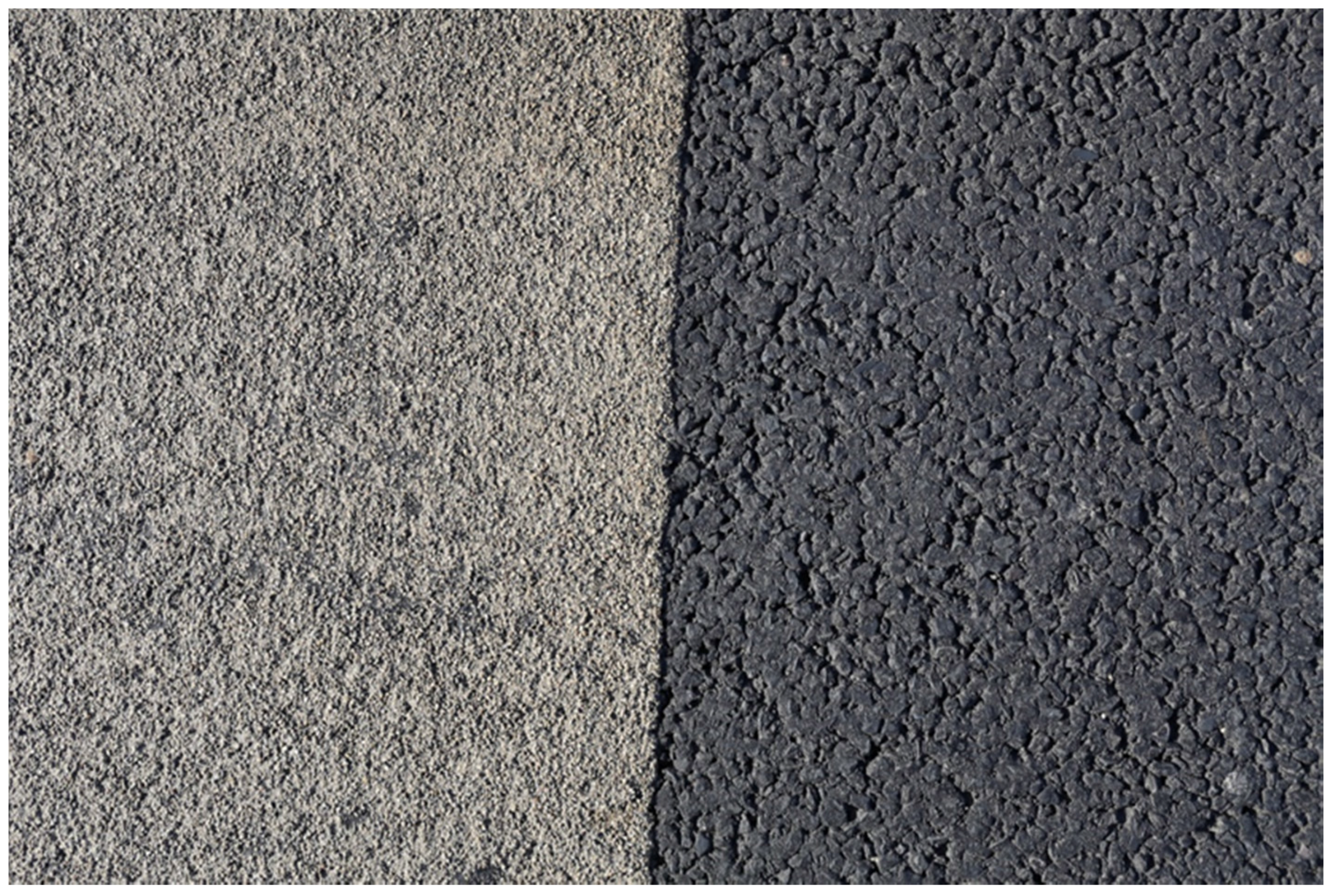
Figure 1 shows a hot HFS coating applied to a 10 mm Thin Surface Course System (TSCS). The HFS has been subjected to approximately 1 year of trafficking.
Both types of HFS create a harsh surface texture. The small size aggregate particles give the tyre/HFS interface a concentrated distribution of very high contact pressures. The selection of aggregate is critical to ensure long life. The aggregate particles must be extremely hard wearing to maintain their sharp edges and so bite into the tyre rubber. They must not become rounded, wear away or shear-off under the stress of turning and braking tyres.
The first road trial in the UK to highlight the exceptional performance of HFS was in the 1959 [
1]. This found a cold applied HFS using refractory grade calcined bauxite as a 3 mm aggregate to out-perform a range of different natural aggregates. Road trials in London in the mid-1960s found a 52% reduction in total accidents in the first year after it was used to treat high risk sites [
2,
3].
These initial HFS laboratory investigations and road trials in the UK found refractory grade calcined bauxite to perform the best in terms of skid and wear resistance. In the subsequent 50 years since the first trials, no naturally occurring aggregate quarried from the ground has been found to give a level of in-service performance matching that of refractory grade calcined bauxite. Some types of natural aggregate have very good skid resistance but suffer poor resistance to wear. Natural aggregate with very good resistance to wear will polish and become slippery [
4].
In recent years, there has been a significant increase in the use of HFS around the world as more countries see its benefit in reducing serious and fatal accidents. With increased use, comes increased demand for aggregates to use in this specialist type of road surfacing. Sourcing a suitable HFS calcined bauxite aggregate has become a problem. Calcined bauxite comes from countries including Guyana, China and more recently India. There are no sources in Europe for example.
All of the research and experience with HFS in the UK shows the highest levels of performance over the longest time periods are only possible with calcined bauxite. However, if a HFS with long-life is not possible due to trafficking and/or environmental conditions, then a HFS that only needs to last 1 or 2 years becomes an option. This creates the possibility of using alternative aggregate types that may offer shorter-term performance rather than long life performance. The amount of calcined bauxite could be reduced by blending or treatment restricted to just the wheel-paths.
This is the purpose of this paper, i.e., to inform how these options may be predicted in the laboratory. It first reviews the development of HFS in the UK to illustrate why aggregate selection is so important. The current use of HFS in the UK is considered to illustrate the importance of specifying HFS with a performance guarantee. This involves an extensive laboratory and road trial accreditation process. Key to this is the Wear test—a laboratory method that predicts performance by subjecting test specimens to extreme simulated trafficking conditions. The paper includes examples illustrating what levels of performance are to be expected with different types of HFS and aggregates.
2. Materials and Methods
The development of HFS in the UK involved many laboratory investigations and full-scale road trials. The majority was done by the Road Research Laboratory (RRL, Crowthrone, UK) and Transport Road Research Laboratory (TRRL, Crowthorne, UK), now known the Transport Research Laboratory (TRL, Crowthorne, UK). This work essentially considered what was the best type of aggregate and binder to ensure the highest possible value of wet skid resistance and wear under the most extreme traffic stressing conditions.
Epoxy-resin was first used in road work in 1954 as adhesives for sticking reflective markers to concrete [
5]. This led to their use mixed with sand in heavy duty screeds for factories. Co-operative research between the RRL and the epoxy-resin producers began in 1958 to investigate possible road applications. One of the areas considered was thin coatings for asphalt or concrete surfacings which had become slippery but otherwise sound.
The first trial in the UK to use epoxy-resin as an alternative to conventional bitumen was the Colnbrook By-Pass in 1959 [
1]. The resins considered had a smooth glassy surface that offered almost no wet skid resistance. They required a dressing of aggregate to give skid resistance. Twelve types of aggregate were selected to be as polish resistant as possible. They included sources of both naturally occurring aggregate and artificial abrasives. As the resin was applied to the road surface as a thin layer the aggregate had to be applied as a small grit of nominal size up to 3 mm.
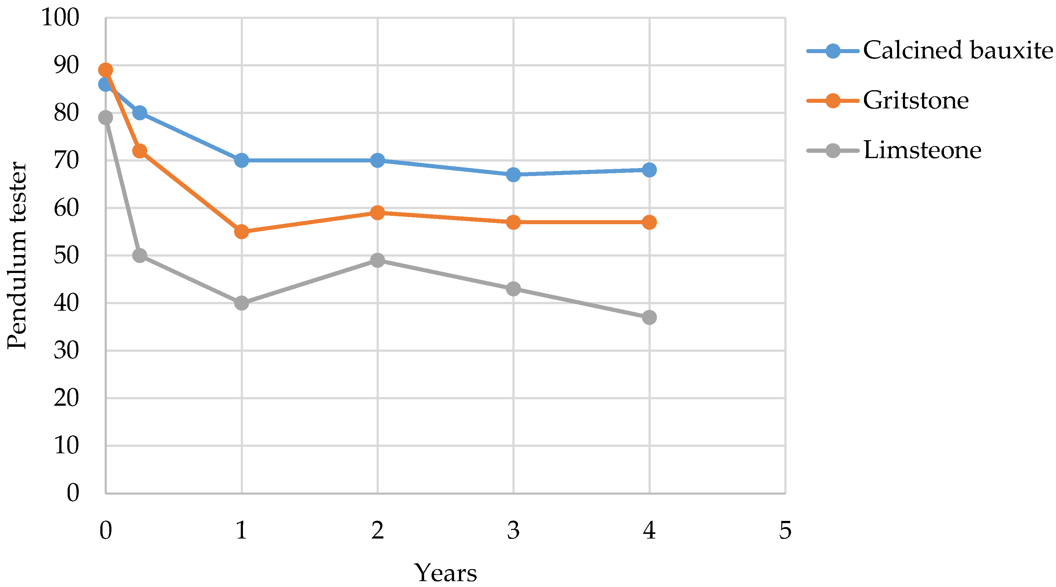
Figure 2 shows the change in skid resistance measured in a wet condition over a 4-year period for the 1959 Colnbrook By-Pass road trial.
Wet skid resistance was measured using a pendulum tester. A refractory grade calcined bauxite from Guyana was found to have the best resistance to polishing. This was found to be higher than all the natural aggregates used especially towards the end of the 4-year trial period as many of the aggregates became polished and lost wet skid resistance. This is shown in
Figure 2. The best natural aggregate was a gritstone. The poorest natural aggregate was a limestone. The pendulum tester data for the other natural aggregates was between these two plots. The data shows that the wet skid resistance of the calcined bauxite was maintained for a much longer period compared to the best natural aggregates which had a limited period of effectiveness.
The A30 Blackbushe trial in 1962 compared aggregate in chip-seal and hot rolled asphalt road surfacings. This was monitored using a sideways force friction measuring device at 30 mph and found calcined bauxite to have much higher values of wet skid resistance [
1]. Bridge-decks including Tower Bridge in London were treated with 3 and 4 mm calcined bauxite during 1960–1962.
Despite growing evidence of high skid resistance being measured for all sites, the high price of calcined bauxite aggregate discouraged people from its use. The turning point occurred with the publicity gained by trials carried out by the Greater London Council [
2,
3]. This found a 52% reduction in total accidents, 51% reduction in the number of causalities, 67% reduction in the number of accidents on wet roads, 45% reduction in the number of accidents on dry road surfaces and a 78% reduction in accidents in which skidding was recorded as a factor. A cost-benefit analysis of capital expenditure (area surfaced, cost of surfacing) to cost return (number of accidents saved, assumed cost per injury accident, anticipated effective life) justified the expense in treating the highest risk sites.
Typical sites identified for treatment were those locations were accidents tended to happen, i.e., the approach to signal controlled junctions, roundabouts and traffic lights subject to a heavy flow of traffic. Prior to treatment with HFS, 70% of reported personal injury accidents had occurred within 20 yards of road junctions. The Sunday Times news-paper reported treatment of these short sites as having a spectacular decrease in car accidents with the success of the anti-skid junctions as being outstanding [
6].
Hosking and Tubey [
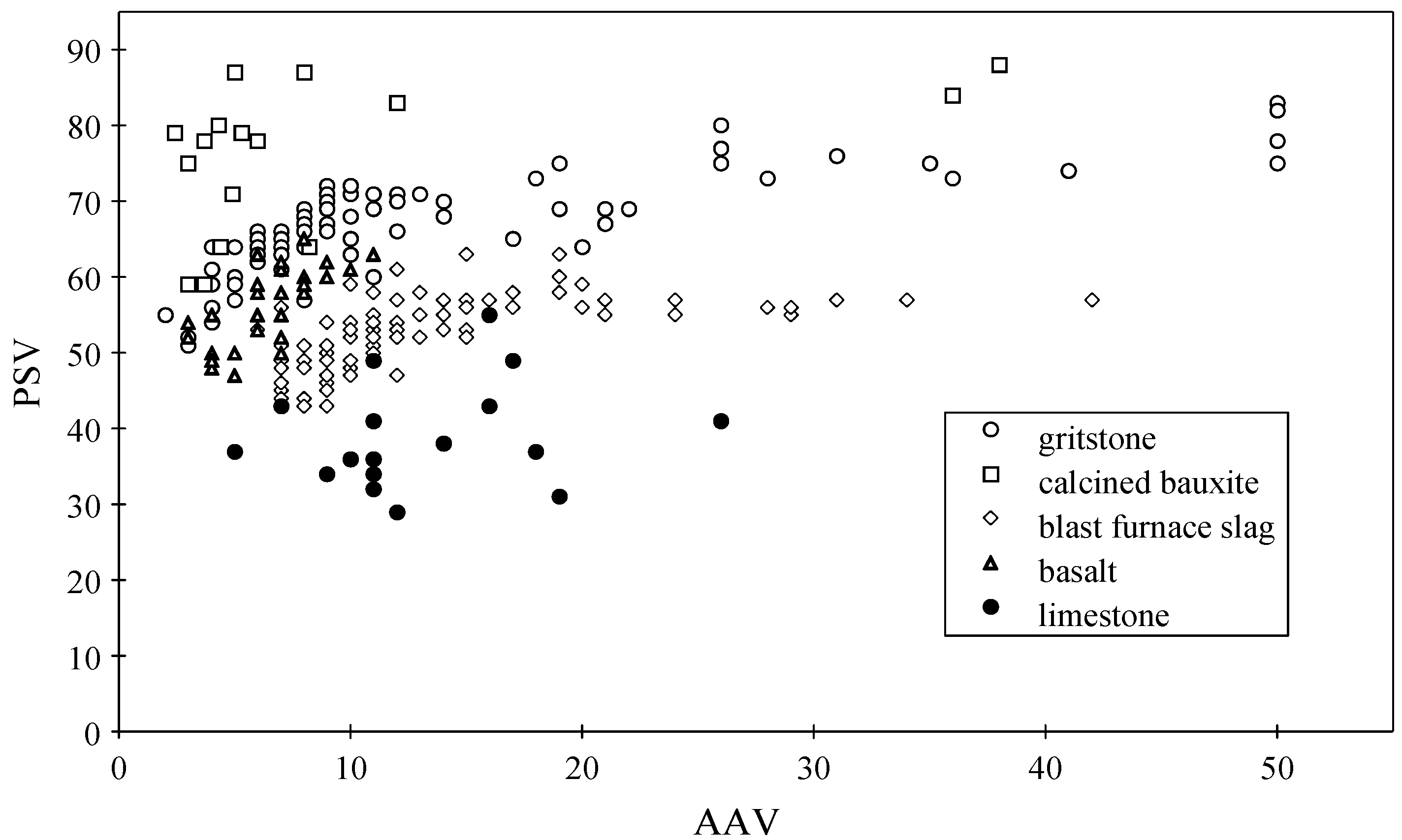
7] compared road performance and laboratory measured parameters. They recommended that aggregates for HFS should have a minimum Polished Stone Value (PSV) of 70 and a maximum Aggregate Abrasion Value (AAV) of 5. This combination of properties is rare for natural aggregates.
Figure 3 plots PSV and AAV data extracted from different RRL and TRRL reports published in the 1960s and 1970s [
4]. This illustrates that only calcined bauxite offers both skid (PSV) and wear (AAV) properties. Hawkes and Hosking [
8] found no natural aggregates that met both the skidding and abrasion requirements. This initiated a sustained programme of research looking at aggregate skid resistance. Assessment of different calcined bauxites found alternative sources and chemical compositions of calcined bauxite were not as effective as the refractory grade from Guyana [
9,
10,
11].
James [
9] proposed five theoretical models or idealised types of aggregate (i) extremely hard minerals, (ii) conglomerates of small hard particles, (iii) dispersions of hard particles in a softer matrix, (iv) vesicular materials and (v) materials which fracture in an irregular manner. Research considered making synthetic alternatives based on these idealised types of aggregate which optimise both PSV and AAV whilst still being cheap and easy to manufacture. Each of these idealised types of aggregate were investigated. Hosking [
12] investigated synthetic gritty aggregates. Tubey and Hosking [
11] investigated corundum rich synthetic aggregates. Tubey and Hosking [
13] investigated porous synthetic aggregates. Hosking and Jacobs [
14] investigated specially shaped chippings.
This period of research in the 1960s and 1970s resulted in much new knowledge in relation to HFS and the aggregates required to ensure its longer life performance. Whilst these numerous studies allowed better understanding of HFS aggregates and their properties no comparable alternative to the original refractory grade calcined bauxite from Guyana was found.
This issue has been a concern ever since the first road trials in 1959 to the current increasing demand for specialist HFS aggregates. It is important that this early research does not become forgotten. The laboratory and on-site methods used 50 years ago are still being used today in the UK and Europe. The PSV and AAV test methods are European Standards used in every European country [
15]. The pendulum device used to measure the HFS laid in the 1959 Colnbrook By-pass road trial is a European Standard [
16] and widely used around the world. Even though this research is over 40 years old it is still relevant and comparable with current HFS laboratory or road trial investigations.
Current researchers are still asking the basic question raised in the early 1960s and 1970s—are there types of aggregate other than calcined bauxite that can be used in HFS? All the previous work in the UK says no. Therefore, this prompts further questions such as can calcined bauxite be used in different ways, for example as a blend with a natural aggregate? If so, what level of in-service performance would be expected? Can natural aggregates be used as a short-term HFS treatment, for example in the wheel paths of heavily trafficked roads. If used in these ways, how long would the HFS provide acceptable skid resistance?
These questions form the basis of the remainder of this paper. It takes what has been learnt in the UK over the last 50 years and illustrates how the use of HFS coatings may be increased in a wider range of applications with differing expectations for in-service performance.
The use of HFS is considered essential in many UK locations to keep the road surface adequately safe for road users.
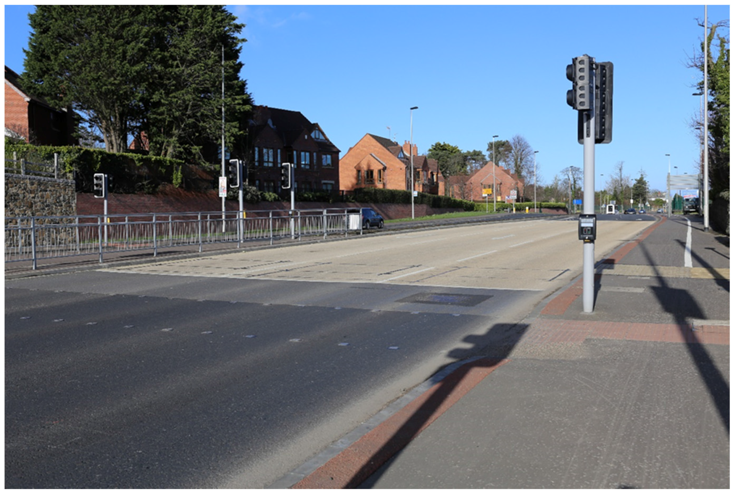
Figure 4 shows a typical HFS site in the UK. This shows a hot applied HFS laid in the approach to a pedestrian crossing controlled by traffic lights. There are two main categories of HFS used in the UK—cold applied and hot applied. The cold applied HFS comprises a resin binder which acts as an adhesive for the aggregate which is typically 1 to 3 mm in size. The resins include epoxy, polyurethane and methyl methacrylate. The resin is installed as a continuous film of adhesive onto which the aggregate is applied. After curing excess aggregate is removed by sweeping. In hot applied HFS, the pre-mixed resin and aggregate is heated in a truck mounted boiler at high temperature and then screeded out in strips.
All types of HFS used in the UK must comply with the Specification for Highway Works Clause 924 [
17]. This requires the HFS to have a current British Board of Agrément HAPAS Roads and Bridges Certificate [
18]. The BBA HAPAS scheme involves meeting demanding performance criteria which are stated on the systems certificate. Clause 924 is an end performance specification that transfers responsibility to the installer and asks for a minimum guarantee of 2 years.
The UK Road Surface Treatments Association have a Code of Practise for High Friction Surfacing [
19]. This states that a HFS installed in full compliance with their code of practise should be able to provide a 5-year guarantee. The performance criteria for a 5-year guarantee asks a skid resistance value ≥65 and a mean texture depth value of ≥1.0. HFS is classified as being either Type 1, Type 2 or Type 3. Type designation relates to the number of commercial vehicles per lane per day. Type 1 has the greatest number of commercial vehicles. This accounts for the same in-service performance criteria being required for all three Types and reflects the amount of commercial trafficking.
Skid resistance value (SRV) is measured using the pendulum tester similar to the measurements taken during the initial Colnbrook By-Pass in 1959. The same applies to the measurement of texture depth measured using the volumetric patch technique (sand patch test). This makes the current HFS systems in the UK directly comparable to all of the HFS research done over the last 50 years.
The aggregate for Type 1 HFS must be calcined bauxite as this is the only type with a proven track record over the last 50 years. The calcined bauxite for Type 1 must have a PSV 70+ determined using 10 to 6 mm sized aggregate particles and an AAV ≤4 determined using 14 to 10 mm sized aggregate particles. It should be noted that the 10 to 6 mm size is the standard aggregate size used for testing aggregate for skid resistance. The 14 to 10 mm size is the standard aggregate size used for testing aggregate for abrasion resistance. Both aggregate sizes are different to the 2 to 4 mm sized particles used in HFS.
In the UK all types of HFS are certified by the British Board of Agrément (BBA). Each HFS is considered as a proprietary system having a unique name. The certification process involves a series of laboratory performance tests and evaluation of road trials over a 2-year period. This certification process was developed in response to the number of new HFS systems being developed and introduced for this specialist market in the 1990s [
20]. This resulted in a performance-related series of test protocols for laboratory tests to ascertain the potential effectiveness and durability of high-friction surfaces. These tests are given as numbered Appendices in the Nicholls report [
20].
The laboratory tests are performed on specimens with the high friction surface applied to slabs of any material type that is used for wearing courses of roads. There are three types of laboratory performance test that simulate in-service traffic conditions associated with high risk sites.
A Scuffing test uses an off-set wheel to scuff the HFS surface to try and remove aggregate particles. The Wear test subjects the test specimens to slow speed high stress simulated trafficking. The Wear test is designed to simulate the long-term wear caused by turning traffic. The Tensile Adhesion test is designed to evaluate the bond between the HFS and the substrate to which it is applied, or the adhesion between the aggregate and the binder if that is less.
The Wear test is the main laboratory test used to predict the in-service performance of HFS. It is a severe test specifically designed to highlight HFS that will polish leading to increased risk of serious and fatal accidents due to skidding. The test is detailed in Appendix H of the Nicholls report [
20]. The test subjects three HFS test specimens to 100,000 wheel passes of slow speed/high stress trafficking using two full-size pneumatic tyres. Measurement of wet skid resistance, texture depth and the amount of aggregate particle loss (erosion) is used to classify the HFS into one of three types, i.e., Types 1, 2 or 3.
Prior to wear testing the three HFS test specimens are expected to have an initial wet SRV of ≥65 for Types 1, 2 and 3 and texture depths of ≥1.4 mm, ≥1.2 mm and ≥1.0 mm respectively. After 100,000 wheel passes the skid resistance values must be ≥70, ≥65 and ≥65 and for texture depth ≥1.1 mm, ≥0.9 mm and ≥0.8 mm for Types 1, 2 and 3 respectively.
For comparison purposes, newly laid HFS on a road must have a SRV ≥65 for Types 1, 2 and 3 and texture depths of ≥1.4 mm, ≥1.2 mm and ≥1.0 mm respectively. At the end of the two-year performance trial Types 1, 2 and 3 require the SRV to be ≥65 and the mean texture depth to be ≥1.0 mm. The data from these certification test methods, used in both the laboratory and on-site, relate directly back to the initial HFS trials laid in 1959 [
1].
Appendix H [
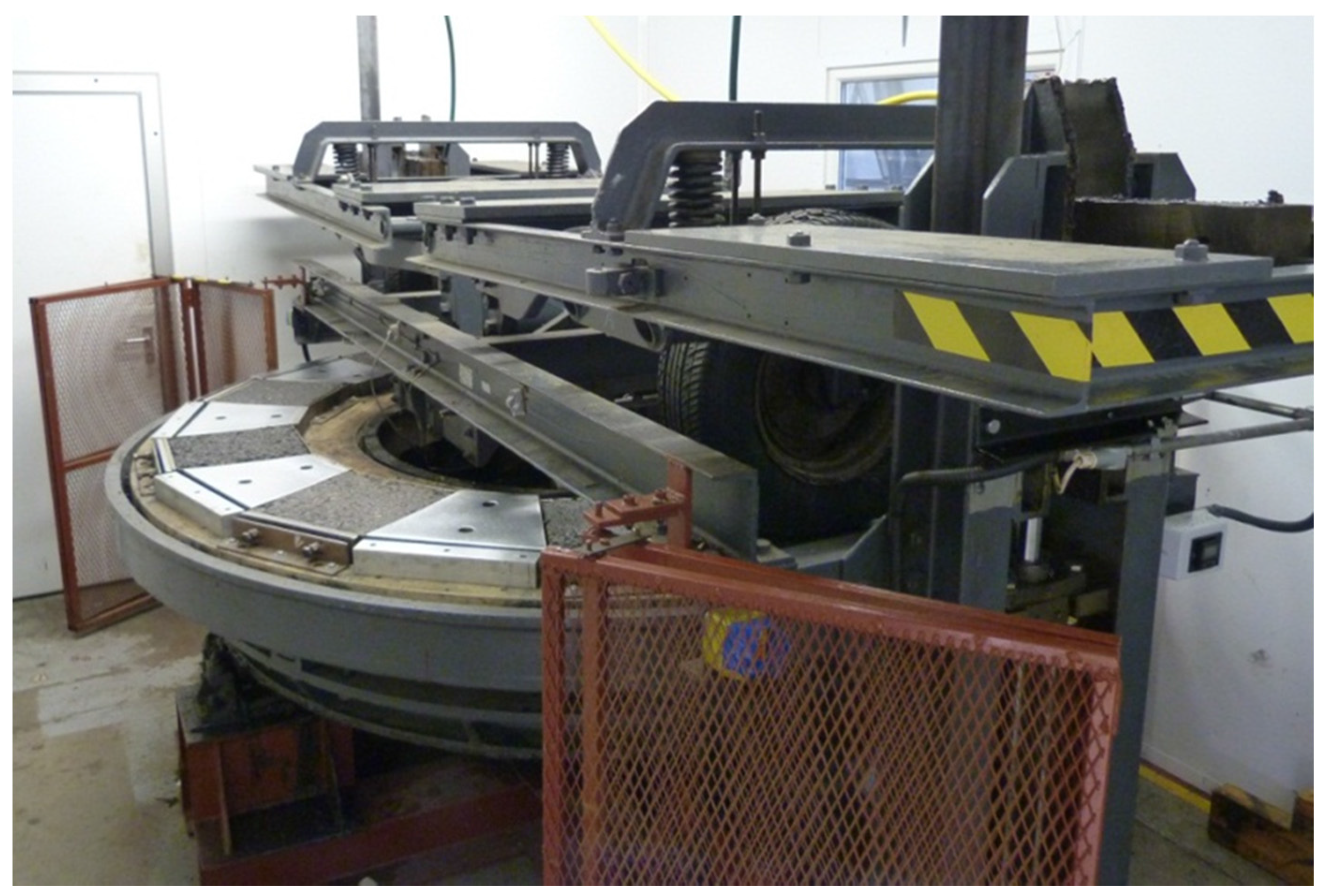
20] contains a generic description of the test equipment used to perform the Wear Test. There is only one device available for use in the UK. This is known as the Road Test Machine #1 (RTM) and is shown in
Figure 5. This equipment was identified as being suitable to simulate trafficking and so predict wear resistance [
20]. The RTM is now located at Ulster University where it is used in the BBA process of HFS certification. The equipment is used to test other types of asphalt and concrete products under conditions of simulated wear. This allows direct comparison of HFS data with other types of asphalt or concrete products used as a road surfacing.
The RTM equipment consists of a 2.1 m diameter table that rotates at 10 rpm or 1.1 m/s. The table has spaces for mounting ten 305 mm × 305 mm × 50 mm test specimens. These are typically asphalt slabs made using a roller compacter unto which the HFS is applied. Two vertically mounted full-size 195/70R14 tyres run freely on the table each applying a load of approximately 5kN. Tyre inflation pressure is maintained at 2 bar or 30 psi. During testing the tyres track back and forth across the width of the test specimen generating additional stress. The RTM is enclosed in a temperature controlled room with testing carried out at 10 ± 2 °C to avoid deformation of the test specimen. The Wear test is carried out in a dry condition with no abrasive.
The Appendix H Wear test method requires initial test values and after 100,000 wheel passes, i.e., 50,000 rotations of the table. However, test values at the start and finish of accelerated testing does not adequately show what happens during the period of simulated trafficking. Understanding what happens during testing offers improved insight into time related changes which relate to in-service trafficking conditions. Simulated trafficking is typically stopped at regular intervals to measure change in HFS properties e.g. 0, 100, 500, 1000, 20,000, 50,000 and 100,000 wheel passes. Each test specimen is photographed to assess erosion loss and assessed for wet skid resistance value (SRV) and texture depth using the British pendulum and sand patch test methods respectively.
Tyre tread depth is measured as an indicator of HFS wear resistance.
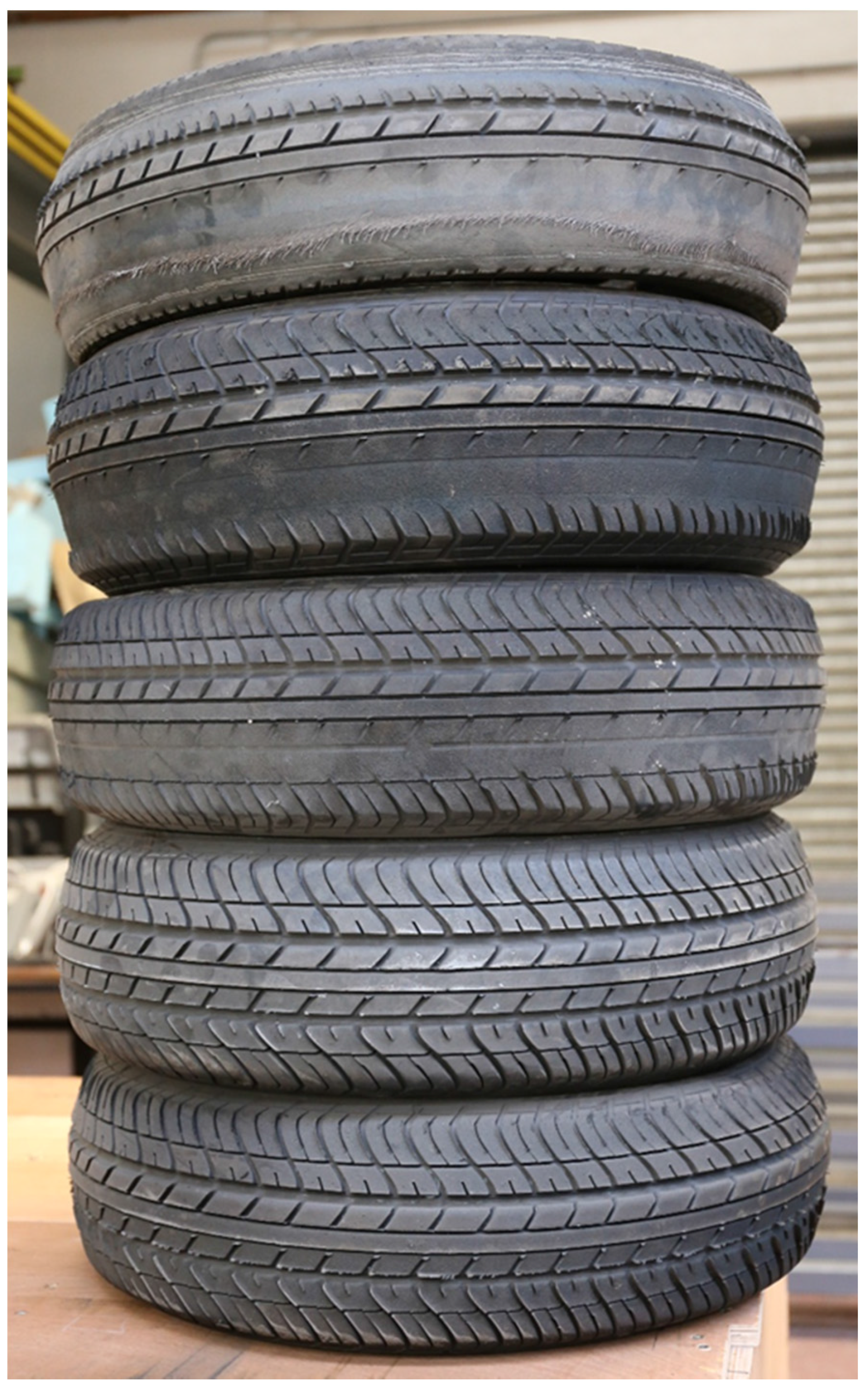
Figure 6 shows five tyres after testing different HFS and asphalt road surface materials. Each tyre was new at the start of its testing.
Figure 5 shows the tyre condition after 50,000 wheel passes (Note: two tyres are used during the Wear test to give a combined total of 100,000 wheel passes). Comparison of the five tyres illustrate the levels of contact stressing experienced within the contact patch depending on the road surfacing material being assessed. The upper three tyres relate to testing just three test specimens of HFS. The lower two tyres relate to testing 10 test specimens of asphalt made with PSV 60+ coarse aggregate.
The HFS tyres show much greater amounts of wear under the same RTM test conditions reflecting the difference between HFS and asphalt in terms of tyre/surface interface contact. The topmost tyre is the result of testing one of the best Type 1 systems available in the UK. The HFS is cold applied and made with calcined bauxite from Guyana. The 3 mm aggregate particles maintained their sharp edges throughout testing and have worn the tyre to such an extent that the wire contained within the carcass has become exposed.
The second tyre relates to testing a Type 1 cold applied HFS made with calcined bauxite that has also resulted in considerable tyre wear. The third tyre relates to a Type 2 cold applied HFS that was a blend of calcined bauxite and PSV 60+ natural aggregate. The amount of tyre tread wear is noticeably less than the top two tyres which both assessed 100% calcined bauxite.
The bottom two tyres show relatively little wear after 100,000 wheel-passes. In their respective wear tests, all 10 spaces on the RTM had been used to test different types of Stone Mastic Asphalt (SMA), Asphalt Concrete (AC) and Thin Surface Course Surfacing systems (TSCS) made with natural aggregates. These have a different type of interface between the asphalt surface and the tyre. Rather than bite into the rubber causing wear, the tyre causes the larger aggregate particles making up the surface of the asphalt mixes to become polished. None of these asphalt mixes would have met the requirements for Type 3 HFS after wear testing.
3. Results
The following gives typical Wear test examples to show what may be expected for different types of aggregate when used in HFS. It is important for anyone considering the use of HFS that an extreme form of simulated trafficked be used to prove whether the chosen aggregate will provide a surfacing that will result in less serious and fatal accidents. The following examples show the importance of aggregate type.
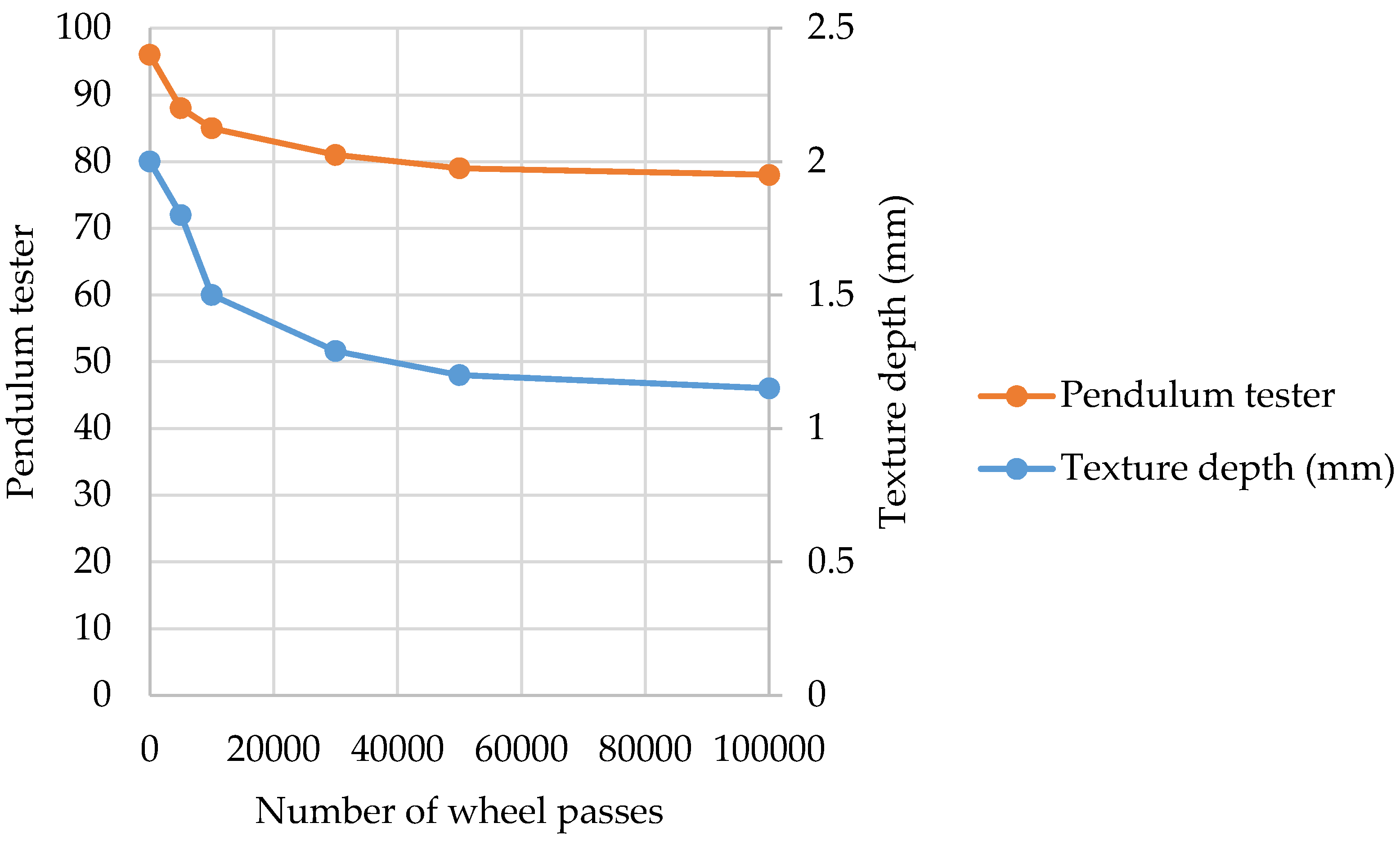
The first example, shown in
Figure 7 plots Wear test data for one of the best types of cold applied Type 1 HFS developed in the UK in recent years. In this example the aggregate is calcined bauxite from Guyana. The plot shows how the aggregate is able to withstand severe simulated trafficking conditions and not become polished. The SRV, measured using pendulum tester, after 100,000 wheel passes is 78 meeting the requirements for Type 1. Texture depth decreases to a value of 1.15 mm. Lower texture values are adequate as the vehicle tyres get pushed into the HFS texture as a result of load transfer during severe braking or turning events.
The next example illustrates how the Wear test may be used to investigate the replacement of calcined bauxite with 100% natural aggregates [
21]. This example re-creates the original Colnbrook By-Pass road trial which found refractory grade calcined bauxite to out-performance all the natural aggregates used. This investigation is based on nine different types of natural aggregate and uses calcined bauxite from Guyana as a control.
Table 1 gives basic details for the 10 rock types assessed, i.e., rock type, description and declared PSV. This is the value of PSV declared by an aggregate supplier as being typical of their source. The aggregates were chosen to represent the range of rock types locally available in the UK. It is important to acknowledge that a declared PSV value is assessed using 10 mm sized aggregate and may not reflect the level of wet skid resistance that would result should the same aggregate be used as a 3mm nominal size in HFS.
The natural 3 mm aggregates used were prepared in the laboratory from crushing larger sizes ranging from lump rock, 50 mm to 14 mm sized chippings. This was done using a jaw crusher. This showed that crushing is important to achieving a good cubic shape. One of the beneficial properties of calcined bauxite is cubic shape with sharp edges. Crushing found that the jaw crusher had to be kept choked to achieve good shape otherwise a flaky and elongate 3 mm particle was formed. The 3 mm aggregates with poorest shape were Granite A and the quartzite reflecting their geological composition.
The grading used to prepare the HFS test specimens was based on the size distribution of the calcined bauxite. This resulted in a similar 2 mm to 4 mm grading being used to prepare all the HFS test specimens for Wear testing. The cold applied HFS test slabs were made according to the guidelines set out in Appendix E [
20]. This uses a 305 mm × 305 mm × 50 mm asphalt base slab prepared using a roller compactor. Duct tape was fixed around the edge of the asphalt base slab to contain the resin. A two-part resin was poured on to the surface of the asphalt slab and spread evenly to give a layer approximately 2–3 mm thick. The aggregate was applied to each slab to excess. No rolling was used. The slab was allowed to cure. All 10 slabs were subjected to simulated wear using the RTM in accordance to Appendix H [
20].
Table 2 summarizes the initial skid resistance and texture depth data. This shows all the un-trafficked cold applied HFS test specimens to have approximately the same pendulum tester value (SRV) and texture depth irrespective of rock type. The calcined bauxite test specimen did not have the highest unpolished SRV. It had an average skid resistance comparable with Limestone B. It had one of the lowest texture depth values.
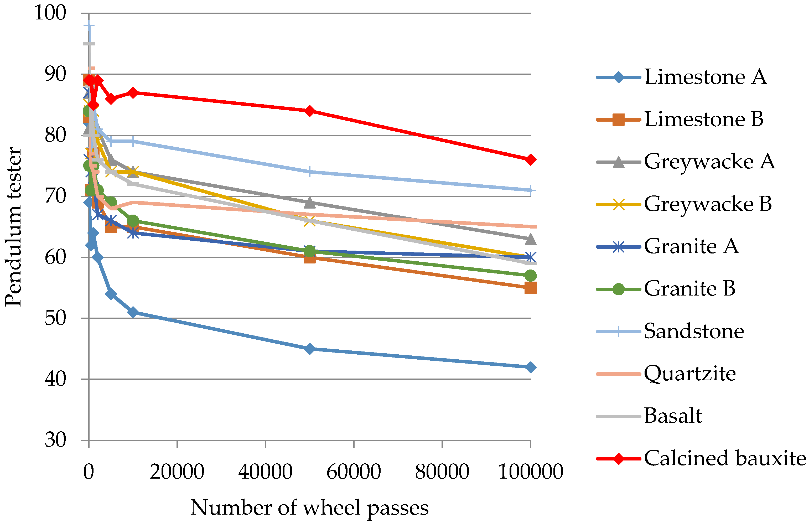
The performance of calcined bauxite becomes apparent in
Figure 8 which shows how wet skid resistance changes during the 100,000 wheel pass test. The effect of rock type on wet skid resistance longevity is apparent with the calcined bauxite having the highest pendulum value of 76 meeting the requirements for Type 1. The PSV 70 sandstone just met the Type 1 requirement with a value of 71.
The quartzite had a pendulum value of 65 just meeting the requirement for Type 2. The remainder of the natural aggregates did not meet the requirement for Type 3. The final skid resistance ranking relates to rock type with the two greywackes having 63 and 60, the basalt having 59, the two granites having 60 and 57 with the two limestones having the lowest values of 55 and 42.
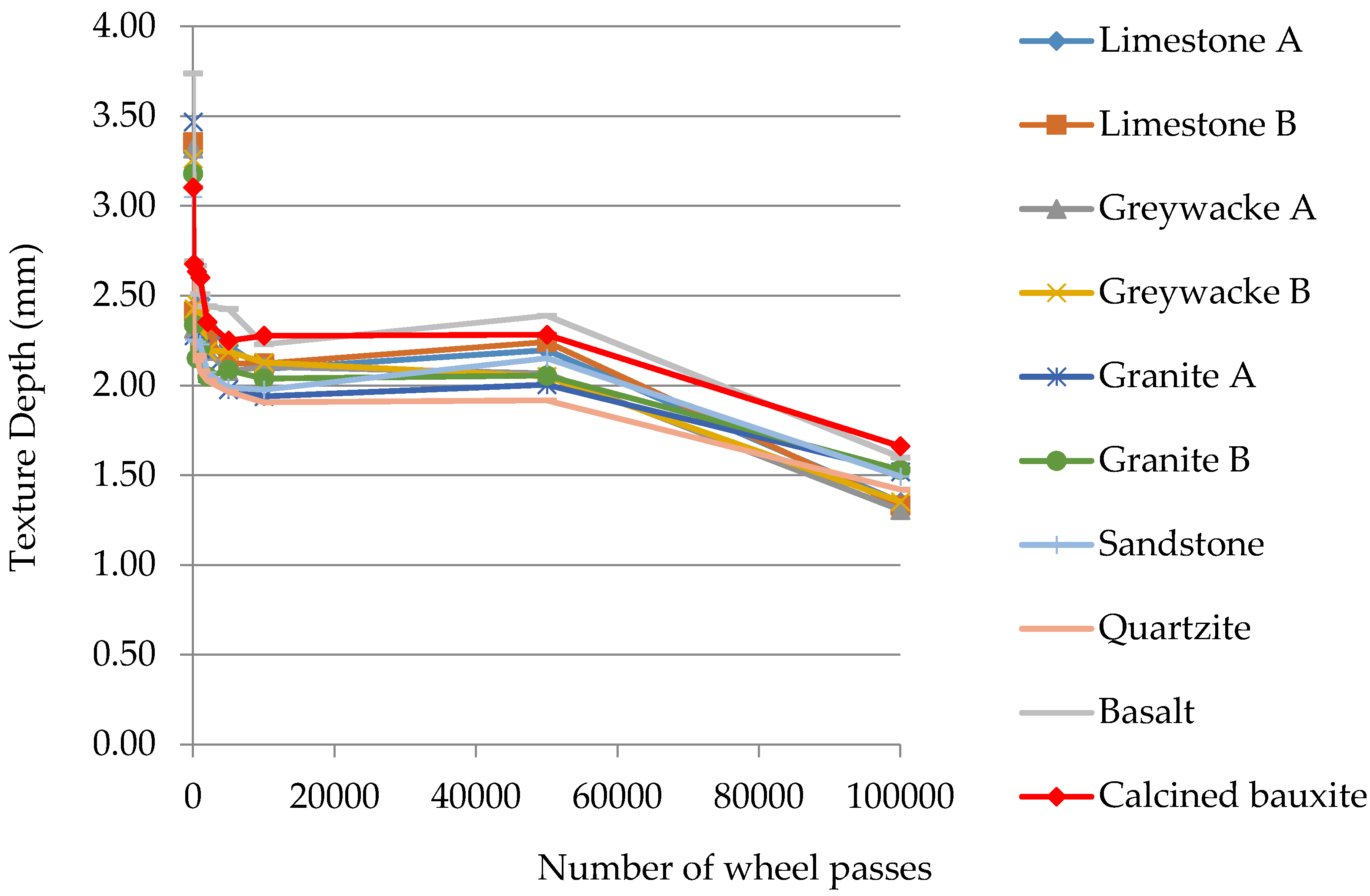
Figure 9 plots the change in texture depth during the 100,00 wheel pass test. This shows the calcined bauxite to have best texture depth after testing reflecting its resistance to extreme wear testing.
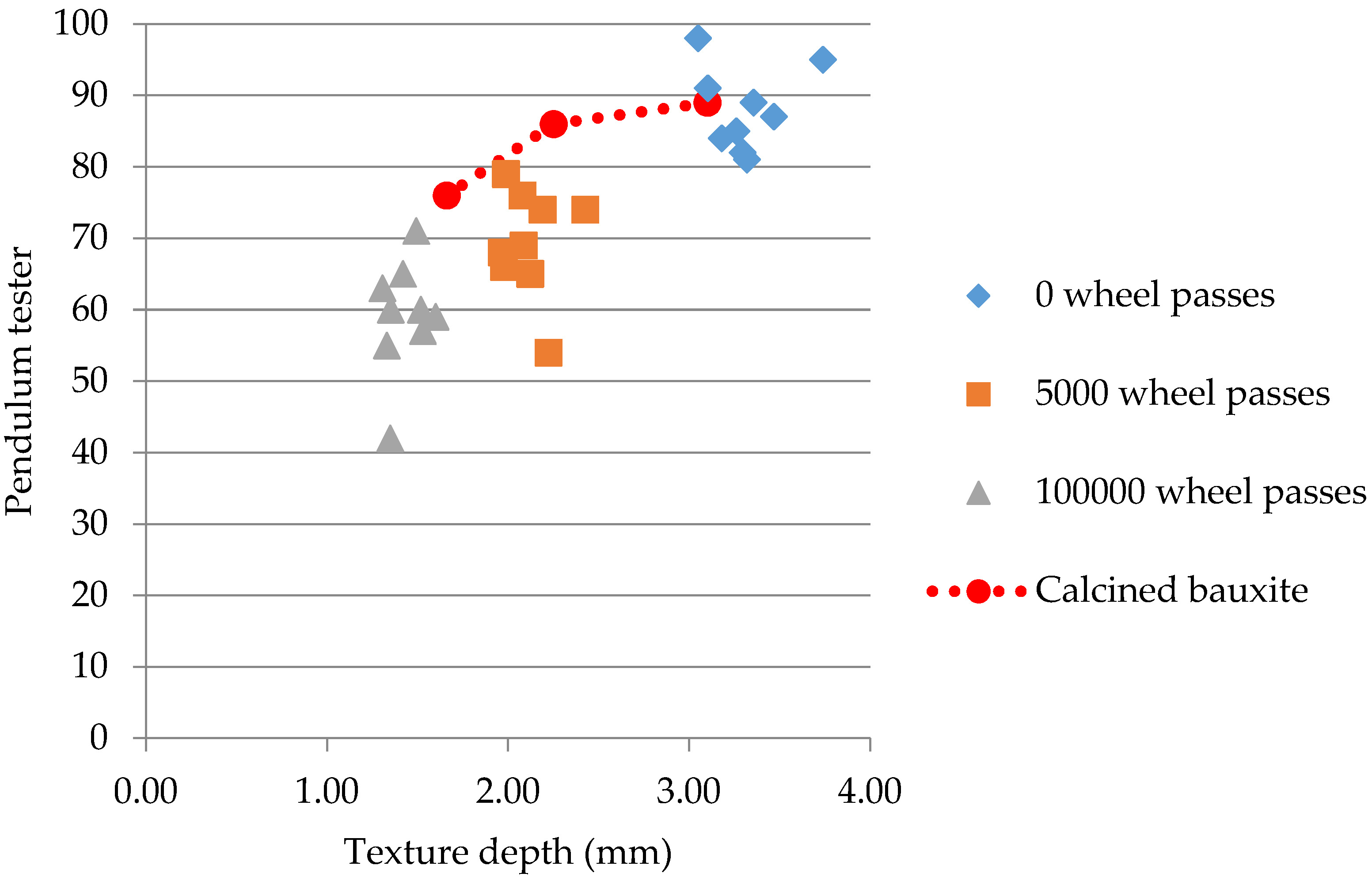
Figure 10 plots the relationship between pendulum value and texture depth at three stages during the Wear test, i.e., initially, after 5000 wheel passes and after 100,000 wheel passes. This shows the loss of both texture depth and wet skid resistance with time, i.e., number of wheel passes. Also plotted is the track of what happens to the calcined bauxite HFS test specimen. This shows how the calcined bauxite developed both best wet skid resistance and texture depth values for the 10 rock types assessed over the 100,000 wheel pass test.
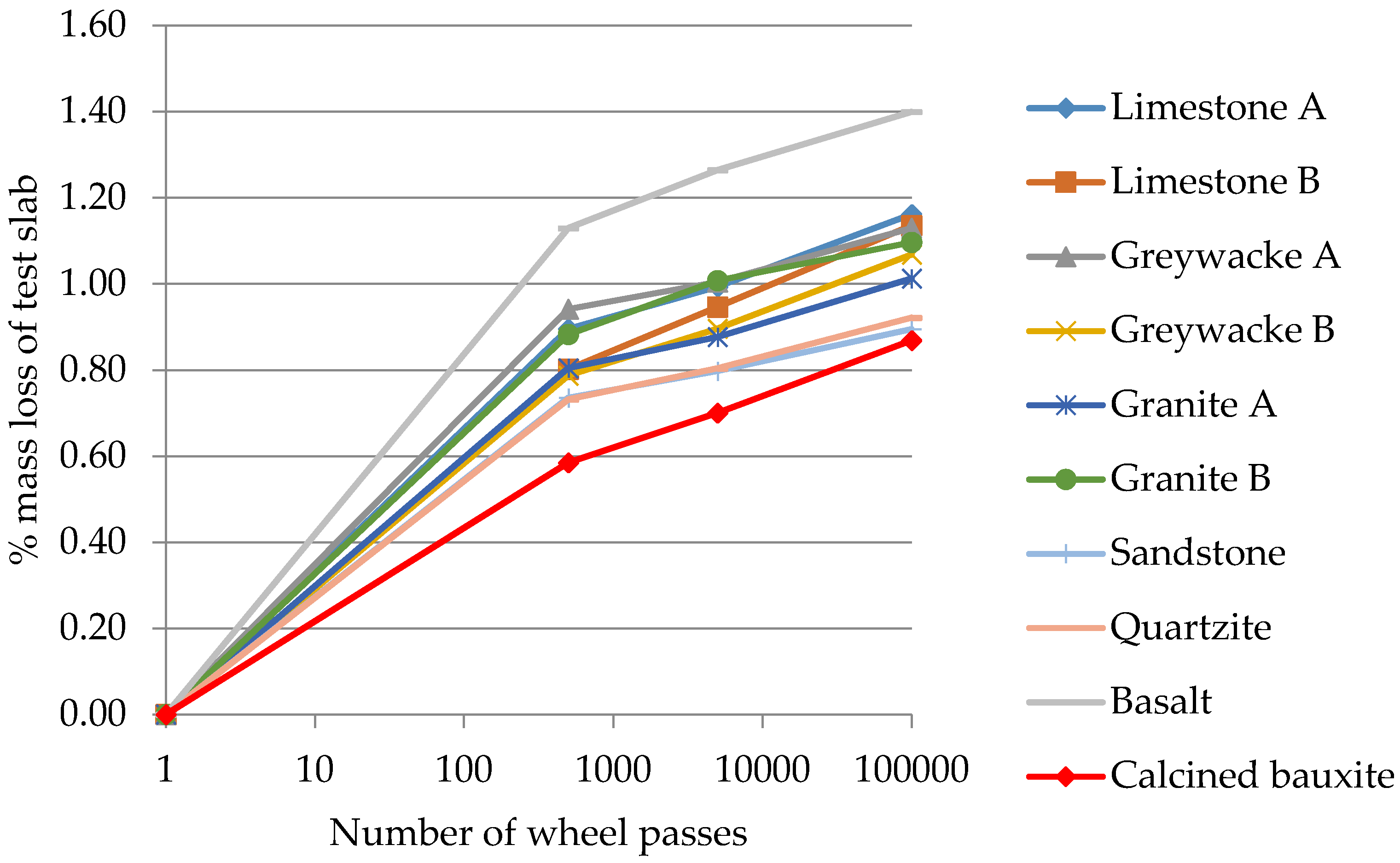
Figure 11 plots the development of % mass loss of each HFS test specimen during the 100,000 wheel-pass Wear test. A log scale has been used to plot the wheel-pass data. This shows the calcined bauxite HFS test specimen to have the smallest mass loss. All the natural aggregates except for basalt are closely grouped. The plots all show that most mass loss occurs during the very early life period of simulated trafficking. In practise this relates to initial loss of aggregate particles that were not fully embedded in the resin binder. Thereafter, there is a relatively small linear increase in mass loss relating to wear of the aggregate particles. This wear loss relates to rounding of individual aggregate particles embedded in the resin binder. The smallest amount of loss was for the calcined bauxite reflecting its resistance to wear.
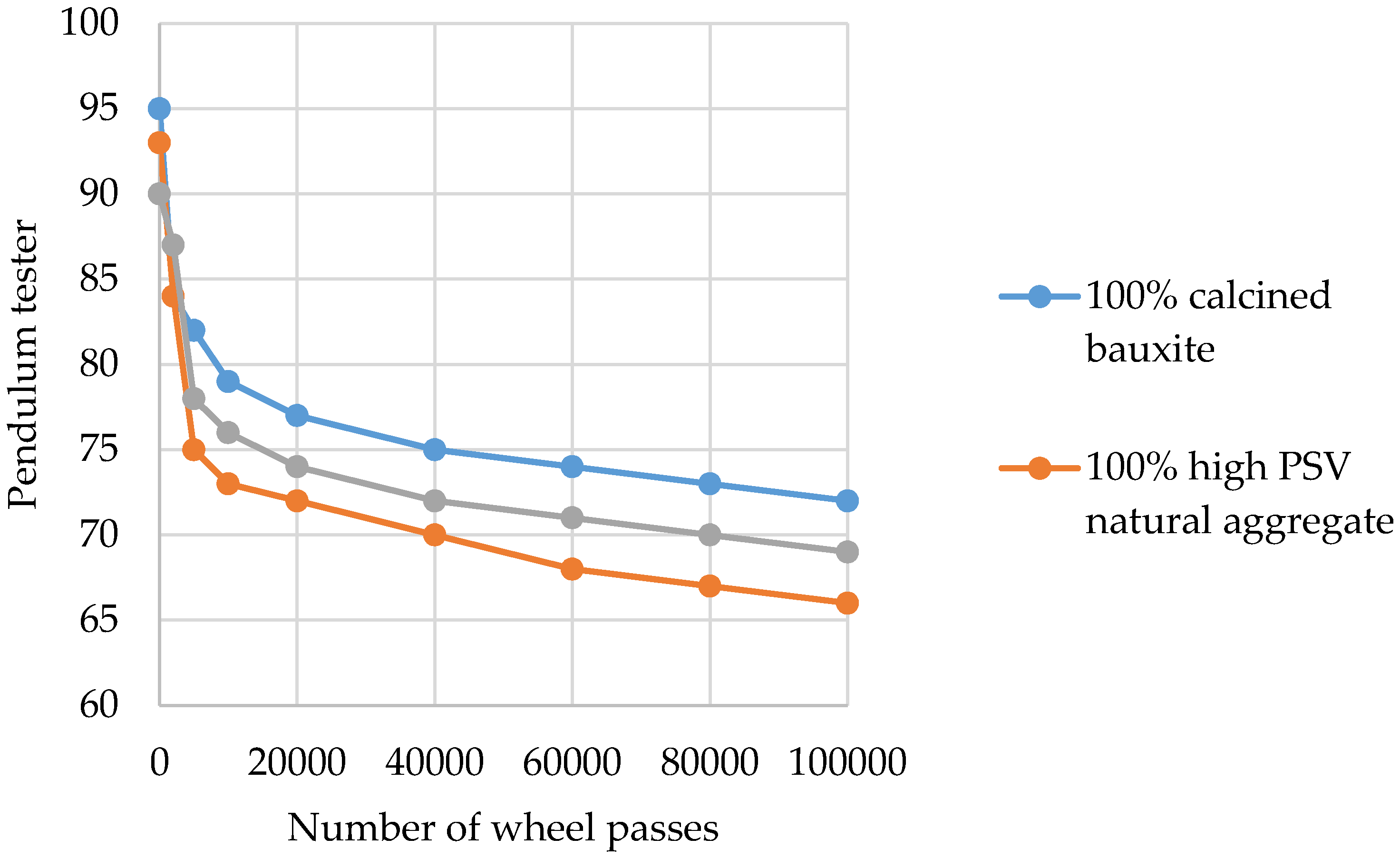
The example shown in
Figure 12 illustrates typical data that may result with the blending of calcined bauxite with a PSV 70 natural aggregate. The 100% calcined bauxite HFS resulted in a pendulum value of 72 after 100,000 wheel passes, i.e., it meets the Type 1 requirement. The 100% high PSV natural aggregate resulted in a value of 66, i.e., meeting the requirements of Type 2. The blend of 60% calcined bauxite and 40% high PSV 70 natural aggregate resulted in a value of 69 which just fails to meet the Type 1 requirement of >70. This data suggests that increasing the percentage of calcined bauxite in the blend should result in a value of wet skid resistance after 100,000 wheel passes that meets the Type 1 requirement of 70.
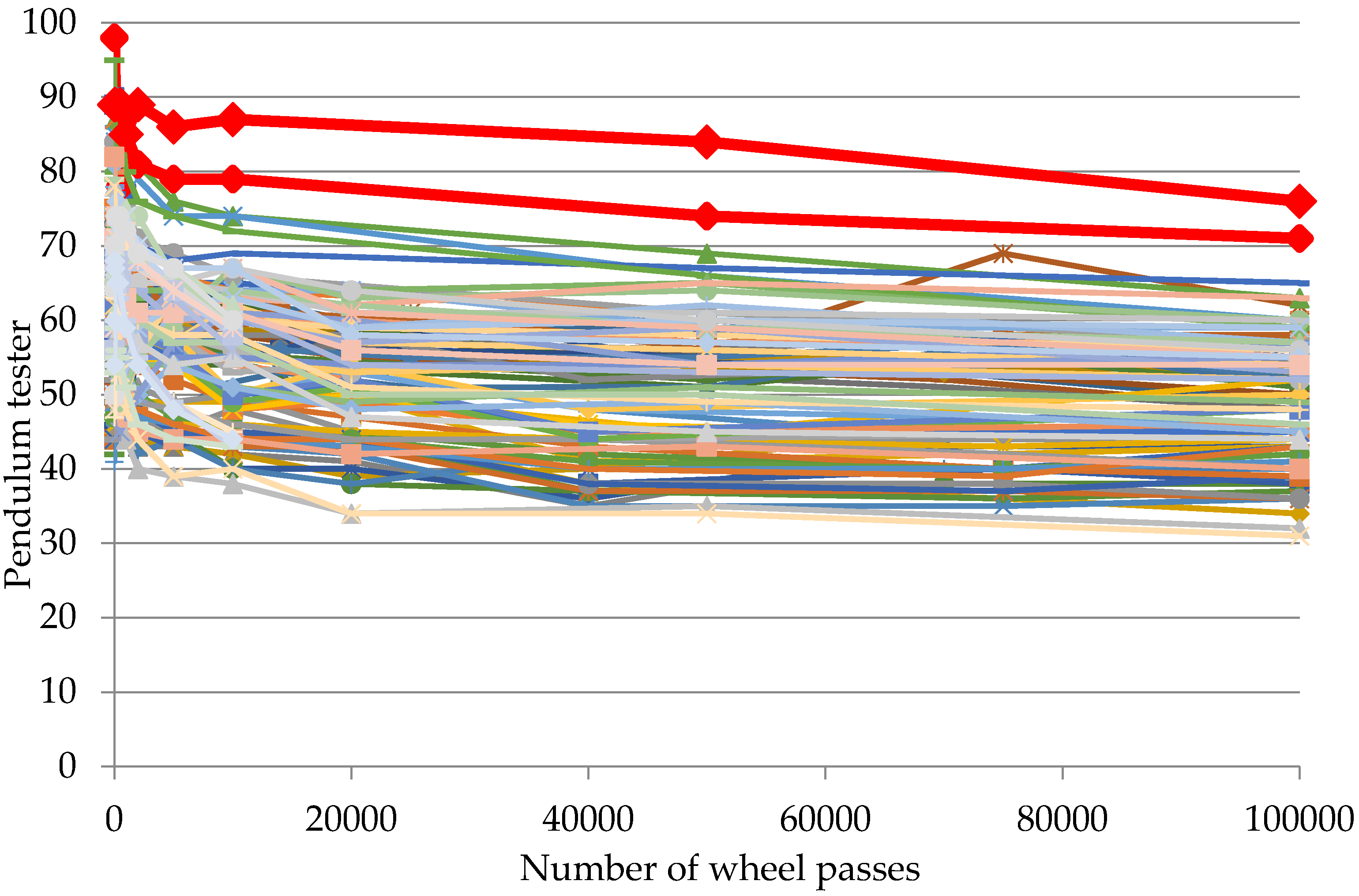
The final example illustrates a data-set of Wear test data compiled by Friel [
22].
Figure 13 shows the change in wet skid resistance measuring using pendulum tester for an extensive range of asphalt and concrete mixes. For comparison purposes data for two HFS systems made with 100% calcined bauxite are given. These are the only two plots in this data-set that have a wet skid resistance value >70. In this composite collection of asphalt and concrete mixes, the final wet skid resistance values after 100,000 wheel passes ranges from 65 to 31. This illustrates that the highest levels of wet skid resistance are only achievable with HFS made with calcined bauxite.


