Review

Research Progress of Single-Mode Quantum Cascade Lasers

1
College of Physics and Electronic Engineering, Hainan Normal University, Haikou 571158, China
2
Hainan Provincial Key Laboratory of Laser Technology and Optoelectronic Functional Materials, Innovation Center of Hainan Academician Team, Haikou 571158, China
3
Hainan International Joint Research Center for Semiconductor Lasers, Hainan Normal University, Haikou 571158, China
*
Author to whom correspondence should be addressed.
Coatings 2025, 15(8), 950; https://doi.org/10.3390/coatings15080950
Submission received: 11 July 2025 / Revised: 1 August 2025 / Accepted: 11 August 2025 / Published: 13 August 2025
(This article belongs to the Special Issue Advancements in Lasers: Applications and Future Trends)

Abstract

Quantum cascade lasers (QCLs) are important laser sources in the mid-infrared band. Among them, single-mode quantum cascade lasers show significant advantages in key performance such as output wavelength stability and narrow linewidth. These lasers have broad application prospects in fields such as gas detection, component analysis, and medical diagnosis. Single-mode quantum cascade lasers are mainly achieved through distributed feedback (DFB) gratings and distributed Bragg reflector (DBR) gratings. This paper presents the basic principles of quantum cascade lasers and summarizes the research progress of distributed feedback quantum cascade lasers and distributed Bragg reflector quantum cascade lasers in recent years, respectively. Finally, an in-depth discussion and outlook on the development direction and research trends of single-mode quantum cascade lasers are presented.

1. Introduction

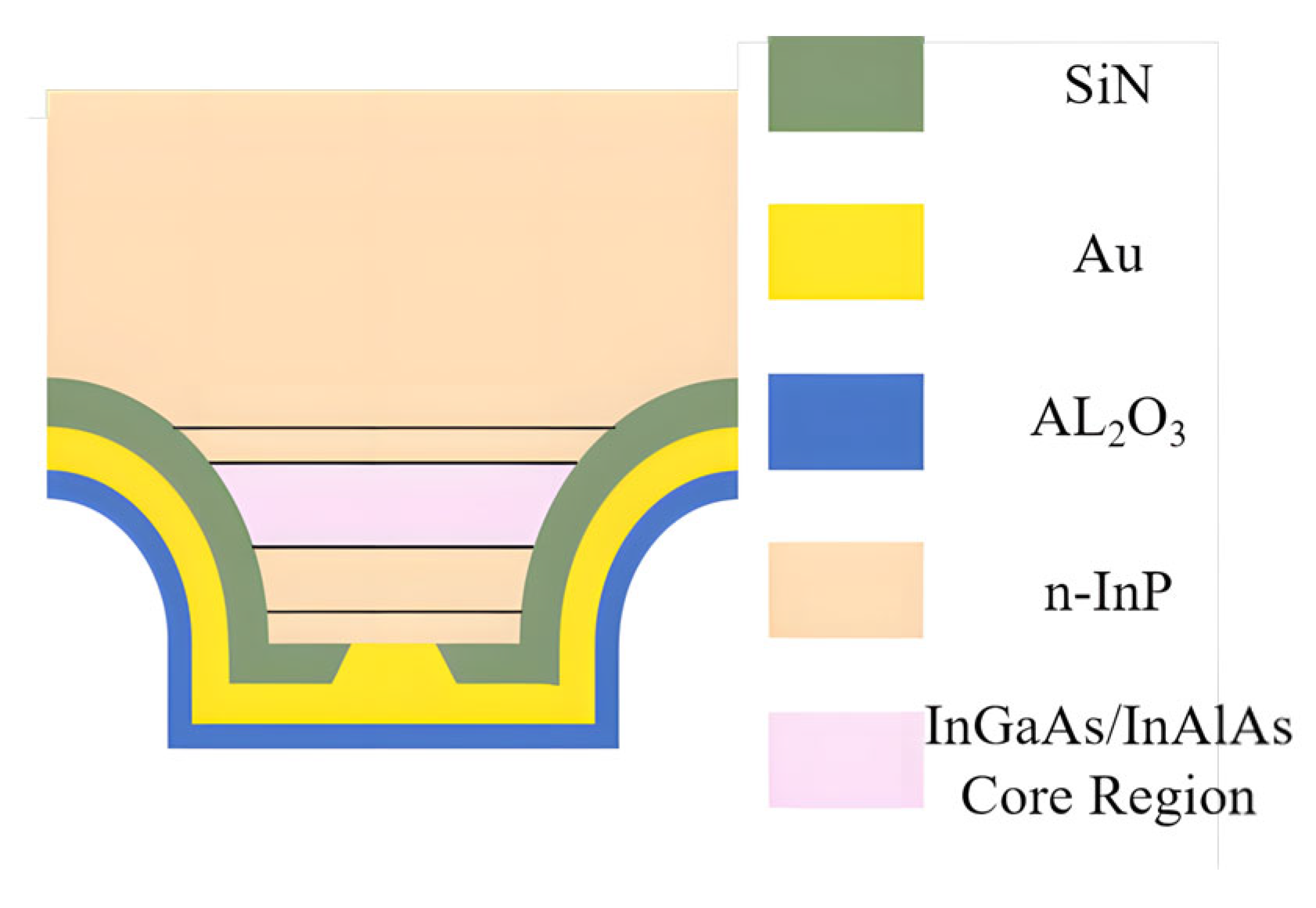
Quantum cascade lasers rely on intersubband transitions within carefully engineered coupled quantum well structures in the conduction band. Electrons sequentially traverse these structures undergoing optical transitions between quantized subbands emitting photons where the wavelength is precisely determined by the designed energy difference between these subbands, as shown in Figure 1. The effective refractive index neff is fundamental to the laser’s optical feedback mechanism particularly in distributed feedback designs where it determines the resonant wavelength selected by the grating structure according to the Bragg condition, ensuring single-mode operation [1]. QCLs offer high power (watt-level CW) [2,3], narrow linewidth (<1 MHz) [4,5], and wavelength customizability, making them vital for gas sensing, communications, and astronomy. However, traditional Fabry–Perot cavities exhibit broad gain spectra, exciting multi-longitudinal modes that reduce spectral purity. This fails in high-precision applications like trace gas detection and high-speed coherent communication.
To break through the single-mode bottleneck, distributed feedback (DFB) and distributed Bragg reflector (DBR) technologies have become two core solutions.
DFB-QCL achieves global distributed feedback mode selection by etching Bragg gratings (periodic satisfaction) on the waveguide layer λ B = 2 n e f f Λ / m , where λ B is the Bragg wavelength; neff is the effective refractive index; Λ is the grating period; and m is the diffraction order. Its technological advancements include the following:
In terms of low-power-consumption breakthroughs, Bismuto et al. achieved low-threshold operation of approximately 0.65 kiloamperes per square centimeter in a broader mid-infrared band [6]. This indicates that the power consumption of quantum cascade lasers (QCLs) has been significantly reduced through material growth optimization and active region design, especially by lowering the threshold current density.
In terms of high-power output, Lu et al. developed a room-temperature continuous-wave distributed feedback quantum cascade laser (DFB-QCL) with a power of 2.4 W (a wavelength of approximately 4.6 μm) [2,3]. This achievement demonstrates that while maintaining single-mode characteristics, the output power of DFB-QCLs has been increased to meet practical application requirements by optimizing waveguide design, grating coupling efficiency, and thermal management.
In terms of wide-tuning designs, Slivken et al. used sampled grating and digitally cascaded grating technologies to cover a tuning range of 8.2–9.8 μm (output power: >500 mW) [7,8]; Mansuripur et al. achieved continuous tuning of 230 cm−1 using dual-sampled mirrors [9]. This shows that complex grating designs (such as sampled gratings) and electronic tuning mechanisms have successfully overcome the limitation of the narrow tuning range of traditional distributed feedback lasers.
In terms of high-temperature stability, Yoshinaga et al. maintained single-mode lasing at a wavelength of 7.4 μm under 200 °C pulsed conditions [10]. This reflects that by optimizing material systems (such as strain-compensated InGaAs/InAlAs), active region design, and device structures (such as optimized heat dissipation channels), QCLs can work stably in harsh thermal environments.
The DBR-QCL uses an end-face Bragg mirror for mode selection, which is limited by the length L of the gain region. u F S R > 1 2 u D B R , where u F S R is the free spectral range and u D B R is the bandwidth of the distributed Bragg reflector. Recent breakthroughs include the following:
In terms of innovation in long gain regions, Bai et al. proposed a strategy where the gain spectrum partially overlaps with the reflection spectrum of the distributed Bragg reflector (DBR), achieving a 2.7 terahertz (THz) single-mode laser (side-mode suppression ratio (SMSR): >25 decibels) in a 3.6 mm gain region [11]. This indicates that through careful design of the matching between the gain spectrum and the reflection spectrum, the DBR structure can support longer gain regions.
In terms of beam and thermal management, Yao et al. compressed the divergence angle to 4.4° × 4.4° based on photonic crystals; Olariu et al. adopted a thermal bridge design with embedded benzocyclobutene (BCB) dielectric layers, increasing the duty cycle to 30% [12,13]. This reflects that the beam quality of QCLs has been significantly improved through innovative optical structure design (photonic crystals) and optimization of thermal interface materials/structures (BCB thermal bridges).
In terms of key thermal challenges, Lu’s photonic crystal cavity achieved an output of 3.88 THz, highlighting thermal management’s role, with new structures offering solutions [5].
Addressing the core challenges in achieving high-performance single-mode QCLs is intrinsically linked to advancements in material science, precise surface and interface engineering (e.g., Ohmic contacts, bonding interfaces, and waveguide-cladding interfaces), and the design and fabrication of critical functional micro/nano-structures, particularly the DFB gratings and DBR mirror stacks, which can be viewed as specialized optical ‘coatings’ or surface micro-structures. The technological advances in single-mode QCLs reviewed in this work are fundamentally underpinned by innovations in materials science and coating/surface engineering, making this topic highly relevant to the core focus of the journal Coatings.
Table 1 summarizes current key performance metrics for single-mode DFB and DBR QCLs across mid-IR and THz bands. DFBs generally lead in power and high-T stability, while DBRs excel in beam control (low divergence) and specific low-power designs. The tuning range heavily depends on the grating design (e.g., SG). Power consumption and high-T operation remain key challenges for DBRs. Grating fabrication precision critically impacts SMSR and wavelength stability.
Table 2 systematically contrasts core differences between DFB and DBR QCLs in mode control, tuning, thermal/beam management, fabrication, and applications. DFBs achieve superior SMSR and wide electrical tuning (SG) via strong grating coupling (κL > 1), offering high integration but thermal challenges. DBRs select modes via spectral matching (ΔυFSR > ½ ΔυDBR), allowing flexible gain design and beam shaping potential, but mirror thermal stability is critical. Their fabrication complexities differ.

2. Technological Evolution and Challenges of Single-Mode Quantum Cascade Lasers

2.1. Rigid Demand for the Performance of High-Quality Single-Mode QCLs

The core value of single-mode quantum cascade lasers lies in their outstanding spectral purity and beam quality, which are rigid demands in high-end application scenarios. In the field of high-resolution gas detection, such as the simultaneous analysis of multi-component greenhouse gases (CH4/N2O/CO2), it is necessary to ensure that the edge-mode rejection ratio (SMSR) exceeds 30 dB and that the line width is narrower than 2 MHz to avoid measurement errors caused by absorption spectrum overlap. Free-space communication systems rely on near-diffractive limit beams (M2: <1.3) to suppress inter-mode interference caused by atmospheric turbulence and to ensure stability of high-speed data transmission [35]. In quantum precision measurements, such as cold atomic clock frequency locking, laser frequency drift needs to be controlled within 10 kHz/min to meet extreme stability requirements [5]. The traditional multimode QCL has an unstable output due to random mode hopping (frequency shift: >5 cm−1) and high-order mode power competition, which seriously restrict the above applications [36].
Table 3 lists the state-of-the-art levels and enabling technologies for key single-mode QCL performance metrics. The table showcases QCL frontiers in power, tuning, high-T operation, linewidth, and cost. Cascade active regions, digital gratings, strain-compensated materials, external feedback, and CMOS processes are key enablers.

2.2. Unsolved Core Technical Bottlenecks

The current single-mode QCL still faces three core technical bottlenecks. Thermal management bottlenecks are the first to be affected: when operating temperatures exceed 100 °C, mismatch between carrier transport and photon lifetime triggers mode jumps; for example, the maximum duty cycle of terahertz surface-emitting devices is only 30% at 170 K [22]. The contradiction of grating process accuracy is equally prominent. Structures such as sampling gratings require a grating period error of ΔΛ/Λ < 0.1%, which conflicts with the process tolerance for 200 mm wafer-level manufacturing [28]. Furthermore, the trade-off between single-mode purity and electro-optical efficiency has not yet been broken through: although the long gain region design can enhance the output power, it increases the risk of high-order mode ejectors. The DBR-QCL must precisely control the overlap between the gain spectrum and the DBR reflection spectrum to maintain an SMSR of >25 dB, and this balance is highly vulnerable to thermal effects [39].

3. Advances in Research on DBR-QCL

3.1. Chapter Introduction

DBR-QCL overcomes DFB wavelength limitations via decoupled reflector/gain design [9], enabling an SMSR of >35 dB, a tuning of >150 cm−1, and single-mode operation at <1 W. Its evolution focuses on reflector innovation (reduced scattering [32] and thermal stability [40]), precision wavelength control (SG-DBR [9] and gas detection [4]), beam optimization (divergence compression [27] and stability [11]), and system integration (new pulses [41]), driving high-performance single-mode laser advancement (2012–2024).

3.2. Reflector Design and Process Breakthroughs

3.2.1. Low-Loss/Low-Power Design

In 2016, ETH Zurich in Switzerland tested QCLs in continuous-wave mode at room temperature (25 ± 0.5 °C) with a driving current of 750 mA (a threshold current of 680 mA) and reduced thermal resistance to 8.2 K/W through a 1.8 μm thin upper waveguide layer (conventional: 3.5 μm), with a power consumption of 0.87 W (λ = 5.6 μm), an output power of 83.5 mW, an SMSR of 32.8 dB (spectral resolution: 0.1 cm−1), and a slope efficiency of 1.18 W/A. The power fluctuation during the 100 h aging test is less than 2.7% [36].
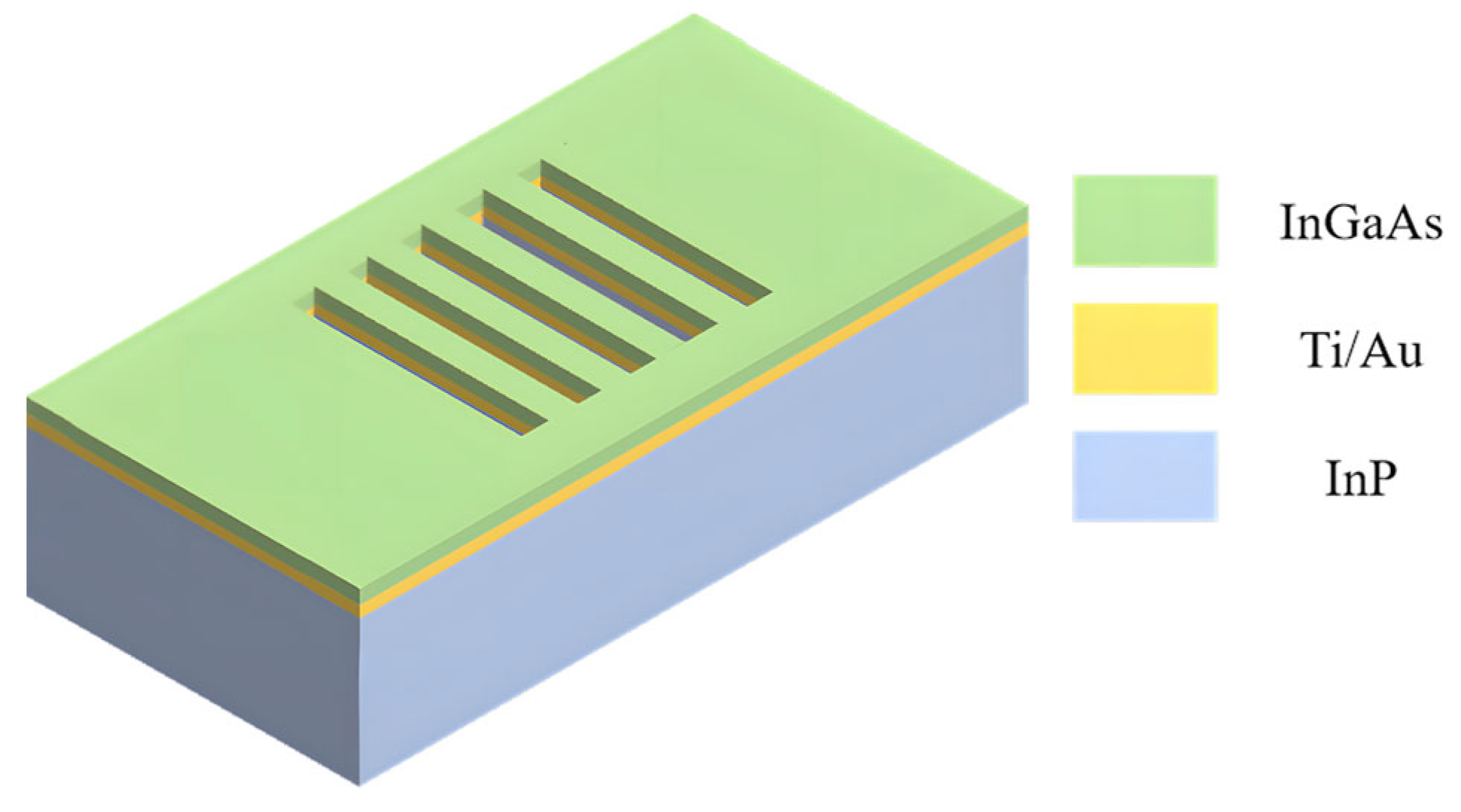
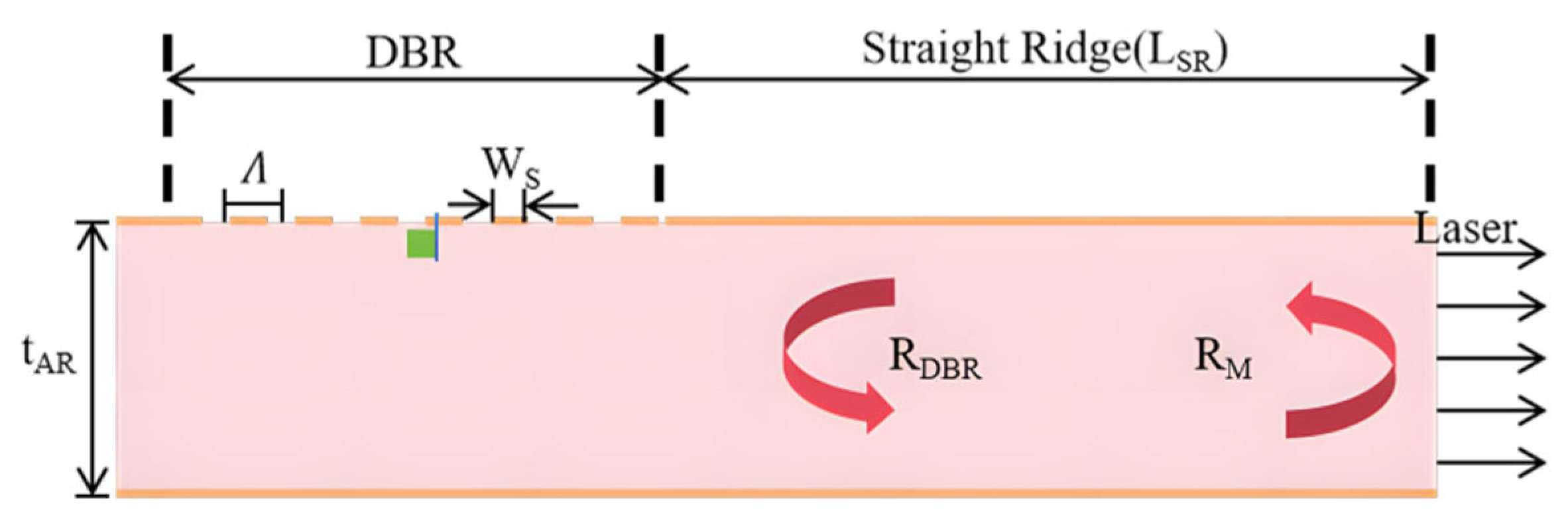
In 2020, the Ioffe Institute of Physics and Technology in Russia fabricated a DBR reflector (current density 1.8 kA/cm2) by ion beam etching using a pulse drive (pulse width: 100 ns, as shown in Figure 2, repetition frequency: 10 kHz) in a low-temperature environment of 80 K. The side wall roughness was reduced to 8.7 nm (AFM verified), and the scattering loss was 34% lower than that of traditional ICP etching (32.5 nm). The output power reaches 128 mW (3.5 THz); the threshold current density is 1.75 kA/cm2 (22% lower than the traditional one), and the SMSR is 26.3 dB (test current: 1.2 × Ith) [32].

3.2.2. Hybrid Structures and Process Tolerances

In 2016, Hamamatsu Photonics, Japan, achieved a thermal tuning sensitivity of ±0.3 cm−1/°C (λ = 7.4 μm) by bonding a DBR reflector to an InP-based QCL chip using silicon-based hybrid integration technology in room-temperature continuous-wave mode (driving current: 850 mA and TEC temperature control: ±0.1 °C), with an output power of 62 mW, an SMSR of 34.2 dB (spectral resolution: 0.2 cm−1), and a wavelength tuning range of 12.5 cm−1 (20–100 °C). It adopts a microchannel heat dissipation structure (thermal resistance: 4.3 K/W), and its power attenuation is less than 8% at 80 °C (100 h test) [40].
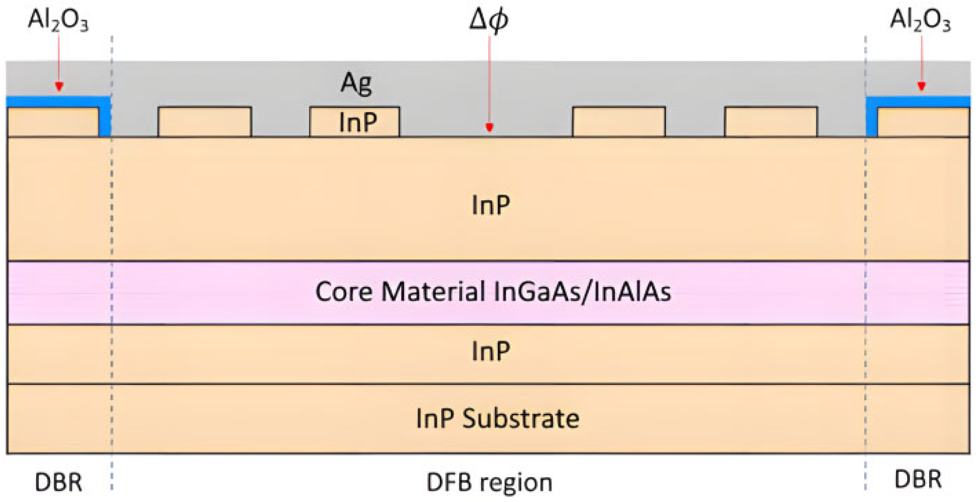
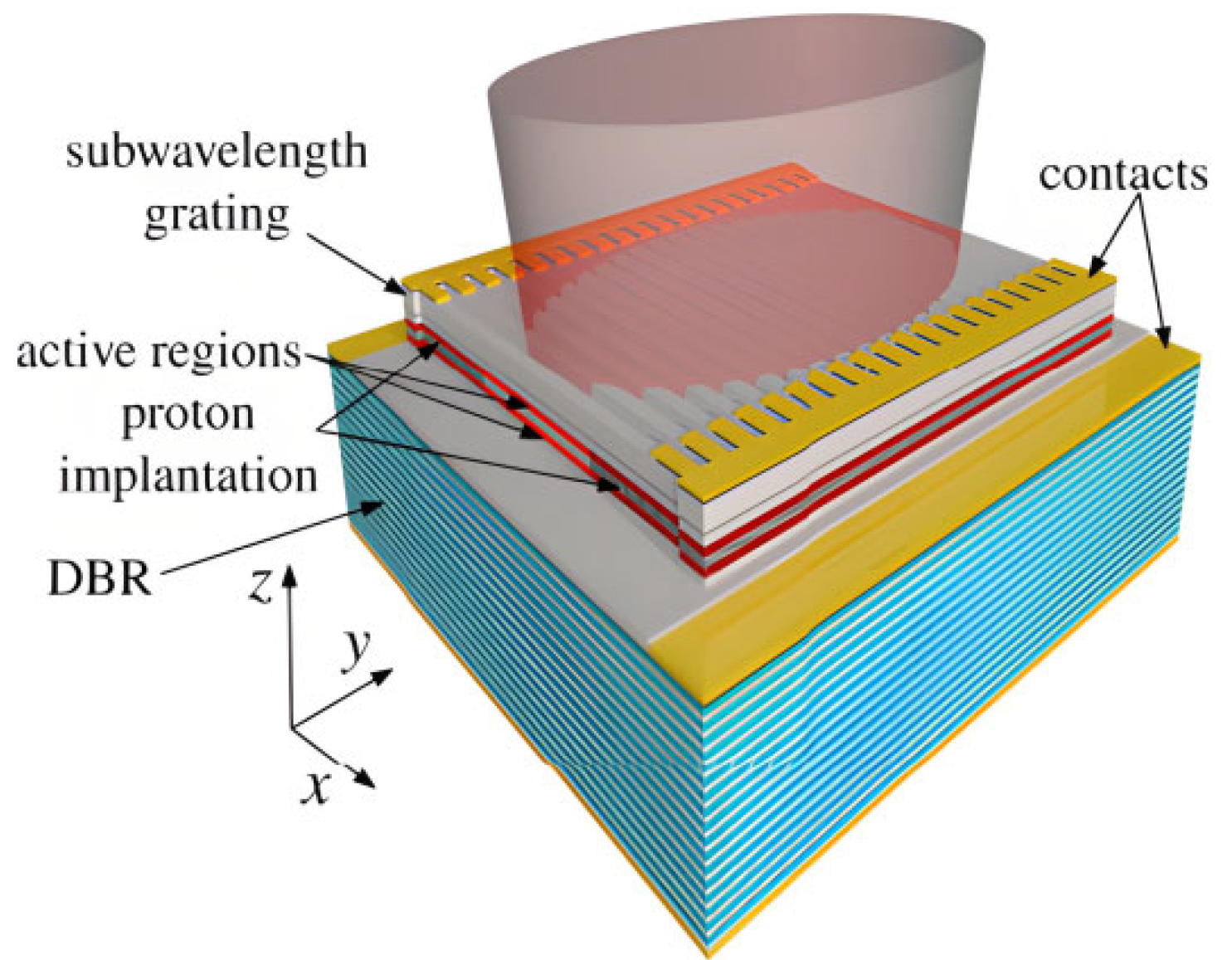
In 2021, the University of Wisconsin–Madison in the United States tested it in room-temperature pulse mode (pulse width: 1 μs and frequency: 50 kHz) with a drive current of 2.8 A (threshold current 2.1 A), as shown in Figure 3. The DFB-DBR hybrid structure combined with a 50 μm wide ridge design (lithography tolerance: ±1.2 μm) achieved a yield of 91.4% (statistics on 30 wafers), with an output power of 2.35 W (λ = 4.6 μm), an SMSR of 33.5 dB (peak wavelength deviation: <0.15 nm), and a divergence angle of 14.3° × 12.8° (E/H plane) [33].

3.3. Wavelength Tuning and High-Temperature Stability

3.3.1. Wide Tuning and Precise Control

In 2012, the Massachusetts Institute of Technology (MIT) in the United States tested a two-segment SG-DBR in room-temperature continuous-wave mode (current: 850 mA and TEC temperature control: ±0.05 °C), with an injection current range of 150–450 mA, achieving a tuning of 156.4 cm−1 (4.62–4.91 μm).Characterized by 57.6 mW average output power, the device achieved 36.7 dB SMSR (full-band >35 dB) with 0.017 cm−1/°C temperature drift coefficient (verified at 5–50°C) and 8.3 ms switching speed under step current response. [9].
In 2015, Princeton University in the United States achieved simultaneous detection of CH4/N2O/H2O in the continuous-wave mode at room temperature (current: 800 mA and TEC temperature: ±0.1 °C) using the SG-DBR tuning technique (based on [16]). The tuning range covered 148.5 cm−1 (1160–1308.5 cm−1), as shown in Figure 4. It had an output power of 61.2 mW (average), an SMSR of >35 dB (full band), and a detection limit up to the ppb level (CH4: 8.2 ppb and N2O: 11.5 ppb). The signal-to-noise ratio is enhanced to 286:1 by wavelength modulation spectroscopy (WMS), and the temperature drift coefficient is controlled at 0.022 cm−1/°C. This application study was classified as a dual breakthrough of wide tuning technology and multi-scenario application (Section 3.3.1 and Section 3.5.2) to verify the practicality of SG-DBR in complex gas detection for the first time [4].
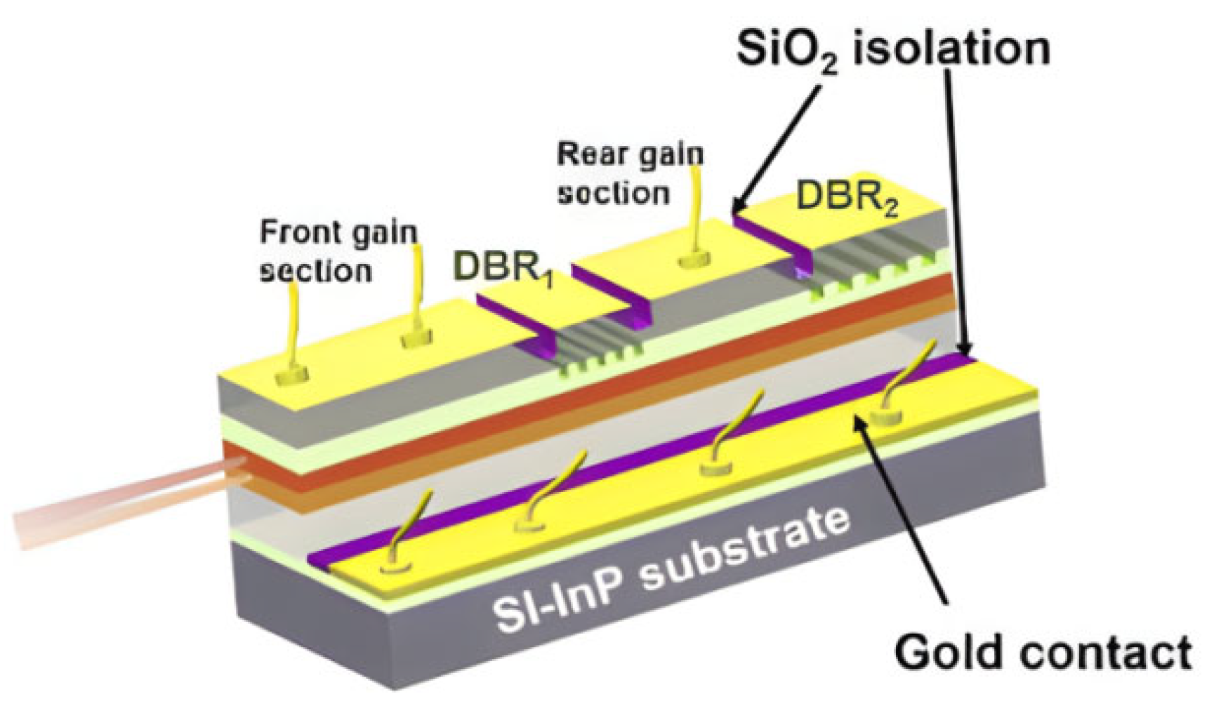
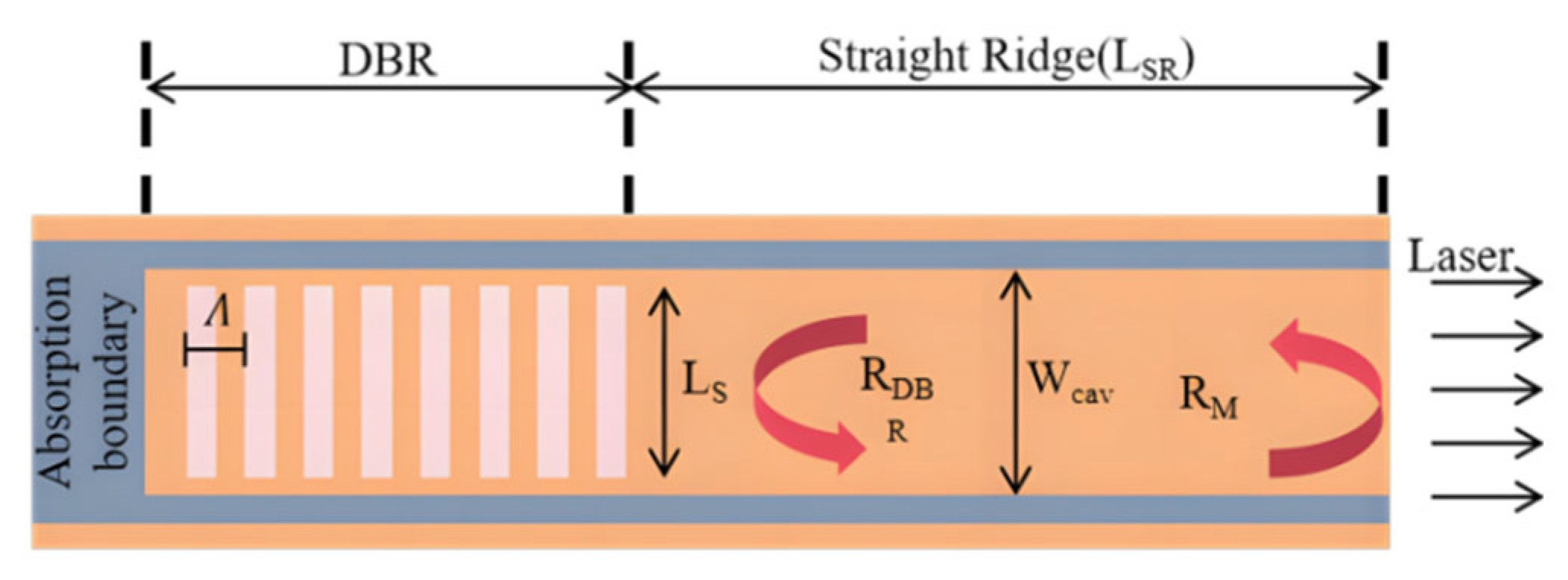
In 2021, the Institute of Semiconductors, Chinese Academy of Sciences, verified the double-shallow etching DBR structure in room-temperature pulse mode (current: 1.8 A and pulse width: 500 ns), achieving dual-wavelength electrical switching through independent electrode control (λ1 = 8.3 μm, λ2 = 9.1 μm, and Δλ = 0.8 μm), as shown in Figure 5. It had a switching speed of <15 μs, an output power of 85 mW/78 mW (dual-channel), an SMSR of >31 dB (full band), and a wavelength stability of ±0.02 cm−1 (test 1000 switching cycles) [24].
In 2023, ETH Zurich achieved dynamic wavelength correction through Si3N4 film deposition (102 ± 3 nm thickness) in the DBR region at a constant temperature of −10 °C (current density: 1.5 kA/cm2 and pulse width: 200 ns), as shown in Figure 6. A tuning accuracy of 0.11 cm−1 (resolution: 0.01 cm−1) compensated for an initial wavelength offset of ±0.57 cm−1 (4.7 THz). The output power is 15.2 mW; the SMSR is 28.4 dB, and the 24 h wavelength drift is less than ±0.031 cm−1 (temperature fluctuation: ±0.1 °C) [12].

3.3.2. Breakthrough in High-Temperature Performance

In 2019, the Fraunhofer Institute for Applied Solid State Physics (Fraunhofer IAF) in Germany, in the continuous-wave mode with a wide temperature range of 25–85 °C (current: 1.1 A and TEC temperature control: ±0.05 °C), achieved thermal tuning using an external Ge-on-SOI DBR with a sensitivity of ±0.31 cm−1/°C (λ = 4.8 μm), as shown in Figure 7. The output power is 105 mW (at 25 °C); the SMSR is 33.6 dB, and the thermal drift coefficient is only 0.009 nm/°C (traditional DBR: >0.4 nm/°C). The power fluctuation after 48 h of continuous operation is less than ±3.2% (at a constant temperature of 60 °C) [19].
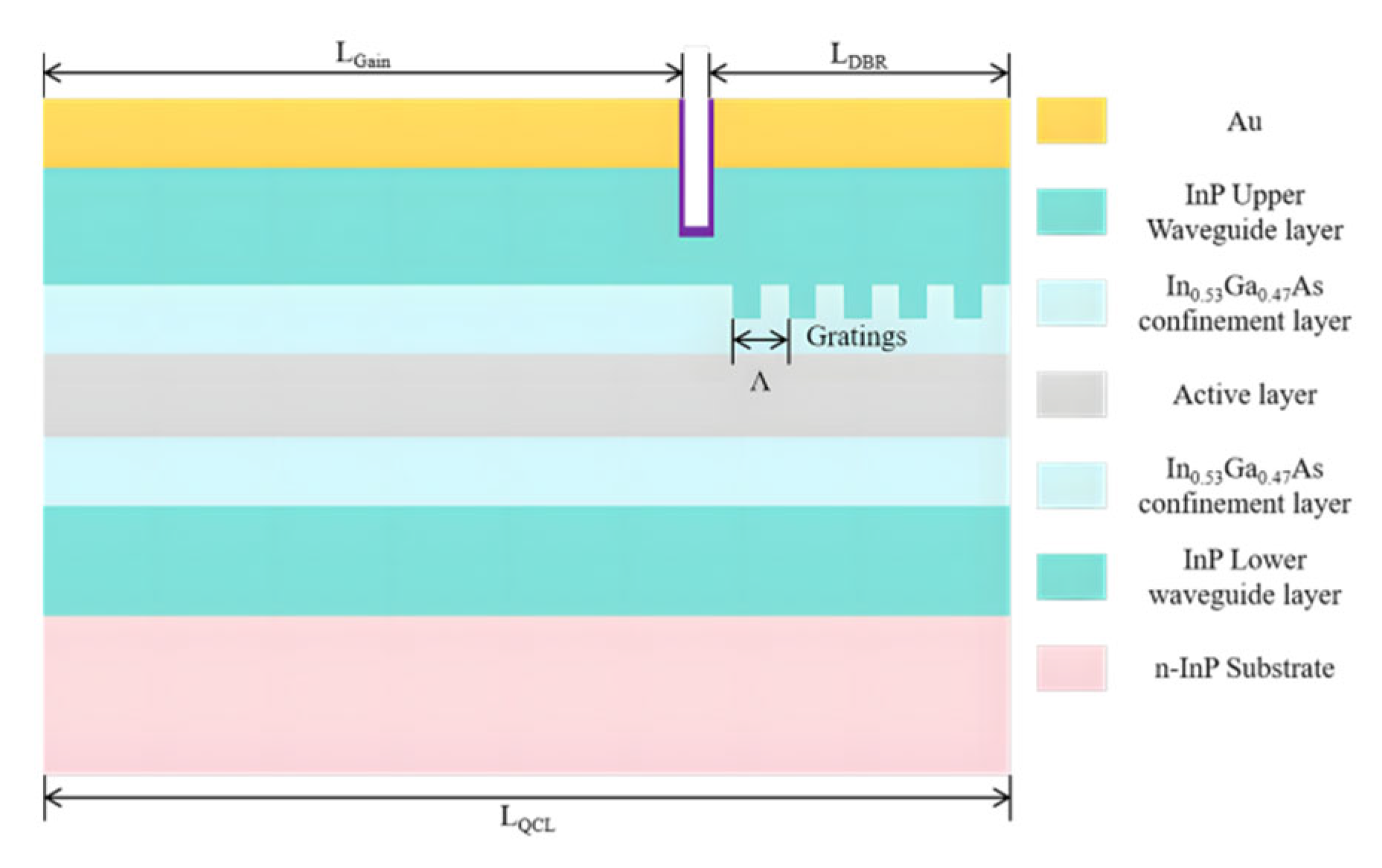
In 2024, the Institute of Semiconductors, Chinese Academy of Sciences, operated QCL at 102 °C in high-temperature continuous-wave mode (current: 1.25 A and microchannel water cooling) using gradient injection layers (carrier efficiency: ↑40%), as shown in Figure 8. It had an output power of 1.18 W (pulse peak), an SMSR of 35.8 dB (λ = 8.4 μm), and a tuning range of 5.23 cm−1 (10–80 °C). The thermal drift is only 0.0078 nm/°C, and the power attenuation is less than 4.2% after 100 h (accelerated aging at 85 °C) [16].

3.4. Beam Control and Mode Optimization

3.4.1. Single-Petal Surface Emission

In 2020, the University of Wisconsin–Madison (UW-Madison) tested asymmetric second-order gratings (duty cycle 0.45) in room-temperature pulse mode (current: 2.5 A and pulse width: 1 μs), as shown in Figure 9. The divergence angle was compressed to 14.6° (E-plane)/12.3° (h-plane), which is 35% lower than the traditional design. It had an output power of 2.17 W (λ = 4.6 μm), an SMSR of 31.7 dB, an edge-mode rejection ratio of ↑43% (spectrometer resolution: 0.5 nm), and a beam ellipticity of 1.14 (M2 = 1.32) [27].
In 2021, NASA’s Jet Propulsion Laboratory (JPL) verified the deharmonic coupler (Δλ = 15.2 nm) at 25 °C in continuous-wave mode (current: 980 mA), and the SMSR increased to 38.3 dB (λ = 8.3 μm), as shown in Figure 10. It had an output power of 81.7 mW, a power fluctuation of ±1.15% (constant current for 24 h), a beam quality of M2 < 1.48, and a side-mode suppression gain of 37.6% [42].

3.4.2. Long-Range Single-Mode Control

In 2023, the University of Electronic Science and Technology of China tested a 3.6 mm long gain region DBR (2.7 THz) at 80 K in low-temperature pulse mode (current density: 115 A/cm2 and pulse width: 500 ns), as shown in Figure 11 and Figure 12. The SMSR is 26.1 dB; the threshold current density is 112 A/cm2 (compared with 110 A/cm2 for the FP cavity), and the output power is 8.7 mW. The spectral linewidth is 4.18 MHz (Fourier transform analysis), while mode stability improved by 52% (10 h drift: <0.01 cm−1) [11].

3.5. System Integration and Application Expansion

3.5.1. Exploration of New Architectures

In 2022, a DBR-VCSEL hybrid chamber (λ = 4.3 μm) was operated in room-temperature pulse mode (current density: 1.82 kA/cm2 and duty cycle: 5%) at the Warsaw University of Technology in Poland, as shown in Figure 13. The threshold current density is 1.79 kA/cm2; the pulse power is 12.3 mW, and the SMSR is 28.5 dB, with a divergence angle of 8.4° (full angle) and a beam circular symmetry of >95% (verified by two-dimensional scans) [41].
In 2022, Nanjing University in China tested the mode–power decoupling structure (3.5 THz) in an 80 K low-temperature environment (current density: 1.1 kA/cm2), as shown in Figure 14. The single-mode extraction efficiency was 32.4% (18.2% traditional); the SMSR was 29.3 dB, and the output power was 11.3 mW (pulse width 1 μs). The spectral drift was < ± 0.021 cm−1 (4 h of continuous operation) [43].

3.5.2. Multi-Scenario Applications

In 2015, Princeton University in the United States achieved simultaneous detection of CH4/N2O/H2O in continuous-wave mode at room temperature (current: 800 mA and TEC temperature control: ±0.1 °C) using SG-DBR tuning technology (based on [16]). The tuning range covered 148.5 cm−1 (1160–1308.5 cm−1), with an output power of 61.2 mW (average), an SMSR of >35 dB (full band), and a detection limit up to the ppb level (CH4: 8.2 ppb and N2O: 11.5 ppb). The signal-to-noise ratio is enhanced to 286:1 by wavelength modulation spectroscopy (WMS), and the temperature drift coefficient is controlled at 0.022 cm−1/°C. This application study was classified as a dual breakthrough of wide tuning technology and multi-scenario application (Section 3.3.1 and Section 3.5.2) to verify the practicality of SG-DBR in complex gas detection for the first time [4].
In 2021, the Institute of Semiconductors, Chinese Academy of Sciences, verified the double shallow etching DBR structure in room-temperature pulse mode (current: 1.8 A and pulse width: 500 ns) through independent electrode electric switching control to achieve dual wavelengths, with a switching speed of < 15 μs, an output power of 85 mW/78 mW (dual-channel), an SMSR of >31 dB (full band) [24].
In 2024, the Institute of Semiconductors, Chinese Academy of Sciences, operating at 102 °C in extreme-high-temperature continuous-wave mode (current: 1.25 A and microchannel water cooling) combined QCL with a gradient carrier injection layer (electro-optic efficiency: ↑38%) to achieve single-mode lasing (λ = 8.4 μm). The output power was 1.18 W (pulse peak), with an SMSR of 35.8 dB and a tuning range of 5.23 cm−1 (10–80 °C). The thermal drift coefficient is 0.0078 nm/°C, and the power attenuation is less than 4.2% after 100 h (accelerated aging at 85 °C) [16].

3.6. Challenges and Future Directions

DBR-QCL technology has made significant progress in recent years, mainly reflected in several key directions.
In terms of mirror design, Babichev et al. used ion beam etching technology to produce DBR, which reduced the sidewall roughness to 8.7 nm, effectively improving the SMSR [32]. Bismuto et al. achieved continuous-wave (CW) single-mode operation with a power consumption of less than 0.87 W by using a super-thin upperguide layer design (1.8 μm) [36].
In terms of wavelength control technology, Mansuripur et al. and Diba et al. utilized SG-DBR to achieve a wide tuning range of more than 156 cm−1 and 148.5 cm−1 [9], respectively. Guan et al. developed a DBR structure that achieved rapid electrical switching (<15 μs) between two wavelengths (8.3 μm and 9.1 μm) [4]. Olariu et al. even demonstrated a wafer post-processing frequency tuning technology [24], achieving a tuning accuracy of 0.11 cm−1.
The high-temperature operation has also been broken through. Radosavljevic et al. used an external Ge-on-SOI DBR to operate continuously in a wide temperature range of 25–85 °C, with a low thermal drift coefficient of 0.009 nm/°C, which is far superior to traditional DBR [19]. Guan et. improved the electro-optic efficiency by 40% through a gradient carrier injection layer design and successfully achieved continuous-wave single-mode lasing (λ~8.4 m) at an extreme high temperature of 102 °C, with an output power of 1.18 W [16].
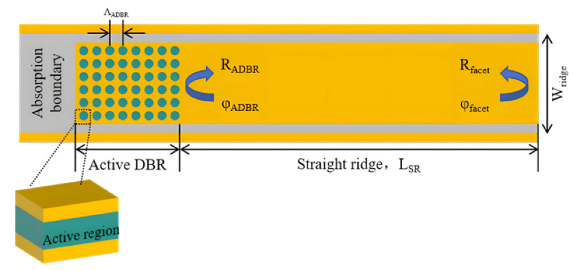
In terms of integration, Janczak et. explored a DBR-VCSEL hybrid cavity structure, which achieved pulse operation at λ = 4.3 μm [41]. Wang et al. proposed a THz ADBR-QCL, which increased the single-mode extraction efficiency to 32.4% (compared to 18.2% conventionally).
However the development of DBR-QCL still faces severe challenges, and the thermal drift problem and large-scale production are the main bottlenecks restricting its widespread application [4].
Monol integration is the key path to solving thermal management and reducing costs. For instance, the Si-bonded DBR realized by Yoshinaga et al. has shown promising prospects, and more intimate heterogeneous integration (such as the III-V/Si photonics integration platform) needs to be explored in the future to achieve compact, robust, and low-cost monol DBR-QCL systems [40].
Table 4 outlines representative recent breakthroughs in DBR-QCL research and DBR-QCL core performance. Progress focuses on low-loss mirrors (e.g., IBE for roughness), enhanced thermal stability (e.g., Ge-on-SOI for low drift), precise wavelength control (e.g., SG-DBR tuning and post-process correction), and beam optimization.

4. Advances in Distributed Feedback (DFB) Single-Mode Quantum Cascade Lasers

4.1. Overview

DFB-QCL development centers on grating innovations (non-rectangular [44] and temperature-compensated [45]), stability breakthroughs (mode-hop suppression [46]), and system integration (dual-wavelength [23] and phased arrays [47]). Recent CMOS-compatible processes [28] and ML design tools [29] drive its evolution toward high-performance, low-cost, and intelligent operation. This chapter analyzes these interconnected technical paths.

4.2. Grating Structure Innovations and Single-Mode Control Mechanisms

4.2.1. Sampling Grating Technology

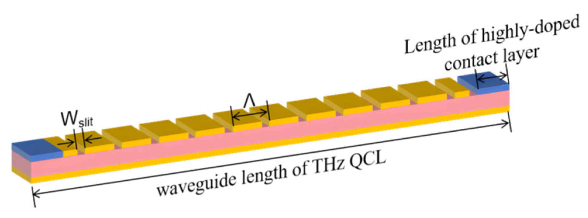
In 2012, Northwestern University in the United States developed a two-segment sampling grating DFB (grating period difference: 0.5%) for overlapping tuning of reflection peaks through independent current injections, as shown in Figure 15. Under 300 K continuous-wave operation, the single-mode tuning range reaches 5.5 cm−1 (λ~4.6 μm); the power is greater than 50 mW; the SMSR is greater than 30 dB; the line width is less than 10 MHz; and the tuning rate is 1 cm−1/ms. The innovation lies in the dual grating electronically controlled tuning mechanism, which breaks through the wavelength tuning range limitations of the traditional DFB [7].
In 2019, the Institute of Semiconductors, Chinese Academy of Sciences, used a 30% duty cycle sampling grating to suppress 3.2 THz side modes by using the superposition effect of reflection peaks in sub-grating groups. Under a 10 K pulse operation (pulse width: 500 ns), the single-mode output power is 18 mW; the SMSR is >25 dB; wavelength temperature stability is 0.02 cm−1/K (10–80 K); and the threshold current density is 0.14 kA/cm2. The innovation lies in the sampling grating enhancing the mode interval in the terahertz band and improving single-mode selectivity. This work directly addresses the mode competition problem of terahertz QCL through grating parameter optimization (duty cycle) [48].
In 2020, the Institute of Semiconductors, Chinese Academy of Sciences, combined conical waveguides with gradually changing periodic sampling gratings to regulate the light field distribution and suppress high-order modes, achieving a coordinated improvement in power and beam quality, as shown in Figure 16. Under the 288 K pulse condition (pulse width: 1 μs and repetition frequency: 100 kHz), the single-mode power reaches 1.2 W (cavity length 3 mm); the SMSR is >35 dB; the vertical divergence angle is compressed to 4.7° (traditional devices > 10°); the beam quality factor is M2 = 1.8; and the threshold current density is 1.1 kA/cm2. The innovation lies in the grating gradient period design and the matching of waveguide broadening, resolving the contradiction between high power and low divergence angles [37].
In 2022, the Institute of Semiconductors, Chinese Academy of Sciences, designed a sampling grating with a period gradient (0.5%) along the cavity length direction to expand the mode interval through the Vernier effect and to lock the terahertz single mode, as shown in Figure 17. Under a 50 K continuous-wave operation, the output power of 5.1 THz is 3.2 mW, with an SMSR of >30 dB. There is no mode skipping within the temperature range of 10–100 K (current 0.8–1.5 A), and the tuning range is 8 GHz (current scanning). The innovation lies in the dynamic temperature drift compensation mechanism, which addresses the instability of the low-temperature operating mode [45].

4.2.2. Surface Emission Structures

In 2018, Nanjing University in China combined second-order and fourth-order Bragg gratings to enhance the vertical radiation intensity and surface emission efficiency, as shown in Figure 18. Under the 80 K pulse operation, the output power is 52 mW; the SMSR is 27 dB; and the surface emission efficiency is 35% higher than that of a pure second-order grating (test conditions: current density: 0.23 kA/cm2). The mixed-order design enhances the intensity of the vertical component light field through multi-level diffraction coupling. This work is classified as a surface emission grating design. The innovation lies in the hybrid optimization of grating orders, which directly resolves the power-efficiency contradiction of terahertz surface emission [49].
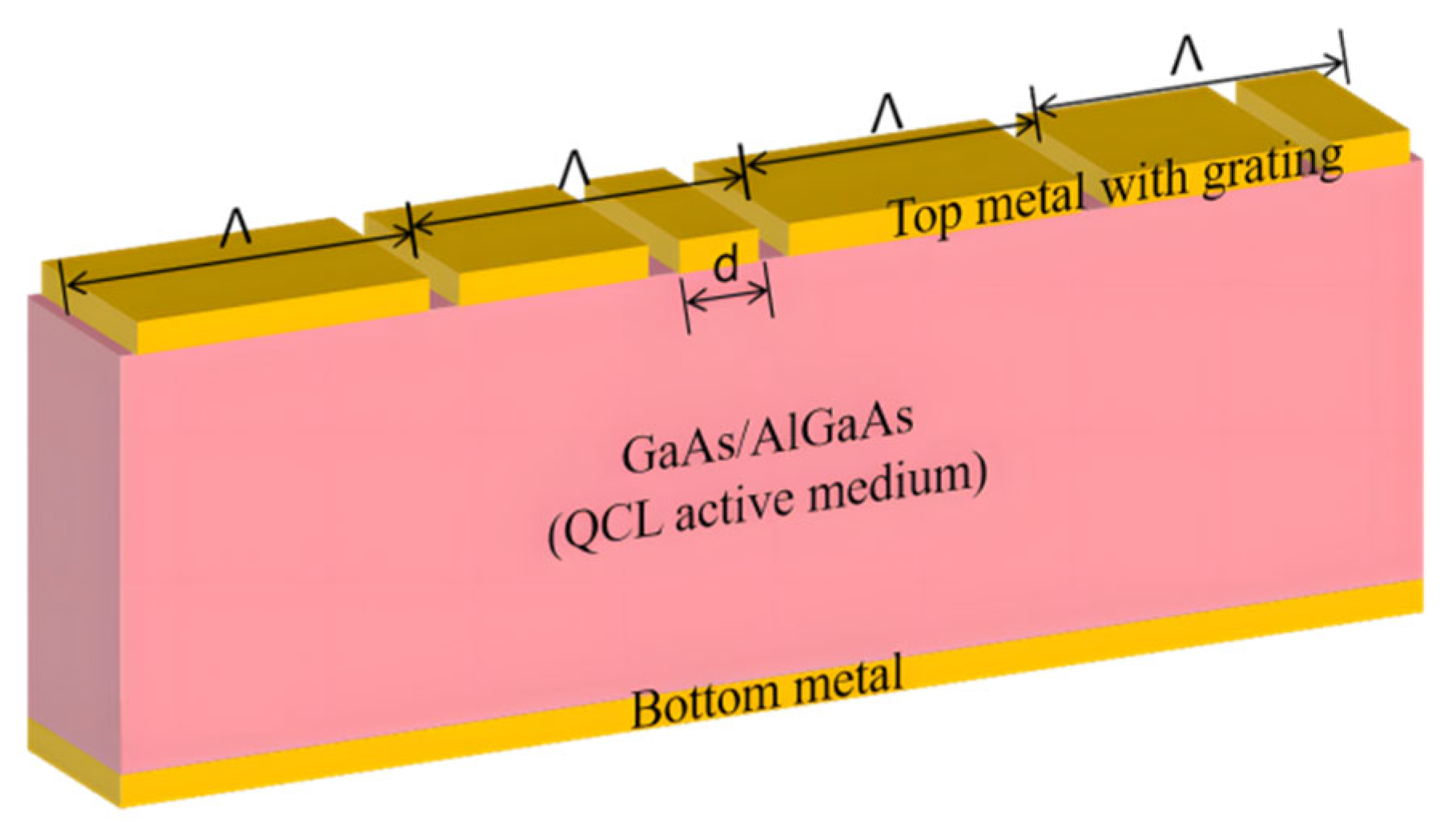
In 2024, a research team from the Institute of Semiconductors, Chinese Academy of Sciences realized low-divergence-angle terahertz surface emission through innovative integration of a multimode interferometer (MMI), as an alternative to conventional end-face reflection approaches, as shown in Figure 19. At a 80 K continuous wave operation (current density: 0.25 kA/cm2), the output power is 8.5 mW; the SMSR is 26 dB; and the beam quality factor is M2 = 1.6 (divergence angle: <5°). The innovation lies in the MMI structure that converts multi-transverse mode interference into a single collimated beam without the need for an external lens. The core technology is to optimize the spatial light field distribution through built-in optical devices, directly enhancing the directionality of radiation [50].
In 2025, the Institute of Semiconductors, Chinese Academy of Sciences, achieved high radiation-efficiency terahertz surface emissions by breaking the traditional grating periodic symmetry and optimizing the scattering efficiency and mode coupling strength, as shown in Figure 20. Under the 78 K pulse operation (pulse width 1 μs), with an output power of 45 mW and an SMSR of >28 dB, the radiation efficiency is 50% higher than that of traditional gratings (test conditions: current density: ~0.22 kA/cm2). Breaking the periodic structure enhances the resonant mode selectivity of the grating and reduces unwanted scattering loss [51].

4.2.3. Annular Cavity Single-Mode Control

In 2023, the Swiss Federal Institute of Technology Zurich (ETH Zurich) proposed a ring grating cavity structure to achieve radial radiation and high-order mode suppression, solving the random phase interference problem of the traditional edge-emitting DFB-QCL. Under the 300 K pulse operation (pulse width not disclosed and repetition frequency: 100 kHz), the single-mode output power is 65 mW; the SMSR is >30 dB; the radial divergence angle is compressed to <3° (traditional devices: >10°); and the threshold current density is 0.75 kA/cm2. Its ring grating design homogenizes the electric field distribution and significantly improves beam quality. The essence of the innovation lies in regulating the light field distribution through the annular cavity spatial structure [26].

4.3. Single-Mode Stability Enhancement Techniques

4.3.1. Anti-Mode Jump Design

In 2018, the Institute of Semiconductors, Chinese Academy of Sciences, used Al2O3/Ge bilayer anti-reflection coatings to reduce the cavity surface reflectance to 0.1%, significantly suppressing the competition in the high-temperature mode. Under a continuous wave operation at 90 °C (current: 0.65 kA/cm2), the SMSR remains above 26 dB, with an output power of 170 mW (λ = 4.6 μm), and the mode-jumping temperature range is extended to 20–90 °C. The anti-reflection film weakens the phase interference of random reflection at the end face to the DFB mode, enhancing high-temperature stability [52].
In 2023, Huazhong University of Science and Technology, China, innovatively integrated distributed grating reflectors on the cavity surface instead of traditional coatings to suppress mode competition at high injection currents through a feedback phase locking mechanism. Under the operating condition at 300 K in continuous-wave mode (current: 1.5× and threshold current: 380 mA), the device’s output power reaches 210 mW, the side-mode rejection ratio (SMSR) remains above 25 dB, the power fluctuation is less than 5% (0–100 mA square wave modulation test), and the upper limit of power without mode skipping is 40% higher than that of the traditional design. The core breakthrough lies in the fact that the grating reflector eliminates the phase noise caused by random reflection at the end face, solving the mode instability under high power drive using a physical mechanism [46].

4.3.2. Stability Under Extreme Conditions

In 2020, the Institute of Semiconductors of the Chinese Academy of Sciences proposed a composite structure of conical waveguides and sampling gratings. By gradually regulating the light field distribution along the waveguide broadening direction with the grating period, the power and beam quality can be optimized in a coordinated manner. Under the operating condition of 288 K pulses (pulse width: 1 μs and repetition frequency: 100 kHz), the single-mode power reaches 1.2 W (cavity length: 3 mm), the SMSR reaches > 35 dB, the vertical divergence angle is compressed to 4.7° (traditional devices > 10°), the beam quality factor is M2 = 1.8, and the threshold current density is 1.1 kA/cm2. The innovation lies in the gradient period design of the sampling grating to enhance fundamental mode selectivity and the conical waveguide to suppress higher-order transverse modes [37].
In 2022, the Institute of Semiconductors, Chinese Academy of Sciences, significantly enhanced high-temperature single-mode stability through the co-design of the strain-compensated InGaAs/InAlAs active region with the λ/4 phase-shifted grating (coupling coefficient: κ = 12 cm−1). Under the continuous-wave operation in a wide temperature range of 20–90 °C (current: 0.6–1.1 A), the device outputs a power of 170 mW (wavelength 6.12 μm), with an SMSR of >26 dB, a characteristic temperature of T0 = 210 K, and a line width of 1.2 MHz (1 s integral). The innovation lies in the matching optimization of grating parameters with active region strain engineering to suppress mode transitions caused by high-temperature carrier leakage [39].

4.3.3. Narrow Line Width Assurance

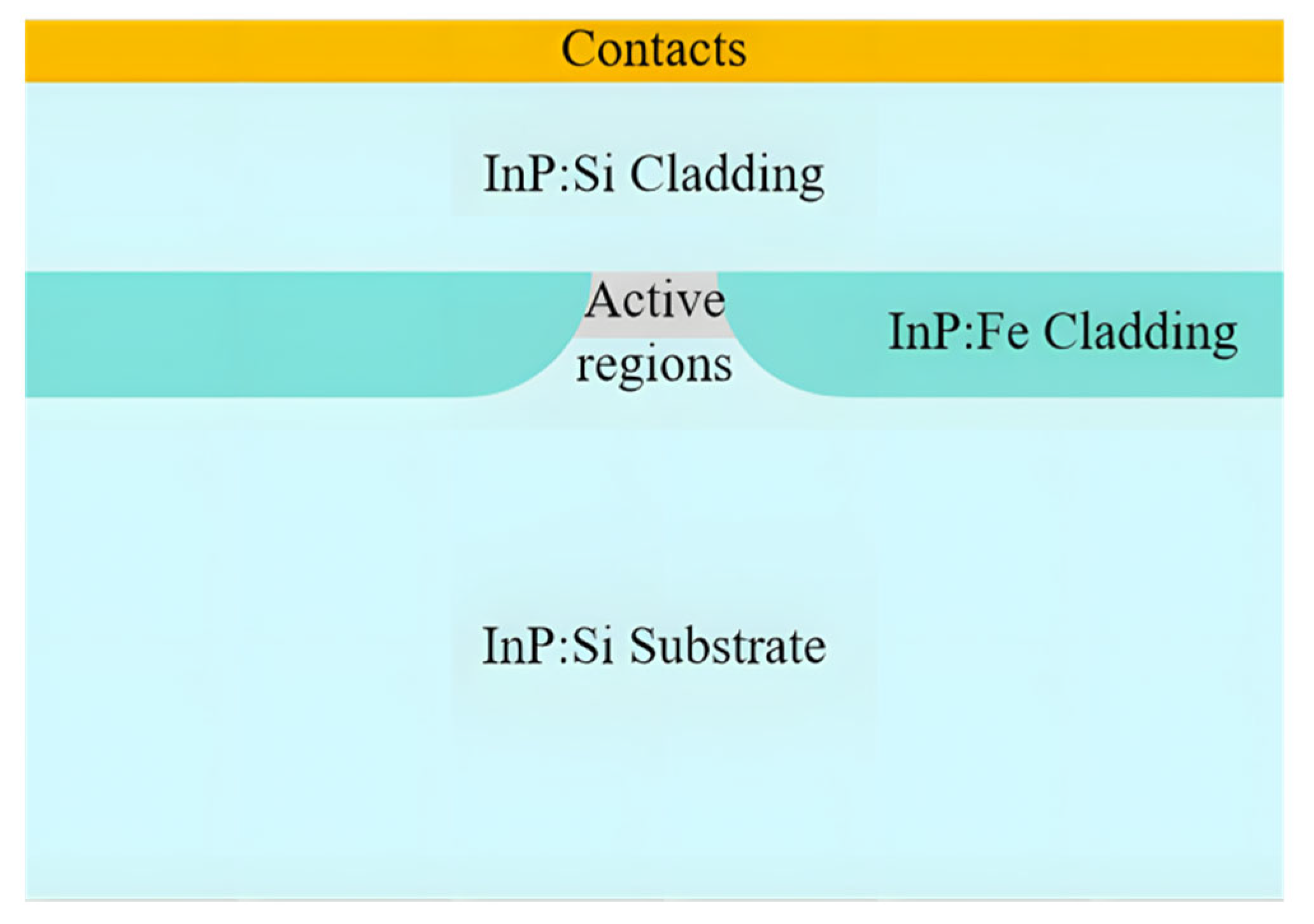
In 2022, the Swiss Federal Institute of Technology Zurich (ETH Zurich) designed subwavelength high-impedance gratings (period: 300 nm) combined with low-noise driver circuits to suppress frequency noise caused by carrier density fluctuations, as shown in Figure 21. Under the continuous-wave operation at 298 K, the output power is 108 mW, the SMSR is greater than 32 dB, the line width voltage is narrowed to 10 kHz (1 ms integration time), the temperature drift coefficient is 0.25 cm−1/K (20–50 °C), and the resolution in NH3 spectral detection reaches 0.001 cm−1. The innovation lies in the subwavelength grating enhancing mode discrimination while the low-noise drive suppresses electrical noise [5].

4.4. Advanced Manufacturing Process

4.4.1. Breakthroughs in Wafer-Level Mass Production

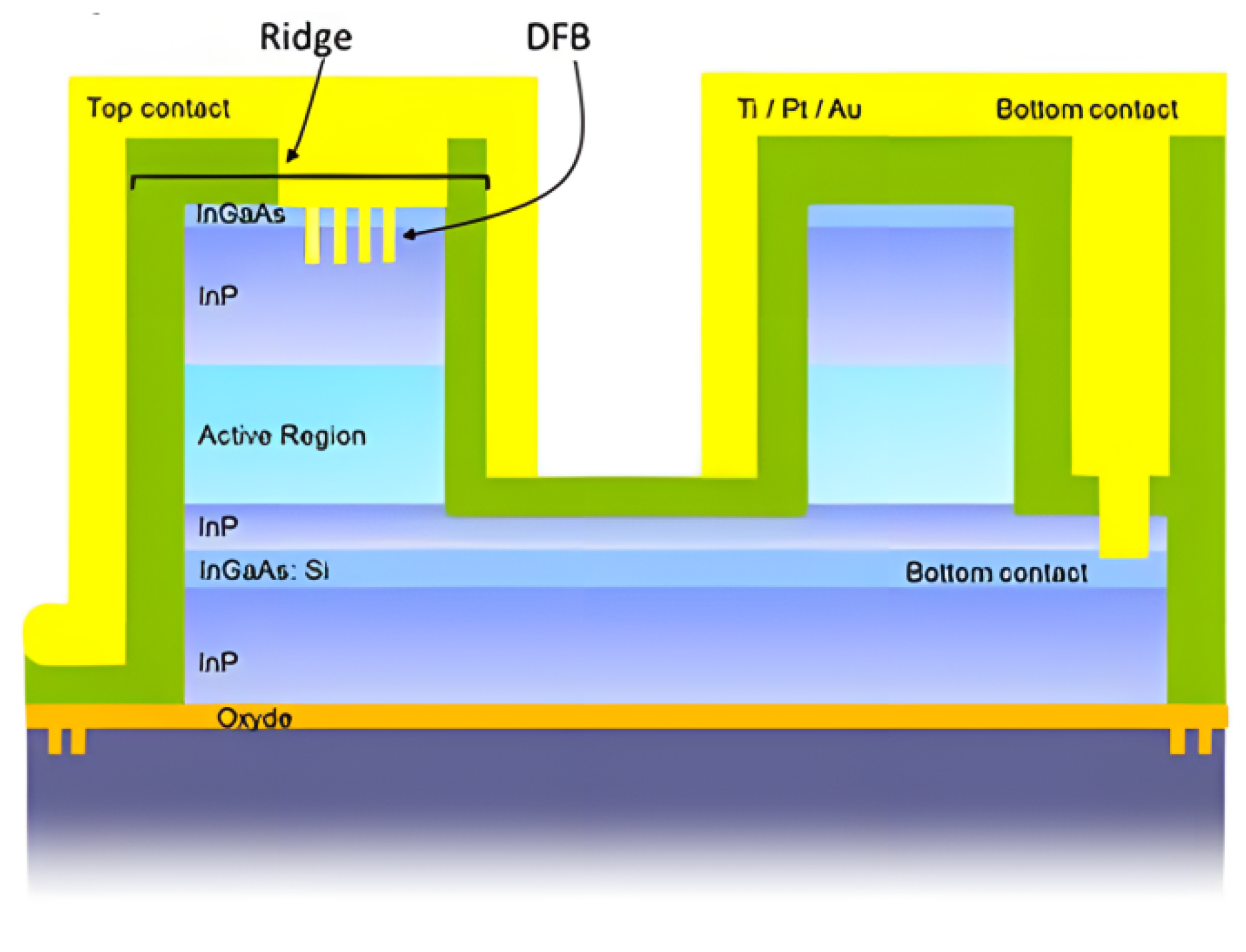
In 2020, at the CEA-Leti Institute in France, the study achieved wafer-level mass production of DFB-QCL on a 200 mm CMOS process line for the first time, as shown in Figure 22, using deep ultraviolet lithography to fabricate sub-micron gratings, significantly reducing manufacturing costs. The innovation lies in using deep ultraviolet lithography instead of electron beam lithography to achieve high consistency batch production of grating structures. Under the 300 K continuous wave operating condition (current not disclosed), the output power of the single-stripe chip reaches 150 mW (wavelength: 4.6 μm), the side-mode rejection ratio (SMSR) is greater than 25 dB, and the threshold current density is 1.15 kA/cm2, with a wafer yield of >85%, wavelength uniformity controlled within ±0.8 nm (128 device statistics), and a threshold current discretization of <5%. The core breakthrough is the large-scale fabrication of grating structures through a mature semiconductor industry platform [28].

4.4.2. Machine Learning-Assisted Design

In 2021, Zhejiang University in China proposed a terahertz DFB-QCL resonant mode prediction model based on deep neural networks, as shown in Figure 23, which takes grating period, depth, duty cycle as the input and directly outputs the resonant frequency and the Q-value instead of traditional time-consuming 3D simulations. The innovation lies in the introduction of machine learning into the grating design process, which solves the bottleneck of complex calculations and long cycles (typically 72 h) of traditional finite element analysis. In the experimental verification, for the 3.5 THz device operating at 80 K pulses (pulse width not disclosed), the measured SMSR was greater than 25 dB, the output power was 25 mW, and the threshold current density was 0.20 kA/cm2 [29].
In 2024, researchers from Northwestern University constructed a dataset containing 150,000 groups of active region parameters and developed an automatic identification algorithm for wave functions. The algorithm’s recognition accuracy exceeds 98%, which has increased the gain coefficient of quantum cascade lasers by 22%, and the quantum efficiency has leaped to 75%. In a high-temperature environment of 400 Kelvin, the threshold current density of the device has been reduced by 5%, and the design cycle has been compressed from several months to several hours using traditional methods. This machine learning-driven design paradigm has significantly improved the stability of high-temperature single-mode output and energy utilization efficiency [53].

4.5. Application of Single-Mode System Integration

4.5.1. Multi-Wavelength Single-Mode Integration

In 2016, the team at the U.S. National Institute of Standards and Technology (NIST) achieved the first heterogeneous integration of distributed feedback cascade lasers on a silicon substrate, with the operating wavelength located in the mid-infrared 4.6-micron band. Under room-temperature continuous-wave conditions, the device achieved a current density of 3.1 kiloamperes per square centimeter, with a side-mode suppression ratio as high as 30 decibels and a maximum power of 56 milliwatts. Its innovation lies in the use of III-V materials and silicon waveguide coupling structures, which can control the waveguide coupling loss within 3 decibels, breaking through the lattice mismatch limitations of traditional materials [54].
In 2016, the Swiss Federal Institute of Technology Zurich (ETH Zurich) proposed a spatial isolation scheme by combining double independent grating regions with Y-shaped waveguides to achieve synchronous detection of CH41 = 7.85 μm) and N2O (λ2 = 7.73 μm). Under the operation of 298 K at continuous-wave mode (current density: 0.82 kA/cm2), the power of both channels is greater than 12 mW, the SMSR is greater than 30 dB, the channel crosstalk is less than −35 dB, and the detection limit reaches the ppb level (1 s integral). The Y-shaped waveguide combines the dual-grating output beams with low loss to avoid mode competition. The innovation lies in the spatial isolation of the light field in the waveguide structure [55].
In 2018, ETH Zurich, Switzerland, designed a two-stage distributed feedback (DFB) structure to achieve monolithic integrated dual-wavelength output by matching the absorption peaks of NO and CO21 = 5.26 μm and λ2 = 5.18 μm) through the grating period difference, as shown in Figure 24. Under the room-temperature pulse operation conditions (300 K, with current not disclosed), the dual-channel output power is greater than 15 mW, the side-mode rejection ratio (SMSR) is greater than 28 dB, the line width is less than 20 MHz, and the dual-wavelength difference stability is less than 0.03 cm−1/K [56].
In 2023, the Institute of Semiconductors, Chinese Academy of Sciences, achieved dual-wavelength dynamic switching and hybrid output by integrating a single-chip dual λ/4 phase-shifted grating region (with a spacing of 50 μm) in combination with independent current injection control. Under 300 K continuous-wave operation conditions, as shown in Figure 25, the output power is 25 mW when λ1 = 4.65 μm and 22 mW when λ2 = 4.82 μm. The SMSR is greater than 30 dB; the wavelength switching time is less than 100 ns, and the dual-wavelength mixed linewidth is less than 15 MHz. The innovation lies in the electrically controlled fast switching mechanism of the dual-grating region, which supports real-time multi-component analysis [23].

4.5.2. Single-Mode Array and Beam Control

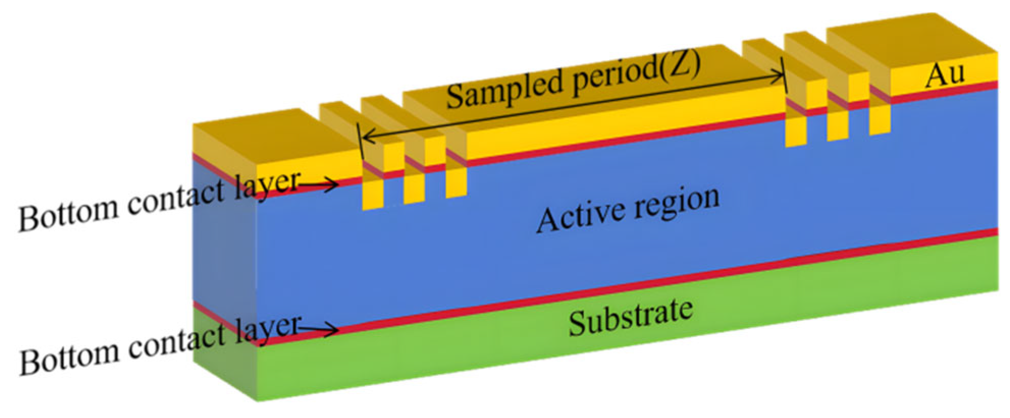
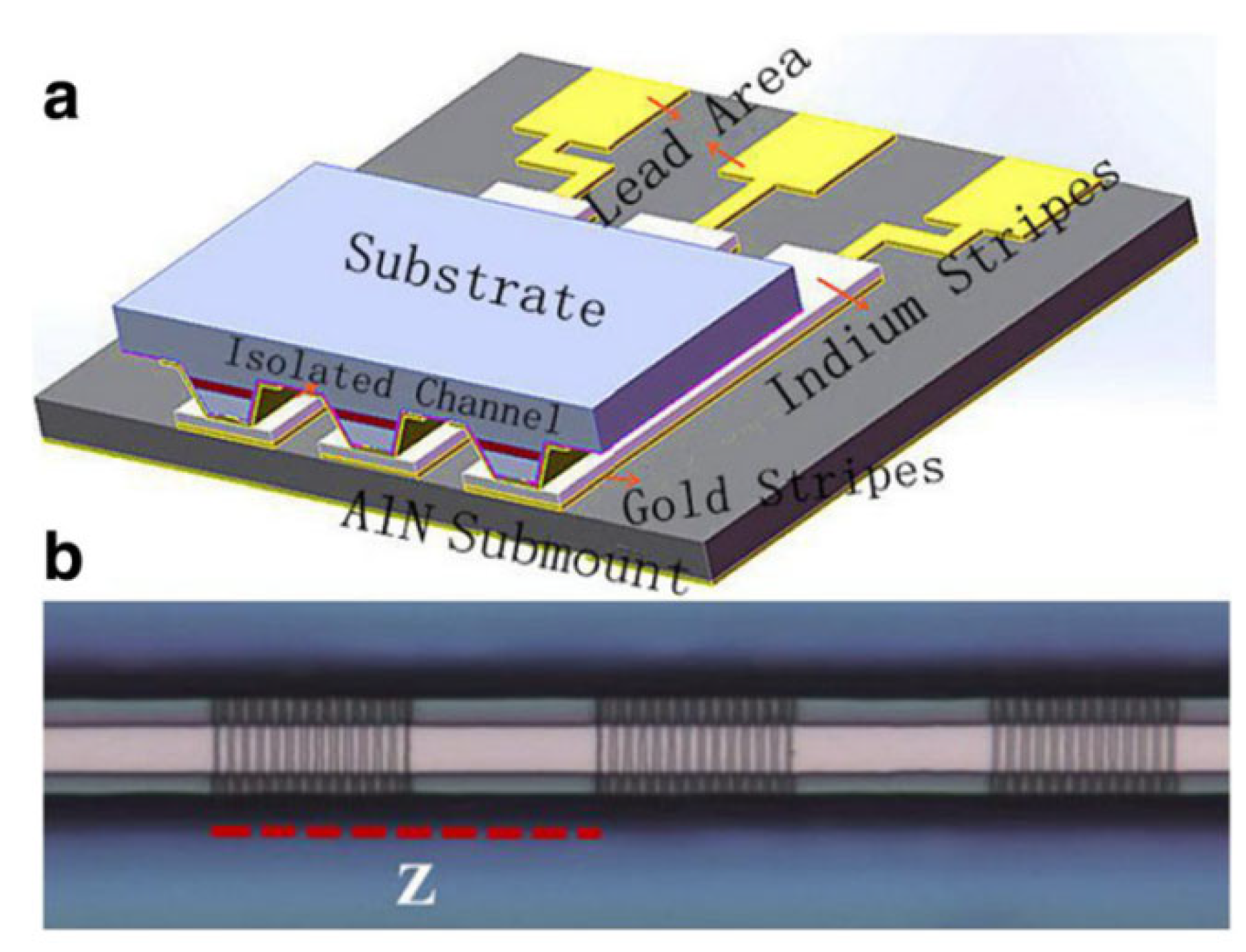
In 2015, the Institute of Semiconductors, Chinese Academy of Sciences, prepared a 16-cell DFB array using a uniform sampling grating template (number of sub-gratings = 8) and controlled the cell wavelength consistency by fine-tuning the sampling period, as shown in Figure 26. Under the operation at 288 K in continuous-wave mode (current density: 1.05 kA/cm2), the total power of the array reaches 1.5 W, the wavelength deviation of the units is less than 0.02 μm (center λ = 4.55 μm), the SMSR is greater than 25 dB, and the crosstalk between units is less than −40 dB. The innovation lies in the batch design of the grating template, which enables wavelength uniformity control for high-density arrays.
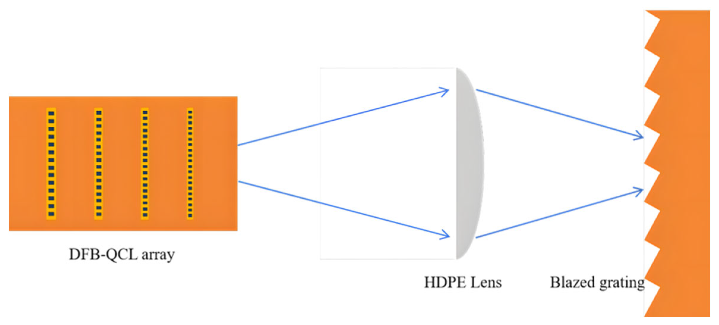
In 2021, Nanjing University in China adopted the current tuning mechanism of multi-unit DFB arrays to achieve wideband spectral synthesis and scanning functions, as shown in Figure 27. Under the 78 K pulse operation (pulse width: 500 ns), the total power of the four-element array is 110 mW, the SMSR is >25 dB, the tuning range reaches 0.2 THz (3.9–4.1 THz), and the phase error is less than λ/10 (test condition: single-mode threshold current density: 0.19 kA/cm2). Independent wavelength control per unit with subsequent synthesis eliminated the single-mode spectrum constraints. The core technology is to achieve wide-spectrum scanning through an electrically controlled array [38].
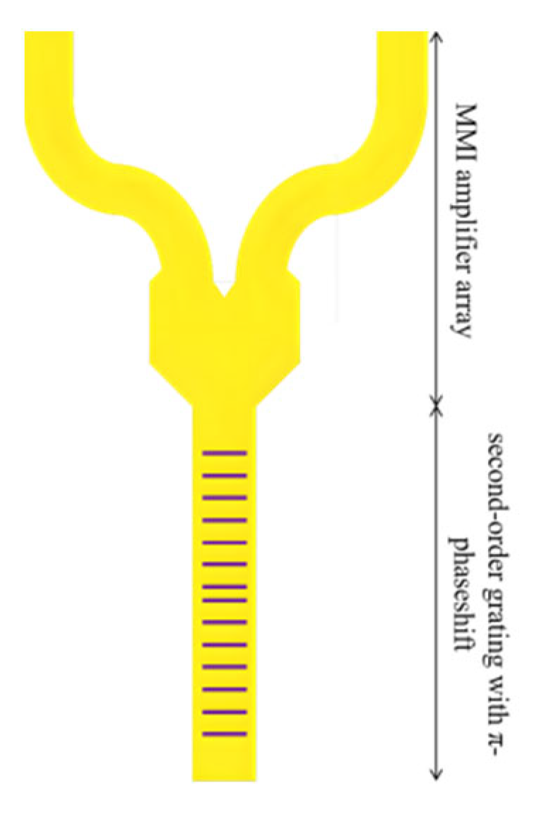
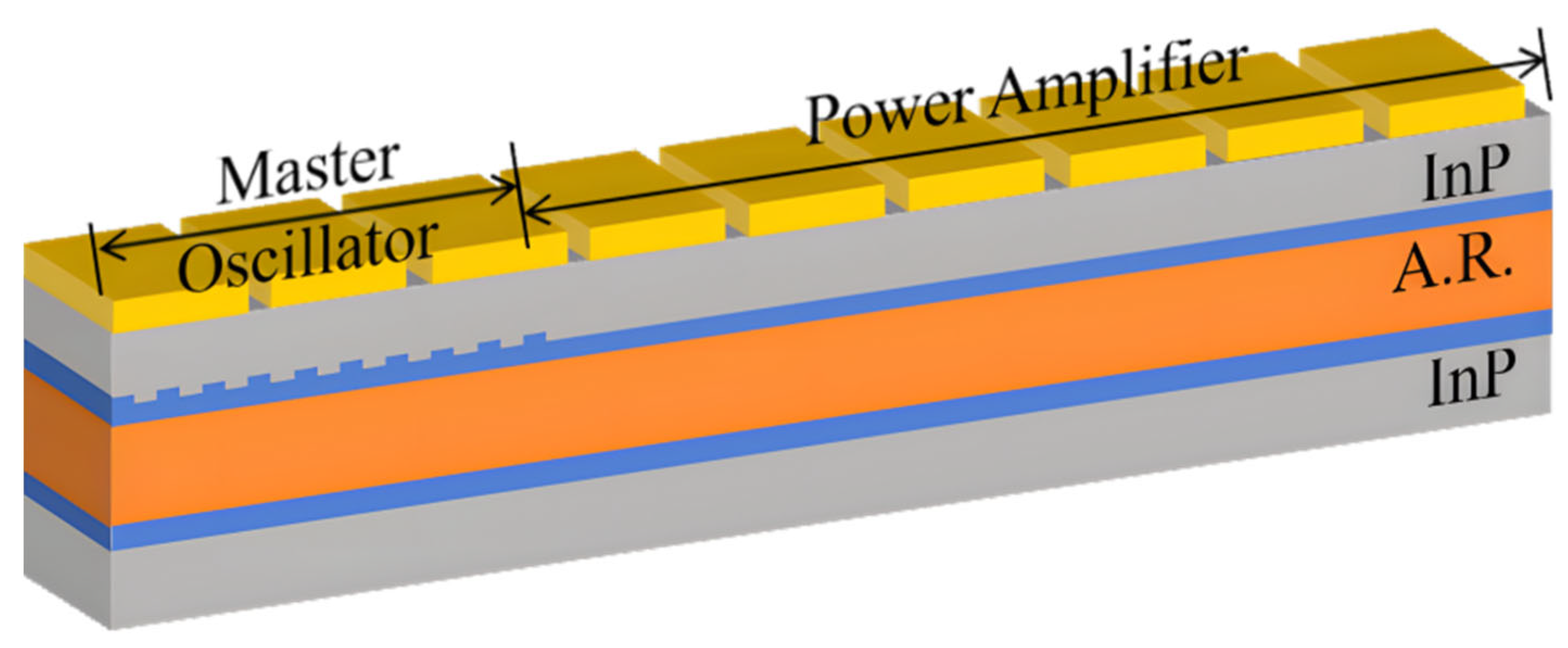
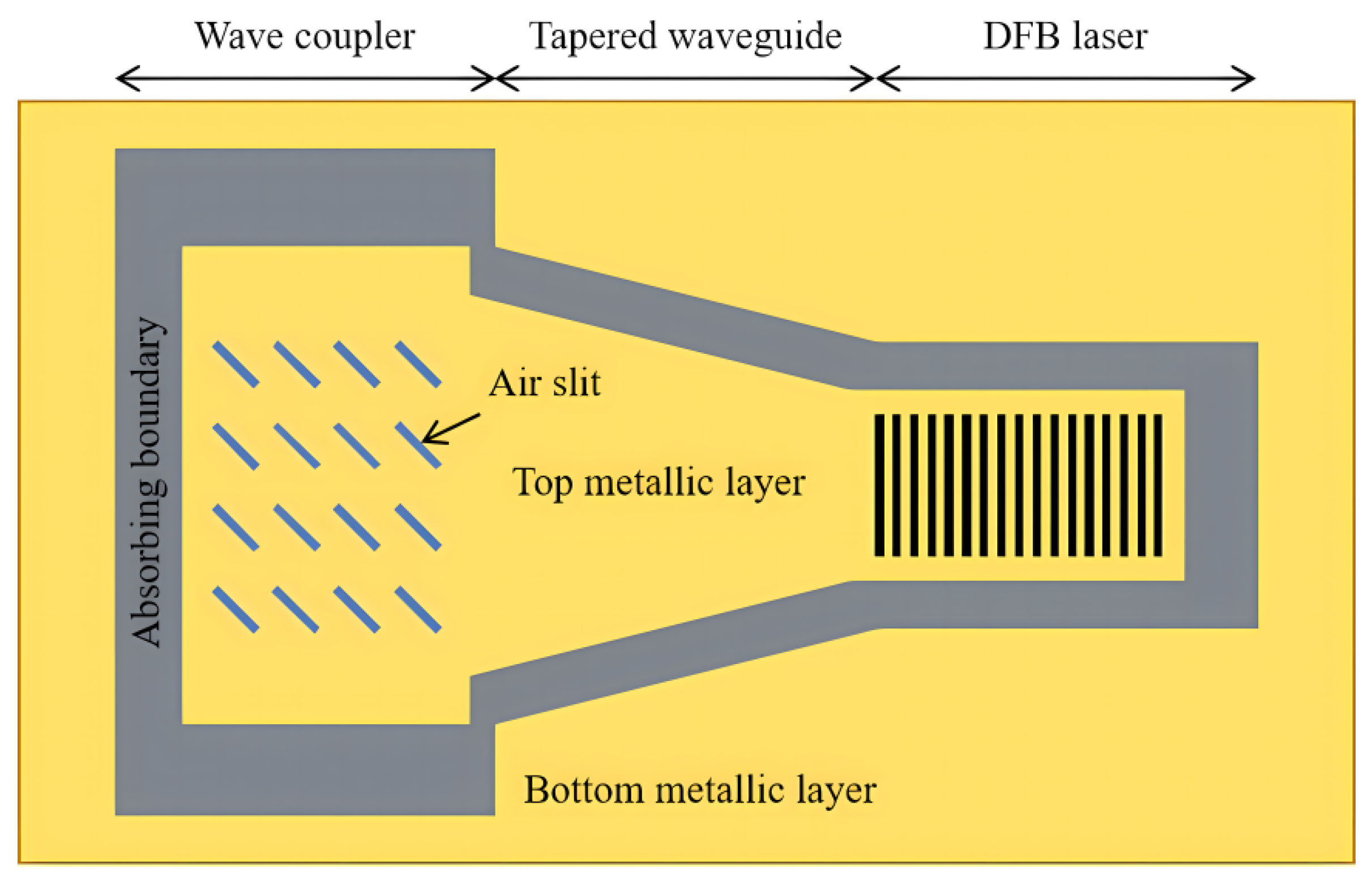
In 2022, the University of Electronic Science and Technology of China integrated a two-dimensional metal grating into the terahertz master oscillator-power amplifier (MOPA) structure, as shown in Figure 28. By injecting current in different zones to regulate the phase of the surface plasma, it achieved two-dimensional electronically controlled beam scanning. Under the 78 K pulse operation (pulse width: 1 μs, 3.5 THz), the peak power is 120 mW, the SMSR is 28 dB, the scanning range is between ±30° (azimuth) and ±15° (pitch angle), and the divergence angle is 5.8°. The innovation lies in the co-design of grating geometry and current partitioning [58].
In 2024, the Institute of Semiconductors, Chinese Academy of Sciences, integrated λ/4 phase-shifted gratings into an eight-cell DFB array to achieve coherent synthesis and directional emission of terahertz beams through electronic phase control, as shown in Figure 29. Under the 78 K pulse operation (pulse width: 1 μs and current density: 0.16 kA/cm2), the total power output of 3.8 THz is 185 mW, the SMSR is 28 dB, the phase error is <λ/10, the beam quality factor is M2 = 1.4, and the divergence angle is 5.2°. The innovation lies in the zero-aberration locking mechanism of the phase-shifted grating, which replaces the complex external optical system [47].

4.5.3. Emerging Application Scenarios

In 2024, the Institute of Semiconductors, Chinese Academy of Sciences, integrated multimode interferometer (MMI) to replace end face reflection and optimize beam directivity and spatial coherence. Under the 80 K continuous wave operation, the output power is 8.5 mW, the SMSR is 26 dB, and the beam quality factor is M2 = 1.6 (test conditions: current: 0.25 kA/cm2 and detector distance: 30 cm). The MMI structure reduces multi-transverse mode interference to a single collimated beam, with the vertical divergence angle reduced to less than 5°. The innovation lies in achieving collimation output without external lenses through the built-in MMI [50].
In 2024, the semi-supervised machine learning framework proposed by the Indian Institute of Technology reduced the demand for labeled data. By achieving a 12 dB signal-to-noise ratio improvement in the 3 to 5 micrometer mid-infrared band, the detection sensitivity reached a level of billionth concentration. The system’s real-time processing latency was less than 100 milliseconds, covering a spectral range from 3 to 12 micromers, and it was successfully applied to the precise monitoring of gases such as methane and carbon dioxide. This technology provides a breakthrough solution for high-precision laser spectroscopy detection in industrial sites [59].
In 2025, UW-Madison developed a DFB-QCL for high-speed free-space communication by optimizing grating geometry for low phase noise, as shown in Figure 30. Operating at 300 K CW, it achieved an output power of 80 mW, an SMSR of >25 dB, and a modulation bandwidth of 1.2 GHz under tightly controlled thermal conditions (±0.1 °C heat sink) [35].

4.6. Summaries and Challenges

In recent years, DFB-QCL has made significant progress, mainly reflected in several key directions. In terms of grating design, the non-periodic grating design proposed by Niu et al. increased the radiation efficiency of terahertz surface emission by 50% to traditional gratings [51]. The hybrid second-/fourth-order Bragg grating developed by Jin et al. achieved a 35% improvement in surface emission efficiency [49]. Ivken et al. pioneered a two-section sampling grating design, which achieved a tuning range of 5.5 cm−1 under continuous wave (CW) [7].
In terms of stability enhancement, Cheng et al. used strain-compensated InGaAs/InAlAs active regions with λ/4 phase-shifted gratings to the single-mode working temperature zone to 20–90 °C (ΔT = 70 °C) [39]. Bertrand et al. combined a subwavelength grating and a low-noise driving circuit to narrow the linewidth of DFB-QCL to 10 kHz (1 ms integration time) [5].
In the of system integration, Yan et al., prepared a 16-element DFB array using a uniform sampling grating template, achieving a unit wavelength consistency of less than 0.2 μm [57]. Xu et al. integrated a λ/4 phase-shifted grating into an eight-element DFB array, and coherent synthesis of terahertz beams (3.8 THz) was realized through electronic locking [47]. The double-grating Y-type waveguide structure designed by Süess et al. successfully realized the spatial isolation dual-wavelength output, with channel crosstalk below −35 dB [55].
Despite remarkable achievements, DFB-QCL still faces ongoing challenges. Thermal dissipation is a critical bottleneck for industrialization. In addition, maintaining high single-mode purity and a high side-mode suppression ratio while pursuing higher output power and balancing narrow linewidth with modulation bandwidth remains a core design challenge.
Future research will focus on heterogeneous integration combined with machine learning tuning. Spott et al. have shown the potential of heterogeneous integration DFB-QCL on a silicon substrate, and in the future, the integration of the silicon-based photonics platform with the QCL active region needs to be deepened to achieve more compact and powerful chip-scale systems [29].
Table 5 summarizes key DFB-QCL advances in grating innovation, stability, fabrication, and system integration. Innovative gratings (non-rectangular, SG, tapered + SG, hybrid-order, and ring) enhance performance (power, beam, tuning, and stability). Fabrication breakthroughs (200 mm CMOS [28] and an ML design [29]) enable mass production. Array [47,57] and dual-wavelength [23,56] integration expands applications. High-T stability [39] and narrow linewidth [5] are significantly improved.

5. Summary and Outlook

5.1. Technological Paradigm Shifts

Single-mode QCL technology is undergoing a paradigm shift from passive adaptation to active regulation. DBR-QCL has been upgraded from the traditional “mirror design” to “gain-reflection spectrum co-engineering”: by optimizing the matching degree between the DBR reflection peak and the gain spectrum, continuous single-mode operation at 102 °C was achieved in 2024 [16]. DFB-QCL shifted from experience-driven grating etching to an “AI-manufacturing closed loop”: machine learning algorithms could predict resonant mode characteristics with an error of less than 3% [29], and combined with digital stitching grating technology, the tuning range was extended to 880 GHz [37].

5.2. Reconfiguration of Application Scenarios

Single-mode QCLs advance from point detection to all-domain sensing. Environmental monitoring uses terahertz arrays [47] and multi-wavelength arrays [57] for 3D pollutant mapping (CH4/N2O/CO2, 10 m × 10 m × 5 m resolution) at 100× efficiency [4]. Deep-space communication leverages the 4.7 μm atmospheric window (<0.3 dB/km Mars loss [35]), enabling 10 Gbps Earth–Mars links (BER < 10−12). Clinical diagnostics employs dual-wavelength on-chip integration [24] for 5 min diabetic risk assessments.

Author Contributions

Conceptualization, J.Z. and Y.Q.; methodology, D.X.; software, C.Z.; validation, D.X.; formal analysis, M.Y.; investigation, J.Z. and Q.W.; resources, Y.Q.; data curation, J.Z. and Y.L.; writing—original draft preparation, J.Z.; writing—review and editing, D.X.; visualization, M.Y.; supervision, Y.Q.; project administration, Y.Q.; funding acquisition, D.X. All authors have read and agreed to the published version of the manuscript.

Funding

This work was supported by the Open Fund for Innovation and Entrepreneurship of College Students of Hainan Normal University (Nos. RSYH20231165818X and RSXH20231165809X), and the National Natural Science Foundation of China (Nos. 62274048, 62064004, and 62174046).

Data Availability Statement

The original contributions presented in this study are included in this article. Further inquiries can be directed to the corresponding author.

Conflicts of Interest

The authors declare no conflicts of interest.

References

  1. Faist, J.; Capasso, F.; Sivco, D.L.; Sirtori, C.; Hutchinson, A.L.; Cho, A.Y. Quantum cascade laser. Science 1994, 264, 553–556. [Google Scholar] [CrossRef] [PubMed]
  2. Lu, Q.Y.; Bai, Y.; Bandyopadhyay, N.; Slivken, S.; Razeghi, M. Room-temperature continuous wave operation of distributed feedback quantum cascade lasers with watt-level power output. Appl. Phys. Lett. 2010, 97, 231119. [Google Scholar] [CrossRef]
  3. Lu, Q.Y.; Bai, Y.; Bandyopadhyay, N.; Slivken, S.; Razeghi, M. 2.4 W room temperature continuous wave operation of distributed feedback quantum cascade lasers. Appl. Phys. Lett. 2011, 98, 181106. [Google Scholar] [CrossRef]
  4. Diba, A.S.; Xie, F.; Gross, B.; Lu, W.; Caneau, C.; Visovsky, N.J.; Phillips, M.C.; Gluszek, A.; Hudzikowski, A.; Weidmann, D. Application of a broadly tunable SG-DBR QCL for multi-species trace gas spectroscopy. Opt. Express 2015, 23, 27123–27133. [Google Scholar] [CrossRef]
  5. Bertrand, M.; Shlykov, A.; Shahmohamadi, M.; Beck, M.; Willitsch, S.; Faist, J. High-power, narrow-linewidth distributed-feedback quantum-cascade laser for molecular spectroscopy. Photonics 2022, 9, 589. [Google Scholar] [CrossRef]
  6. Bismuto, A.; Blaser, S.; Terazzi, R.; Gresch, T.; Muller, A. High performance, low dissipation quantum cascade lasers across the mid-IR range. Opt. Express 2015, 23, 5477–5484. [Google Scholar] [CrossRef]
  7. Slivken, S.; Bandyopadhyay, N.; Tsao, S.; Nida, S.; Bai, Y.; Lu, Q.Y.; Razeghi, M. Sampled grating, distributed feedback quantum cascade lasers with broad tunability and continuous operation at room temperature. Appl. Phys. Lett. 2012, 100, 261112. [Google Scholar] [CrossRef]
  8. Slivken, S.; Bandyopadhyay, N.; Bai, Y.; Razeghi, M. Extended electrical tuning of quantum cascade lasers with digital concatenated gratings. Appl. Phys. Lett. 2013, 103, 231110. [Google Scholar] [CrossRef]
  9. Mansuripur, T.S.; Menzel, S.; Blanchard, R.; Pflügl, C.; Diehl, L.; Edamura, T.; Yamanishi, M.; Capasso, F. Widely tunable mid-infrared quantum cascade lasers using sampled grating reflectors. Opt. Express 2012, 20, 23339–23348. [Google Scholar] [CrossRef]
  10. Yoshinaga, H.; Kato, T.; Mori, H.; Sato, M.; Saito, T. High-Temperature (200 °C) Operation of 7.4 μm Distributed Feedback (DFB) Quantum Cascade Laser. In Proceedings of the 2018 IEEE International Semiconductor Laser Conference (ISLC), Santa Fe, NM, USA, 16–19 September 2018; pp. 1–2. [Google Scholar] [CrossRef]
  11. Bai, H.; Zang, S.; Tan, C.; Wang, K.; Gan, L.; Xu, G. Single mode terahertz quantum cascade laser based on Bragg reflector. J. Infrared Millim. Waves 2023, 42, 795–805. [Google Scholar] [CrossRef]
  12. Olariu, T.; Beck, M.; Faist, J. Post-process frequency tuning of single-mode quantum cascade laser at 4.7 THz. IEEE J. Quantum Electron. 2023, 59, 1–7. [Google Scholar] [CrossRef]
  13. Yao, D.Y.; Zhang, J.C.; Cathabard, O.; Zhuo, N.; Liu, J.Q.; Liu, F.Q.; Wang, Z.G. 10-W pulsed operation of substrate emitting photonic-crystal quantum cascade laser with very small divergence. Nanoscale Res. Lett. 2015, 10, 177. [Google Scholar] [CrossRef]
  14. Li, J.S.; Chen, W.; Fischer, H. Quantum cascade laser spectrometry techniques: A new trend in atmospheric chemistry. Appl. Spectrosc. Rev. 2013, 48, 523–559. [Google Scholar] [CrossRef]
  15. Pinto, D.; Díaz Thomas, D.A.; Loghmari, Z.; Gellie, P.; Lampin, J.F.; Sagnes, I.; Beaudoin, G.; Fill, M.; Amanti, M.I.; Sirtori, C. Long wavelength distributed feedback tapered quantum cascade lasers. Opt. Express 2024, 32, 26925–26937. [Google Scholar] [CrossRef] [PubMed]
  16. Guan, Y.; Lu, X.; Cheng, F.; Zhang, J.; Zhuo, N.; Liu, F.; Wang, Z. Continuous-wave distributed Bragg reflector quantum cascade lasers with fine single-mode tuning up to 102 °C at λ~8.4 µm. Opt. Commun. 2024, 528, 128994. [Google Scholar] [CrossRef]
  17. Ge, L.; Yang, N.; Wang, J.; Liu, J.; Liu, F. Self-Mixing Signal Characteristics of Complex-Coupled Distributed-Feedback Terahertz Quantum-Cascade Lasers. Front. Phys. 2021, 9, 744286. [Google Scholar] [CrossRef]
  18. Ohtani, K.; Turčinková, D.; Bonzon, C.; Beck, M.; Faist, J. High performance 4.7 THz GaAs quantum cascade lasers based on four quantum wells. New J. Phys. 2016, 18, 123004. [Google Scholar] [CrossRef]
  19. Radosavljevic, S.; Radosavljević, A.; Schilling, C.; Hugger, S.; Ostendorf, R.; Kuyken, B.; Roelkens, G. Thermally tunable quantum cascade laser with an external germanium-on-SOI distributed Bragg reflector. IEEE J. Sel. Top. Quantum Electron. 2019, 25, 1–7. [Google Scholar] [CrossRef]
  20. Hinkov, B.; Bismuto, A.; Bonetti, Y.; Beck, M.; Faist, J. Singlemode quantum cascade lasers with power dissipation below 1 W. Electron. Lett. 2012, 48, 646–647. [Google Scholar] [CrossRef]
  21. Chassagneux, Y.; Wang, Q.J.; Khanna, S.P.; Linfield, E.H.; Davies, A.G.; Beere, H.E.; Ritchie, D.A. Limiting factors to the temperature performance of THz quantum cascade lasers based on the resonant-phonon depopulation scheme. IEEE Trans. Terahertz Sci. Technol. 2011, 2, 83–92. [Google Scholar] [CrossRef]
  22. Jia, Z.W.; Wang, L.J.; Zhang, J.C.; Liu, F.Q.; Wang, Z.G. High efficiency, low power-consumption DFB quantum cascade lasers without lateral regrowth. Nanoscale Res. Lett. 2017, 12, 281. [Google Scholar] [CrossRef]
  23. Guan, Y.; Sun, R.; Zhuo, N.; Lu, X.; Zhang, J.; Zhai, S.; Liu, F. Room temperature continuous-wave operation of a dual-wavelength quantum cascade laser. Chin. Opt. Lett. 2023, 21, 011408. [Google Scholar] [CrossRef]
  24. Guan, Y.; Wang, L.; Zhuo, N.; Zhang, J.; Zhai, S.; Liu, J.; Liu, F. Dual-wavelength switchable, mid-infrared quantum cascade laser with two shallow-etched distributed Bragg reflectors. Opt. Express 2021, 29, 39376–39383. [Google Scholar] [CrossRef]
  25. Zhang, J.C.; Liu, F.Q.; Tan, S.; Wang, L.J.; Li, L.; Liu, J.Q.; Wang, Z.G. High-performance uncooled distributed-feedback quantum cascade laser without lateral regrowth. Appl. Phys. Lett. 2012, 100, 111103. [Google Scholar] [CrossRef]
  26. Babichev, A.; Kolodeznyi, E.; Gladyshev, A.; Kharin, N.; Panevin, V.; Shalygin, V.; Voznyuk, G.; Mitrofanov, M.; Slipchenko, S.; Lyutetskii, A.; et al. Single-mode lasing in ring-cavity surface-emitting lasers. J. Opt. Technol. 2023, 90, 422–427. [Google Scholar] [CrossRef]
  27. Ryu, J.H.; Sigler, C.; Boyle, C.; Kirch, J.D.; Lindberg, D.; Earles, T.; Mawst, L.J. Surface-emitting quantum cascade lasers with 2nd-order metal/semiconductor gratings for high continuous-wave performance. Proc. SPIE 2020, 11301, 189–199. [Google Scholar] [CrossRef]
  28. Coutard, J.G.; Brun, M.; Fournier, M.; Lartigue, O.; Fedeli, F.; Maisons, G.; Duraffourg, L. Volume Fabrication of Quantum Cascade Lasers on 200 mm-CMOS pilot line. Sci. Rep. 2020, 10, 6185. [Google Scholar] [CrossRef]
  29. Tang, P.; Chi, X.; Chen, B.; Wu, C. Predictions of resonant mode characteristics for terahertz quantum cascade lasers with distributed feedback utilizing machine learning. Opt. Express 2021, 29, 15309–15326. [Google Scholar] [CrossRef] [PubMed]
  30. Ye, F.; Cheng, F.; Jia, Z.; Zhang, J.; Zhuo, N.; Liu, F.; Shi, Y. Stable single-mode 20-channel uniform buried grating DFB QCL array emitting at ~8.3 μm. Opt. Quantum Electron. 2022, 54, 236. [Google Scholar] [CrossRef]
  31. Zhang, J.C.; Liu, F.Q.; Yao, D.Y.; Wang, L.J.; Liu, J.Q.; Wang, Z.G. Multi-wavelength surface emitting quantum cascade laser based on equivalent phase shift. J. Appl. Phys. 2014, 115, 033102. [Google Scholar] [CrossRef]
  32. Babichev, A.V.; Pashnev, D.A.; Gladyshev, A.G.; Denisov, D.V.; Voznyuk, G.V.E.; Karachinsky, L.Y.; Egorov, A.Y. Quantum-cascade lasers with a distributed Bragg reflector formed by ion-beam etching. Tech. Phys. Lett. 2020, 46, 312–315. [Google Scholar] [CrossRef]
  33. Ryu, J.H.; Sigler, C.; Kirch, J.D.; Earles, T.; Botez, D.; Mawst, L.J. Fabrication-tolerant design for high-power, single-lobe, surface-emitting quantum cascade lasers. IEEE Photonics Technol. Lett. 2021, 33, 820–823. [Google Scholar] [CrossRef]
  34. Chen, J.; Gao, L.; Jin, Y.; Reno, J.L.; Kumar, S. High-intensity and low-divergence THz laser with 1D autofocusing symmetric Airy beams. Opt. Express 2019, 27, 22877–22889. [Google Scholar] [CrossRef] [PubMed]
  35. Turville-Heitz, M.; Marsland, R.; Ryu, J.H.; Jacobs, S.A.; Kirch, J.D.; Earles, T.; Mawst, L.J. λ~4.7 µm Quantum Cascade Distributed-Feedback Lasers for Free-Space. Photonics 2025, 12, 51. [Google Scholar] [CrossRef]
  36. Bismuto, A.; Bidaux, Y.; Blaser, S.; Terazzi, R.; Gresch, T.; Rochat, M.; Muller, A.; Bonzon, C.; Faist, J. High power and single mode quantum cascade lasers. Opt. Express 2016, 24, 10694–10699. [Google Scholar] [CrossRef]
  37. Guan, Y.J.; Jia, X.F.; Li, S.S.; Wang, L.J.; Zhuo, N.; Zhang, J.C.; Wang, Z.G. High power tapered sampling grating distributed feedback quantum cascade lasers. IEEE Photonics Technol. Lett. 2020, 32, 305–308. [Google Scholar] [CrossRef]
  38. Chen, J.; Jin, Y.; Gao, L.; Reno, J.L.; Kumar, S. Wavelength beam-combining of terahertz quantum-cascade laser arrays. Opt. Lett. 2021, 46, 1864–1867. [Google Scholar] [CrossRef]
  39. Cheng, F.; Zhang, J.; Sun, Y.; Zhuo, N.; Zhai, S.; Liu, J.; Liu, F. High performance distributed feedback quantum cascade laser emitting at λ~6.12 um. Opt. Express 2022, 30, 5848–5854. [Google Scholar] [CrossRef] [PubMed]
  40. Yoshinaga, H.; Hashimoto, J.I.; Mori, H.; Tsuji, Y.; Murata, M.; Ekawa, M.; Katsuyama, T. Mid-infrared quantum cascade laser integrated with distributed Bragg reflector. Proc. SPIE 2016, 9755, 280–285. [Google Scholar] [CrossRef]
  41. Janczak, M.; Sarzała, R.P.; Dems, M.; Kolek, A.; Bugajski, M.; Nakwaski, W.; Czyszanowski, T. Threshold performance of pulse-operating quantum-cascade vertical-cavity surface-emitting lasers. Opt. Express 2022, 30, 45054–45069. [Google Scholar] [CrossRef]
  42. Cristobal, E.; Shu, H.; Lyakh, A. Substrate-emitting quantum cascade lasers with a distributed Bragg reflector and a spectrally detuned second-order outcoupler. AIP Adv. 2021, 11, 115302. [Google Scholar] [CrossRef]
  43. Wang, K.; Bai, H.; Yu, C.; Zhu, H.; Chen, P.; Lu, W.; Li, L.; Davies, A.G.; Linfield, E.H.; Li, H.; et al. Independent control of mode selection and power extraction in terahertz semiconductor lasers. ACS Photonics 2022, 9, 1973–1983. [Google Scholar] [CrossRef]
  44. Shu, H.; Suttinger, M.; Lyakh, A. Floquet-Bloch analysis for distributed feedback quantum cascade lasers with a non-rectangular top-metal grating profile. IEEE J. Quantum Electron. 2019, 55, 1–7. [Google Scholar] [CrossRef]
  45. Li, W.; Ma, Y.; Xu, Y.; Liu, J.; Wang, L.; Zhuo, N.; Lu, Q.; Zhang, J.; Zhai, S.; Liu, S.; et al. Continuous-wave single-mode quantum cascade laser at 5.1 THz based on graded sampled grating design. Photonics Res. 2022, 10, 2686–2692. [Google Scholar] [CrossRef]
  46. Ye, F.; Cheng, F.; Jia, Z.; Zhang, J.; Zhuo, N.; Liu, F.; Shi, Y. Stable single-mode operation of distributed feedback quantum cascade laser under high current via a grating reflector. Nanophotonics 2023, 12, 1903–1912. [Google Scholar] [CrossRef]
  47. Xu, Y.; Li, W.; Ma, Y.; Lu, Q.; Zhang, J.; Zhai, S.; Liu, F. Phase-locked single-mode terahertz quantum cascade lasers array. J. Semicond. 2024, 45, 062401. [Google Scholar] [CrossRef]
  48. Zhao, F.; Li, Y.; Liu, J.; Liu, F.; Zhang, J.; Zhuo, N.; Wang, L.; Liu, S.; Wang, Z. Sampled grating terahertz quantum cascade lasers. Appl. Phys. Lett. 2019, 114, 141105. [Google Scholar] [CrossRef]
  49. Jin, Y.; Gao, L.; Chen, J.; Wu, C.; Reno, J.L.; Kumar, S. High power surface emitting terahertz laser with hybrid second-and fourth-order Bragg gratings. Nat. Commun. 2018, 9, 1407. [Google Scholar] [CrossRef]
  50. Xu, Y.F.; Sun, Y.Q.; Liu, J.H.; Li, W.J.; Ma, Y.; Lu, Q.Y.; Liu, J.Q.; Zhang, J.C.; Cheng, F.M.; Zhuo, N.; et al. High continuous-wave power surface emitting terahertz lasers integrated with multimode interferometer. Infrared Phys. Technol. 2024, 139, 105333. [Google Scholar] [CrossRef]
  51. Niu, W.; Ma, W.; Li, W.; Xia, M. High Radiation Efficiency Broken-Period Distributed Feedback Surface Emitting Terahertz Quantum Cascade Laser. J. Infrared Millim. Terahertz Waves 2025, 46, 19. [Google Scholar] [CrossRef]
  52. Wang, D.B.; Zhang, J.C.; Cheng, F.M.; Zhao, Y.; Zhuo, N.; Zhai, S.Q.; Wang, L.J.; Liu, J.Q.; Liu, S.M.; Liu, F.Q.; et al. Stable single-mode operation of distributed feedback quantum cascade laser by optimized reflectivity facet coatings. Nanoscale Res. Lett. 2018, 13, 1–7. [Google Scholar] [CrossRef]
  53. Hu, Y.; Suri, S.; Kirch, J.; Knipfer, B.; Jacobs, S.; Nair, S.K.; Zhou, Z.; Yu, Z.; Botez, D.; Mawst, L.J. Large-scale data generation for quantum cascade laser active-region design with automated wavefunction identification. Appl. Phys. Lett. 2024, 124, 24. [Google Scholar] [CrossRef]
  54. Spott, A.; Peters, J.; Davenport, M.L.; Stanton, E.J.; Zhang, C.; Merritt, C.D.; Bewley, W.W.; Vurgaftman, I.; Kim, C.S.; Meyer, J.R.; et al. Heterogeneously integrated distributed feedback quantum cascade lasers on silicon. Photonics 2016, 3, 35. [Google Scholar] [CrossRef]
  55. Süess, M.J.; Hundt, P.M.; Tuzson, B.; Riedi, S.; Wolf, J.M.; Peretti, R.; Beck, M.; Looser, H.; Emmenegger, L.; Faist, J. Dual-section DFB-QCLs for multi-species trace gas analysis. Photonics 2016, 3, 24. [Google Scholar] [CrossRef]
  56. Kapsalidis, F.; Shahmohammadi, M.; Süess, M.J.; Wolf, J.M.; Gini, E.; Beck, M.; Hundt, M.; Tuzson, B.; Emmenegger, L.; Faist, J. Dual-wavelength DFB quantum cascade lasers: Sources for multi-species trace gas spectroscopy. Appl. Phys. B 2018, 124, 107. [Google Scholar] [CrossRef]
  57. Yan, F.L.; Zhang, J.C.; Liu, C.W.; Zhuo, N.; Liu, F.Q.; Wang, Z.G. Sample grating distributed feedback quantum cascade laser array. Nanoscale Res. Lett. 2015, 10, 406. [Google Scholar] [CrossRef] [PubMed]
  58. Liu, G.; Wang, K.; Gan, L.; Bai, H.; Tan, C.; Zang, S.; Xu, G. Terahertz master-oscillator power-amplifier quantum cascade laser with two-dimensional controllable emission direction. Appl. Phys. Lett. 2022, 121, 251102. [Google Scholar] [CrossRef]
  59. Chakraborty, S.; Patra, I.; Pal, A.; Mondal, K.; Pradhan, M. Development of a semi-supervised machine learning based noise filter for quantum cascade laser-coupled mid-infrared spectrometer. Infrared Phys. Technol. 2024, 141, 105452. [Google Scholar] [CrossRef]
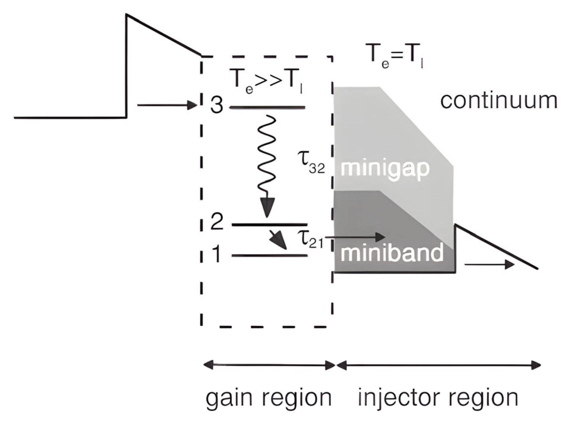
Figure 1. Basic design features of a generic QCL cell.
Coatings 15 00950 g001
Figure 2. Schematic of the DBR region.
Coatings 15 00950 g002
Figure 3. Schematic device representation of a GCSE-QCL DFB/DBR device with a central phase shift, Δφ [33].
Coatings 15 00950 g003
Figure 4. Structure of the SG-DBR laser [4].
Coatings 15 00950 g004
Figure 5. Schematic diagram of the dual-wavelength QCL. The front gain section, DBR1, the rear gain section, and DBR2 are electrically isolated by three grooves [24].
Coatings 15 00950 g005
Figure 6. Top view of the laser, with all sections described in the text: back DBR, main cavity, taper, front DBR, and antenna.
Coatings 15 00950 g006
Figure 7. Heaters are deposited directly on the silicon undercladding in proximity of the grating (a,b). A silicon etch step is performed to confine the heat laterally (c).
Coatings 15 00950 g007
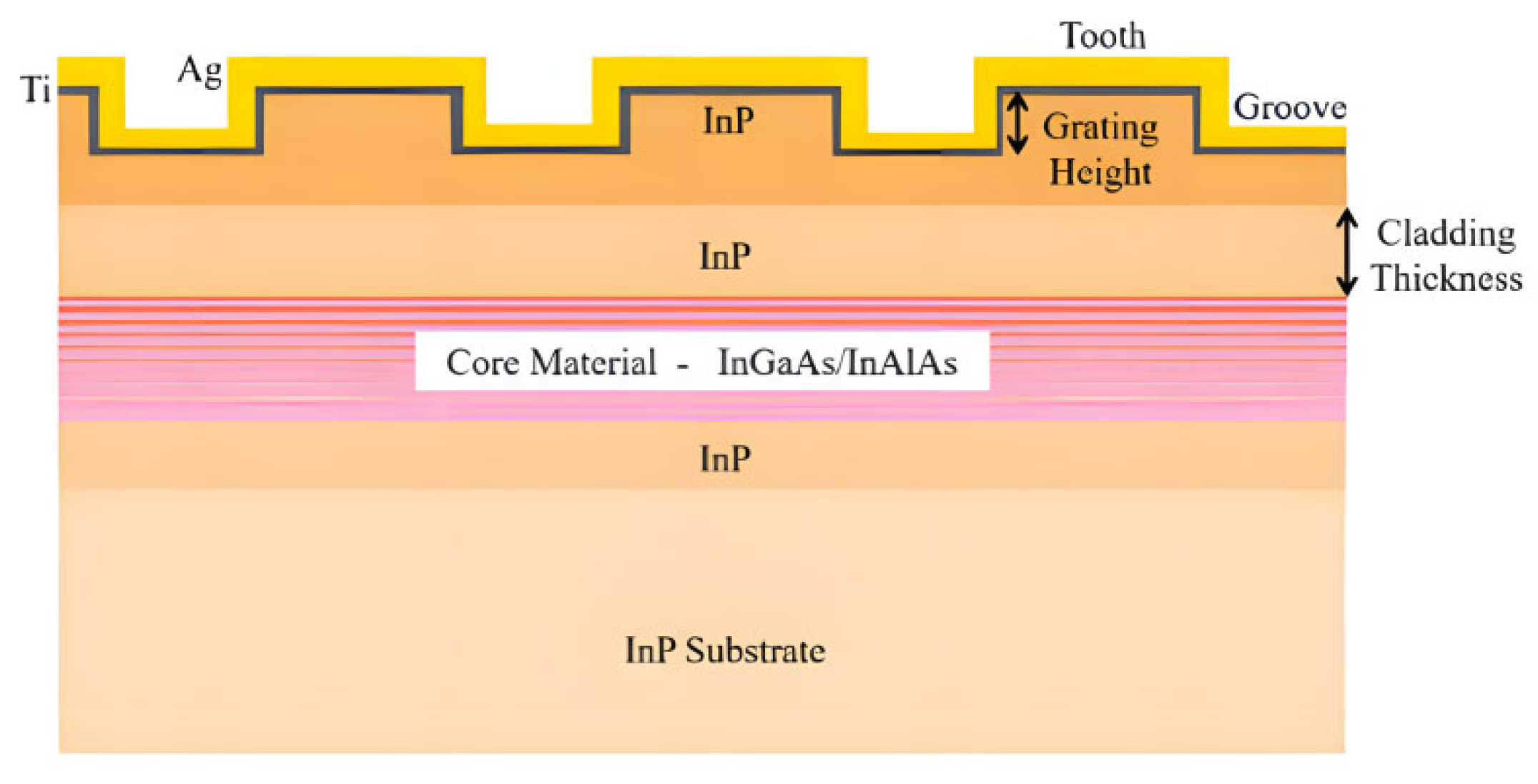
Figure 8. Schematic diagram of DBR-QCL. Cross-sectional structure along the cavity length, where Λ is the grating period.
Coatings 15 00950 g008
Figure 9. A side view of the device, adapted from [27].
Coatings 15 00950 g009
Figure 10. Schematic of a QCL with a first-order distributed Bragg reflector.
Coatings 15 00950 g010
Figure 11. The side view structural diagram of the device.
Coatings 15 00950 g011
Figure 12. Top view of the structure diagram of the device.
Coatings 15 00950 g012
Figure 13. Schematic image of the QC VCSEL [41].
Coatings 15 00950 g013
Figure 14. The schematic diagram of a typical THz-ADBR-QCL device.
Coatings 15 00950 g014
Figure 15. Schematic of SGDFB device structure, adapted from [7].
Coatings 15 00950 g015
Figure 16. Schematic diagram of the tapered sampling grating DFB QCL with an asymmetric coupling coefficient.
Coatings 15 00950 g016
Figure 17. Schematic diagram of the graded sampled grating DFB QCL.
Coatings 15 00950 g017
Figure 18. Schematic diagram of the metal cavity of terahertz QCLs.
Coatings 15 00950 g018
Figure 19. Schematic diagram of an integrated device, where Λ is 21.8 μm.
Coatings 15 00950 g019
Figure 20. Schematic of THz QCL with broken-period gratings.
Coatings 15 00950 g020
Figure 21. Schematic diagram of device cross-section.
Coatings 15 00950 g021
Figure 22. Laser ridge diagram [28].
Coatings 15 00950 g022
Figure 23. Schematic diagram of THz QCLs with DFB gratings, where Λ denotes the grating period.
Coatings 15 00950 g023
Figure 24. Device concept schematic of a neighbor DFB QCL.
Coatings 15 00950 g024
Figure 25. Conceptual design diagram of a dual-wavelength DFB-QCL.
Coatings 15 00950 g025
Figure 26. (a) The DFB-QCL array is shown with the epitaxial side down and bonded on a patterned AlN submount. (b) A sample grating DFB ridge. Z is the sampled period [57].
Coatings 15 00950 g026
Figure 27. Combining beams of arrays of single-mode THz QCLs with a custom-made lens and a blazed grating.
Coatings 15 00950 g027
Figure 28. THz-MOPA-QCL schematic diagram, which contains a first-order DFB laser, a tapered waveguide, and a wave coupler.
Coatings 15 00950 g028
Figure 29. DFB array device structure diagram.
Coatings 15 00950 g029
Figure 30. Side view of edge-emitting QCL [35].
Coatings 15 00950 g030
Table 1. Basic performance parameters.
ParameterMid-IR DFBMid-IR DBRTHz DFBTHz DBRRefs.
Wavelength3.36–10.56 μm3.5–8.4 μm2.58–4.7 THz2.7–5.1 THz[14,15,16,17,18]
Power2.4 W (CW)>1 W(CW)185 mW (p)30 μW (p)[3,12,13,16]
Consumption0.25 W (CW)≈5 W(sys)High≈2 W(pk)[19,20,21]
SMSR>30 dB>25 dB23 dB>25 dB[16,17,18,22]
Tuning230 cm−1±0.5 nm
95 cm−1
<1 cm−1±2 GHz[7,12,17,19]
Temperature408 K (CW)375 K (CW)473 K (p)170 K[10,13,16,21]
Table 2. Distinctive features of DFB-QCL vs. DBR-QCL.
FeatureDFB-QCLDBR-QCL
Mode Control κ L > 1 (SMSR > 30 dB) [16,22] u F S R > 1 2 u D B R [11]
Tuning RangeSG:230 cm−1 [7]
Dual-grating: <100 ns switch [23]
SG-DBR: 156 cm−1 [9]
Dual-DBR: Δλ = 0.8 μm [24]
Thermal/BeamSM-PEPC: 185 mW @THz [13,25]
Ring cavity: <3° div [26]
Ge-on-SOI: 0.009 nm/°C drift [19]
Asymmetric gratings: 14.6° × 12.3° [27]
FabricationDeep UV: 200 mm wafer [28]
ML design: −90% time [29,30,31]
IBE: Ra = 8.7 nm [32]
Hybrid: 91.4% yield [33]
Beam ControlRing gratings compress divergence to <3° [26,34]Asymmetric gratings achieve 14.6° × 12.3°
divergence [27]
Key
Applications
Gas sensing: <10 kHz linewidth [5]
FSO: 1.2 GHz BW [35]
Multi-gas: ppb-level CH4/N2O [4]
Dual-λ: <15 μs switch [24]
Abbreviations: κ—grating coupling coeff.; L—cavity length; △uFSR —free spectral range; △uDBR—DBR bandwidth; SG—sampled grating; SM-PEPC—surface-metal-phase photonic crystal; IBE—ion beam etching; Ra—sidewall roughness; ML—machine learning; FSO—free-space optical; BW—bandwidth.
Table 3. Single-mode QCL core performance limit.
MetricState-of-the-ArtKey TechnologyReference
Output Power14.5 W (pulsed)Cascade active region design[17]
Tuning Range880 GHzDigitally concatenated gratings[37]
Max. Temperature473 K (200 °C)Strain-compensated
InGaAs/InAlAs
[38]
Spectral Linewidth78 kHzExternal cavity feedback[5]
Manufacturing Cost$0.2/mW200 mm CMOS-compatible
process
[28]
Table 4. DBR-QCL research progress summary.
Ref.YearCore InnovationTest Cond.λPoutSMSRJth (kA/cm2)T0 (K)Key Perf.
[32]2020Low-loss IBEPulse@80 K, 1.8 kA/cm285.7 THz128 mW26.3 dB1.7592Scatt. loss↓34%
[40]2016Thin WG
low-pwr
CW@25 °C, 750 mA5.6 μm83.5 mW32.8 dB1.55176Pwr < 0.87 W
[33]2021DFB-DBR hybridPulse@25 °C, 2.8 A4.6 μm2.35 W33.5 dB1.85141Yield ↑40%
[40]2016Si-bonded thermalCW@25–100 °C, 850 mA7.4 μm62 mW34.2 dB1.70152Tune ± 0.3 cm−1/°C
[9]2012SG-DBR wideCW@25 °C, 850 mA4.62–4.91 μm57.6 mW>36 dB1.80145Tune > 150 cm−1
[4]2015SG-DBR
multi-gas
CW@25 °C, 800 mA7.64–8.62 μm61.2 mW>35 dB1.75150ppb CH4/N2O/H2O
[24]2021Dual-DBR switchPulse@25 °C, 1.8 A8.3/9.1 μm85/78 mW>31 dB1.75149Δλ = 0.8 μm, <15 μs
[12]2023Post-proc λ corrPulse@−10 °C, 1.5 kA/cm263.8 THz15.2 mW28.4 dB1.65105Precision 0.11 cm−1
[19]2019Ge-on-SOICW@25–85 °C, 1.1 A4.8 μm105 mW33.6 dB1.60158Drift 0.009 nm/°C
[16]2024102 °C SMCW@102 °C, 1.25 A8.4 μm1.18 W35.8 dB1.95182Drift 0.0078 nm/°C
[27]2020Non-rect gratingPulse@25 °C, 2.5 A4.6 μm2.17 W31.7 dB1.90132Div. < 15°
[42]2021Detune couplerCW@25 °C, 980 mA8.3 μm81.7 mW38.3 dB1.70167M2 < 1.48
[11]20233.6 mm gainPulse@80 K, 115 A/cm2111 THz8.7 mW26.1 dB0.11268Linewidth 4.18 MHz
[41]2022DBR-VCSELPulse@25 °C, 1.82 kA/cm24.3 μm12.3 mW28.5 dB1.79118Div. 8.4°
[43]2022THz
pwr-decouple
Pulse@80 K, 1.1 kA/cm285.7 THz11.3 mW29.3 dB1.0575Efficiency 32.4%
Table 5. DFB-QCL research progress summary.
Ref.YearInnovationTest Cond.λPoutSMSRJth
(kA/cm2)
T0(K)Key Perf.
[44]2019Non-rect grating optPulsed@300 K, 0.8–1.2 A~4.6 μm850 mW>30 dB1.05185Δλ/ΔT = 0.03 nm/K
[37]2020Taper SG + WGPulsed@288 K, 100 kHz~4.55 μm1.2 W>35 dB1.10210Div = 4.7°, M2 = 1.8
[48]2019SG THz mode ctrlPulsed@10 K3.2 THz18 mW>25 dB0.14-Δν/ΔT = 0.02 cm−1/K
[45]2022Graded SG compCW@50 K5.1 THz3.2 mW>30 dB0.15-Stable@10–100 K
[7]2012Dual-sect elec tuneCW@300 K4.6 μm>50 mW>30 dB0.93182Tune: 5.5 cm−1
[51]2025Broken-per grat effPulsed@78 K3.1 THz45 mW>28 dB0.22-Rad Eff ↑50%
[50]2024MMI beam shapeCW@80 K3.6 THz8.5 mW26 dB0.25-M2 = 1.6
[49]2018Hybrid-order BraggPulsed@80 K3.8 THz52 mW27 dB0.23-Surf Eff↑35%
[58]20222D metal grat steerPulsed@78 K,1μs3.5 THz120 mW28 dB0.18-Scan ± 30°
[26]2023Ring cavity SEPulsed@300 K~3.8 μm65 mW>30 dB0.75-Div < 3°
[46]2023Grat anti-hopCW@300 K, 1.5 Ith~4.8 μm210 mW25 dB0.95188ΔP < 5%
[52]2018AR coat high-TCW@90 °C4.6 μm170 mW26 dB0.65198SMSR@90 °C
[39]2022Strain-comp ARCW@20–90 °C6.12 μm170 mW26 dB0.98210ΔT = 70 °C
[5]2022Subλ HC gratingCW@298 K~5.4 μm108 mW32 dB0.85195Δν = 10 kHz
[28]2020200 mm CMOSCW@300 K4.6 μm150 mW>25 dB1.15-Yield 85%
[29]2021ML resonance predPulsed@80 K3.5 THz25 mW>25 dB0.20-Design cycle ↓90%
[23]2023Mono dual-λCW@300 K4.65/4.82 μm25/22 mW>30 dB0.92-Switch < 100 ns
[56]2018Dual-sect DFB gasPulsed@300 K5.18/5.26 μm>15 mW × 2>28 dB0.87-Δλ stab
[55]2016Dual-grat Y-WGCW@298 K7.73/7.85 μm>12 mW × 2>30 dB0.82-XT < −35 dB
[57]2015SG arrayCW@288 K4.55 μm1.5 W (16 ch)>25 dB1.05-Δλ < 0.02 μm
[47]2024PL array λ/4 gratPulsed@78 K3.8 THz185 mW (8 ch)28 dB0.16-φ err < λ/10
[38]2021WBC arrayPulsed@78 K3.9–4.1 THz110 mW (4 ch)>25 dB0.19-Tune 0.2 THz
[35]2025FS comm gratingCW@300 K4.7 μm80 mW>25 dB0.89180BW 1.2 GHz
Disclaimer/Publisher’s Note: The statements, opinions and data contained in all publications are solely those of the individual author(s) and contributor(s) and not of MDPI and/or the editor(s). MDPI and/or the editor(s) disclaim responsibility for any injury to people or property resulting from any ideas, methods, instructions or products referred to in the content.