
Methods of Distributing the IF-WS2 Modifier for Its Introduction into the Structure of the Al2O3 Aluminum Oxide Coating

 , ,
, ,  , ,
, ,  , and
, and 
Abstract
1. Introduction
2. Materials and Methods
2.1. Sample Preparation
- The Al2O3-coated aluminum alloy samples were immersed in a container filled with ethanol containing IF-WS2 NPs at a concentration of 15 g/L. This container was then subjected to sonication using a VCX 130 sonicator (Sonics & Materials Inc., Newtown, CT, USA) operating at a frequency of 20 kHz, delivering 10 kJ of energy to the system. The sonication process lasted for 5 min. Following this, the samples were left undisturbed in the solution for approximately 24 h to allow for natural settling.
- Similar to Method A, the container was initially sonicated under the same conditions. However, in the second step, the container was additionally placed in an ultrasonic bath for 15 min. After this secondary sonication, the samples were removed from the solution.
2.2. Microscopic Analysis
2.3. Structural Analysis
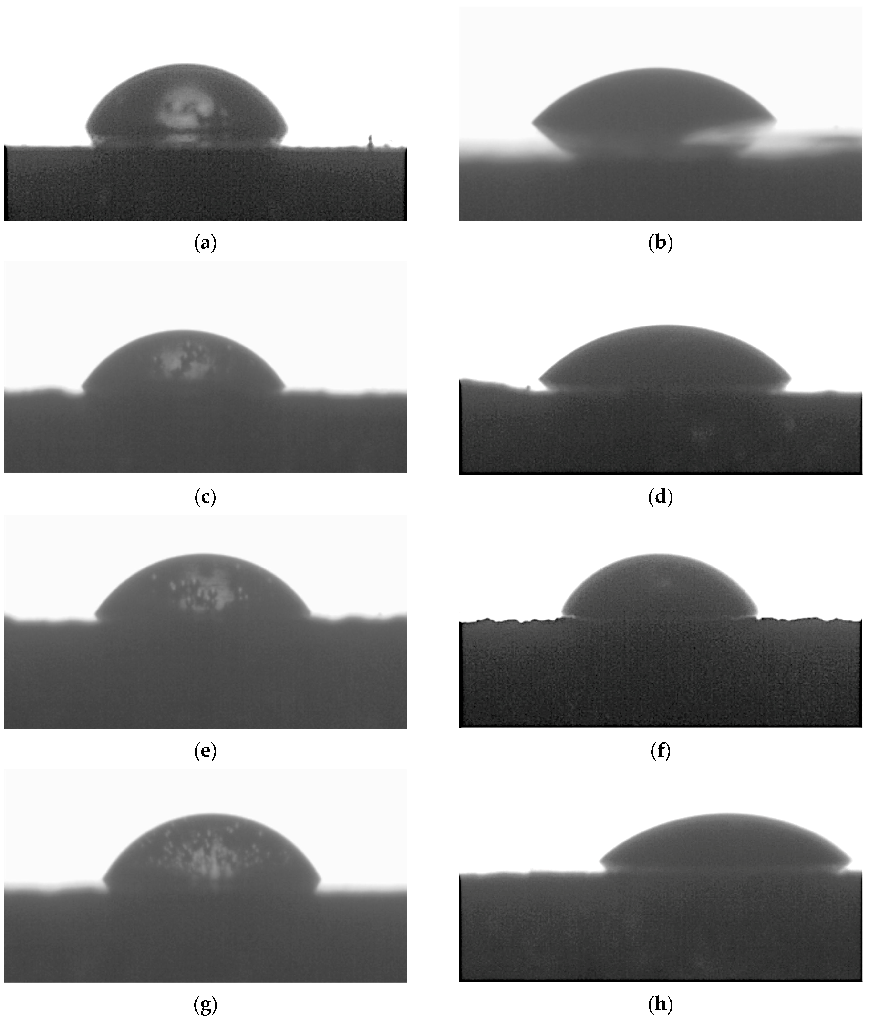
2.4. Surface Wettability Methodology
2.5. Experimental Design
3. Results and Discussion
4. Conclusions
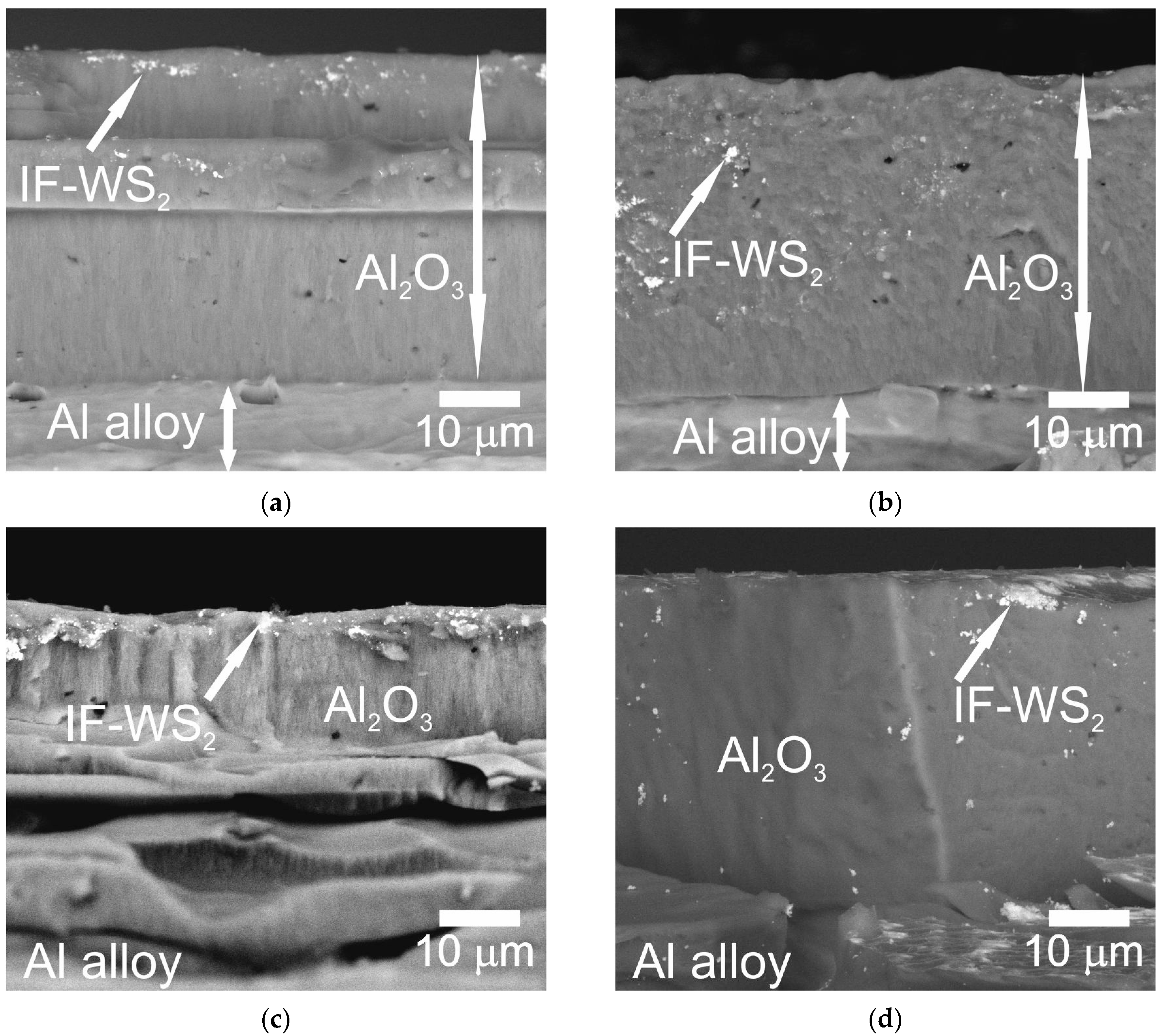
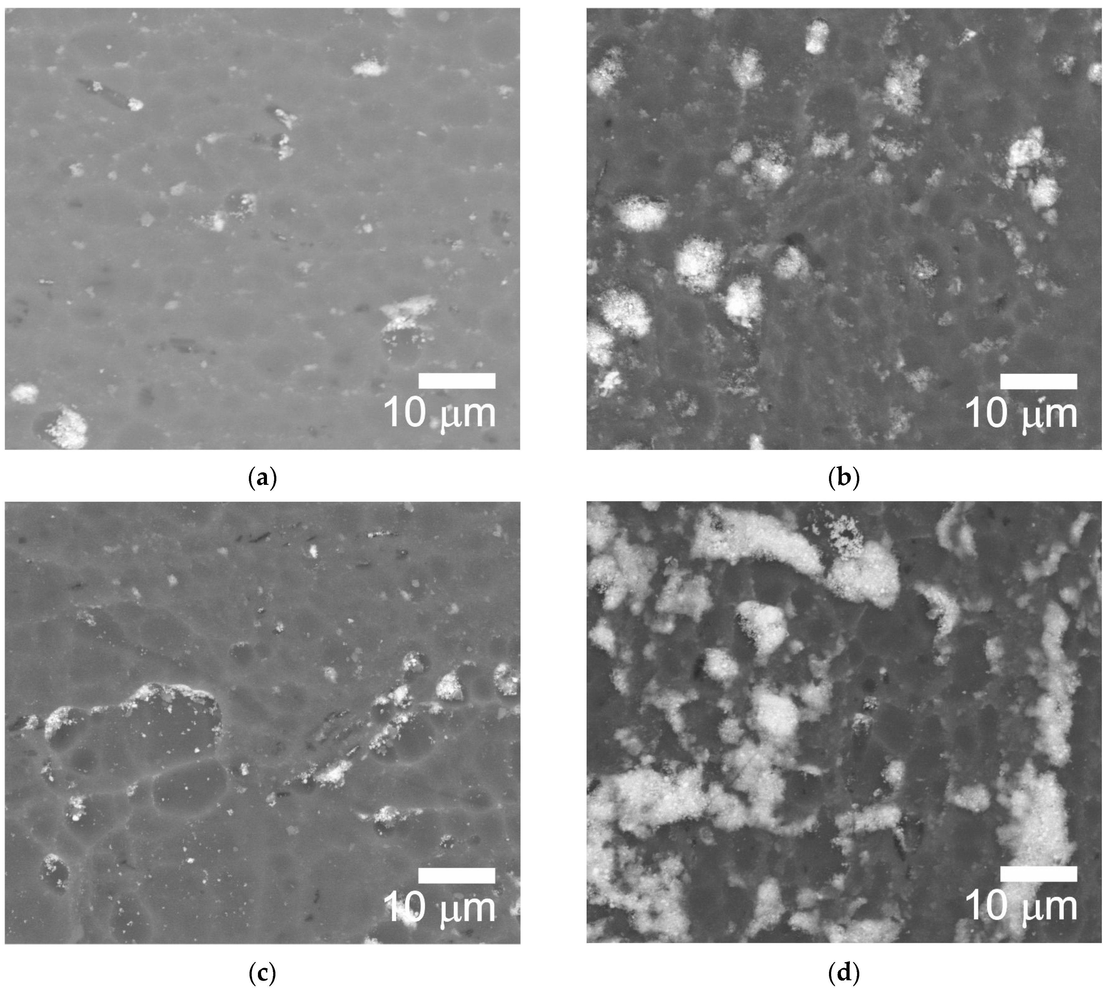
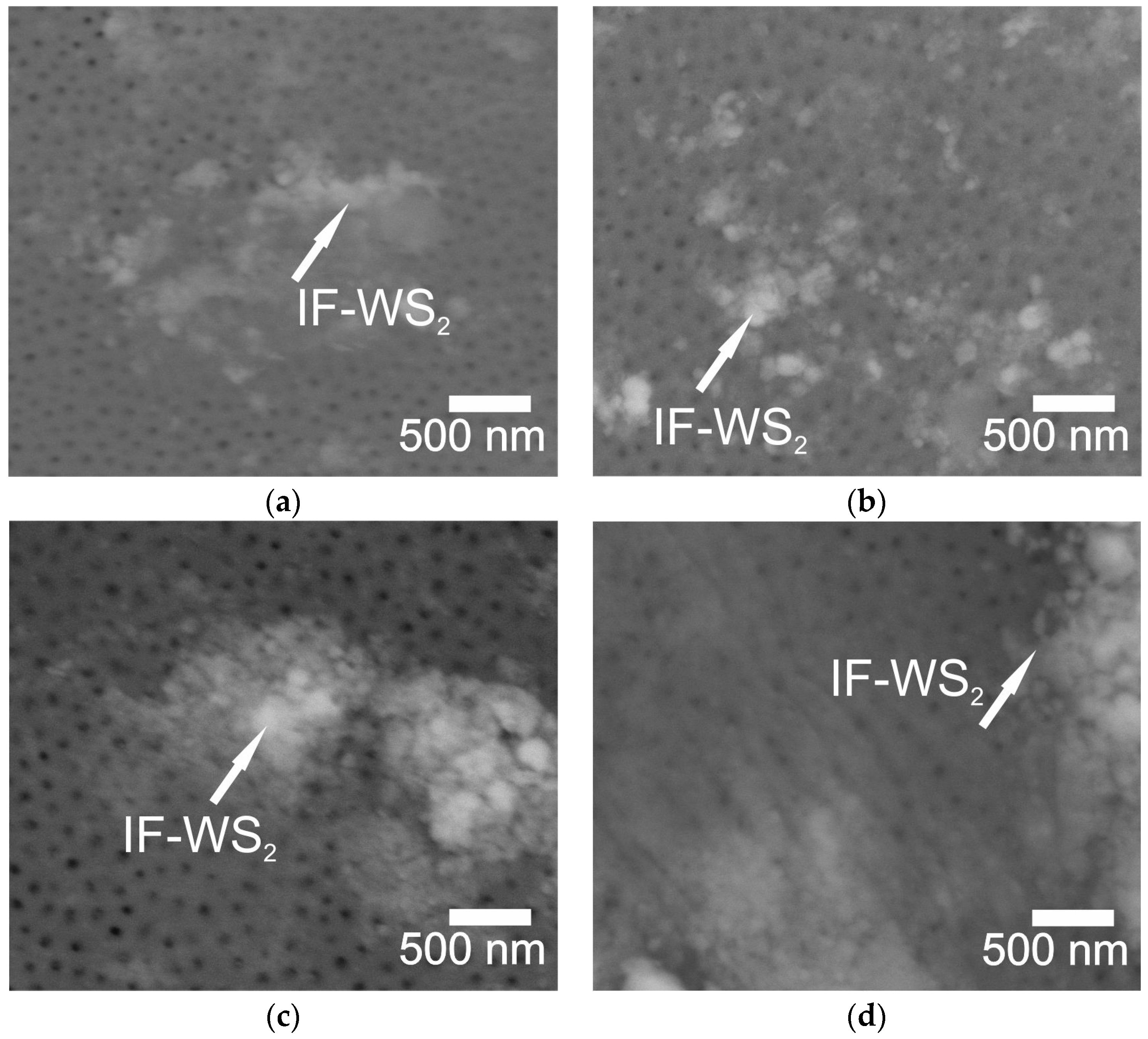
- Method A involved two stages: NP fragmentation in the sonicator and allowing samples for slow NPs deposition. Method A contributed to a more homogeneous distribution of NPs within the microstructure of Al2O3 coatings.
- GIXD analyses revealed the presence of a polycrystalline aluminum structure, rhombohedral phase of WS2, and tetragonal phase of WO3 originating from the IF-WS2 modifier.
- The formation of WO3 from WS2 is likely associated with high energy during WS2 dispersion in the sonicator.
- EDS analysis confirmed the presence of IF-WS2 in the microstructure of Al2O3.
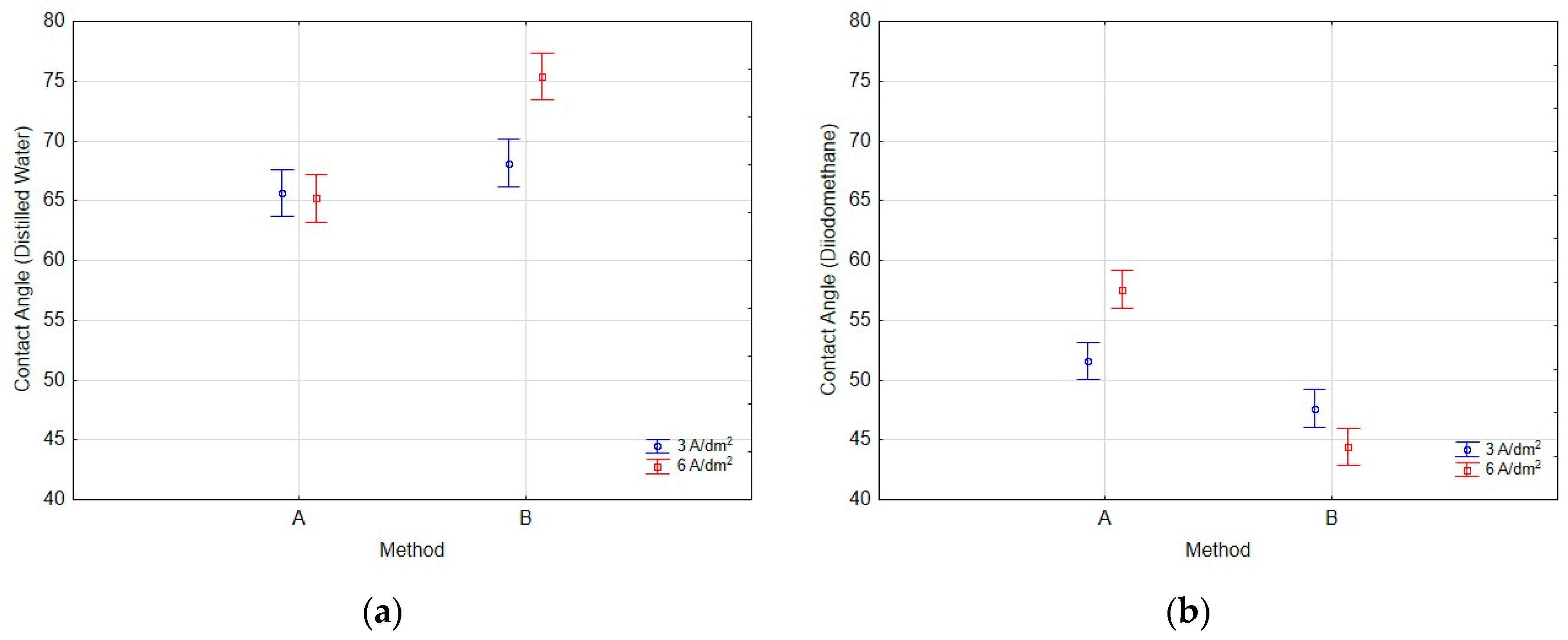
- Contact angle measurements using a non-polar liquid (diiodomethane) showed significantly lower values, which were primarily due to the liquid’s properties, namely its much lower surface tension compared to water and substantially lower polarity.
- Modification of coatings using Method A resulted in surfaces with lower contact angles measured with polar liquids and higher surface free energy compared to Method B, suggesting that Method A is more effective in enhancing the hydrophilicity and surface energy of coatings. This effect may stem from the even distribution of IF-WS2 nanoparticles in the near-surface oxide coating. In the case of Method B, the formation of agglomerates on the oxide coating surface significantly altered surface wettability.
- Surface free energy was higher for samples anodized for 60 min at a current density of 3 A/dm2, indicating that longer anodizing times combined with lower current density favor the creation of surfaces with higher surface energy.
- Statistical analysis demonstrated a linear relationship between the method of introducing IF-WS2 nanoparticles into Al2O3 coatings and the interaction between the method and current density on the values of contact angles measured with distilled water and diiodomethane. Additionally, it showed a linear relationship between the current density applied to obtain Al2O3 and the contact angle values measured with distilled water.
Author Contributions
Funding
Institutional Review Board Statement
Informed Consent Statement
Data Availability Statement
Acknowledgments
Conflicts of Interest
References
- Kwolek, P. Corrosion Behaviour of 7075 Aluminium Alloy in Acidic Solution. RSC Adv. 2020, 10, 26078–26089. [Google Scholar] [CrossRef] [PubMed]
- Martínez-Viademonte, M.P.; Abrahami, S.T.; Hack, T.; Burchardt, M.; Terryn, H. A Review on Anodizing of Aerospace Aluminum Alloys for Corrosion Protection. Coatings 2020, 10, 1106. [Google Scholar] [CrossRef]
- Runge, J.M. The Metallurgy of Anodizing Aluminum: Connecting Science to Practice; Springer: Cham, Switzerland, 2018; ISBN 9783319721774. [Google Scholar]
- European Aluminium. VISION 2050|A Vision for Strategic, Low Carbon and Competitive Aluminium; European Aluminium: Brussels, Belgium, 2022. [Google Scholar]
- Matijošius, T.; Padgurskas, J.; Bikulčius, G. Possibility of Phase Transformation of Al2O3 by a Laser: A Review. Crystals 2024, 14, 415. [Google Scholar] [CrossRef]
- Elkilany, H.A.; Shoeib, M.A.; Abdel-Salam, O.E. Influence of Hard Anodizing on the Mechanical and Corrosion Properties of Different Aluminum Alloys. Metallogr. Microstruct. Anal. 2019, 8, 861–870. [Google Scholar] [CrossRef]
- Kchaou, M. Friction Behavior of Anodic Oxide Layer Coating on 2017A T4 Aluminum Alloy under Severe Friction Solicitation: The Effect of Anodizing Parameters. Eng. Technol. Appl. Sci. Res. 2024, 14, 12574–12580. [Google Scholar] [CrossRef]
- Benea, L.; Simionescu-Bogatu, N.; Chiriac, R. Electrochemically Obtained Al2O3 Nanoporous Layers with Increased Anticorrosive Properties of Aluminum Alloy. J. Mater. Res. Technol. 2022, 17, 2636–2647. [Google Scholar] [CrossRef]
- Dervishi, E.; McBride, M.; Edwards, R.; Gutierrez, M.; Li, N.; Buntyn, R.; Hooks, D.E. Mechanical and Tribological Properties of Anodic Al Coatings as a Function of Anodizing Conditions. Surf. Coat. Technol. 2022, 444, 128652. [Google Scholar] [CrossRef]
- Kwolek, P.; Obłój, A.; Kościelniak, B.; Buszta, R.; Tokarski, T.; Krupa, K.; Gradzik, A.; Nowak, W.J.; Wojnicki, M.; Motyka, M. Wear Resistance of Hard Anodic Coatings Fabricated on 5005 and 6061 Aluminum Alloys. Arch. Civ. Mech. Eng. 2024, 24, 51. [Google Scholar] [CrossRef]
- Brudzisz, A.M.; Giziński, D.; Stępniowski, W.J. Incorporation of Ions into Nanostructured Anodic Oxides—Mechanism and Functionalities. Molecules 2021, 26, 6378. [Google Scholar] [CrossRef]
- Kmita, T.; Bara, M. Surface Oxide Layers with an Increased Carbon Content for Applications in Oil-Less Tribological Systems. Chem. Process Eng.-Inz. Chem. Proces. 2012, 33, 479–486. [Google Scholar] [CrossRef]
- Takaya, M.; Hashimoto, K.; Toda, Y.; Maejima, M. Novel Tribological Properties of Anodic Oxide Coating of Aluminum Impregnated with Iodine Compound. Surf. Coat. Technol. 2003, 169–170, 160–162. [Google Scholar] [CrossRef]
- Maejima, M.; Saruwatari, K.; Takaya, M. Friction Behaviour of Anodic Oxide Film on Aluminum Impregnated with Molybdenum Sulfide Compounds. Surf. Coat. Technol. 2000, 132, 105–110. [Google Scholar] [CrossRef]
- Posmyk, A. Kształtowanie Właściwości Tribologicznych Warstw Wierzchnich Na Bazie Aluminium; Wydawnictwo Politechniki Śląskiej: Gliwice, Poland, 2002. [Google Scholar]
- Li, B.; Wang, X.; Liu, W.; Xue, Q. Tribochemistry and Antiwear Mechanism of Organic-Inorganic Nanoparticles as Lubricant Additives. Tribol. Lett. 2006, 22, 79–84. [Google Scholar] [CrossRef]
- Wu, N.; Hu, N.; Wu, J.; Zhou, G. Tribology Properties of Synthesized Multiscale Lamellar WS2 and Their Synergistic Effect with Anti-Wear Agent ZDDP. Appl. Sci. 2020, 10, 115. [Google Scholar] [CrossRef]
- Gulzar, M.; Masjuki, H.H.; Kalam, M.A.; Varman, M.; Zulkifli, N.W.M.; Mufti, R.A.; Zahid, R. Tribological Performance of Nanoparticles as Lubricating Oil Additives. J. Nanoparticle Res. 2016, 18, 223. [Google Scholar] [CrossRef]
- Rapoport, L.; Bilik, Y.; Feldman, Y.; Homyonfer, M.; Cohen, S.R.; Tenne, R. Hollow Nanoparticles of WS2 as Potential Solid-State Lubricants. Nature 1997, 387, 791–793. [Google Scholar] [CrossRef]
- Rapoport, L.; Leshchinsky, V.; Lapsker, I.; Volovik, Y.; Nepomnyashchy, O.; Lvovsky, M.; Popovitz-Biro, R.; Feldman, Y.; Tenne, R. Tribological Properties of WS2 Nanoparticles under Mixed Lubrication. Wear 2003, 255, 785–793. [Google Scholar] [CrossRef]
- Song, J.; Hu, L.; Qin, B.; Fan, H.; Zhang, Y. Fabrication and Tribological Behavior of Al2O3/MoS2–BaSO4 Laminated Composites Doped with in Situ Formed BaMoO4. Tribol. Int. 2018, 118, 329–336. [Google Scholar] [CrossRef]
- Erdi Korkmaz, M.; Kumar Gupta, M. Nano Lubricants in Machining and Tribology Applications: A State of the Art Review on Challenges and Future Trend. J. Mol. Liq. 2024, 407, 125261. [Google Scholar] [CrossRef]
- Zak, A.; Feldman, Y.; Lyakhovitskaya, V.; Leitus, G.; Popovitz-Biro, R.; Wachtel, E.; Cohen, H.; Reich, S.; Tenne, R. Alkali Metal Intercalated Fullerene-like MS2 (M = W, Mo) Nanoparticles and Their Properties. J. Am. Chem. Soc. 2002, 124, 4747–4758. [Google Scholar] [CrossRef]
- Feldman, Y.; Zak, A.; Popovitz-Biro, R.; Tenne, R. New Reactor for Production of Tungsten Disulfide Hollow Onion-like (Inorganic Fullerene-like) Nanoparticles. Solid State Sci. 2000, 2, 663–672. [Google Scholar] [CrossRef]
- Sawyer, W.G.; Blanchet, T.A. Lubrication of Mo, W, and Their Alloys with H2S Gas Admixtures to Room Temperature Air. Wear 1999, 225–229, 581–586. [Google Scholar] [CrossRef]
- Voevodin, A.A.; Zabinski, J.S. Nanocomposite and Nanostructured Tribological Materials for Space Applications. Compos. Sci. Technol. 2005, 65, 741–748. [Google Scholar] [CrossRef]
- Sorrentino, A. Tribology of Self-Lubricating Polymer Nanocomposites. In Self-Lubricating Composites; Springer: Berlin/Heidelberg, Germany, 2018; pp. 105–131. [Google Scholar] [CrossRef]
- Li, D.-l.; Jing, X.; Chen, H.; Sun, K.; Chen, W.; Huang, H.-g.; Ren, W.-j. Effects of Graphene Content in Alkaline Silicate Electrolyte on AA1060 Pure Aluminum Micro-Arc Oxidation Coating. Int. J. Appl. Ceram. Technol. 2024, 21, 1789–1801. [Google Scholar] [CrossRef]
- Chen, L.; Liu, Z.; Shen, Q. Enhancing Tribological Performance by Anodizing Micro-Textured Surfaces with Nano-MoS2 Coatings Prepared on Aluminum-Silicon Alloys. Tribol. Int. 2018, 122, 84–95. [Google Scholar] [CrossRef]
- Han, X.; Thrush, S.J.; Zhang, Z.; Barber, G.C.; Qu, H. Tribological Characterization of ZnO Nanofluids as Fastener Lubricants. Wear 2021, 468–469, 203592. [Google Scholar] [CrossRef]
- Korzekwa, J.; Gądek-Moszczak, A.; Zubko, M. Influence of the Size of Nanoparticles on the Microstructure of Oxide Coatings. Mater. Sci. 2018, 53, 709–716. [Google Scholar] [CrossRef]
- Gorycza, T.; Dercz, G.; Prusik, K.; Pająk, L.; Łągiewska, E. Crystallite Size Determination of MgO Nanopowder from X-Ray Diffraction Patterns Registered in GIXD Technique. Solid State Phenom. 2010, 163, 177–182. [Google Scholar] [CrossRef]
- Kyrylenko, S.; Warchoł, F.; Oleshko, O.; Husak, Y.; Kazek-Kęsik, A.; Korniienko, V.; Deineka, V.; Sowa, M.; Maciej, A.; Michalska, J.; et al. Effects of the Sources of Calcium and Phosphorus on the Structural and Functional Properties of Ceramic Coatings on Titanium Dental Implants Produced by Plasma Electrolytic Oxidation. Mater. Sci. Eng. C 2021, 119, 111607. [Google Scholar] [CrossRef]
- Kazek-Kȩsik, A.; Kalemba-Rec, I.; Simka, W. Anodization of a Medical-Grade Ti-6Al-7Nb Alloy in a Ca(H2PO2)2-Hydroxyapatite Suspension. Materials 2019, 12, 3002. [Google Scholar] [CrossRef]
- Owens, D.K.; Wendt, R.C. Estimation of the Surface Free Energy of Polymers. Appl. Polym. Sci. 1969, 13, 1741–1747. [Google Scholar] [CrossRef]
- Wu, S. Calculation of Interfacial Tension in Polymer Systems. J. Polym. Sci. Polym. Symp. 1971, 34, 19–30. [Google Scholar] [CrossRef]
- Pietraszek, J.; Dwornicka, R.; Krawczyk, M.; Kołomycki, M. The Non-Parametric Approach to the Quantification of the Uncertainty in the Design of Experiments Modelling. In Proceedings of the UNCECOMP 2017—2nd International Conference on Uncertainty Quantification in Computational Sciences and Engineering, Rhodes Island, Greece, 15–17 June 2017; pp. 598–604. [Google Scholar] [CrossRef]
- Pietraszek, J.; Radek, N.; Goroshko, A.V.; Jana, A.; Ii, P. Challenges for the DOE Methodology Related to the Introduction of Industry 4.0. Prod. Eng. Arch. 2020, 26, 190–194. [Google Scholar] [CrossRef]
- Dudek, A.; Lisiecka, B.; Radek, N.; Orman, Ł.J.; Pietraszek, J. Laser Surface Alloying of Sintered Stainless Steel. Materials 2022, 15, 6061. [Google Scholar] [CrossRef] [PubMed]
- Shinde, P.A.; Jun, S.C. Review on Recent Progress in the Development of Tungsten Oxide Based Electrodes for Electrochemical Energy Storage. ChemSusChem 2020, 13, 11–38. [Google Scholar] [CrossRef]
- Mandal, D.; Routh, P.; Nandi, A.K. A New Facile Synthesis of Tungsten Oxide from Tungsten Disulfide: Structure Dependent Supercapacitor and Negative Differential Resistance Properties. Small 2018, 14, 1702881. [Google Scholar] [CrossRef]


| Sample Designation | The Electrolysis Conditions for Charge Density of 180 [A·min/dm2] | The Conditions of Introducing IF-WS2 NPs | |
|---|---|---|---|
| Time [min] | J [A/dm2] | ||
| 1 | 60 | 3 (−1) | Method A (−1) |
| 2 | 60 | 3 (−1) | Method B (1) |
| 3 | 30 | 6 (1) | Method A (−1) |
| 4 | 30 | 6 (1) | Method B (1) |
| Area | Element Line | Atom % | Atom % Error | Formula | Compnd % |
|---|---|---|---|---|---|
| 1 | O K | 45.44 | ±2.26 | O | 27.30 |
| Al K | 49.30 | ±0.50 | Al | 49.94 | |
| S K | 2.38 | ±0.16 | S | 2.87 | |
| W L | 2.88 | ±0.25 | W | 19.90 | |
| Total | 100.00 | 100.00 | |||
| 2 | O K | 48.80 | ±1.07 | O | 34.05 |
| Al K | 49.25 | ±0.28 | Al | 57.96 | |
| S K | 1.16 | ±0.10 | S | 1.63 | |
| W L | 0.79 | ±0.09 | W | 6.36 | |
| Total | 100.00 | 100.00 |
| Sample | Contact Angle (°) (Diiodomethane) | Standard Deviation (°) | Contact Angle (°) (Distilled Water) | Standard Deviation (°) | Surface Free Energy WORK [mN/m] | Surface Free Energy WU [mN/m] |
|---|---|---|---|---|---|---|
| 1 | 51.60 | 2.58 | 65.65 | 2.74 | 39.34 | 45.18 |
| 2 | 47.64 | 1.79 | 68.15 | 5.14 | 39.27 | 45.07 |
| 3 | 57.59 | 4.53 | 65.21 | 3.59 | 38.20 | 43.86 |
| 4 | 44.39 | 4.28 | 75.39 | 5.76 | 37.95 | 42.83 |
Disclaimer/Publisher’s Note: The statements, opinions and data contained in all publications are solely those of the individual author(s) and contributor(s) and not of MDPI and/or the editor(s). MDPI and/or the editor(s) disclaim responsibility for any injury to people or property resulting from any ideas, methods, instructions or products referred to in the content. |
© 2024 by the authors. Licensee MDPI, Basel, Switzerland. This article is an open access article distributed under the terms and conditions of the Creative Commons Attribution (CC BY) license (https://creativecommons.org/licenses/by/4.0/).
Share and Cite
Korzekwa, J.; Niedźwiedź, M.; Dercz, G.; Cwynar, K.; Sowa, M.; Bara, M.; Simka, W. Methods of Distributing the IF-WS2 Modifier for Its Introduction into the Structure of the Al2O3 Aluminum Oxide Coating. Coatings 2024, 14, 883. https://doi.org/10.3390/coatings14070883
Korzekwa J, Niedźwiedź M, Dercz G, Cwynar K, Sowa M, Bara M, Simka W. Methods of Distributing the IF-WS2 Modifier for Its Introduction into the Structure of the Al2O3 Aluminum Oxide Coating. Coatings. 2024; 14(7):883. https://doi.org/10.3390/coatings14070883
Chicago/Turabian StyleKorzekwa, Joanna, Mateusz Niedźwiedź, Grzegorz Dercz, Krzysztof Cwynar, Maciej Sowa, Marek Bara, and Wojciech Simka. 2024. "Methods of Distributing the IF-WS2 Modifier for Its Introduction into the Structure of the Al2O3 Aluminum Oxide Coating" Coatings 14, no. 7: 883. https://doi.org/10.3390/coatings14070883
APA StyleKorzekwa, J., Niedźwiedź, M., Dercz, G., Cwynar, K., Sowa, M., Bara, M., & Simka, W. (2024). Methods of Distributing the IF-WS2 Modifier for Its Introduction into the Structure of the Al2O3 Aluminum Oxide Coating. Coatings, 14(7), 883. https://doi.org/10.3390/coatings14070883