Article

Microstructure and Corrosion Resistance of Laser-Cladded FeCo1.5CrNi1.5Ti0.5 High-Entropy Alloy Coatings

1
State Key Laboratory for Performance and Structure Safety of Petroleum Tubular Goods and Equipment Materials, CNPC Tubular Goods Research Institute, Xi’an 710077, China
2
Research Institute of Engineering Technology, PetrChina Xinjiang Oilfield Company, Karamay 834000, China
3
Shaanxi Institute of Applied Physics and Chemistry, Xi’an 710061, China
4
Xi’an Beifang Qinghua Mechanical and Electrical Co., Ltd., Xi’an 710025, China
5
School of Materials Engineering, Xi’an Aeronautical University, Xi’an 710077, China
*
Authors to whom correspondence should be addressed.
Coatings 2024, 14(12), 1608; https://doi.org/10.3390/coatings14121608
Submission received: 3 July 2024 / Revised: 13 December 2024 / Accepted: 15 December 2024 / Published: 23 December 2024

Abstract

:
Due to their excellent mechanical properties and corrosion resistance, high-entropy alloys (HEAs) have the potential to be used as new engineering structures and functional materials. In this study, an FeCo1.5CrNi1.5Ti0.5HEA coating was prepared on the surface of a 1Cr18Ni9Ti alloy by laser cladding technology. Phase structure and microstructure were characterized by XRD and using an SEM. The corrosion resistance was evaluated by an electrochemical workstation, and the polarization curves were obtained in simulated seawater and 3.5 wt.% NaCl and 5% HCl solutions. The corrosion morphology of the Fe-based HEA coating was further characterized using the SEM, super depth of field observation, and 3D topological images. The results showed that the Fe-based HEA coating had a single-phase FCC structure with a grain size of about 10.7 ± 0.25 μM. Electrochemical analysis results showed that the corrosion resistance of the current Fe-based HEA coating was poor in HCl solutions. However, it exhibited good corrosion properties in simulated seawater and 3.5 wt.% NaCl solutions. Further analysis of the corrosion morphology revealed that in simulated seawater and the 3.5 wt.% NaCl solution, the surface of the current Fe-based HEA coating exhibited a preferential corrosion tendency between dendrites, while in the 5% HCl solution, it exhibited more obvious pitting characteristics. The results indicate that the current Fe-based HEA coating exhibits good comprehensive performance, especially in an acidic Cl corrosion environment. These findings provide a reference for the application of laser cladding prepared Fe HEA coatings.

1. Introduction

High-entropy alloys (HEAs) are composed of five or more principal elements in equiatomic or near-equiatomic proportions [1,2]. The structures of HEAs include face-centered cubic (FCC), body-centered cubic (BCC), hexagonal close-packed (HCP), and amorphous structures [3,4]. The mixing entropy of HEAs exceeds 1.5R (where R is the gas constant), which inhibits the formation of intermetallic compounds and results in simple solid solution structures [5]. Compared with traditional alloys characterized by a single predominant element, HEAs are considered a new type of versatile metallic material, due to their high mixing entropy and significant lattice distortion, which contribute to their high strength, high fracture toughness, excellent wear resistance, corrosion resistance, and high-temperature stability [6,7,8]. However, increased costs can be incurred when using high-entropy alloys as the primary material for engineering structural components.
Laser cladding technology employs a laser beam as its heat source to melt and fuse the cladding material onto the surface of a substrate. This results in an efficient surface modification technique that produces a uniform and dense cladding layer with a thickness on the order of millimeters [9].This technology is an advanced material processing and shaping technique that combines rapid solidification and prototyping with laser technology, characterized by a low dilution rate, high cooling speed, good metallurgical bonding with the metal substrate, and ease of automation [10]. Currently, the corrosion resistance of HEA coatings prepared by laser cladding technology has garnered widespread attention in the field of corrosion research [11,12,13,14]. For instance, Guo et al. [11] studied the microstructure and corrosion behaviors of a laser cladding-produced FeCoCrNiAl0.5Ti0.5 HEA coating on an AISI 1045 steel substrate. The results revealed that the HEA coating in a 3.5 wt.% NaCl solution exhibited pretty good corrosion resistance due to the uniform microstructure and addition of corrosion-resistant elements (such as Cr). A dense passive film mainly constituted of Cr2O3 could significantly inhibit the corrosion process. The corrosion rate of the HEA coating is 32.8% compared to that of the substrate. Zhao et al. [15] employed a coaxial laser powder feeding method to fabricate CoCrFeNiMn high-entropy alloy coatings on the surface of a commercial 304 stainless steel substrate. Their study indicated that reducing the laser power could prevent void formation and the coarsening of grains in the cladding layer. Additionally, this CoCrFeNiMn coating in a 3.5 wt% NaCl solution exhibited a higher corrosion potential, Ecorr (−124.6 ± 5.3 mV),and a lower corrosion current density, Icorr (20.2 ± 2.6 μA·cm−2), and showed excellent corrosion resistance compared to the metal substrate surface.
The as-cast FeCo1.5CrNi1.5Ti0.5 high-entropy alloy exhibits excellent mechanical properties and corrosion resistance [16,17]. In this system, Co, Cr, Ni, and Ti are fundamental elements that enhance the corrosion resistance of the alloy system. Additionally, due to the “cocktail effect” of HEAs, the synergistic effect between different elements could further enhance the corrosion resistance [18,19]. Compared to the FeCoCrNiAl0.5Ti0.5 and CoCrFeNiMn HEAs, the FeCo1.5CrNi1.5Ti0.5 HEA has a higher content of Ni and Ti. The electrochemical properties of the bulk FeCo1.5CrNi1.5Ti0.5 HEA prepared by the induction melting method have been investigated in three solutions of H2SO4, NaOH, and NaCl at ambient temperature [16]. It revealed that this FeCo1.5CrNi1.5Ti0.5 alloy exhibited good corrosion resistance compared to Mo-free alloy. Additionally, this alloy is susceptible to pitting corrosion in a NaCl solution. However, few research efforts have been made to investigate the FeCo1.5CrNi1.5Ti0.5 HEA coating fabricated by laser cladding, especially its corrosion resistance in different corrosive environments, which still needs to be further investigated.
In this study, an FeCo1.5CrNi1.5Ti0.5HEA coating was fabricated on a 1Cr18Ni9Ti stainless steel substrate using laser cladding technology. The phase structure and microstructure were characterized by XRD, an SEM, and 3D super-depth microscope. The corrosion resistance was evaluated by an electrochemical workstation and the corrosion resistance of the coating in various corrosive environments was systematically evaluated. This research could provide a reference for the engineering application of HEA coatings.

2. Materials and Methods

In this study, 1Cr18Ni9Ti austenitic stainless steel was employed as the metal substrate with dimensions of 80 mm × 80 mm × 30 mm. Analysis of its chemical composition (wt.%) was carried out by a Handheld X-ray Fluorescence (XRF, Hitachi High-Tech Co., Ltd., Ibaraki, Japan) spectrometer, and the result is as follows: C, 0.11; Si, 0.95; Mn, 1.3; Cr, 17.5; Ni, 8.5; Ti, 0.4; Fe, the balance. The materials used for the preparation of the laser cladding coatings were high-purity elements of Fe, Co, Cr, Ni, and Ti. The composition design of HEA was FeCo1.5CrNi1.5Ti0.5. Initially, each high-purity element was manually polished to remove surface oxides and precisely weighed according to the composition design. The HEA ingot was subsequently fabricated using a vacuum melting furnace. The ingots were melted four times to ensure the homogeneity of the microstructure and chemical composition. Subsequently, HEA powder was obtained through gas atomization, and particles within the size range of 50-180 μM were selected for laser cladding. Finally, Fe-Co-Cr-Ni-Ti HEA coating samples were prepared on the base material surface using laser cladding technology. To prevent oxidation, Ar gas (99.96%) was used as a protective atmosphere during the cladding process, with a flow rate of 15 L∙min−1. The selected laser cladding experimental parameters were as follows: P = 3.0 KW, scanning speed v = 3.0 m/min, spot diameter 4 mm, and an overlap rate of 45%. A single layer was approximately 1 mm thick, and the cladding had a thickness of around 10 mm. The rectangular samples were cut by wire cutting. To remove the machining marks, those samples were polished with SiC paper. The final polish was conducted with a 0.5 μM diamond paste. The test sample size is 5 × 5 × 10 mm.
The crystal structure was analyzed by X-ray diffraction (XRD, Malvern Panalytical Co., Ltd., Almelo, Netherlands) using an X’Pert Pro diffractometer with Cu-Kα radiation (λ = 0.15406 nm). The scanning angle range of 2θ is from 20° to 80° with a step size of 0.02°.The lateral surface of the coating was observed by an optical microscope (OM) after etching with an FeCl3 and HCl solution. The microstructural morphology was characterized by a JSM-6510A scanning electron microscope (SEM, JEOL Co., Ltd., Akishima, Japan) with energy-dispersive spectroscopy (EDS, Oxford Instruments Co., Ltd., Abingdon, UK) using an acceleration voltage of 40 keV. The corrosion surface was also observed by an SEM.
The corrosion resistance of the coating was evaluated by a Zahner ZenniumPro electrochemical workstation. The three-electrode system consisted of a saturated calomel reference electrode, a platinum counter electrode, and the sample under test as the working electrode. To ensure the stability of the test, the samples were immersed in the corrosive solution for 30 min before the corrosion resistance testing. The open circuit potential (OCP) of the sample was measured in the various corrosive solutions for 3600 s to ensure that the ECOP value reached a steady state. The dynamic potential scanning range was −2.5 V to +2.5 V with a scanning rate of 5 mV/s. The initial potential was lower than the corresponding EOCP of the tested sample. EIS measurements were performed with an amplitude of ±10 mV (vs. OCP) and a range of frequency from 100 kHz to 0.01 Hz. The corrosive environments selected included a 3.5% mass NaCl solution, 5% HCl, and simulated seawater. The chemical composition of simulated seawater is shown in Table 1. Following the electrochemical tests, the samples were examined for their ultra-depth morphology using the RH-2000 3D super-depth microscope (Hirox-japan Co., Ltd., Fukuoka, Japan).

3. Results and Discussions

3.1. XRD Analysis

The crystal structure of the present alloy was characterized by XRD. Figure 1a shows the macroscopic sample prepared by laser cladding and the inset exhibits the OM of the lateral surface of the coating. No significant cracks were detected on the surface of the sample. However, a few minor voids were observed. The thickness of the coating after polishing is about 4.5 mm. Figure 1b exhibits the XRD patterns of HEA powder prepared by atomization and HEA alloy coating obtained by laser cladding. It can be seen that the HEA powder has formed a single-phase solid solution with a single FCC phase structure. It indicates that the high-entropy alloy powder prepared by atomization has a good chemical composition and structural homogeneity. The HEA powder demonstrates preferential growth characteristics on the {111} crystal plane. Those characteristics are attributed to the uniform cooling rate in three dimensions during the atomization process, leading to preferential growth on the {111} crystal plane. Additionally, the rapid cooling rate suppresses the formation of secondary phases, resulting in a single-phase crystal structure. It should be noted that the cooling rate of the gas atomization method is approximately 104 ~ 105 K/s [20]. Furthermore, the HEA coating also displays an FCC phase structure, and no secondary phase precipitation is observed. This indicates that the HEA coating produced by laser cladding could effectively maintain the single-phase structure of the powder. In contrast to the preferred orientation of grain growth in HEA powder, the grains of the HEA coating exhibit preferential growth on the {200} crystal plane. This difference might be due to the complex temperature and stress gradients induced by the laser cladding technique, leading to a change in the preferred orientation of grain growth. The XRD analysis results are consistent with the XRD analysis results of alloys with the same composition in the as-cast condition [21].

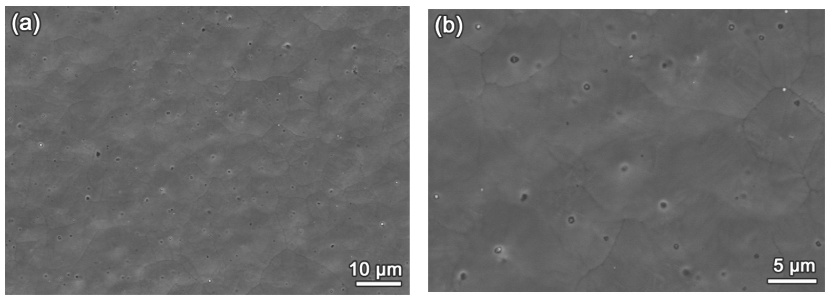
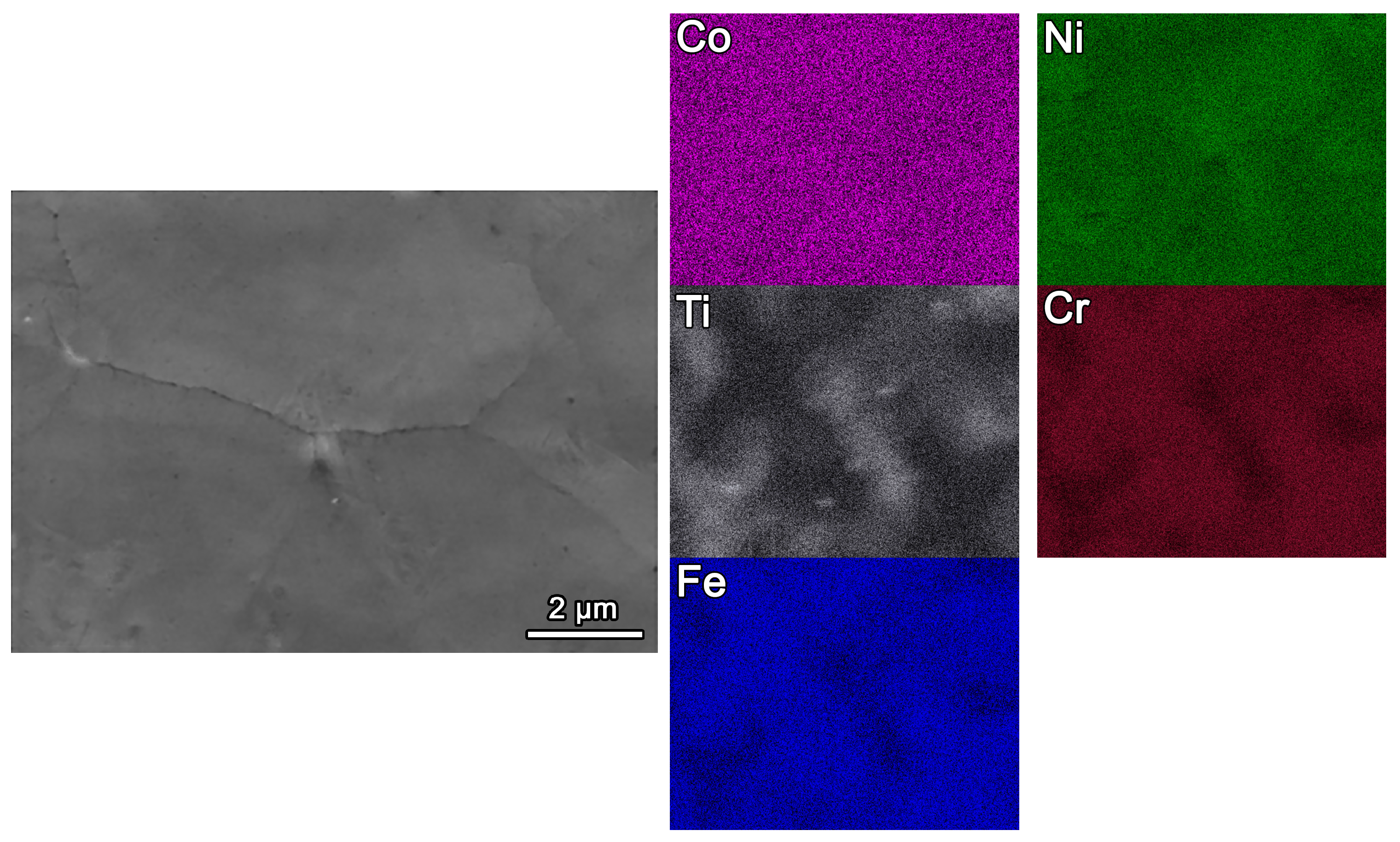
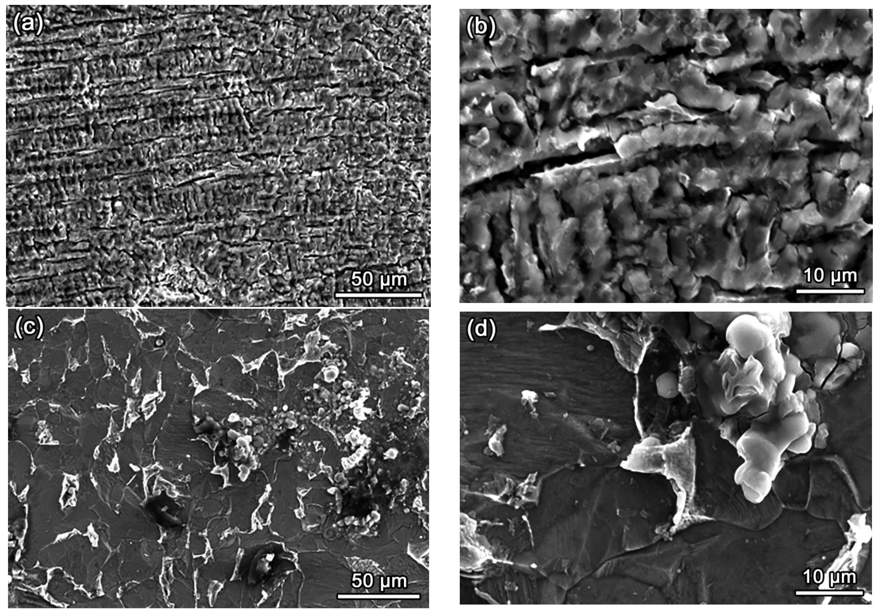
3.2. Microstructures of Fe-Based HEA Coatings

Figure 2 shows the microstructure of the HEA coating at different magnifications. It reveals that the HEA coating displays a typical equiaxed grain structure with average grain sizes of approximately 10.7 ± 0.25 μM and no significant porosity at the grain boundaries. Generally, this equiaxed grain morphology is associated with the high energy density and rapid cooling rate of the laser cladding process. Combined with the XRD analysis results, it indicates that the current HEA coating possesses a single-phase structure, characterized by fine grain boundaries and high density. The fine grain characteristics are attributed to the complex thermal cycling history [22,23]. Therefore, the HEA coating was successfully prepared by laser cladding technology, characterized by its uniform distribution, fine grain structure, and no porosity.
The morphology and the corresponding EDS analysis results to determine the elemental characteristics of the HEA coating are presented in Figure 3. No significant contrast was observed according to the brightness levels. Based on the EDS results, it can be seen that this coating surface was composed of Fe, Co, Ni, Cr, and Ti elements, and those chemical elements exhibited an inhomogeneous distribution. Specifically, the Fe, Co, and Ni elements exhibited a homogeneous distribution, whereas the Cr and Ti elements showed an inhomogeneous distribution. Dendritic morphological characteristics were observed in the distribution maps of Cr and Ti elements. Taking into account previous research work [16], it is known that the dendrite is Cr-rich and the interdendrite is Ti-rich. The segregation of Cr and Ti elements was attributed to their high segregation energy [24]. Meanwhile, due to their similar electronegativity and atomic radius, Ni, Fe, and Co elements exhibited a uniform distribution.

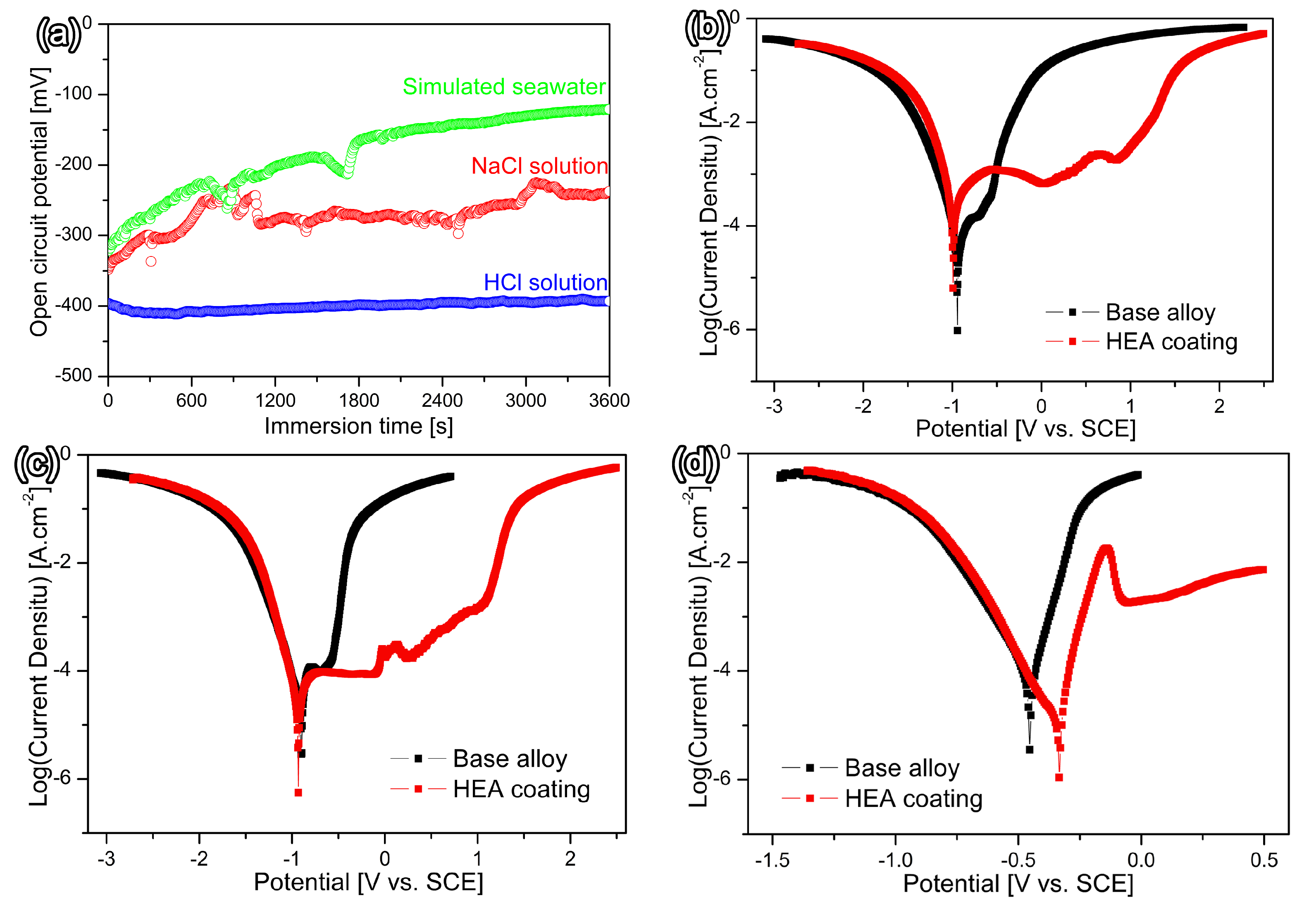
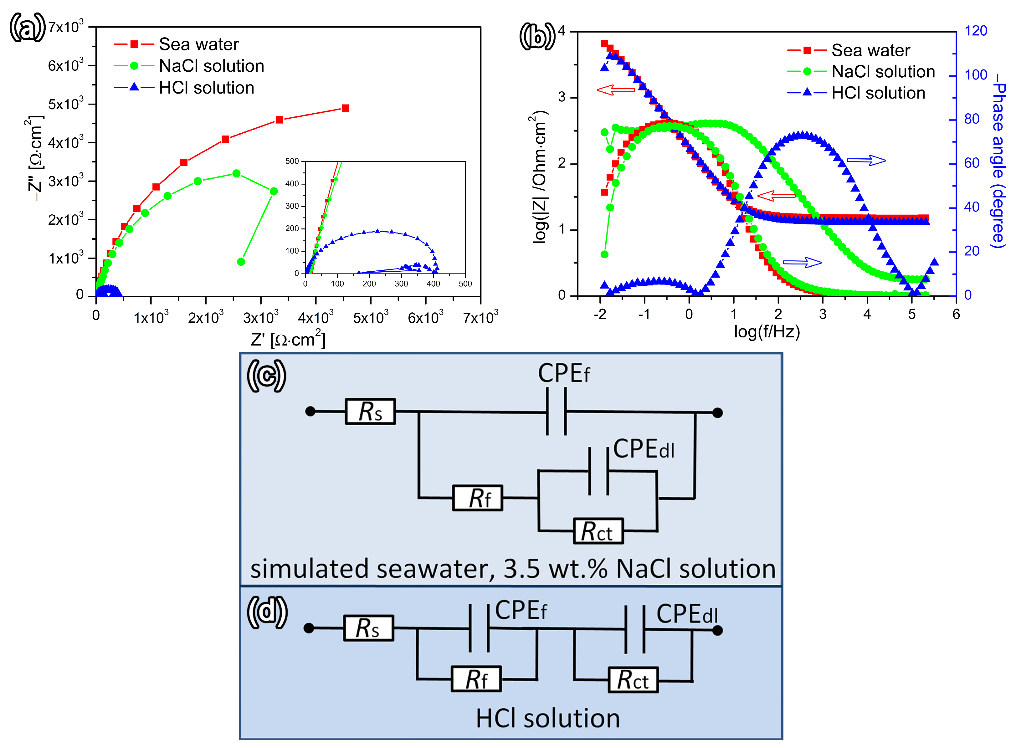
3.3. Corrosion Resistance

Figure 4 presents the OCP and dynamic polarization curves of Fe-based HEA coatings and the metal substrate in various corrosive environments at room temperature. According to Figure 4a, the open circuit potential, EOCP, of the present HEA coating exhibits obvious differences in various corrosive environments. The OCP curve of the present coating remains in a relatively stable state in the HCl solution. However, the OCP curves of the present coating are similar in shape and trend to more positive values in simulated seawater and a NaCl solution. It indicates that both coatings undergo a similar corrosion process. After being immersed in simulated seawater, a 3.5 wt.% NaCl solution, and a HCl solution for 3600 s, the EOCP values of the present coating were −120.88, −237.23, and −393.08 mV/SCE, respectively. In general, a higher EOCP is indicative of better corrosion resistance in the passive film formed on metal surface [25]. Therefore, it could be reasonable inferred that the passive film on the HEA might enhance corrosion resistance in simulated seawater and a NaCl solution, while the corrosion resistance of the HEAs would deteriorate in a HCl solution.
Generally, the corrosion resistance of coatings is typically evaluated using an electrochemical workstation to obtain the polarization curves in a corrosive environment [26]. The corrosion potential (Ecorr) and the corrosion current density (Icorr) can be obtained by Tafel extrapolation [27]. The corrosion potential, Ecorr, is a physical quantity that characterizes the ease of corrosion of the coating. A higher corrosion potential Ecorr indicates that the coating is more resistant to corrosion. Alternatively, the corrosion current Icorr represents the corrosion rate per unit area of the coating. A lower corrosion current density, Icorr, implies a slower corrosion rate, which means better corrosion resistance performance [28]. Therefore, a higher Ecorr and a lower Icorr signify better corrosion resistance.
The typical dynamic polarization curves consist of two branches: the cathodic branch associated with the hydrogen evolution reaction and the anodic branch related to the oxidative dissolution reaction. The cathodic branch exhibits obvious Tafel characteristics, while the anodic branch displays a current plateau, indicating the presence of a passivation film on the surface of the sample. When the passivation film is stably formed, the current density increases significantly, indicating a larger dissolution of the passivation film in the solution. Figure 4b shows the dynamic polarization curves of the current HEA coating and the metal substrate in simulated seawater. Obviously, the corrosion potential, Ecorr and the corrosion current density Icorr of the Fe-based HEA coating were measured to be −0.990 V and 7.94 × 10⁻⁵ A·cm−2, respectively. Meanwhile, the substrate exhibited a corrosion potential Ecorr of −0.942 V and a corrosion current density Icorr of 2.12 × 10⁻⁵ A·cm−2.This analysis shows that the corrosion potential Ecorr of the Fe-based HEA coating is slightly lower than that of the substrate. However, the corrosion current density Icorr of the coating is greater than that of the substrate. In this case, the corrosion resistance is mainly determined by the corrosion current density Icorr. A lower corrosion current density corresponds to a lower corrosion rate and better corrosion resistance. Therefore, the substrate exhibits better corrosion resistance compared to the Fe-based HEA coating in simulated seawater.
Figure 4c depicts the dynamic polarization curves of the current HEA coating and the metal substrate immersed in a 3.5 wt.% NaCl solution at room temperature. The analysis results indicate that the Ecorr and Icorr of the HEA coating are −0.893 V and 1.98 × 10⁻⁵A·cm−2, respectively. Meanwhile, the Ecorr and Icorr of the metal substrate are −0.902 V and 1.47 × 10⁻⁵ A·cm−2, respectively. The Ecorr of the current HEA coating exhibits no significant difference compared to that of the metal substrate. However, the Icorr of the HEA coating is larger than that of the metal substrate. These results suggest that the current HEA coating has superior corrosion resistance compared to the substrate in a 3.5 wt.% NaCl solution at room temperature. Figure 4d presents the dynamic polarization curves of the current HEA coating and the metal substrate in a 5% HCl solution at room temperature. Analysis indicates that the Ecorr and Icorr of the current HEA coating and the metal substrate are −0.902 V, 1.47 × 10⁻⁵ A·cm−2 and −0.4520 V, 3.31 × 10⁻⁵ A·cm−2, respectively. In comparison, the Ecorr of the current HEA coating is higher than that of the substrate, while the Icorr is lower. This indicates that the current HEA coating exhibits better corrosion resistance than the substrate in a 5% HCl solution at room temperature.
Table 2 presents the corrosion potential, corrosion current density, and corrosion rate of the current HEA coating and substrate under various corrosive environments at room temperature. As indicated, the current HEA coating exhibits differential resistance to Cl corrosion under different corrosive environments. Specifically, the HEA coating shows a comparatively lower resistance to corrosion in a simulated seawater setting. Meanwhile, the corrosion resistance of the HEA coating is significantly improved in a 3.5 wt% NaCl solution. Notably, the HEA coating exhibits a superior resistance to corrosion in a 5% HCl solution. These findings suggest that the current HEA coating is particularly suited for applications in acidic conditions. The electrochemical parameters of some reference HEAs are also listed. Compared to other chemical compositions of HEAs, electrochemical parameters exhibit significant differences due to the influence of the corrosion environment. It indicated that the chemical composition of HEAs and the characteristics of the corrosive environment are crucial factors in the development of corrosion-resistant alloys.
The EIS results and the equivalent circuits of the present coating in various corrosive environments are shown in Figure 5. Capacitive arcs were used to characterize all the spectra in the Nyquist plots. Figure 5a displays the Nyquist plots of the present coating. It can be observed that the arc diameter of the capacitive loop of the present coating in simulated seawater is larger than that of the coating in the NaCl solution. However, the arc diameter of the capacitive loop is much smaller in the HCl solution. In addition, as shown in Figure 5a, the impedance modulus at 0.01 Hz (|Z|ω=0.01Hz) of the studied coating in simulated seawater and the NaCl solution presents the same tendency, and the |Z|ω=0.01Hz is lower in the HCl solution than other corrosive environments. These results indicate that a stable and protective passive film was formed on the present coating surface, and a more protective passive film was developed in a NaCl solution. However, a passive film is indicated to be unstable and to dissolve rapidly in a HCl solution. Figure 5b shows the Bode plots of magnitude and phase for the present coating. The present coating exhibits a similar tendency and a single time constant in simulated seawater and a NaCl solution. The Bode plots displayed a constant |Z| value and a phase angle near −36° in the high-frequency region, indicating the response of the electrolyte resistance. The impedance spectra displayed a linear trend of decreasing magnitude with a slope of approximately −1, and the phase angle of the present coating was −79° in simulated seawater and −78° in the NaCl solution in the low to medium frequency region. The larger phase angle for this coating indicates the higher capacitive behavior and the most protective passive film. However, this coating exhibits multiple time constants in a HCl solution, which indicates a complex and dynamic response to this acidic environment. In the high-frequency region, the Bode plots displayed a lower constant |Z| value and a phase angle near −17°. Interestingly, two phase angles were found, and the phase angles were −8° in the low frequency and −76° in the medium frequency, respectively. This implies that the phase angle changes depending on the frequency range. This may suggest that the coating’s behavior is sensitive to changes in the HCl solution’s properties.
Figure 5b,c show the equivalent circuits for the EIS data, and the parameters are provided in Table 3. In the table, Rs, Rf, and Rct represent the solution resistance, the passivation film resistance, and the charge transfer resistance, respectively. CPEf is the capacitance between the solution and the passivation film, and CPEdl is the electric double-layer capacitance. Additionally, the dispersion coefficients n1 and n2 are also given. As the n value approaches 1, the passivation film becomes denser on the metal surface. This result further confirms its superior corrosion resistance. The polarization resistance, Rp, could be calculated by Rp = Rf + Rct. A higher value of Rp indicates superior corrosion resistance. It can be seen that the polarization resistance Rp in simulated seawater and a 3.5 wt.% NaCl solution is significantly higher compared to that in a 5% HCl solution, indicating that the passive film is more protective. Furthermore, it should be noted that these impedance spectroscopy results are consistent with the analysis from the potentiodynamic polarization curves in Table 2.

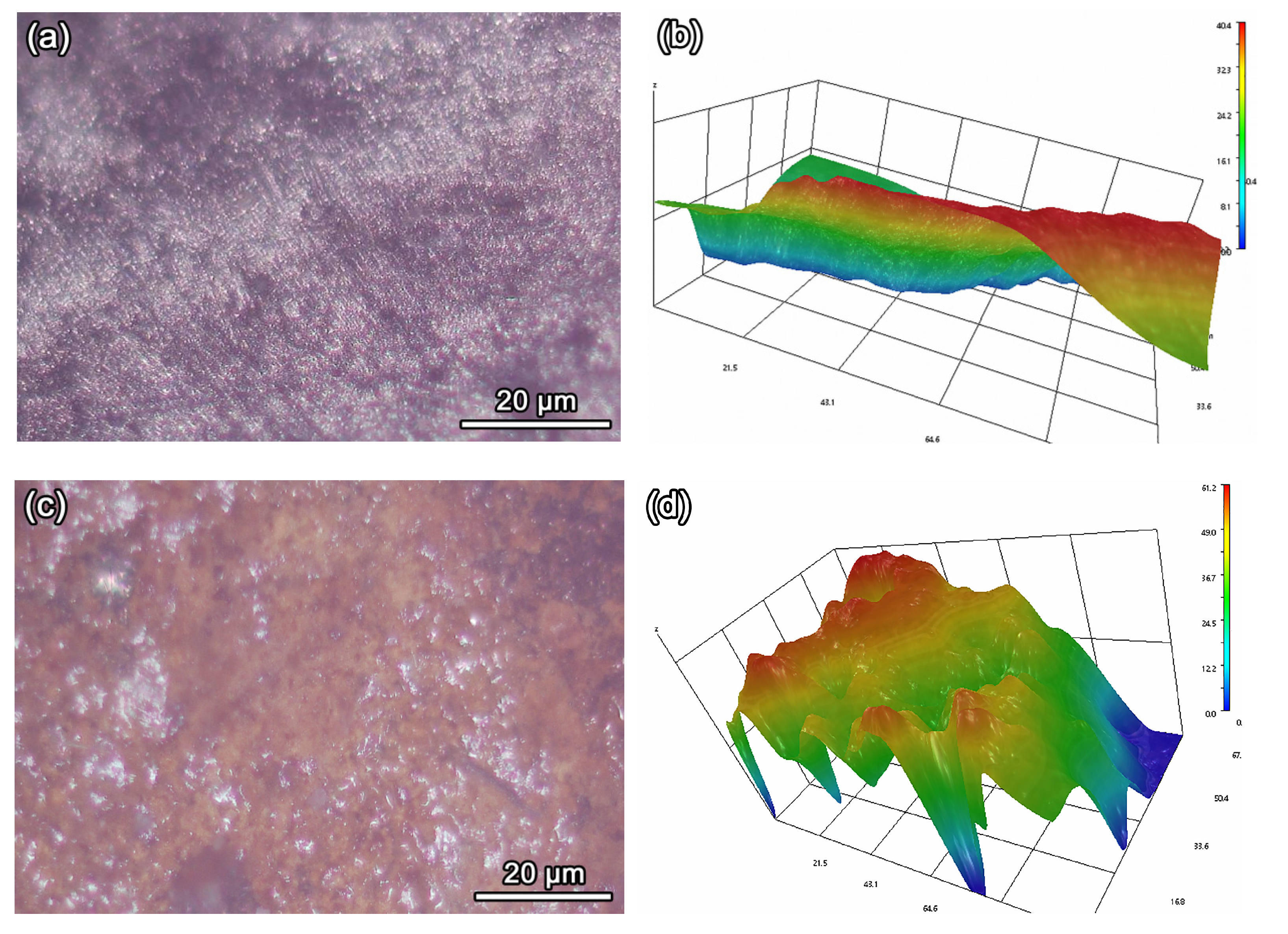
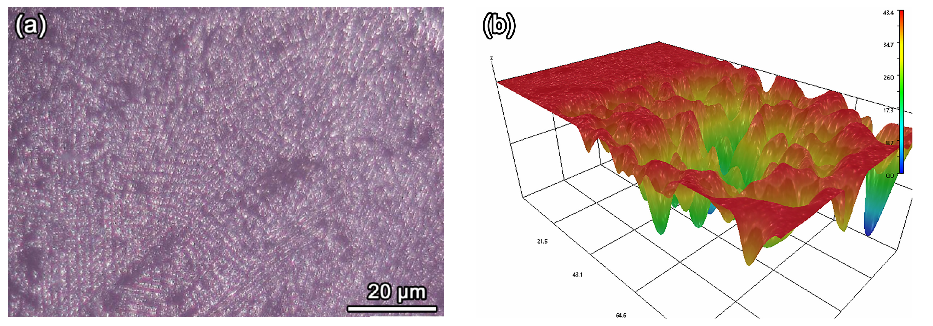
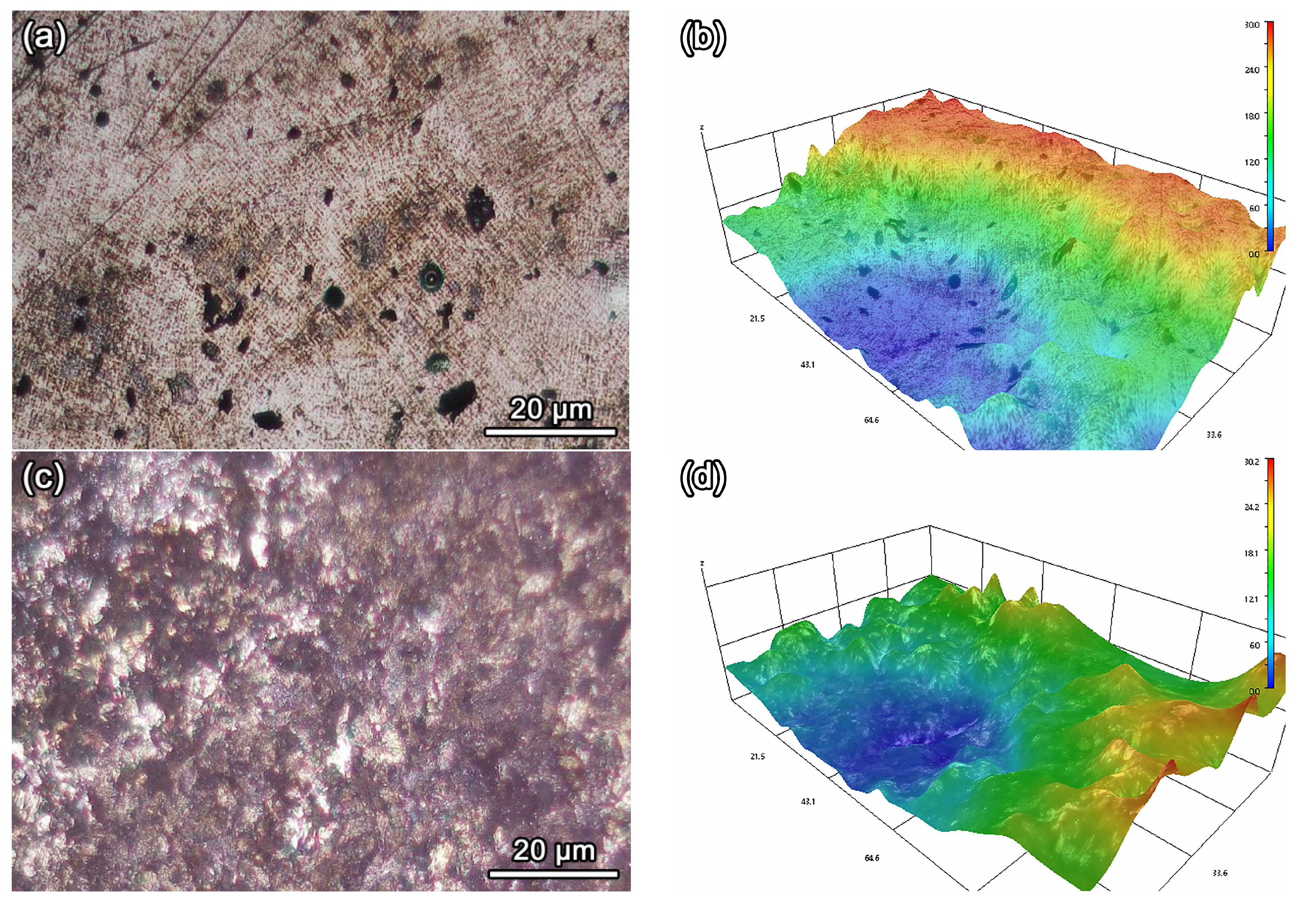
3.4. Analysis of Super Depth of Field and 3D Topological Morphology

To further investigate the corrosion characteristics of the HEA coating and the metal substrate following electrochemical corrosion, a super depth of field morphology observation was performed. The micrographs and their corresponding 3D topological images of the HEA coating and the metal substrate under various corrosive environments are shown in Figure 6, Figure 7 and Figure 8. As shown in Figure 6a, the surface of the HEA coating, subjected to corrosion in simulated seawater, displays black and white areas in an alternating pattern, which is indicative of significant variations in surface topography. The 3D topological image of the coating presented in Figure 6b further reveals significant variations in surface topography. Combined with the corrosion rate data listed in Table 4, it can be reasonably inferred that the observed significant variations are likely due to an accelerated corrosion rate of the coating in the simulated seawater environment. The morphology of the metal substrate after corrosion in simulated seawater is presented in Figure 6c, characterized by corrosion pits. Moreover, the 3D topological image of the substrate further evidences the occurrence of pitting corrosion in Figure 6d. These findings suggest that the metal substrate exhibits non-uniform corrosion characteristics. In comparison, the corrosion characteristics of the HEA coating and the metal substrate exhibit significant differences in simulated seawater.
Figure 7 presents the micrographs and their corresponding 3D topological images of the HEA coating and the metal substrate after electrochemical corrosion in a 3.5 wt.% NaCl solution. Comparing Figure 7a,b with Figure 7c,d, it is revealed that pitting corrosion is observed in both the HEA coating and BA substrate, indicating non-uniform corrosion characteristics in the 3.5 wt.% NaCl solution. Notably, the HEA coating exhibits a significant increase in the density of localized corrosion pits compared to the metal substrate. This variation in corrosion characteristics may be attributed to the distinct chemical compositions and microstructures between the HEA and the metal substrate. Coupled with the lower corrosion rate of the coating, as indicated in Table 4,it can be reasonably inferred that the HEA coating possesses good corrosion resistance in a 3.5 wt.% NaCl solution.
Figure 8 displays the micrographs and their corresponding 3D topological images of the HEA coating and the metal substrate subjected to electrochemical corrosion in a 5% HCl solution. By comparing Figure 8a,b with Figure 8c,d, it is clearly evident that both the current HEA coating and the metal substrate exhibit pitting corrosion, characterized by large localized corrosion pits. This may be attributed to the different corrosion reactions induced by the acidic environment of the HCl solution. In contrast to the features observed in Figure 7, these pitting characteristics are notably distinct. These characteristics are attributable to the lower corrosion rates of the HEA coating and the base alloy, as shown by in Table 4.
In summary, the electrochemical corrosion characteristics of HEA coating and the metal substrate across various media has been observed. In simulated seawater, the current Fe-based HEA coating exhibits low corrosion resistance compared to the metal substrate. However, the corrosion resistance of the current Fe-based HEA coating is superior to that of the substrate in 3.5 wt.% NaCl and 5% HCl solutions. Therefore, it is necessary to adopt appropriate protective strategies for different corrosive environments to ensure the stability and reliability of the HEA coatings in engineering applications.

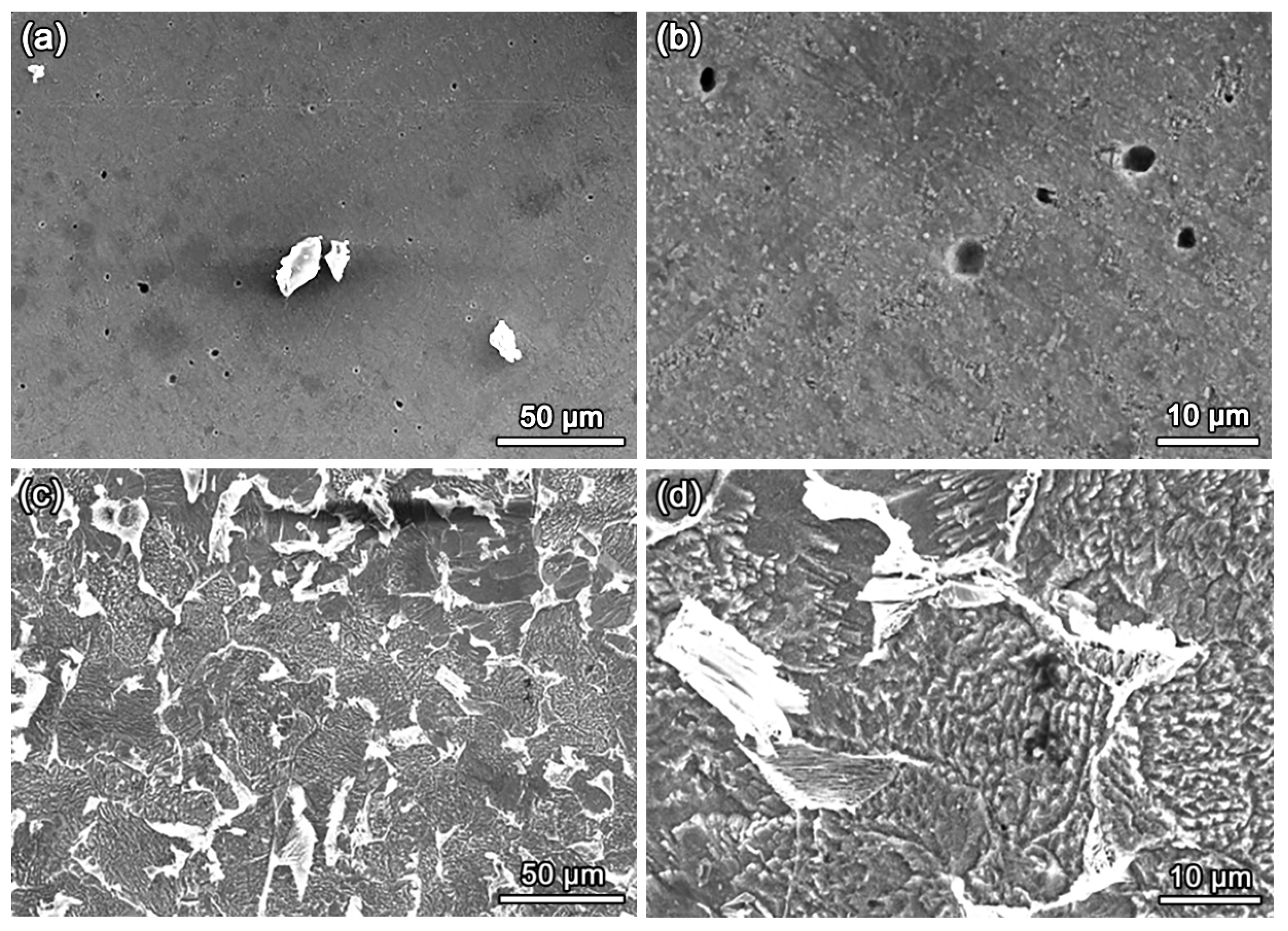
3.5. Analysis of Corrosion Morphology

To further investigate the corrosion mechanism, SEM observations were employed to examine the electrochemically corroded HEA coating and the metal substrate. Figure 9 presents the SEM images of the current HEA coatings and the metal substrate under the simulated seawater condition at room temperature. It can be seen that the corrosion surface of the current HEA coatings exhibits a uniformly distributed dendritic morphology, as depicted in Figure 9a,b. Moreover, it has also been observed that preferential corrosion occurs in the interdendritic regions. This corrosion morphology indicates that the current HEA coating displays relatively uniform corrosion characteristics. This is attributed to the single FCC structure of the HEA coating, which leads to more consistent formation of surface products. No significant pitting was observed on the HEA coating surface. In contrast, the morphology of the metal substrate exhibits a non-uniform corrosion characteristic, marked by the presence of deep, localized pits indicative of pitting corrosion. The above findings suggest that the HEA coatings exhibit more uniform and stable corrosion characteristics compared to the metal substrate.
Figure 10 and Figure 11 show the SEM images of the current HEA coatings and the metal substrate in a 3.5 wt.% NaCl solution and 5% HCl solution at room temperature. A uniformly distributed dendritic corrosion morphology was exhibited on the surface of the current HEA coatings, as presented in Figure 10a,b. This morphology is similar to the corrosion characteristics observed in SEM images of the HEA coating under the simulated seawater condition. In contrast, the morphology of the metal substrate appears relatively smooth, with no significant coarse corrosion marks and indistinct grain boundary corrosion characteristics. These characteristics differ from the corrosion surface observed in the metal substrate under simulated seawater conditions. The SEM images of the current HEA coating and the metal substrate after electrochemical corrosion in a 5% HCl solution were observed, and are depicted in Figure 11. It can be clearly seen that the surface of the current HEA coating displays uniform corrosion marks and exhibits pitting corrosion characteristics. Notably, there are no evidences of interdendritic corrosion on the coating surface, which differs from the corrosion characteristics observed in the SEM images of the current HEA coating under simulated seawater and the 3.5 wt.% NaCl solution. For the metal substrate, the characteristics of grain boundary corrosion and intergranular corrosion were observed, which differ from the corrosion characteristics observed in the metal substrate under simulated seawater and 3.5 wt.% NaCl conditions.
EDS maps of relevant elements (Fe, Co, Ni, Cr, Ti, O, Cl) for the FeCo1.5CrNi1.5Ti0.5 HEA coating were analyzed after exposure to simulated seawater, the 3.5 wt.% NaCl solution, and the 5% HCl solution. It can be seen that Cl and O2− are detected in the corroded samples, and they have significantly influenced the composition of the corrosion products. The percentage of O2− in the corrosion products is particularly high. However, the concentration of O2− in the corrosion products is similar in different corrosive environments after corrosion. These results indicated that the surfaces of the post-corroded specimens were covered by a corrosion oxide film. Combined with the SEM images of Figure 9, Figure 10 and Figure 11, pitting corrosion is evident on the surface of the present coating. Based on the pitting corrosion mechanism, it can be inferred that the thin passive film undergoes continuous breakdown and repair, resulting in the formation of preferential sites for corrosion. Once the passive film breaks down and a pit initiates, the pitting area may expand rapidly and grow steadily with increasing potential.
Compared to the theoretical atomic ratio, significant deviations in elemental content were found in the Fe-Co-Cr-Ni-Ti high-entropy alloys corroded under different environments. It was found that the atomic percentages of Fe, Co, and Cr were significantly lower than their theoretical values. The most significant reduction was observed in the Cr content, which decreased from the theoretical 30 at.% to a minimum of 9.26 at.% in the 3.5 wt.% NaCl solution. This indicates that selective dissolution of these elements likely occurred due to the formation of chromium-rich oxides or hydroxides. However, the atomic percentages of Ni and Ti remained relatively stable, indicating their superior corrosion resistance in the tested conditions.
Based on the dynamic polarization curves, the oxidation reaction occurs and leads to the ionization of HEA atoms into electrons and cations due to their potential differences. The metal cations could dissolve into the solution, and the reaction could be concluded at the anode [33]:
M M n +
where M represents the different alloying elements, such as Fe, Co, Cr, Ni, and Ti. n refers to the number of valence electrons of the cations present.These electrons migrate to the cathode and form hydroxide ions, which then combine with the metal cations to form the corresponding metal hydroxides. The metal oxides could be formed after dehydration. This reaction could be expressed as [33]
M n + + n O H M ( O H ) n
M ( O H ) n M O + n H 2 O
The oxides or hydroxides formed on the surface of the HEA coating, and a dense passive film was generated. This passivation film effectively could significantly inhibit the corrosion process.
In summary, the current Fe-based HEA coating exhibits varied resistance to Cl corrosion under different working conditions. Specifically, in simulated seawater and 3.5 wt.% NaCl solutions, this studied coating shows a preferential interdendritic corrosion characteristic and also presents a relatively uniform surface corrosion. However, in an acidic Cl corrosion condition, the HEA coating surfaces do not exhibit the same interdendritic corrosion characteristics. Instead, pitting corrosion was the main characteristic. Therefore, these findings suggest that this composition of the HEA coating is more suitable for resisting acidic Cl corrosion conditions.

4. Conclusions

In this study, a dense FeCo1.5CrNi1.5Ti0.5 high-entropy alloy coating was successfully prepared on a 1Cr8Ni9Ti alloy substrate using laser cladding technology. The crystal structure and microstructural morphology of the coating were characterized by XRD and SEM. The corrosion resistance was systematically evaluated across three distinct corrosive environments: simulated seawater, a 3.5 wt.% NaCl solution, and a 5% HCl solution. Furthermore, the electrochemical behavior of this coating was studied in different corrosive environments by an electrochemical workstation, accompanied by super depth of field observation, and 3D topological images. The following conclusions can be drawn:
  • A single-phase face-centered cubic (FCC) structure HEA coating was successfully prepared using laser cladding technology.
  • The studied Fe-based HEA coating has a small grain size, approximately 10.7 ± 0.25 by SEM observation.
  • The Fe-based HEA coating exhibits superior corrosion resistance in simulated seawater and 3.5 wt.% NaCl solutions but presents lower resistance in a 5% HCl solution compared to the metal substrate.
  • The surface of the current Fe-based HEA coating shows preferential interdendritic corrosion in simulated seawater and 3.5 wt.% NaCl solutions, whereas it displays a more pronounced pitting characteristic in a 5% HCl solution.

Author Contributions

Methodology, S.T., R.L. and D.C.; Resources, C.W. and J.L.; Supervision, S.Y.; Project administration, S.W. All authors have read and agreed to the published version of the manuscript.

Funding

This research was funded by the CNPC Science and Technology Project (Research and Development of Corrosion Resistant Materials for Extreme Environments, No. 2023ZZ11-02).

Institutional Review Board Statement

Not applicable.

Informed Consent Statement

Not applicable.

Data Availability Statement

Data are contained within the article.

Conflicts of Interest

Authors Siqi Tian, Renjie Liu, Dengya Chen were employed by the company PetrChina Xinjiang Oilfield Company. Author Jing Li was employed by the company Xi’an Beifang Qinghua Mechanical and Electrical Co., Ltd. The remaining authors declare that the research was conducted in the absence of any commercial or financial relationships that could be construed as a potential conflict of interest.

References

  1. Balaji, V.; Anthony, X.M. Development of high entropy alloys (HEAs): Current trends. Heliyon 2024, 10, 26464. [Google Scholar]
  2. Ye, Y.F.; Wang, Q.; Lu, J.; Liu, C.T.; Yang, Y. High-entropy alloy: Challenges and prospects. Mater. Today 2016, 19, 349–362. [Google Scholar] [CrossRef]
  3. Takeuchi, A.; Wada, T.; Nagase, T.; Amiya, K. Ultra-high mixing entropy alloys with single bcc, hcp, or fcc structure in Co–Cr–V–Fe–X(X=Al, Ru, or Ni) systems designed with structure-dependent mixing entropy and mixing enthalpy of constituent binary equiatomic alloys. Mater. Trans. 2022, 63, 835–844. [Google Scholar] [CrossRef]
  4. Hu, Q.; Guo, S.; Wang, J.M.; Yan, Y.H.; Chen, S.S.; Lu, D.P.; Liu, K.M.; Zou, J.Z.; Zeng, X.R. Parametric study of amorphous high-Entropy alloys formation from two new perspectives: Atomic radius modification and crystalline structure of alloying elements. Sci. Rep. 2017, 7, 39917. [Google Scholar] [CrossRef]
  5. Li, T.X.; Wang, S.D.; Lu, Y.P.; Cao, Z.Q.; Wang, T.M.; Li, T.J. Research progress and prospect of high-entropy alloy materials. Strateg. Study CAE 2023, 25, 170–181. [Google Scholar] [CrossRef]
  6. George, E.P.; Curtin, W.A.; Tasan, C.C. High entropy alloys: A focused review of mechanical properties and deformation mechanisms. Acta Mater. 2020, 188, 435–474. [Google Scholar] [CrossRef]
  7. Fu, Y.; Li, J.; Luo, H.; Du, C.W.; Li, X.G. Recent advances on environmental corrosion behavior and mechanism of high-entropy alloys. J. Mater. Sci. Technol. 2021, 80, 217–233. [Google Scholar] [CrossRef]
  8. Zhang, W.; Chabok, A.; Kooi, B.J.; Pei, Y.T. Additive manufactured high entropy alloys: A review of the microstructure and properties. Mater. Des. 2022, 220, 110875. [Google Scholar] [CrossRef]
  9. Arif, Z.U.; Khalid, M.Y.; Rehman, E.U.; Ullah, S.; Atif, M.; Tariq, A. A review on laser cladding of high-entropy alloys, their recent trends and potential applications. J. Manuf. Process. 2021, 68, 225–273. [Google Scholar] [CrossRef]
  10. Yang, C.; Jing, C.N.; Fu, T.L.; Lin, T.; Guo, W.M.; Liu, N.N. Effect of CeO2 on the microstructure and properties of AlCoCrFeNi2.1 laser cladding coatings. J. Alloys Compd. 2024, 976, 172948. [Google Scholar] [CrossRef]
  11. Guo, Y.F.; Zhu, J.Q.; Cao, J.J.; Qiu, Z.G.; Chang, C.; Yan, X.C.; Yin, S.; Liu, M. Pitting corrosion mechanism of BCC+FCC dual-phase structured laser cladding FeCoCrNiAl0.5Ti0.5 HEAs coating. J. Alloys Compd. 2024, 980, 173643. [Google Scholar] [CrossRef]
  12. Ren, X.Y.; Sun, W.L.; Tian, S.; Zhu, C.J.; Qin, M.J.; Yang, Y.L.; Wu, W.N. Tribological and electrochemical behaviors of FeCoNiCrMox HEA coatings prepared by internal laser cladding on 316L steel tube. Mater. Charact. 2024, 211, 113906. [Google Scholar] [CrossRef]
  13. Wan, S.M.; Cui, X.F.; Liu, K.J.; Jin, G.; Wang, S.; Zhao, Y.; Li, J.; Yang, Y.Y.; Guan, Y.J. Preparation of AlTiVNiCu/Cu–Al gradient functional coating via laser cladding for enhanced wear and corrosion resistance of MgLi alloy. Surf. Coat. Technol. 2023, 475, 130137. [Google Scholar] [CrossRef]
  14. He, R.; Wu, M.P.; Cui, C.; Jie, D.D.; Miao, X.J. Laser cladding manufacturing of TiC + TiBx reinforced FeNiCrTi0.3Al0.3 high entropy alloy composite coating: Effects on corrosion and tribology. J. Alloys Compd. 2024, 970, 172631. [Google Scholar] [CrossRef]
  15. Zhao, T.; Wang, L.; Zhang, S.; Zhang, C.H.; Sun, X.Y.; Chen, H.T.; Bai, X.L.; Wu, C.L. Effect of synergistic cavitation erosion-corrosion on cavitation damage of CoCrFeNiMn high entropy alloy layer by laser cladding. Surf. Coat. Technol. 2023, 472, 129940. [Google Scholar] [CrossRef]
  16. Chou, Y.L.; Yeh, J.W.; Shih, H.C. The effect of molybdenum on the corrosion behaviour of the high-entropy alloys Co1.5CrFeNi1.5Ti0.5Mox in aqueous environments. Corros. Sci. 2010, 52, 2571–2581. [Google Scholar] [CrossRef]
  17. Moravcik, I.; Cizek, J.; Zapletal, J.; Kovacova, Z.; Vesely, J.; Minarik, P.; Kitzmantel, M.; Neubauer, E.; Dlouhy, I. Microstructure and mechanical properties of Ni1.5Co1.5CrFeTi0.5 high entropy alloy fabricated by mechanical alloying and spark plasma sintering. Mater. Des. 2017, 119, 141–150. [Google Scholar] [CrossRef]
  18. Zhang, Y.; Zuo, T.T.; Tang, Z.; Gao, M.C.; Dahmen, K.A.; Liaw, P.K.; Lu, Z.P. Microstructures and properties of high-entropy alloys. Prog. Mater. Sci. 2014, 61, 1–93. [Google Scholar] [CrossRef]
  19. George, E.P.; Raabe, D.; Ritchie, R.O. High-entropy alloys. Nat. Rev. Mater. 2019, 4, 515–534. [Google Scholar] [CrossRef]
  20. Liu, L.L.; Zhang, J.L.; Zhang, Q.; Zhai, C.S.; Zheng, H.X. Computational insights into gas atomization of FeCoNiCrMoBSi high-entropy alloy: From droplet formation to rapid solidification. Int. J. Heat Mass Transfer. 2024, 228, 125628. [Google Scholar] [CrossRef]
  21. Lentzaris, K.; Poulia, A.; Georgatis, E.; Lekatou, A.G.; Karantzalis, A.E. Analysis of microstructure and sliding wear behavior of Co1.5CrFeNi1.5Ti0.5 high-entropy alloy. J. Mater. Eng. Perform. 2018, 27, 5177–5186. [Google Scholar] [CrossRef]
  22. Liu, Z.Y.; Zhao, D.D.; Wang, P.; Yan, M.; Yang, C.; Chen, Z.W.; Lu, J.; Lu, Z.P. Additive manufacturing of metals: Microstructure evolution and multistage control. J. Mater. Sci. Technol. 2022, 100, 224–236. [Google Scholar] [CrossRef]
  23. Ya, W.; Pathiraj, B.; Liu, S.J. 2D modelling of clad geometry and resulting thermal cycles during laser cladding. J. Mater. Process. Technol. 2016, 230, 217–232. [Google Scholar] [CrossRef]
  24. Shin, D.; Shyam, A.; Lee, S.; Yamamoto, Y.; Haynes, J.A. Solute segregation at the Al/θ′-Al2Cu interface in Al-Cu alloys. Acta Mater. 2017, 141, 327–340. [Google Scholar] [CrossRef]
  25. Jin, Z.J.; An, F.C.; Li, S.X.; Cui, Z.Y.; Lu, W.J.; Lu, S.Y. Effect of annealing temperature on the microstructure evolution and corrosion behavior of Carbon-interstitial FeMnCoCrNi high-entropy alloys. Corros. Sci. 2024, 228, 111813. [Google Scholar] [CrossRef]
  26. Luo, H.; Wang, X.Z.; Dong, C.F.; Xiao, K.; Li, X.G. Effect of cold deformation on the corrosion behaviour of UNS S31803 duplex stainless steel in simulated concrete pore solution. Corros. Sci. 2017, 124, 178–192. [Google Scholar] [CrossRef]
  27. McCafferty, E. Validation of corrosion rates measured by the Tafel extrapolation method. Corros. Sci. 2005, 47, 3202–3215. [Google Scholar] [CrossRef]
  28. Yao, J.Y.; Serrano, L.B.; Santos, S.F.; Cardoso, K.R. Microstructure and corrosion behavior of the Ti-V-Cr-Nb high-entropy alloys in 3.5wt% NaCl solution. Corros. Sci. 2023, 218, 111149. [Google Scholar] [CrossRef]
  29. Gu, Z.; Mao, P.; Gou, Y.F.; Chao, Y.; Xi, S.Q. Microstructure and properties of MgMoNbFeTi2Yx high entropy alloy coatings by laser cladding. Surf. Coat. Technol. 2020, 402, 126303. [Google Scholar] [CrossRef]
  30. Cao, H.B.; Hou, G.L.; Xu, T.C.; Ma, J.K.; Wan, H.Q.; An, Y.L.; Zhou, H.D.; Chen, J.M. Effect of seawater temperature on the corrosion and cavitation erosion-corrosion resistance of Al10Cr28Co28Ni34 high-entropy alloy coating. Corros. Sci. 2024, 228, 111822. [Google Scholar] [CrossRef]
  31. Cheng, J.B.; Liang, X.B.; Xu, B.S. Effect of Nb addition on the structure and mechanical behaviors of CoCrCuFeNi high-entropy alloy coatings. Surf. Coat. Technol. 2014, 240, 184–190. [Google Scholar] [CrossRef]
  32. Mao, A.Q.; Ding, P.P.; Quan, F.; Zhang, T.C.; Ran, X.Q.; Li, Y.B.; Jin, X.; Gu, X.L. Effect of aluminum element on microstructure evolution and properties of multicomponent Al-Co-Cr-Cu-Fe-Ni nanoparticles. J. Alloys Compd. 2018, 735, 1167–1175. [Google Scholar] [CrossRef]
  33. Feng, H.; Li, H.B.; Dai, J.; Han, Y.; Qu, J.D.; Jiang, Z.H.; Zhao, Y.; Zhang, T. Why CoCrFeMnNi HEA could not passivate in chloride solution?—A novel strategy to significantly improve corrosion resistance of CoCrFeMnNi HEA by N-alloying. Corros. Sci. 2022, 204, 110396. [Google Scholar]
Figure 1. The coating sample and the XRD pattern. (a) The macroscopic sample prepared by laser cladding; the inset shows the OM of the lateral surface of the coating; (b) the XRD pattern of FeCo1.5CrNi1.5Ti0.5 HEA powder and coating.
Coatings 14 01608 g001
Figure 2. Microstructure of FeCo1.5CrNi1.5Ti0.5 HEA coating at different multiples: (a) 2000×; (b) 5000×.
Coatings 14 01608 g002
Figure 3. SEM image and the corresponding elemental distribution maps of the FeCo1.5CrNi1.5Ti0.5 HEA coating.
Coatings 14 01608 g003
Figure 4. OCP and polarization curves of the FeCo1.5CrNi1.5Ti0.5 HEA coating and the metal substrate at normal temperature under different working conditions: (a) OCP curves; (b) simulated seawater; (c) 3.5 wt.% NaCl solution; (d) 5% HCl solution.
Coatings 14 01608 g004
Figure 5. EIS results and equivalent circuits of the FeCo1.5CrNi1.5Ti0.5 HEA coating in simulated seawater, a 3.5 wt.% NaCl solution, and a 5% HCl solution. (a) Nyquist plots; (b) Bode plots; (c) the equivalent circuit used for simulated seawater and the 3.5 wt.% NaCl solution; (d) the equivalent circuit used for the 5% HCl solution.
Coatings 14 01608 g005
Figure 6. Micrographs and the corresponding 3D topological images of FeCo1.5CrNi1.5Ti0.5 HEA coating and the metal substrate after electrochemical testing in simulated seawater. (a) Super-depth morphology of the HEA coating; (b) 3D topological image of the HEA coating; (c) super-depth morphology of the metal substrate; (d) 3D topological image of the metal substrate.
Coatings 14 01608 g006
Figure 7. Micrographs and the corresponding 3D topological images of the FeCo1.5CrNi1.5Ti0.5 HEA coating and the metal substrate after electrochemical testing in a 3.5 wt.% NaCl solution. (a) Super-depth morphology of the HEA coating; (b) 3D topological image of the HEA coating; (c) super-depth morphology of the metal substrate; (d) 3D topological image of the metal substrate.
Coatings 14 01608 g007aCoatings 14 01608 g007b
Figure 8. Micrographs and the corresponding 3D topological images of the FeCo1.5CrNi1.5Ti0.5 HEA coating and the metal substrate after electrochemical testing in a 5% HCl solution. (a) Super-depth morphology of the HEA coating; (b) 3D topological image of the HEA coating; (c) super-depth morphology of the metal substrate; (d) 3D topological image of the metal substrate.
Coatings 14 01608 g008
Figure 9. SEM images of the FeCo1.5CrNi1.5Ti0.5 HEA coating and the metal substrate after electrochemical testing in simulated seawater. (a) HEA coating, 500×; (b) HEA coating, 2000×; (c) the metal substrate, 500×; (d) the metal substrate, 2000×.
Coatings 14 01608 g009
Figure 10. SEM images of the FeCo1.5CrNi1.5Ti0.5 HEA coating and the metal substrate after electrochemical testing in a 3.5 wt.% NaCl solution. (a) HEA coating, 500×; (b) HEA coating, 2000×; (c) the metal substrate, 500×; (d) the metal substrate, 2000×.
Coatings 14 01608 g010
Figure 11. SEM images of the FeCo1.5CrNi1.5Ti0.5 HEA coating and the metal substrate after electrochemical testing in a 5% HCl solution. (a) HEA coating, 500×; (b) HEA coating, 2000×; (c) the metal substrate, 500×; (d) the metal substrate, 2000×.
Coatings 14 01608 g011
Table 1. Chemical composition (g/L) of simulated seawater.
Chemical ReagentNaClMgCl2Na2SO4CaCl2KClNaHCO3HBrHBO3SrCl2NaF
Concentration24.53011.1104.0901.1600.6850.2010.1010.0270.0280.003
Table 2. Dynamic electrochemical polarization curve parameters of the FeCo1.5CrNi1.5Ti0.5 HEA coating and metal substrate under different corrosive environments.
Corrosive EnvironmentsWorking ElectrodeCorrosion Potential (V)Current Density
(A·cm−2)
Corrosion Rate (μm·Year−1)
Simulated seawaterFeCo1.5CrNi1.5Ti0.5
HEA coating
−0.9907.94 × 10−5925
Substrate−0.9422.12 × 10−5246
3.5 wt% NaCl
solution
FeCo1.5CrNi1.5Ti0.5
HEA coating
−0.8931.98 × 10−5936
Substrate−0.9021.47 × 10−5171
5% HCl
solution
FeCo1.5CrNi1.5Ti0.5
HEA coating
−0.3310.35 × 10−550.3
Substrate−0.4523.31 × 10−5385
Simulated seawaterMgMoNbFeTi2
HEA coating [29]
−1.2527.23 × 10−5-
Simulated seawaterAl10Cr28Co28Ni34
HEA coating [30]
−0.86210.21 × 10−5-
3.5 wt% NaCl
solution
FeCoCrNiAl0.5Ti0.5
HEA coating [11]
−0.7584.39 × 10−5960
3.5 wt% NaCl
solution
FeCoNiCrMo0.4
HEA coating [12]
−0.9665.53 × 10−5-
6M HCl
solution
CoCrCuFeNiNb
HEA coating [31]
−0.3978.93 × 10−5-
10% HCl
solution
AlCoCrCuFeNi
HEA coating [32]
−0.6570.315-
Table 3. Equivalent circuit parameters for the fitting EIS data.
SpecimenSolutionRs
(Ω⋅cm2)
Rf
(Ω⋅cm2)
CPEf
Y0−1sncm−2)
n1Rct
(Ω⋅cm2)
CPEdl
Y0−1sncm−2)
n2Rp
(Ω⋅cm2)
FeCo1.5CrNi1.5Ti0.5 HEA coatingsimulated seawater15.3020.808.47 × 10−40.9212.4 × 1032.58 × 10−40.9112,420.80
3.5 wt.% NaCl solution13.4042.208.30 × 10−40.929.23 × 1032.58 × 10−40.879272.20
5% HCl solution1.79134.001.28 × 10−41.130.283 × 1030.15 × 10−40.86417.00
Table 4. Chemical compositions of FeCo1.5CrNi1.5Ti0.5 HEA coating after exposure to simulated seawater, 3.5 wt.% NaCl solution, and 5% HCl solution, obtained by EDS.
Corrosive EnvironmentsFe (at%)Co (at%)Ni (at%)Cr (at%)Ti (at%)Cl (at%)O2− (at%)
Simulated seawater11.2517.0321.1210.2710.954.4024.97
3.5 wt% NaCl solution10.7317.8421.779.2611.833.3025.54
5% HCl solution10.5318.0818.0910.717.403.8228.36
Theoretical atomic ratio2030203010--
Disclaimer/Publisher’s Note: The statements, opinions and data contained in all publications are solely those of the individual author(s) and contributor(s) and not of MDPI and/or the editor(s). MDPI and/or the editor(s) disclaim responsibility for any injury to people or property resulting from any ideas, methods, instructions or products referred to in the content.

