Article

Facile Preparation of Composite Coatings with Incorporated 13X Zeolite and CeO2

by
Kristina Mojsilović
1,
Nenad Tadić
1,
Srna Stojanović
2,
Ljiljana Damjanović-Vasilić
2 and
Rastko Vasilić
1,*
1
Faculty of Physics, University of Belgrade, Studentski trg 12-16, 11000 Belgrade, Serbia
2
Faculty of Physical Chemistry, University of Belgrade, Studentski trg 12-16, 11000 Belgrade, Serbia
*
Author to whom correspondence should be addressed.
Coatings 2024, 14(12), 1516; https://doi.org/10.3390/coatings14121516
Submission received: 1 November 2024 / Revised: 28 November 2024 / Accepted: 29 November 2024 / Published: 30 November 2024

Abstract

:
One-step methods for the formation of efficient thin-film catalysts for wastewater treatment under the sunlight spectrum is a topic of interest for many research groups. This article reports on the facile preparation of photocatalytic coatings by plasma electrolytic oxidation processing from 0.01 M sodium tungstate electrolyte solution containing both 13X zeolite and CeO2. Obtained coatings are characterized with respect to their surface morphology, chemical and phase composition, and possible application as photocatalysts in photodegradation of organic pollutants. All prepared coatings contain elements originating from both substrate and electrolyte solution. Addition of 1 g/L of 13X zeolite and CeO2 in various concentrations to electrolyte solution results in increased photodecomposition of model organic pollutant. The highest photodegradation under simulated sunlight is observed for coatings formed in 0.01 M sodium tungstate with addition of 1 g/L of 13X zeolite and 1 g/L of CeO2, reaching 50% after 6 h of irradiation.

1. Introduction

Amidst the growing challenges posed by climate change, water scarcity has emerged as a critical issue. The need to remove contaminants from wastewater and conserve water resources is increasingly urgent, prompting researchers worldwide to seek innovative solutions [1]. One promising approach in wastewater treatment is photocatalytic degradation, which utilizes irradiation to decompose pollutants. This advanced technology has gained significant attention, leading to the development of numerous semiconductor-based photocatalysts [2,3,4,5]. It is well established that the efficiency of photocatalytic activity in semiconducting photocatalysts depends on light absorption characteristics, which are directly linked to their band gap energy and the rate at which photogenerated electron–hole pairs recombine [6]. To enhance these properties, one effective strategy is to introduce additional energy levels within the semiconductor’s band gap. This modification reduces the band gap, enabling the semiconductor to absorb light at longer wavelengths, thereby improving its photocatalytic efficiency under a wider range of irradiation conditions [7].
The photocatalytic degradation process is typically accomplished in batch slurry photoreactors using particle suspensions [8]. Unfortunately, slurry reactors exhibit a number of practical and economical drawbacks. The main drawback of such photoreactors is the necessity of separation of particles from treated wastewater after the process is finished. The separation step could be avoided by supporting those particles on a suitable carrier, i.e., by forming stable oxide coatings directly on the surfaces of metal sheets. Solid oxide coatings are better suitable than powders in industrial applications, since immobilized photocatalysts simplify the technology via avoiding the separation step and recirculation. On the other hand, immobilized oxide coatings usually have less developed surface area available for photocatalysis resulting in reduced efficiency of photocatalytic processing [9]. To enhance the efficiency of the process, significant efforts have been focused on the synthesis of composite photocatalysts, where plasma electrolytic oxidation (PEO) proved to be an appropriate tool for production of stable oxide coatings [10].
PEO is a proven industrial surface treatment process that converts the surface of various metals (Al, Mg, Ti, Zn and their alloys) to their oxides [11]. A number of published articles is focused on the incorporation of particles into oxide coatings during the PEO treatment [12,13]. Generally, addition of particles to electrolyte used for PEO processing results in the formation of thicker and denser oxide coatings, thus increasing their wear and corrosion resistance. The addition of particles to PEO processing electrolyte solution also influences the onset of dielectric breakdown, chemical and phase composition of obtained oxide coatings and enhances luminescent and photocatalytic properties [11].
Different research groups focused their efforts on possible functional additives to PEO electrolytes. Among various additives used for PEO processing, so-called nanocontainers (such as zeolites, layered double hydroxides and/or metal organic frameworks), play an important role because they can be loaded with various species and subsequently incorporated into PEO coatings [14,15,16]. Zeolites are microporous crystalline materials with a three-dimensional framework composed of pores and channels of regular dimensions. The metal ions in the pore structure can be easily replaced by other cations through ion exchange process [17]. Regardless the fact that zeolites are mainly used as adsorbents and heterogeneous catalysts, it has been shown that they could enhance the efficiency and selectivity of photocatalysts either by photoactivating the zeolite framework or by encapsulating nano-sized semiconductor oxides [18,19,20].
Previously published papers investigated the incorporation of zeolites into oxide coatings through PEO processing and showed that Ce-loaded zeolites feature respectable photocatalytic activity which is combined with lower degradation of samples in aggressive environment [14,21,22]. Although the type of zeolite incorporation (inert or reactive) remained unclear in those studies, Al Abri et al. pointed at inert incorporation of Ce-loaded zeolites in so-called soft sparking mode [23]. In all mentioned works, zeolites are loaded with Ce-ions through simple but time consuming ion exchange process.
The main goal of this study is to propose a new method for co-deposition of zeolites and CeO2 from electrolyte in order to make less expensive photocatalytic materials. In other words, the idea is to employ zeolites as a support for photoactive species simplifying the photocatalyst preparation procedure and possibly enhancing the efficiency of photocatalytic decomposition of model organic pollutant. Photocatalytic coatings obtained by PEO processing from electrolyte solution containing both 13X zeolite and CeO2 are formed and characterized with respect to their surface morphology, chemical and phase composition, and possible application as photocatalysts.

2. Materials and Methods

Aluminum samples (approximate surface area of 3 cm2) were cut from aluminum 1050 alloy foil and used as the anode. A stainless steel sheet of approx. 20 cm2 was used as the cathode in all experiments. The zeolite used in this work was synthetic FAU-type 13X zeolite (Na87[Al87Si105O384], Si/Al = 1.2) produced by Union Carbide, Houston, TX, USA. The average particle size of zeolite powders used in this study is (2.5 ± 0.5) μm, as estimated from SEM micrographs of zeolite powder. Surface area of 13X zeolite used in this study is 629.3 m2/g.
PEO processing was performed in an electrolytic cell containing water solution of 0.01 M sodium tungstate (Na2WO4∙2H2O), which was used as a supporting electrolyte with additions of 1 g/L 13X zeolite with various amounts of CeO2 powder (Table 1). A source of CeO2 was CeO2 powder (99.9% purity, Johnson Matthey-Alfa Product, Abingdon, UK). Spherically shaped CeO2 particles have two-modal particle size distribution (2 µm and 20 µm). Measured surface area of CeO2 powder used in this study is 3.96 m2/g, while average crystallite size was 52 nm. The electrolyte was prepared using double distilled and deionized water. During the processing electrolyte solution circulated through chamber-reservoir system and the temperature of the electrolyte was kept under 25 °C. The PEO was conducted under a constant current density of 50 mA/cm2 during 10 min using Consort EV 261 DC power source (Tutnhout, Belgium). Following the formation of PEO coatings, prepared coatings were rinsed in distilled water and dried. The evolution of the voltage during the PEO process was monitored using Tektronix (Brachnell, UK) TDS 2022 digital storage oscilloscope and a high voltage probe.
A scanning electron microscope (SEM) JEOL JSM-6610 LV equipped with energy dispersive X-ray spectroscopy (EDS) Xplore 30 (Oxford Instruments, Tubney Woods, Abingdon, UK) was used to characterize morphology and chemical composition of formed oxide coatings. Roughness and porosity were estimated from SEM micrographs using ImageJ software v1.54i (LOCI University of Wisconsin, Madison, WI, USA).
A Rigaku (Tokyo, Japan) Ultima IV diffractometer with a Ni-filtered CuKα radiation source was used for crystal phase identification. Crystallographic data were collected in the Bragg–Brentano mode, in 2θ range from 20° to 80° with a scanning rate of 2°/min. High-resolution diffraction patterns are recorded in 2θ range from 22° to 26°, with a scanning rate of 0.05°/min.
Photoluminescence (PL) spectral measurements were performed on a Horiba Jobin Yvon (Piscataway, NJ, USA) Fluorolog FL3-22 spectrofluorometer at room temperature, with a 450 W xenon lamp as the excitation light source, in the range from 300 nm to 500 nm.
Photocatalytic activity of coatings formed in this study was inspected by photodecomposition of methyl orange (MO) at room temperature. Formed oxide coatings (approx. 1.5 cm2 exposed to irradiation) were submerged into 10 mL of 8 mg/L aqueous MO solution a by placing them on a perforated holder inside of a jacketed 50 mL glass beaker with a magnetic stirrer underneath. Before the onset of photocatalytic testing, the solution and the catalyst were magnetically stirred in the absence of light until adsorption–desorption equilibrium was reached. After 30 min in the dark we assumed that equilibrium is reached and MO solution was illuminated using a lamp that simulates the solar spectrum (300 W, Osram Vitalux lamp, Munich, Germany). The lamp was positioned 25 cm above the top surface of the solution. Every hour, a fixed amount (1 mL) of photodegraded solution was taken out of the beaker to measure the absorption utilizing UV–Vis spectrophotometer Agilent Carry 60 (Santa Clara, CA, USA). After each measurement the aliquot that was taken out of the beaker was returned. Prior to the photocatalytic experiments, MO solution was tested for photolysis in the absence of the photocatalyst and the lack of change in the MO concentration after 6 h of irradiation revealed that the MO was stable under applied conditions and that degradation was only due to the presence of the photocatalyst.

3. Results

During the formation of PEO coatings, voltage evolution was recorded revealing that the coating preparation process follows the typical voltage–time evolution [24]. The time evolution of anodization voltage during PEO, under current control, in electrolyte solutions used in this work is shown in Figure 1. The first 90 s of the PEO processing are characterized by linear voltage increase with time. As discussed in many previously published articles, this part of the PEO process can be related to conventional anodizing, i.e., during this part of the PEO process a relatively uniform increase of the oxide barrier layer occurs [10,11,24]. Linear thickening of formed oxide coating ends with the onset of dielectric breakdown, which can be observed as a bending of the voltage versus time curve. Additional voltage increase results in the appearance of visible microdischarges across the sample’s surface. As can be seen in Figure 1, addition of zeolite and CeO2 did not affect the voltage evolution, although the final PEO voltage did increase. Since the breakdown is related to the conductivity (resistivity) of the electrolyte solution, it is expected that the breakdown voltage values do not change significantly as a consequence of similar conductivity values of all electrolytes used in this study (Table 1). Unchanged voltage–time response suggests that the deposition mechanism remains the same, while a slight voltage increase can be attributed to the addition of pure 13X zeolite and CeO2 powder to supporting electrolyte solution.

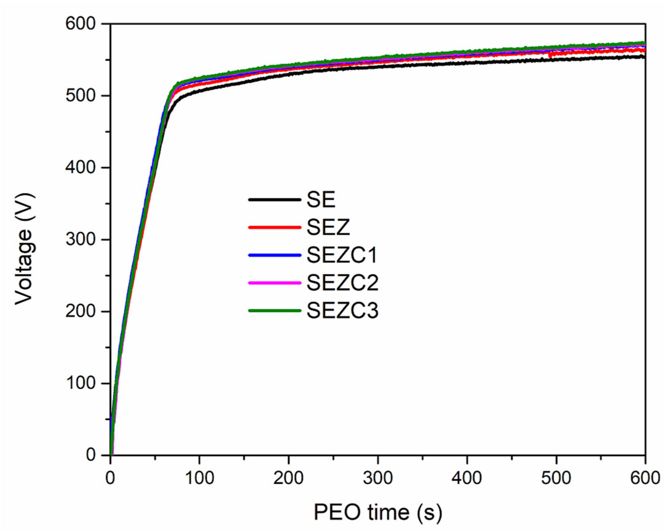
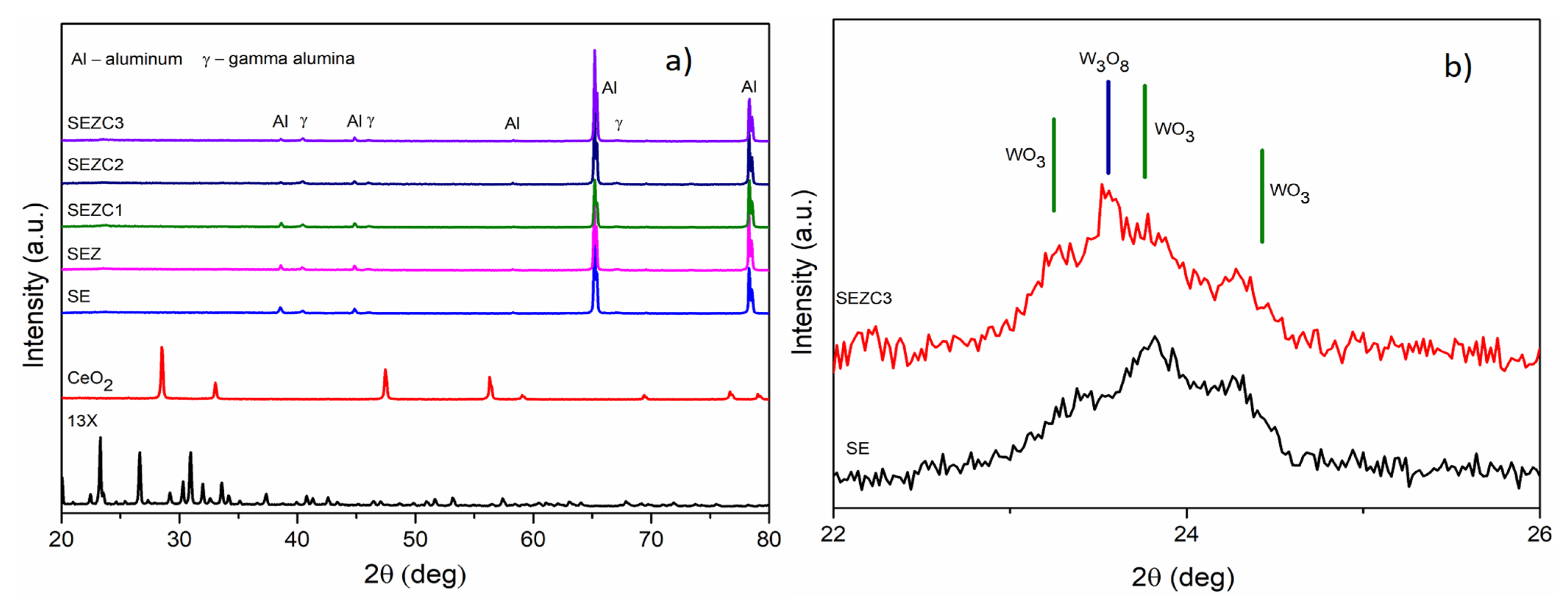
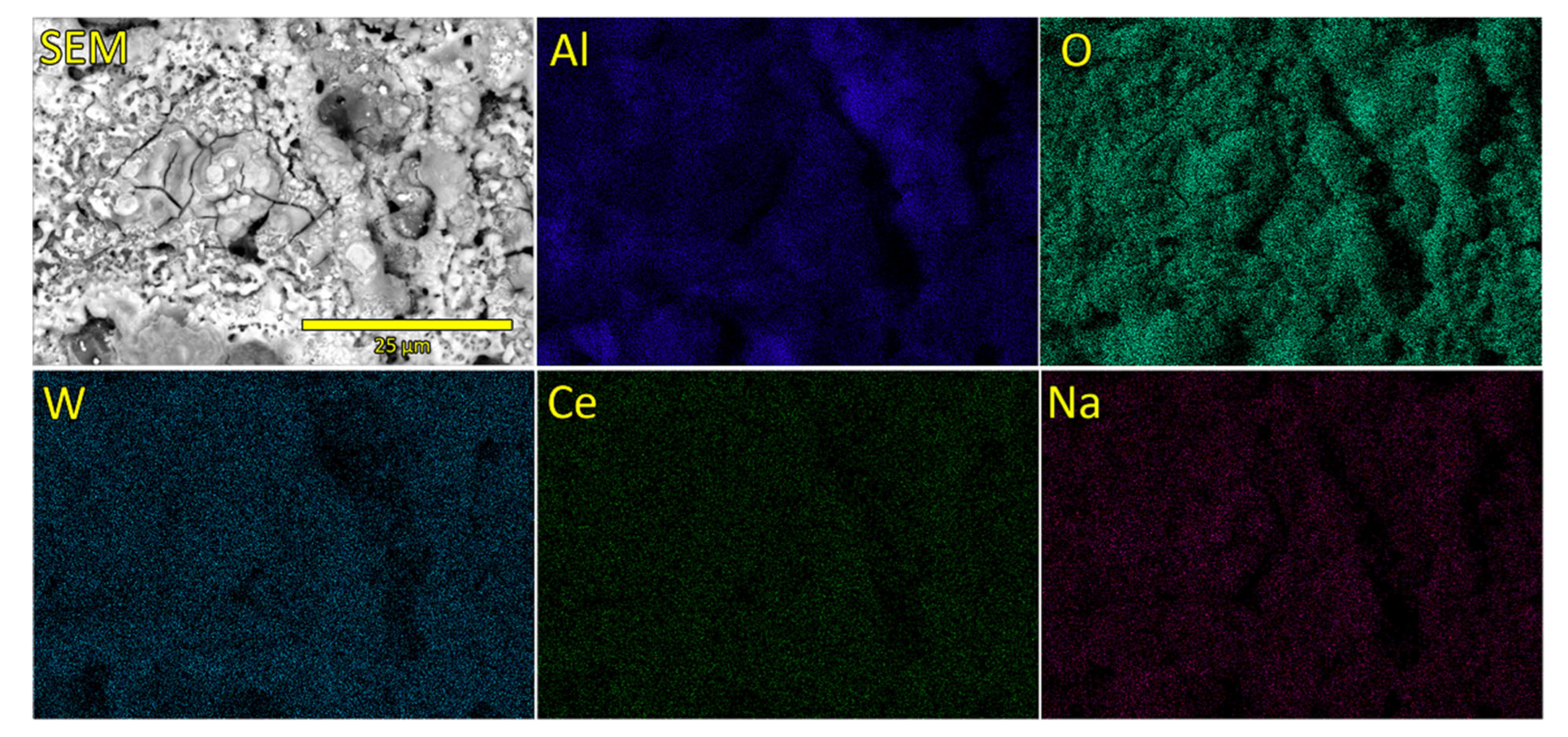
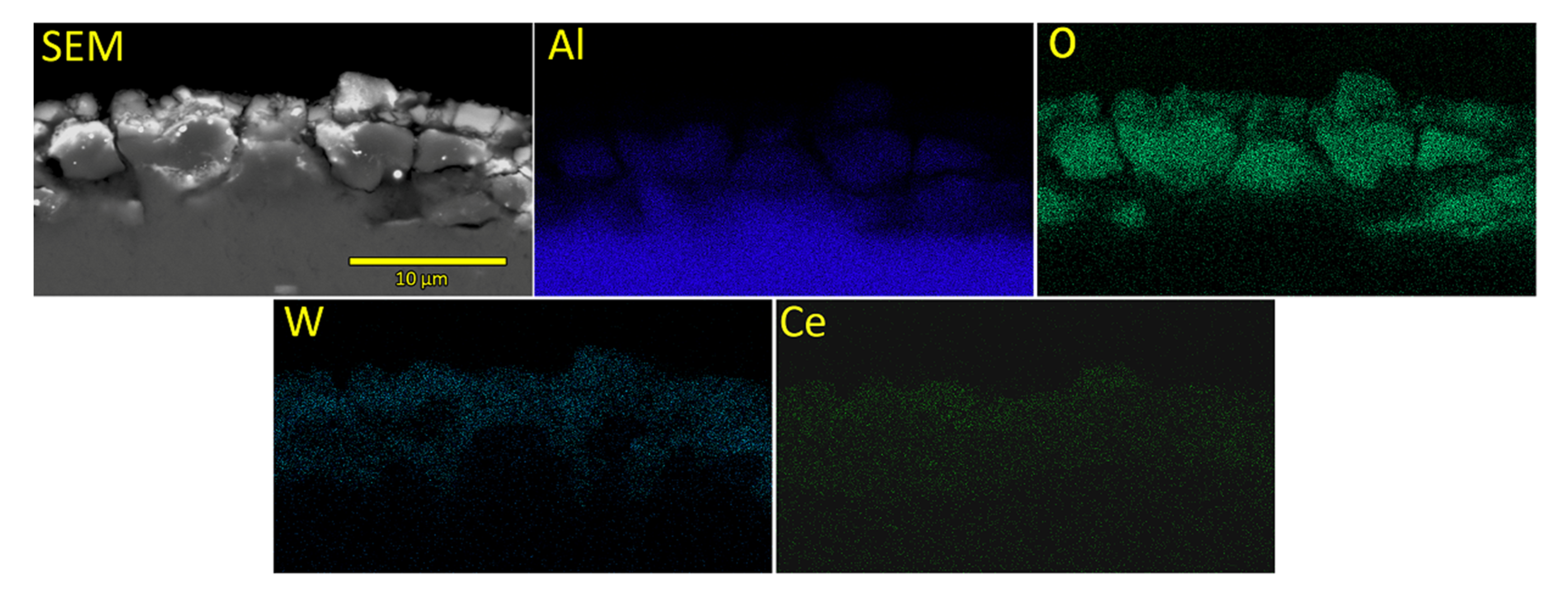
3.1. Morphology, Chemical and Phase Composition of Formed PEO Coatings

XRD patterns of oxide coatings prepared in all electrolyte solutions after 10 min of PEO processing are presented in Figure 2a. Powder XRD patterns of pure 13X zeolite and CeO2 are also presented in Figure 2a for comparison. As one can see from Figure 2, characteristic reflections of zeolite and CeO2 powder are not visible in XRD patterns of prepared oxide coatings, most probably as a result of their low concentration or good dispersion. Alongside, previously published articles which were focused on the incorporation of either zeolites or CeO2 into PEO coatings did not observe the reflections corresponding to these additives even up to concentrations of 10 g/L and 4 g/L, respectively [23,25]. For all prepared coatings only pronounced XRD maxima originating from Al substrate (COD 1512488) and low maxima originating from γ-Al2O3 (COD 1010461) denoted as Al and γ, respectively, are detected. Aside from these maxima, on high-resolution scan (Figure 2b), one can also observe a series of small maxima in the range from 23 to 25 degrees, which may be attributed to reflections corresponding to WO3 (COD 1010618) and non-stoichiometric phase W3O8 (COD 2101050) [26]. Observed reflections can be attributed to d001 = 3.820 Å, d020 = 3.740 Å, and d200 = 3.640 Å interplanar spacing in WO3, while W3O8 reflection corresponds to d001 = 3.774 Å.
Figure 3 shows top-view SEM micrographs of coatings created during a 10 min PEO process. Surface morphology of all PEO coatings prepared in this study is similar to each other. Most notable differences between the micrographs presented in Figure 3 are related to the presence of cracks in coatings with lower concentration of particles in electrolyte solution (Figure 3a,b) and appearance of nodules on coatings with the higher concentration of particles in electrolyte (Figure 3c–e). Appearance of cracked coatings is inherent to PEO processing, especially when prepared coatings are thin [11]. Conversely, the appearance of nodules may be related to increased concentration of particles and inert incorporation of particles on top of the formed coatings [12]. To further analyze the surfaces of prepared PEO coatings a set of EDS analyses is conducted (Table 2).
Data presented in Table 2 are averaged results over three EDS analyses on different areas of prepared coatings. One can see that elements detected in all coatings are either coming from the substrate or from the electrolyte. However, one must be very careful when evaluating EDS data because a large experimental error (up to 7 wt%) can be associated with the measurement data (when standard deviation of EDS measurements is taken into account). It is interesting to observe that Ce is detected only in the case when 1 g/L of CeO2 powder is added to electrolyte solution, and even this concentration is very low, i.e., it nears the detection limit of the EDS system used in this study. Another interesting result that can be extracted is the presence of Si in the coatings which exclusively originates from the zeolite powder in the solution, suggesting that zeolites are incorporated into prepared PEO coatings.
EDS mapping of elements detected on the surface of SEZC3 sample is presented in Figure 4. While the content and distribution of Al, O and W are well visible and can be related to the growth mechanism of PEO coatings, Na and Ce distributions are barely visible. This suggests that their concentrations are very low (as can be deduced from Table 2). However, from elemental maps it can be observed that those two elements are well dispersed over the surface, except in the microdischarging channels, proposing that these are most likely trapped into oxide coatings when molten material which is ejected out of the microdischarge channels and cools down in contact with electrolyte solution [10].
Top-view SEM images served as a source for extraction of important parameters such as surface roughness and porosity, which undoubtedly influence the photocatalytic properties of formed oxide coatings (Table 3). Values reported in Table 3 are average values for five different surface areas obtained using SEM. Evidently, average surface roughness increases with the concentration of particle additions to electrolyte solution, while the porosity decreases. This trend is also observed in our previous study [26] and it strongly influences the photocatalytic properties of formed coatings, as will be discussed in detail later.
Further inspection of formed PEO coatings was done by embedding samples in epoxy resin and cross-sectional polishing in order to extract more information regarding the coating thickness and elemental composition profile. Cross-sectional SEM images are presented in Figure 5. Gradual thickening of formed coatings is observed. The thickening starts from the thinnest coatings obtained in sodium tungstate electrolyte solution. The thickest coating is formed in the electrolyte SEZC3 which was processed in the electrolyte solution with the highest concentration of particles. In order to quantify thickening, precise thickness measurements were performed on five different locations in prepared cross-sections and average values are reported in the last column of Table 3. Thickening of formed PEO coatings with increased concentration of particles in electrolyte solution can be related to the fact that both zeolite 13X and CeO2 particles have negative zeta potential at pH of electrolyte used for PEO processing [27,28]. Namely, potential applied between the electrodes drives negatively charged particles toward anode surface during PEO processing. Locally high temperatures inherent to microdischarging and subsequent rapid cooling of molten oxide in contact with electrolyte entrap these particles inside oxide coatings making them thicker and denser [12,13]. It can also be observed that coatings denoted as SE and SEZ are more porous and less dense than the remaining coatings with addition of CeO2 particles. This is in agreement with results from literature showing that PEO coatings formed in electrolyte solutions that contain particles are denser and thicker than the coatings which are formed in electrolytes without the addition of particles [13,14,29].
EDS mapping of cross-section corresponding to the sample SEZC3 is presented in Figure 6. Utilized EDS attachment was not able to quantify the concentration of Ce detected in the cross-section, but Ce EDS map is shown in Figure 6 demonstrating that Ce is detected, but its concentration is below the detection limit of the system. All other detected elements, except Al, are evenly distributed through the formed PEO coating, while Al concentration is somewhat higher closer to the substrate.

3.2. Photoluminescent and Photocatalytic Properties of Formed PEO Coatings

Previously shown characterizations of PEO coatings formed in sodium tungstate electrolyte solution with the addition of 13X zeolite and different concentration of CeO2 were not able to undoubtedly demonstrate the presence of cerium-containing species in the coatings. Since photoluminescence (PL) is a sensitive optical technique capable to identify small quantity of optically active species on the surface of the samples, a set of emission PL measurements is conducted. Prepared PEO coatings were subjected to irradiation with 285 nm excitation wavelength and emission spectra were recorded (Figure 7). Oxide coating formed by PEO processing in sodium tungstate electrolyte as well as the coating formed with the addition of 13X zeolite to this electrolyte feature rather smooth emission PL spectra without clearly pronounced emission maxima. In contrast to this, all oxide coatings formed in electrolyte that contains CeO2 powder showed well pronounced emission PL maxima at approximately 330 nm, which correspond to Ce3+ emission [25]. It is worth noting that the initial oxidation state of ceria powder used in this study as an additive to electrolyte solution is Ce4+, but it is well documented that during the PEO processing Ce4+ changes its oxidation state to Ce3+ (for example, see Figure 3 in Ref. [25]).
Photocatalytic activity of PEO coatings formed in this study is shown in Figure 8a. while Figure 8b presents the results of MO adsorption in the dark in the presence of prepared photocatalytic oxide coatings. In Figure 8a,b C0 denotes the initial concentration of MO, while C denotes the concentration of MO after time t. It can be observed that photocatalytic activity of PEO coatings increases with the addition of zeolite to supporting electrolyte and it is further enhanced with addition of CeO2 powder. The highest photocatalytic activity reaches 50% and it is achieved with photocatalytic oxide coating processed in electrolyte solution containing 1 g/L of 13X zeolite and 1 g/L of CeO2. Adsorption of MO in the presence of photocatalytic coatings and absence of light (Figure 8b) is below 10% so it can be assumed that results presented in Figure 8a are related only to photocatalytic decomposition of MO in the presence of photocatalytic oxide coatings.
Upon irradiation the photocatalyst generates electron–hole pairs, initiating key reactions essential for efficient degradation of methyl orange. For optimal degradation, it is crucial to inhibit the recombination of formed electron–hole pairs, as recombination limits the availability of reactive species. In this process photogenerated electrons migrate from the valence band to the conduction band leaving behind positively charged holes in the valence band.
Generated conduction band electrons can readily interact with molecular oxygen (O2), producing the superoxide anion radical (O2•−). This anion reacts further, ultimately leading to the formation of hydrogen peroxide (H2O2). Subsequently, H2O2 decomposes to generate hydroxyl radicals (OH), known for their high reactivity. Meanwhile, the remaining holes in the valence band can react directly with water molecules, generating additional OH radicals.
The oxidative degradation of azo dyes, such as methyl orange, is predominantly driven by repeated interactions with these highly reactive OH radicals, which break down the dye’s molecular structure through successive oxidation steps [30].

4. Discussion

The main goal of presented research was to identify whether it is possible to perform facile co-deposition of zeolite 13X and CeO2 using PEO processing to form photocatalytically active oxide coatings. In our previous work [26] Ce-loaded 13X zeolite was incorporated into PEO coatings using continuous DC PEO in sodium tungstate-based electrolyte, where cerium containing form of 13X zeolite was obtained using conventional aqueous ion exchange procedure [17]. This is a common procedure and it has been used by many authors [21,23] in order to load various types of zeolites with Ce ions. However, this procedure requires long preparation time and it may be possible to make this process more time efficient by adding CeO2 directly into the electrolyte solution and to perform a co-deposition of CeO2 and zeolite. Ce atoms in CeO2 are in Ce4+ oxidation state and it is well known that CeO2 can accept or release O2 where Ce changes its oxidation state from Ce3+ to Ce4+ or from Ce4+ to Ce3+ following the equation [31]:
2 C e O 2 2 C e O 2 x + x O 2   ( 0 x 1 )
In the case of PEO processed oxide coatings, a large number of oxygen vacancy defects is formed in coatings and Ce oxidation state is readily reduced to Ce3+ due to the existence of locally high temperatures inside of microdischarging channels [25,32]. The addition of CeO2 to electrolyte was calculated in such a way that it covers the concentration of Ce in Ce-loaded 13X zeolite (25.5 ± 1.3 wt%) realized in our previous work [14]. Results obtained in this study showed that even with concentration as high as 1 g/L of CeO2 in electrolyte solution, CeO2 diffraction maxima were not present in XRD patterns, while the concentration of Ce on the surfaces of prepared PEO coatings was close to (or below) the limit of detection of EDS system. Furthermore, as in the case of incorporation of Ce-loaded zeolites, morphological characteristics followed similar trends, i.e., surface roughness increased, while porosity decreased with increased incorporation species coming from the electrolyte. Increased concentration of CeO2 in electrolyte results in increased roughness. Consequently, specific surface area increases, i.e., more photoactive centers are available and overall photoactivity increases.
PL emission spectra for all coatings formed in electrolyte with CeO2 addition feature maxima characteristic for Ce3+ ion luminescence. This result suggests that due to a large number of oxygen vacancy defects and under locally high temperatures Ce4+ reduces to Ce3+, revealing that PEO processing may be also used for Ce4+/Ce3+ redox-controlled luminescence [33,34].
Photodecomposition of MO under simulated sunlight irradiation in the presence of prepared oxide coatings (Figure 8a) clearly demonstrates that addition of zeolite 13X to the sodium tungstate electrolyte solution increases photoactivity. Subsequent addition of CeO2 in different concentrations also favors this increase, which can be related to changes in surface morphology of the samples. Namely, increased surface roughness is closely related to an increase of surface area available for photodecomposition of MO, which is favorable for photocatalytic activity. On the other hand, porosity decreases with increasing addition of particles to electrolyte solution, suggesting that tortuosity of microdischarge channels, i.e., pores, is rather high and prevents light as an immaterial agent to enter deep into microdischarge channels where it can trigger the photodecomposition of MO.
Figure 8a also reveals the contribution of increased CeO2 concentration in electrolyte to the photocatalytic activity of formed coatings: higher concentration of CeO2 in electrolyte solution results in higher photoactivity. This may lead to a speculation that Ce3+ ions incorporated into Al2O3 matrix which emit strong PL in the near ultraviolet region (Figure 7) act as secondary source of irradiation thus increasing irradiation intensity and enhancing photodecomposition of MO. Since the lamp that was used for irradiation covers UV part of the solar spectrum it can be expected that it serves as an excitation source for Ce3+ ions, which emit radiation that can participate in photocatalytic reactions [35].

5. Conclusions

Oxide coatings with co-deposited 13X zeolite and CeO2 are formed using PEO processing for 10 min in 0.01 M Na2WO4 water-based solutions. The main goal of this study was to investigate whether it is possible to use simple co-deposition of above mentioned species to obtain photocatalysts that are comparable to those made with the incorporation of Ce-loaded zeolite 13X in the same electrolyte. Based on experimental data, the following conclusions can be drawn:
  • It is possible to form photoactive PEO coatings via co-deposition of 13X zeolite (1 g/L) and varying concentration of CeO2 (0.25 g/L, 0.5 g/L, and 1 g/L). Roughness of obtained coatings increases with the addition of 13X zeolite and CeO2 to solution, while their porosity decreases.
  • Chemical composition of formed oxide coatings reveals the presence of species originating both from the substrate and from the electrolyte solution. Although Ce can be detected in oxide coatings, its concentration is near or below the detection limit of used EDS system.
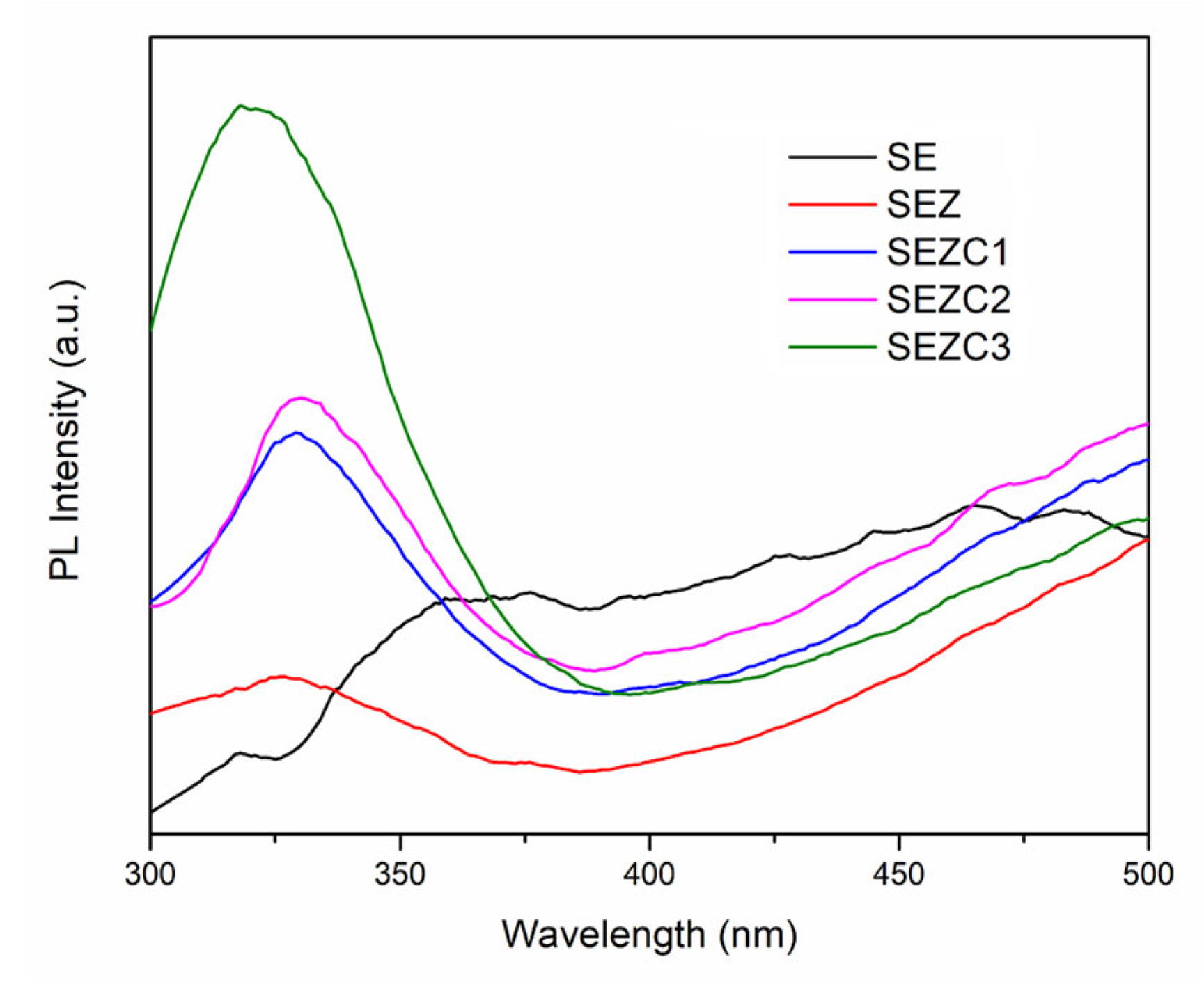
  • Semiquantitative detection of Ce is performed utilizing photoluminescence. PL emission spectra of coatings formed with addition of CeO2 to electrolyte feature luminescent peak corresponding to Ce3+. The concentration of Ce (observed as intensity of emission PL peak corresponding to Ce3+) increases with increased addition of CeO2 to electrolyte solution.
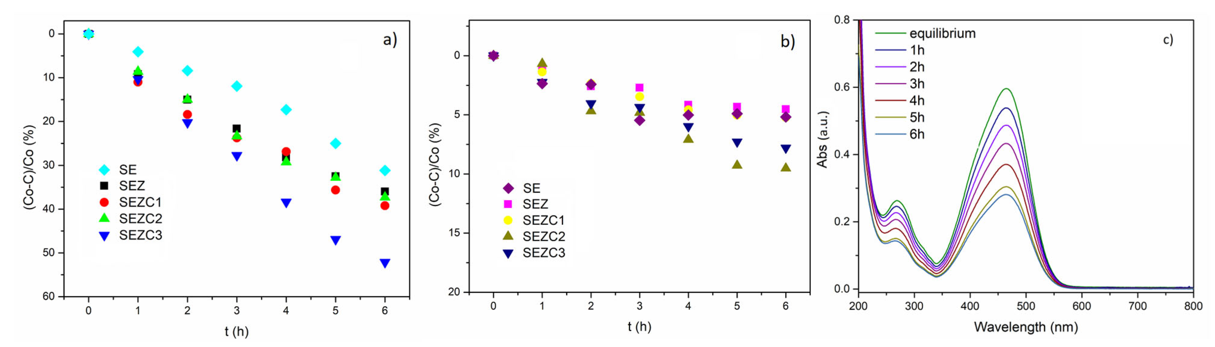
  • Photodecomposition of MO registered for SEZC3 sample is found to be 50% of initial Mo concentration, which is comparable to photodecomposition value of 60% observed for oxide coatings with incorporated Ce-loaded 13X zeolite processed for 10 min under the same PEO conditions. However, the sample SEZC1 with chemical composition similar to chemical composition of PEO coatings with incorporated Ce-loaded 13X zeolite has photocatalytic activity which is 1.5 times lower.
  • Although co-deposition of 13X zeolite and CeO2 is a viable method for producing photocatalytic coatings, it requires higher concentration of CeO2 in electrolyte to achieve similar values of photocatalytic decomposition as in the case of PEO incorporation of Ce-loaded zeolites.

Author Contributions

Conceptualization, R.V. and K.M.; methodology, K.M. and N.T.; investigation, K.M., N.T. and S.S.; data curation, K.M., N.T. and S.S.; writing—original draft preparation, R.V. and L.D.-V.; writing—review and editing, R.V., L.D.-V. and K.M.; visualization, K.M.; supervision, R.V. and L.D.-V.; project administration, R.V.; funding acquisition, R.V. All authors have read and agreed to the published version of the manuscript.

Funding

This research was funded by the Science Fund of the Republic of Serbia, grant number 7309 ZEOCOAT, the European Union Horizon 2020 research and innovation program under the Marie Sklodowska-Curie grant agreement No. 823942 (FUNCOAT), and the Ministry of Science, Innovation, and Technological Development of the Republic of Serbia (451-03-65/2024-03/200162 and 451-03-65/2024-03/200146).

Institutional Review Board Statement

Not applicable.

Informed Consent Statement

Not applicable.

Data Availability Statement

Data is contained within the article.

Conflicts of Interest

The authors declare that they have no known competing financial interests or personal relationships that could have appeared to influence the results reported in this paper.

References

  1. Silva, J.A. Wastewater treatment and reuse for sustainable water resources management: A systematic literature review. Sustainability 2023, 15, 10940. [Google Scholar] [CrossRef]
  2. Zhang, L.; Xiong, Z.; Li, L.; Burt, R.; Zhao, X.S. Uptake and degradation of Orange 2 by zinc aluminum layered double oxides. J. Colloid Interface Sci. 2016, 469, 224–230. [Google Scholar] [CrossRef] [PubMed]
  3. Zhao, Q.; Wen, W.; Xia, Y.; Wu, J.M. Photocatalytic activity of TiO2 nanorods, nanowires and nanoflowers filled with TiO2 nanoparticles. Thin Solid Film. 2018, 648, 103–107. [Google Scholar] [CrossRef]
  4. Koe, W.S.; Lee, J.W.; Chong, W.C.; Pang, Y.L.; Sim, L.C. An overview of photocatalytic degradation: Photocatalysts, mechanisms, and development of photocatalytic membrane. Environ. Sci. Pollut. Res. 2020, 27, 2522–2565. [Google Scholar] [CrossRef] [PubMed]
  5. Pavel, M.; Anastasescu, C.; State, R.-N.; Vasile, A.; Papa, F.; Balint, I. Photocatalytic degradation of organic and inorganic pollutants to harmless end products: Assessment of practical application potential for water and air cleaning. Catalysts 2023, 13, 380. [Google Scholar] [CrossRef]
  6. Reddy, B.M.; Reddy, E.P.; Mehdi, S. Phase transformation study of titania in V2O5TiO2 and MoO3TiO2 catalysts by X-ray diffraction analysis. Mat. Chem. Phys. 1994, 36, 276–281. [Google Scholar] [CrossRef]
  7. Seyed Dorraji, M.S.; Rasoulifard, M.H.; Daneshvar, H.; Vafa, A.; Amani-Ghadim, A.R. ZnS/ZnNiAl-LDH/GO nanocomposite as a visible-light photocatalyst: Preparation, characterization and modeling. J. Mater. Sci. Mater. Electron. 2019, 30, 12152–12162. [Google Scholar] [CrossRef]
  8. Lee, D.-E.; Kim, M.-K.; Danish, M.; Jo, W.-K. State-of-the-art review on photocatalysis for efficient wastewater treatment: Attractive approach in photocatalyst design and parameters affecting the photocatalytic degradation. Catal. Commun. 2023, 183, 106764. [Google Scholar] [CrossRef]
  9. Pansila, P.P.; Witit-Anun, N.; Chaiyakun, S. Effect of oxygen partial pressure on the morphological properties and the photocatalytic activities of titania thin films on unheated substrates by sputtering deposition method. Adv. Mater. Res. 2013, 770, 18–21. [Google Scholar] [CrossRef]
  10. Yerokhin, A.L.; Nie, X.; Matthews, A.; Dowey, S.J. Plasma electrolysis for surface engineering. Surf. Coat. Technol. 1999, 122, 73–93. [Google Scholar] [CrossRef]
  11. Kaseem, M.; Fatimah, S.; Nashrah, N.; Ko, Y.G. Recent progress in surface modification of metals coated by plasma electrolytic oxidation: Principle, structure, and performance. Prog. Mater. Sci. 2021, 117, 100735. [Google Scholar] [CrossRef]
  12. Lu, X.; Mohedano, M.; Blawert, C.; Matykina, E.; Arrabal, R.; Kainer, K.U.; Zheludkevich, M.L. Plasma electrolytic oxidation coatings with particle additions—A review. Surf. Coat. Technol. 2016, 307, 1165–1182. [Google Scholar] [CrossRef]
  13. Lu, X.; Blawert, C.; Zheludkevich, M.L.; Kainer, K.U. Insights into plasma electrolytic oxidation treatment with particle addition. Corros. Sci. 2015, 101, 201–207. [Google Scholar] [CrossRef]
  14. Mojsilović, K.; Božović, N.; Stojanović, S.; Damjanović-Vasilić, L.; Serdechnova, M.; Blawert, C.; Zheludkevich, M.L.; Stojadinović, S.; Vasilić, R. Zeolite-containing photocatalysts immobilized on aluminum support by plasma electrolytic oxidation. Surf. Interfaces 2021, 26, 101307. [Google Scholar] [CrossRef]
  15. Zhang, Y.; Wang, J.; Zhao, S.; Serdechnova, M.; Blawert, C.; Wang, H.; Zheludkevich, M.L.; Chen, F. Double-ligand strategy to construct an inhibitor-loaded Zn-MOF and its corrosion protection ability for aluminum alloy 2A12. ACS Appl. Mater. Interfaces 2021, 13, 51685–51694. [Google Scholar] [CrossRef] [PubMed]
  16. Wei, K.; Zhao, X.; Zhang, Z.; Yuan, Y.; Kong, W.; Zhang, Y. Duplex coating combining vanadate-intercalated layered double hydroxide and Ce-doped sol-gel layers on aluminum alloy for active corrosion protection. Materials 2023, 16, 775. [Google Scholar] [CrossRef] [PubMed]
  17. Dondur, V.; Dimitrijević, R.; Kremenović, A.; Damjanović, L.; Kićanović, M.; Cheong, H.M.; Macura, S. Phase transformations of hexacelsians doped with Li, Na and Ca. Mater. Sci. Forum 2005, 494, 107–112. [Google Scholar] [CrossRef]
  18. Galvão, T.L.P.; Bouali, A.C.; Serdechnova, M.; Yasakau, K.A.; Zheludkevich, M.L.; Tedim, J. Chapter 16—Anticorrosion thin film smart coatings for aluminum alloys. In Advances in Smart Coatings and Thin Films for Future Industrial and Biomedical Engineering Applications; Makhlouf, A.S.H., Abu-Thabit, N.Y., Eds.; Elsevier: Amsterdam, The Netherlands, 2020; pp. 429–454. [Google Scholar]
  19. Alvarez-Aguiñaga, E.A.; Elizade-Gonzalez, M.; Sabinas-Hernandez, S.A. Unpredicted photocatalytic activity of clinoptilolite-mordenite natural zeolite. RSC Adv. 2020, 10, 39251–39260. [Google Scholar] [CrossRef]
  20. Latha, P.; Karuthapandian, S. Novel, facile and swift technique for synthesis of CeO2 nanocubes immobilized on zeolite for removal of CR and MO dye. J. Clust. Sci. 2017, 28, 3265–3280. [Google Scholar] [CrossRef]
  21. Chen, Q.; Lu, X.; Serdechnova, M.; Wang, C.; Lamaka, S.; Blawert, C.; Zheludkevich, M.L.; Wang, F. Formation of self-healing PEO coatings on AM50 Mg by in-situ incorporation of zeolite micro-container. Corros. Sci. 2022, 209, 110785. [Google Scholar] [CrossRef]
  22. Mojsilović, K.; Božović, N.; Stojanović, S.; Damjanović-Vasilić, L.J.; Serdechnova, M.; Blawert, C.; Zheludkevich, M.L.; Stojadinović, S.; Vasilić, R. Oxide coatings with immobilized Ce-ZSM5 as visible light photocatalysts. J. Serb. Chem. Soc. 2022, 87, 1035–1048. [Google Scholar]
  23. Al Abri, S.; Rogov, A.; Aliasghari, S.; Bendo, A.; Matthews, A.; Yerokhin, A.; Mingo, B. In-situ incorporation of Ce-zeolite during soft sparking plasma electrolytic oxidation. J. Mater. Res. Technol. 2024, 30, 2365–2376. [Google Scholar] [CrossRef]
  24. Clyne, T.W.; Troughton, S.C. A review of recent work on discharge characteristics during plasma electrolytic oxidation of various metals. Int. Mater. Rev. 2019, 64, 127–162. [Google Scholar] [CrossRef]
  25. Stojadinović, S.; Vasilić, R. Photoluminescence of Ce3+ and Ce3+/Tb3+ ions in Al2O3 host formed by plasma electrolytic oxidation. J. Lumin. 2018, 203, 576–581. [Google Scholar] [CrossRef]
  26. Mojsilović, K.; Lačnjevac, U.; Stojanović, S.; Damjanović-Vasilić, L.J.; Stojadinović, S.; Vasilić, R. Formation and properties of oxide coatings with immobilized zeolites obtained by plasma electrolytic oxidation of aluminum. Metals 2021, 11, 1241. [Google Scholar] [CrossRef]
  27. Akhtar, F.; Bergstro, L. Colloidal Processing and Thermal Treatment of Binderless Hierarchically Porous Zeolite 13X Monoliths for CO2 Capture. J. Am. Ceram. Soc. 2011, 94, 92–98. [Google Scholar] [CrossRef]
  28. Kosmulski, M. The pH dependent surface charging and points of zero charge. X. Update. Adv. Colloid Interface Sci. 2023, 319, 102973. [Google Scholar] [CrossRef] [PubMed]
  29. Arrabal, R.; Mohedano, M.; Matykina, E.; Pardo, A.; Mingo, B.; Merino, M.C. Characterization and wear beahviour of PEO coatings on 6082-T6 aluminium alloy with incorporated α-Al2O3 particles. Surf. Coat. Technol. 2015, 269, 64–73. [Google Scholar] [CrossRef]
  30. Latha, P.; Prakash, K.; Karuthapandian, S. Enhanced visible light photocatalytic activity of CeO2/alumina nanocomposite: Synthesized via facile mixing-calcination method for dye degradation. Adv. Powder Technol. 2017, 28, 2903–2913. [Google Scholar] [CrossRef]
  31. Sridharan, M.; Maiyalagan, T. Synergistically enhanced electrocatalytic activity of cerium oxide/manganese tungstate composite for oxygen reduction reaction. J. Mater. Sci. Mater. Electron. 2022, 33, 9538–9548. [Google Scholar] [CrossRef]
  32. Manojkumar, P.; Lokeshkumar, E.; Premchand, C.; Saikiran, A.; Rama Krishna, L.; Rameshbabu, N. Facile preparation of immobilized visible light active W-TiO2/rGO composite photocatalyst by plasma electrolytic oxidation process. Phys. B Condens. Matter 2022, 632, 413680. [Google Scholar] [CrossRef]
  33. Kim, H.; Kim, M.; Byeon, S.-H. Ce4+/Ce3+ redox-controlled luminescence ‘on/off’ switching of highly oriented Ce(OH)2Cl and Tb-doped Ce(OH)2 Cl films. J. Mater. Chem. C 2017, 5, 444–451. [Google Scholar] [CrossRef]
  34. Berwal, U.; Singh, V.; Sharma, R. Effect of Ce4+→Ce3+ conversion on the structural and luminescence properties of Ce4+ doped Gd2Ti2O7 pyrochlore oxide. J. Lumin. 2023, 257, 119687. [Google Scholar] [CrossRef]
  35. Stojadinović, S.; Radić, N.; Tadić, N.; Vasilić, R.; Grbić, B. Enhanced ultraviolet light driven photocatalytic activity of ZnO particles incorporated by plasma electrolytic oxidation into Al2O3 coatings co-doped with Ce. Opt. Mater. 2020, 101, 109768. [Google Scholar] [CrossRef]
Figure 1. The evolution of the anodization voltage during the PEO processing.
Coatings 14 01516 g001
Figure 2. XRD patterns of oxide coatings formed by PEO processing for 10 min: (a) survey scan; (b) high-resolution scan in the range of interest.
Coatings 14 01516 g002
Figure 3. Top surface morphology of coatings obtained during 10 min PEO processing in: (a) SE; (b) SEZ; (c) SEZC1; (d) SEZC2; (e) SEZC3.
Coatings 14 01516 g003
Figure 4. EDS mapping of PEO surface formed in SEZC3.
Coatings 14 01516 g004
Figure 5. Cross-sectional SEM images of coatings obtained after 10 min of PEO processing in: (a) SE; (b) SEZ; (c) SEZC1; (d) SEZC2; (e) SEZC3.
Coatings 14 01516 g005
Figure 6. EDX mapping of SEZC3 coating cross-section.
Coatings 14 01516 g006
Figure 7. Emission PL spectra of PEO coatings under 285 nm excitation.
Coatings 14 01516 g007
Figure 8. (a) Photodecomposition of MO after 6 h of irradiation with simulated sunlight; (b) absorption of MO in the dark; (c) MO degradation absorbance spectra for SEZC3 sample.
Coatings 14 01516 g008
Table 1. Sample designation and electrolyte used for PEO processing.
Sample NameElectrolytepHConductivity (mS)
SE0.01 M Na2WO4∙2H2O7.302.04
SEZSE + 1 g/L 13X7.052.08
SEZC1SE + 1 g/L 13X + 0.25 g/L CeO27.042.07
SEZC2SE + 1 g/L 13X + 0.5 g/L CeO27.052.08
SEZC3SE + 1 g/L 13X + 1 g/L CeO27.062.07
Table 2. Elemental composition of PEO coatings presented in Figure 3.
Sample NameComposition (wt%)
ONaAlWSiCe
SE32.240.6124.5738.653.93-
SEZ32.340.5117.8545.194.11-
SEZC135.850.3519.3640.434.01-
SEZC230.650.5619.4746.083.24-
SEZC331.330.3219.5247.730.940.16
Table 3. Roughness, porosity and thickness of formed PEO coatings.
SampleRoughness (μm)Porosity (%)Thickness (µm)
SE1.4511.452.7
SEZ1.9110.754.1
SEZC11.948.296.2
SEZC21.957.347.3
SEZC31.977.157.4
Disclaimer/Publisher’s Note: The statements, opinions and data contained in all publications are solely those of the individual author(s) and contributor(s) and not of MDPI and/or the editor(s). MDPI and/or the editor(s) disclaim responsibility for any injury to people or property resulting from any ideas, methods, instructions or products referred to in the content.

