Article

Nonlinear Oxidation Behavior at Interfaces in Coated Steam Dual-Pipe with Initial Waviness and Cooling Temperature

1
School of Mechanical Engineering, Inner Mongolia University of Science and Technology, Baotou 014010, China
2
Chinese Aeronautical Establishment, Beijing 100029, China
3
School of Aeronautic Science and Engineering, Beihang University, Beijing 100191, China
*
Authors to whom correspondence should be addressed.
Coatings 2024, 14(12), 1478; https://doi.org/10.3390/coatings14121478
Submission received: 24 September 2024 / Revised: 17 November 2024 / Accepted: 20 November 2024 / Published: 22 November 2024
(This article belongs to the Section Ceramic Coatings and Engineering Technology)

Abstract

:
A numerical simulation method is proposed to investigate the nonlinear growth of thermally grown oxide (TGO) on a novel coated steam dual-pipe system operating at 700 °C. Utilizing oxidation kinetics data from high-temperature water vapor experiments, the study examines interface stresses and morphology evolution, considering initial surface waviness and cooling temperature effects. The findings indicate that the parabolic law accurately describes the nonlinear growth of TGO during high-temperature water vapor oxidation, with the TGO growth oxidation rate constant being 4.5 × 10 4 μ m 2 / h . The growth rate of TGO thickness decreases with increasing oxidation duration. Stress concentrations are found to develop at TGO interfaces, particularly in regions with high curvature, and those with elevated wavy amplitudes. The primary factor influencing stress redistribution and morphology evolution is the wavy amplitude of the TGO. Additionally, variations in cooling temperature affect interface stresses along the axial direction of the pipe system during nonlinear oxidation, resulting in relatively minor changes in morphology.

1. Introduction

In recent years, advanced ultra-supercritical coal (USC) technology, known for its high efficiency and low emissions, has arisen as a crucial strategy for achieving global energy-saving and emission reduction goals [1]. However, the primary technical challenge limiting the design and construction of USC power stations operating at 630–700 °C remains the development of heat-resistant materials. To address the requirements for heat insulation and oxidation resistance in the main steam pipe of ultra-supercritical units, an innovative coated dual-pipe system utilizing thermal barrier coatings (TBCs) has been proposed [2]. This system, illustrated in Figure 1 [3,4], comprises four material layers: a ceramic topcoat (TC), a bonding coat (BC), a P92 steel substrate (SUB), and a thermally grown oxide (TGO) layer primarily composed of alumina formed between the ceramic and bonding layers. The complex, multilayered structure of the coating system makes it susceptible to failure over prolonged operation. Common failure modes include debonding between the TC and BC layers, cracking of the TC layer, and the penetration of cracks through multiple layers [5,6]. Among these, the thermal growth and stress evolution of the TGO layer are usually regarded as the primary factors contributing to crack formation and spalling failures within the TBC system [7,8,9].
To investigate the thermal growth mechanism of TGO during service, extensive experimental studies have been conducted worldwide. These studies [10,11,12,13] reveal that the evolution of TGO thickness over time comprises distinct stages: an initial rapid oxidation phase primarily driven by the TC/BC interface reaction, a subsequent stable oxidation phase governed by oxygen diffusion, and a complex oxidation phase where Al 2 O 3 reacts with metallic elements like Ni, Cr, and Co, forming a spinel structure. Due to differing mechanisms across stages, the growth thickness of TGO exhibits nonlinear characteristics. Building upon experimental data and growth mechanism analyses, the nonlinear growth of TGO has been approximated with the following function [14]:
h 2 = k t ,
where h represents the TGO thickness, t is the oxidation time, and k describes oxidation velocity. From a microstructural perspective, it is well known that the oxidation of high-temperature alloys often begins with the formation of a porous alumina layer, which gradually evolves into a denser structure over time. This transformation significantly affects the stress–strain relationship within the system, as the deformation—expressed as the integral of strain—occurs in tandem with changes in material properties such as Young’s modulus and Poisson’s ratio. This leads to nonuniform thickness variation in the TGO layer, especially during thermal cycling, which can be observed on a macrostructural level. Furthermore, this is a complex thermo-chemo-mechanical coupling phenomenon, where the evolution of TGO morphology and thickness is governed by factors such as temperature, stress, and the diffusion of elements.
Over the past two decades, extensive simulation research has been conducted on TGO growth due to the oxidation of TBC interfaces. The approaches can be broadly categorized into two types: mechanical-based simulations of TGO growth and those that incorporate the thermo-chemo-mechanical coupling mechanism to more closely reflect the procedure of oxidation. Freborg et al. [15] simulated TGO growth using finite element analysis with the element “birth” and “death” capabilities of NIKE, focusing on material property transformations but not capturing growth stresses induced by TGO oxidation. Addressing this limitation, Karlsson et al. [16,17] introduced a method applying stress-free strain to elements near the BC layer, enabling vertical TGO growth, together with the lateral strain across the TGO layer. Despite its widespread adoption, this approach is constrained in simulating thick TGO growth due to exaggerated single-layer expansion strains that compromise finite element accuracy. Subsequently, He et al. [18,19] simulated linear thickening of TGO by dividing layers with uniform transformation and growth strain in the BC layer, though it diverges from the nonlinear TGO growth observed in service conditions. From a macroscopic viewpoint, the nonlinear growth model proposed in this work builds upon the mechanical-based simulations.
This study proposes a novel simulation method for nonlinear TGO growth to analyze key factors influencing interfacial stress and morphology evolution in TBC systems. The experiments of high-temperature water vapor oxidation for TBCs are described first, followed by the numerical simulation strategies for the nonlinear growth of the TGO layer through material parameter transformation methods and growth strain imposition, combined with insights from Clarke et al. [20]. The corresponding UMAT subroutine on the ABAQUS platform is also presented for the analysis of how initial TGO morphology and cooling steam temperature impact stress distribution and morphology evolution at dual-pipe system interfaces. Results and discussion are presented. The concluding remarks and future research directions are given at the end of this work.

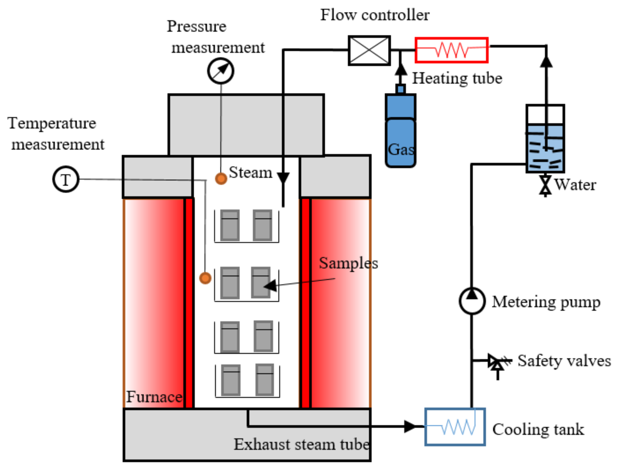
2. TBC High-Temperature Water Vapor Oxidation Experiments

The experiment utilized a commercial P92 heat-resistant steel as the substrate material in the TBC system, with the pipe sized at Φ390 × 70 mm, and Table 1 gives its chemical composition. The substrate was wirecut into strip specimens measuring 20 mm × 10 mm × 4 mm. Subsequently, atmospheric plasma spraying (APS) was employed to apply a ceramic layer using 8% yttrium oxide partially stabilized zirconium oxide ( ZrO 2 -8% Y 2 O 3 ) powder, branded as Metro 204NS by Oerlikon-Metco (Westbury, NY, USA). The APS technique was also used to generate a BC layer of NiCoCrAlY.
High-temperature oxidation experiments were conducted using the developed platform designed for water vapor corrosion in a high-temperature environment (see Figure 2 for a schematic). This platform is used for the study of the growth kinetics of TGO. During the experiment, specimens were heated to 700 °C and held at this temperature for varying durations: 25 h, 50 h, 100 h, 250 h, and 500 h. Subsequently, specimens were cooled down to 20 °C over 1 h using a temperature controller. The entire heating, holding, and cooling process was automated, ensuring deep oxidation between the TBC layers.

3. Simulation Strategy for the Nonlinear Growth of TGO Layer

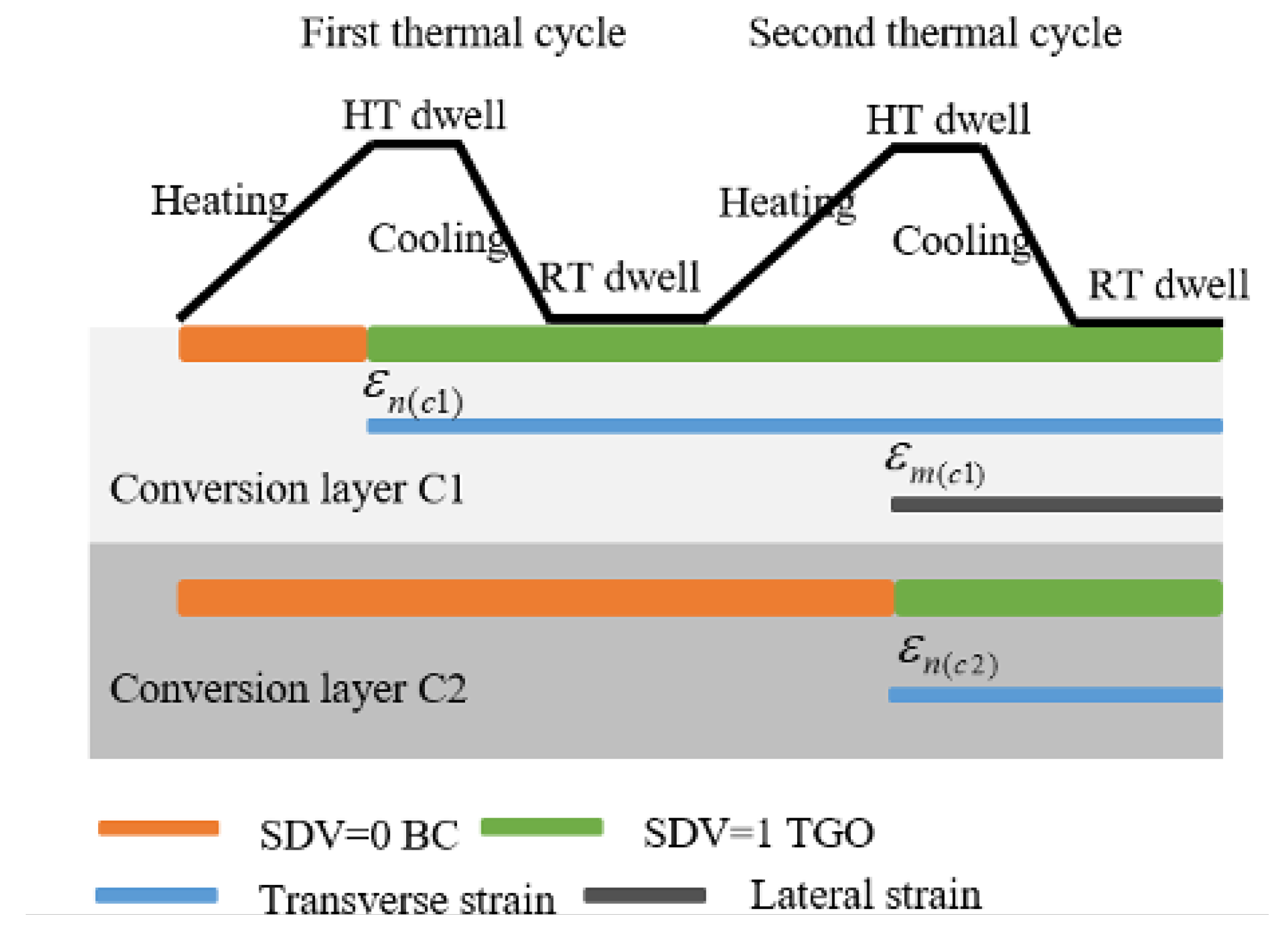
3.1. Material Parameter Transformation Method and Growth Strain Imposition

During the growth of the TGO layer, the volume of newly formed oxides exceeds that of the consumed material. The TGO layer meanwhile expands laterally along grain boundaries. These factors contribute to volumetric changes along its thickness and interface directions, leading to mismatched deformation between the TGO and BC layers. Consequently, growth stresses develop along the TGO interface in both the transverse and longitudinal directions. Karlsson et al. [16,17] proposed a model for the high-temperature ageing of TGO, giving its strain characteristics:
ε t o t = ε E + ε P + ε T + ε G ,
where ε t o t represents the total strain, ε E and ε P are elastic and plastic strains, respectively; ε T represents the thermal strain, and ε G represents the growth strain. Furthermore, the transverse strain rate employed here is related to the rate of thickness change in the TGO layer, that is,
ε ˙ m = h ˙ d ,
where ε ˙ m denotes the transverse strain rate, and h ˙ represents the thickness change rate of the TGO layer. In addition, the constant d takes the value of 0.03354 mm/ h 1 / 2 [20]. The ε m during transverse growth of the TGO is derived by combining Equations (1) and (3), giving
ε m = k t 2 d .
Furthermore, Rhines and Wolf et al. [21] observed that the volume of oxide growing along the TGO interface is relatively small compared to its growth in the thickness direction. This relationship is often described by a ratio in simulations. Following Su et al. [22], this study adopts a relationship that governs both transverse and longitudinal growth strains, as shown below:
ε m ε n = 0.5 .

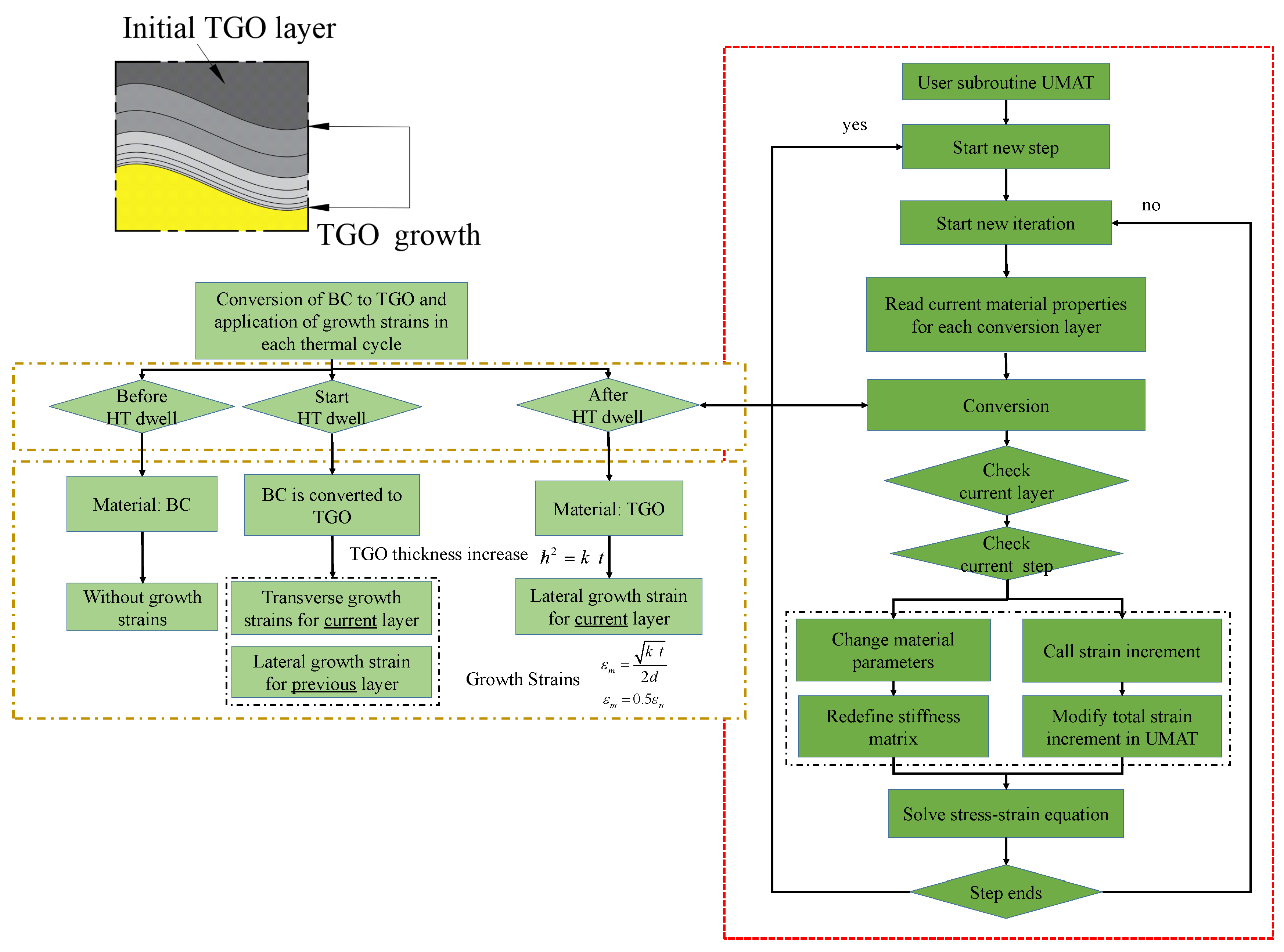
3.2. UMAT Development in ABAQUS for the Nonlinear Growth of TGO Layer

The materials transformation and growth of the TGO layer were implemented using the UMAT subroutine. Equation (1) enables calculation of the actual growth thickness of the TGO layer within each cycle comprised heating, high-temperature (HT) dwell, cooling, and room-temperature (RT) dwell. The BC layer was divided into transformation layers “CN” (where N = 1, 2, 3, …). For instance, C1 represents the TGO layer generated during the first thermal cycle. Next, material parameter transformation during cycling was managed through solution-dependent state variables (SDVs). These were initially set to 0, which indicates that the material properties correspond to the BC layer. A transition to 1 indicates complete transformation to TGO material properties. This transformation occurs over thermal cycles, with each stage affecting the state variables and thus the material properties of the transformed layers. Table 2 illustrates the variation in SDVs for transformation layers C1 and C2 across different stages of the initial two cycles. During Step 1, the heating phase of the first thermal cycle, the state variable for C1 transitions to 0, matching its material parameters with those of the BC layer. Subsequently, in Step 2, the HT dwell phase of the first thermal cycle, the state variable of C1 increases to 1, marking its transformation to TGO material parameters. In Step 3, during the cooling phase of the first cycle and subsequent RT dwell steps, the state variable remains at 1, indicating completion of the material transformation for that layer. Thus, the transition of material parameters from BC to TGO is realized for the first layer. The process for the transformation of material parameters for the second layer follows the same steps. Concurrently, during the phase of material parameter transformation in the RT dwell stage, assuming TGO growth strain as a function of TGO growth thickness, referenced in Equations (4) and (5), the UMAT subroutine applies lateral growth strain to both the initial TGO layer and the transformed layers undergoing current material parameter transformation, as well as thickness-direction growth strain. Figure 3 illustrates this process for the initial transformed layers.
Figure 4 illustrates the workflow of the UMAT subroutine used for simulating the nonlinear growth of the TGO layer. During execution, different layer materials are selected using pre-set variables. Subsequently, the program reads the current analysis step and determines whether it corresponds to the RT dwell stage. Based on this determination, the program either maintains the material properties of the transformation layer as BC layer without introducing growth strain increments before the corresponding RT dwell stage, or it gradually transitions the material properties from BC layer to TGO layer as it calculates up to the RT dwell stage. During this transition, longitudinal growth strain increments are applied. After reaching the RT dwell stage, the transformation layer’s material properties are those of the TGO layer, marking it as a new TGO layer. The subroutine continues to assess subsequent analysis steps, applying lateral growth strain increments if calculations extend to other RT dwell stages. This study used Equations (1) and (4) to calculate the growth thickness and strain over 10 cycles, which were then tabulated in Table 3 for delineating the transformation layer.

4. Simulation Details for the Coated Steam Dual-Pipe System

4.1. Geometry and Meshing

Figure 5 presents a schematic of a 2D axisymmetric finite element model depicting a coated dual-pipe system with an ideal cosine-shaped TGO morphology. The structure comprises layers arranged as ceramic, TGO, bonding, and metal substrate, progressing from the innermost to the outermost layer. The thickness of ceramic layer is 0.8 mm, the TGO layer is 0.001 mm, the BC layer is 0.199 mm, and the main steam pipe has a thickness of 30 mm with an inner diameter of 240 mm. The axial length considered for finite element simulation is 0.6 mm [3,4].
To account for the rough and uneven interfaces of the TGO resulting from the coating process, the model employs an ideal cosine-shaped interface, which is characterized by the function [3,4]:
y = A cos ( π x / 0.05 ) ,
where A represents the amplitude of the TGO interface. This study investigates the influence of surface roughness on interfacial stress and morphology evolution in the coated dual-pipe system by varying A values (specifically, 4 μm, 6 μm, and 8 μm).
Heat transfer and stress analyses of the coated dual-pipe system were conducted sequentially using a coupled thermal–mechanical approach. For these analyses, the DCAX8 (heat transfer unit) and CAX8R (axisymmetric stress unit) were selected as the element types, respectively. A series of simulations with progressively finer mesh sizes was conducted, examining key outputs such as stress distribution, strain, and deformation in the critical regions of the TBC system. Through this analysis, the optimal mesh size was identified where further refinement did not produce significant changes in the results, indicating convergence. This mesh size was then used for all subsequent simulations to balance computational efficiency and accuracy. In addition, given the significant stresses near the TGO layer, the mesh in proximity to this layer was selectively refined in the model to ensure computational accuracy.

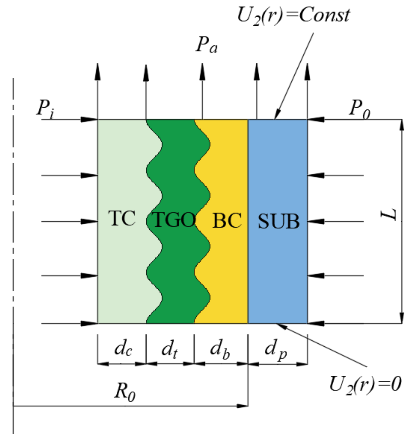
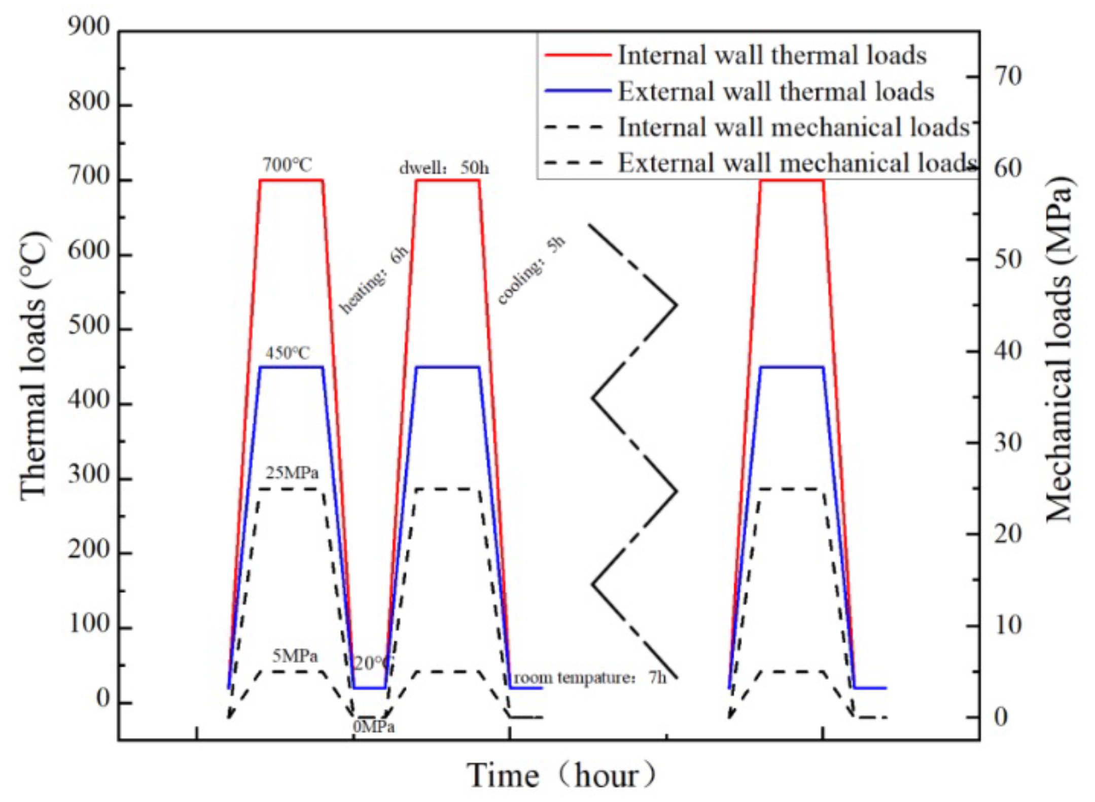
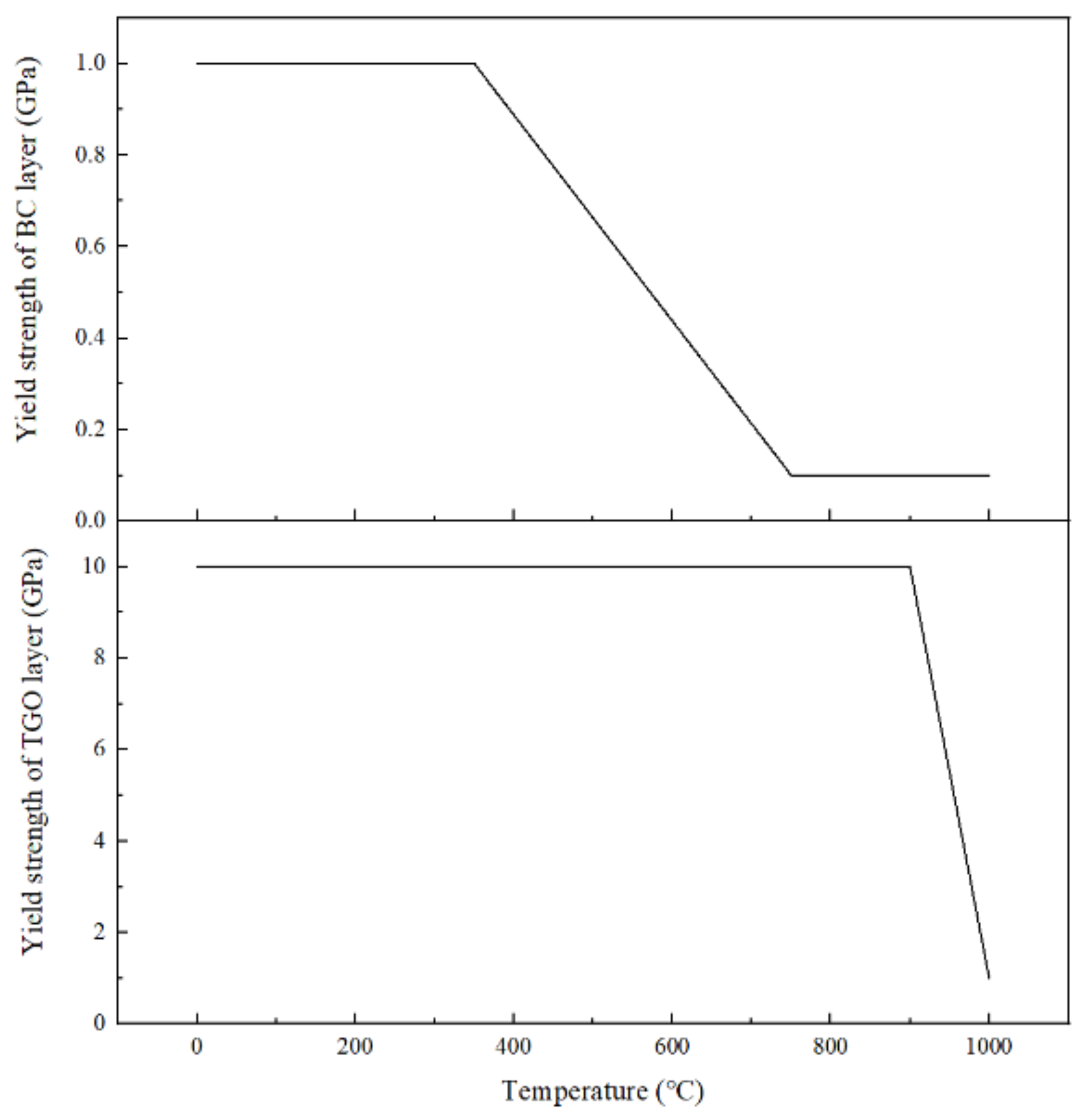
4.2. Boundary Conditions and Materials Parameters

Figure 5 and Figure 6 illustrate the boundary conditions and thermal–mechanical cyclic loads applied in the finite element model. At the lower boundary, symmetric conditions in the axial direction constrain displacement, while periodic conditions at the upper boundary ensure uniform axial displacement across all nodes. The main steam pipe operated at high-temperatures up to 700 °C and cools to 450 °C during operation. Heat transfer via convection between the main steam pipe and cooling steam pipe regulated temperature. The internal and external pipeline pressures were maintained at 25 MPa and 5 MPa, respectively [3,4] The study employed ten heat service cycles to simulate 500 h of operation in a coated dual-pipe system. A room temperature of 20 °C served as the baseline stress state. This initial stress state refers to the post-deposition, room-temperature condition, and that the real substrate temperature during deposition is much higher. Each thermal cycle consisted of four phases: heating the inner and outer pipe walls from 20 °C to 700 °C and 450 °C within 6 h; a 50 h high-temperature operation phase, followed by cooling to room temperature within 5 h; and a 7 h room temperature dwell phase. Mechanical loading within each cycle was similarly divided: increasing inner and outer wall pressures to 25 MPa and 5 MPa over 6 h, a 50 h holding phase, reducing pressures to 0 MPa over 5 h, and a 7 h no-load phase.
In addition, isotropic material properties were assumed for each layer of the TBC system. Material parameters, including the plasticity, thermal expansion coefficient, elasticity modulus, and Poisson’s ratio, are temperature-dependent and were sourced from literature [3,4,18,19]. The values for other material parameters across a broad temperature range were estimated using linear interpolation from existing data, which are detailed in Table 4 and Figure 7. In the current analysis, the creep effects were assumed to be neglected due to the immediate stress–strain evolution during short time frames.

5. Results and Discussion

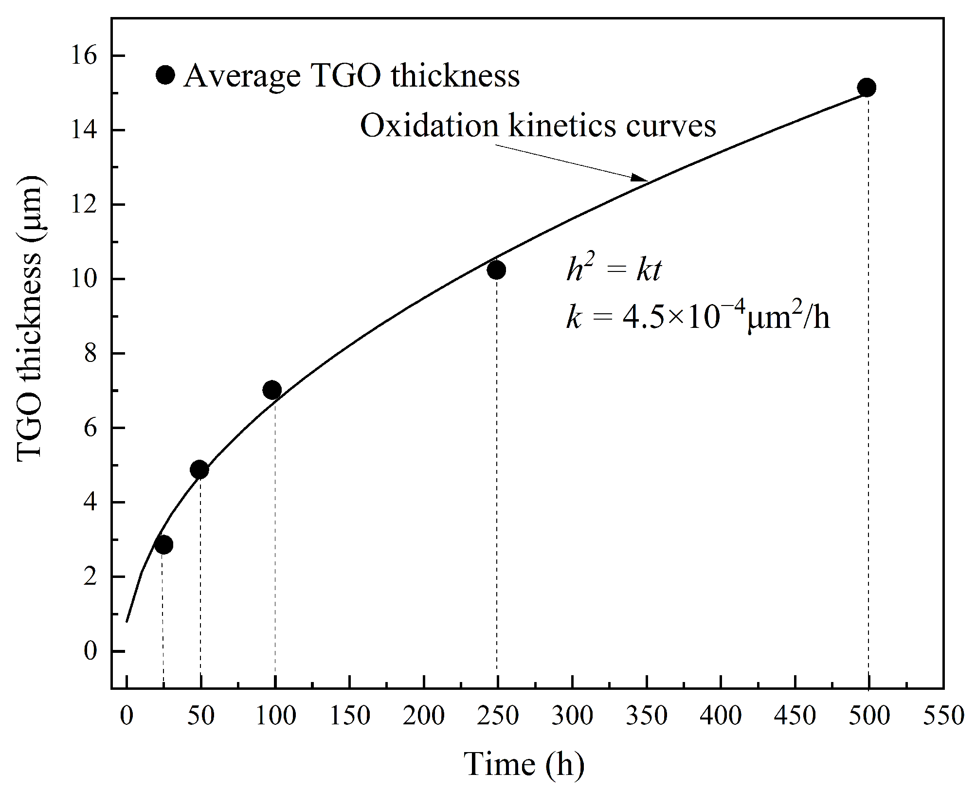
5.1. TGO Growth Kinetics Curve

The oxidation behavior of the TBC specimen at 700°C in a high-temperature water vapor environment is depicted in Figure 8. The curve illustrating oxide thickening is shown following a parabolic oxidation law, as observed from the experimental results. By fitting the experimental data with Equation (1), a value of k 4.5 × 10 4 μ m 2 / h was determined. This coefficient characterizes the rate of oxide thickening over time. Note that this nonlinear thickness variation was studied by modeling the TGO as conversion layers with varying thicknesses. However, the microstructural evolution of pores and their effects on the constitutive relationship of the materials were not explicitly incorporated. For the essence of TGO growth, the microstructural evolution of oxides, including porosity, can be alternatively simulated through the thermo-chemo-mechanical processes occurring during high-temperature exposure.

5.2. Stress and Morphology Evolution with Initial Waviness at TGO Interfaces

This study investigated the impact of initial TGO morphology on interfacial stress distribution and morphology evolution in a coated dual-pipe system during nonlinear TGO growth using finite element simulations. The developed UMAT subroutine modified material parameters and applied growth strain. The finite element model maintained geometric and material parameters while varying interfacial amplitudes ( A = 4 μm, 6 μm, and 8 μm) to analyze their effects. Note that the stresses presented in Section 5.2 and Section 5.3 are in a global frame rather than the local. They may not directly capture the true interfacial stress discontinuities, especially for shear stress components; however, those results could be correlated with the global deformation fields and the interface waviness evolution.
Figure 9 shows the radial and axial stress distributions along TC/TGO and BC/TGO interfaces during the 10th thermal cycle, with various TGO initial morphologies. The mismatch of expansion among constituent layers, intensified by thermo-mechanical loading, generated pronounced stress variance within the TGO layer under transverse and longitudinal growth strains. The axial stresses at the TC/TGO and BC/TGO interfaces were generally larger than the radial stresses during stable operation, peaking near cosine wave crests at the TC/TGO interface adjacent to the TGO side. Increasing the interface amplitude correlated with rising values at both interfaces with increasing TGO growth. For instance, at the TC/TGO interface trough, as the TGO initial amplitude increased from 4 μm to 8 μm, the interfacial stress elevated from −424 MPa to −733 MPa, a 73% increase, being consistent with findings by [23,24].
Studies emphasize [5,6,25] that initial TGO morphology profoundly influences coating system interface evolution, which is determined by volumetric changes leading to interfacial waviness. Figure 10 illustrates the evolution of the interfacial amplitude under varied amplitudes conditions over 10 cycles, indicating continuous amplitude growth consistent with observations by Karlsson and He et al. [16,17,18,19]. Nonlinear TGO growth enlarged the coating interface roughness, aggravating stress concentration and potentially compromising system integrity. Notably, increasing the initial TGO amplitude from 4 μm to 8 μm resulted in amplitude escalation from 0.046 μm to approximately 0.071 μm—a 54% rise. These findings underscore the critical role of the TGO amplitude in governing stress evolution at coating interfaces.

5.3. Stress and Morphology Evolution with Temperature of Cooling Steam

This study investigated the influence of cooling steam temperature on stress distribution and morphology evolution at the interface of a coated dual-pipe system during nonlinear TGO growth. The finite element model maintained consistent geometrical and material parameters while varying cooling steam temperatures (300 °C, 350 °C, 400 °C, and 450 °C) to analyze their effects on interfacial stress and morphology.
Figure 11 illustrates stress distributions along the TC/TGO and BC/TGO interfaces in the radial and axial directions during the steady state of the 10th thermal cycle at different cooling steam temperatures. It reveals that increasing the cooling steam temperature significantly altered axial stress at the TC/TGO interface, reducing from −917 MPa to −717 MPa—a decrease of 21.8%. Similarly, at the BC/TGO interface, the axial stress decreased from −379 MPa to −219 MPa with increasing temperature.
The combined influence of mechanical, thermal, and growth stresses within the coated dual-pipe system, featuring ideal cosine TGO morphology, resulted in complex stress distributions at localized regions of the TC/TGO and BC/TGO interfaces during nonlinear TGO growth. As the cooling steam temperature rose, while the mechanical and growth stresses remained relatively constant, thermal stresses evolved, leading to noticeable changes in the axial stresses at the TC/TGO and BC/TGO interfaces. Higher cooling steam temperatures effectively mitigated the axial stress values at these interfaces, which were crucial for maintaining the structural integrity of the coating system.
Furthermore, Figure 12 depicts the evolution of interfacial morphology after 10 thermal cycles at varying cooling steam temperatures. Since the cooling steam temperature did not directly impact nonlinear TGO growth, its influence on interfacial morphology evolution remained limited. For instance, the amplitude evolution changed by less than 1% when the cooling temperature increased from 300 to 450 °C after the 10th thermal cycle, as depicted in Figure 12. This stability was paramount in ensuring the robustness of the coating system. These findings underscore the critical role of the cooling steam temperature in managing stress distribution and preserving the structural integrity of the coated dual-pipe systems during TGO growth.

6. Concluding Remarks and Future Directions

A numerical simulation method for the nonlinear growth of TGOs has been proposed and applied to a novel coated steam dual-pipe system, and several conclusions have been drawn:
(1)
The oxidation kinetics of TBCs in a high-temperature water vapor environment at 700 °C followed a parabolic growth pattern. The growth rate of the TGO layer decreased over time, with an oxidation rate constant taking k 4.5 × 10 4 μ m 2 / h .
(2)
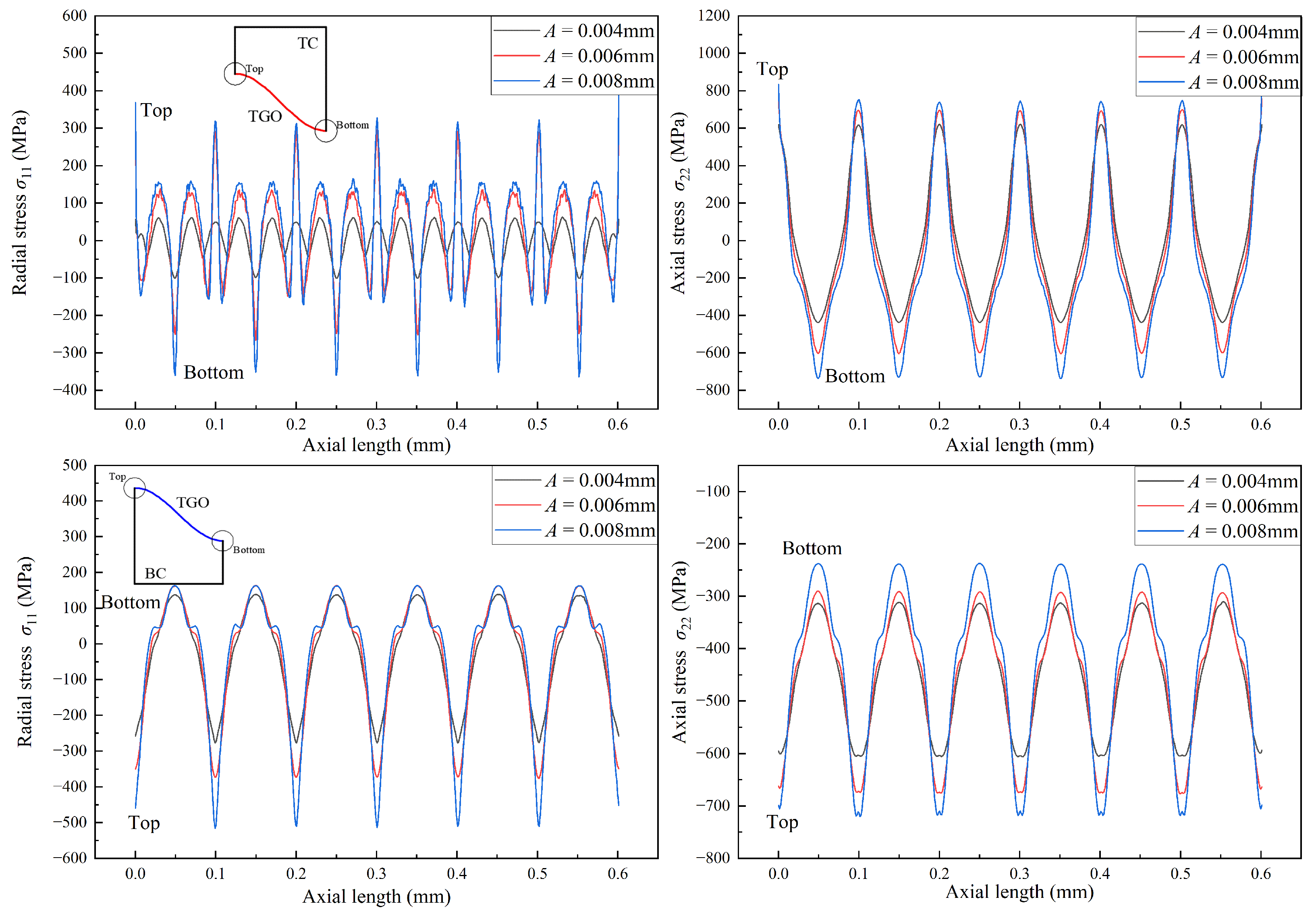
As the TGO layer grew, its interfacial amplitude increase, resulting in greater interfacial curvature. This curvature enhanced the stress concentration at the TC/TGO and BC/TGO interfaces, significantly influencing the interfacial stress of the coated system.
(3)
The temperature of the cooling steam substantially affected the stress distribution at the TC/TGO and BC/TGO interfaces by altering the thermal stress within the coating system. When the cooling steam temperature rose from 300 °C to 450 °C, the stress values at the TC/TGO and BC/TGO interfaces decreased from −917 MPa and −379 MPa to −717 MPa and −219 MPa, respectively.
From a mechanical and materials perspective, the nonlinear growth of TGO under high-temperature service conditions is a complex interaction of diffusion, oxidation, and viscous–plastic deformation. This scenario exemplifies a thermal–mechanical–chemical coupling problem. To comprehensively understand the impact of TGO growth on the stress and strain fields at the coating interface, future research should focus on the thermal–chemical–mechanical coupling mechanisms of TBC oxidation. It would be aimed to develop a multifield model that accurately represents the diffusion, oxidation, and viscous–plastic deformation behaviors of the TBC interface under varying temperatures. In addition, future research should consider wavy interface geometries extracted from experimental observations, which often exhibit continuous curvature changes. Incorporating such realistic interface morphologies into simulations would provide deeper insights into the stress distribution and failure mechanisms of TBCs. By combining experimentally observed geometries with multifield modeling, the analysis could better capture the true complexity of interfacial interactions and the role of TGO growth in coating performance and durability.

Author Contributions

B.Y.: Writing—review and editing, Conceptualization, Supervision; K.W.: Writing—original draft, Methodology, Investigation, Formal Analysis; X.G.: Writing—review and editing, Conceptualization, Supervision, Funding acquisition; J.G.: Validation; P.C. Investigation, Validation. All authors have read and agreed to the published version of the manuscript.

Funding

This research was supported by the National Natural Science Foundation of China (Grant No. 52265021, 52465018) and the Central Government in Guidance of Local Science and Technology Development (Grant No. 2022ZY0074).

Institutional Review Board Statement

Not applicable.

Informed Consent Statement

Not applicable.

Data Availability Statement

The original contributions presented in this study are included in the article; further inquiries can be directed to the corresponding authors.

Conflicts of Interest

The authors declare no conflicts of interest.

References

  1. Jiang, J.; Ye, B.; Liu, J. Research on the peak of CO2 emissions in the developing world: Current progress and future prospect. Appl. Energy 2019, 235, 186–203. [Google Scholar] [CrossRef]
  2. Jianlan, Z.; Bo, A.; Yuqi, G. Thermal stress analysis on thermal barrier coatings based on real three-dimensional structure of thermally grown oxide. Rare Met. Mater. Eng. 2018, 47, 2100–2106. [Google Scholar]
  3. Guo, X.; Sun, W.; Becker, A.; Morris, A.; Pavier, M.; Flewitt, P.; Tierney, M.; Wales, C. Thermal and stress analyses of a novel coated steam dual pipe system for use in advanced ultra-supercritical power plant. Int. J. Press. Vessels Pip. 2019, 176, 103933. [Google Scholar] [CrossRef]
  4. Guo, X.; Benaarbia, A.; Sun, W.; Becker, A.; Morris, A.; Pavier, M.; Flewitt, P.; Tierney, M.; Wales, C. Optimisation and thermo-mechanical analysis of a coated steam dual pipe system for use in advanced ultra-supercritical power plant. Int. J. Press. Vessels Pip. 2020, 186, 104157. [Google Scholar] [CrossRef]
  5. Evans, A.G.; Mumm, D.; Hutchinson, J.; Meier, G.; Pettit, F. Mechanisms controlling the durability of thermal barrier coatings. Prog. Mater. Sci. 2001, 46, 505–553. [Google Scholar] [CrossRef]
  6. Wang, T.; Fan, X.; Sun, Y.; Su, L.; Song, Y.; Lv, B. The stresses and cracks in thermal barrier coating system: A review. Guti Lixue Xuebao/Acta Mech. Solida Sin. 2016, 37, 477–517. [Google Scholar]
  7. Bai, Y.; Ding, C.; Li, H.; Han, Z.; Ding, B.; Wang, T.; Yu, L. Isothermal oxidation behavior of supersonic atmospheric plasma-sprayed thermal barrier coating system. J. Therm. Spray Technol. 2013, 22, 1201–1209. [Google Scholar] [CrossRef]
  8. Liu, X.; Wang, T.; Li, C.; Lime, R.S.; Patnaik, P.C. Formation and growth behavior of TGO in air plasma sprayed thermal barrier coatings at high temperature. Surf. Technol. 2015, 11, 91–96. [Google Scholar]
  9. Poza, P.; Gómez-García, J.; Múnez, C. TEM analysis of the microstructure of thermal barrier coatings after isothermal oxidation. Acta Mater. 2012, 60, 7197–7206. [Google Scholar] [CrossRef]
  10. Li, Z.; Qian, S.; Wang, W.; Liu, J. Microstructure and oxidation resistance of magnetron-sputtered nanocrystalline NiCoCrAlY coatings on nickel-based superalloy. J. Alloys Compd. 2010, 505, 675–679. [Google Scholar] [CrossRef]
  11. Niranatlumpong, P.; Ponton, C.; Evans, H. The failure of protective oxides on plasma-sprayed NiCrAlY overlay coatings. Oxid. Met. 2000, 53, 241–258. [Google Scholar] [CrossRef]
  12. Tuan, W.; Wu, H.; Chen, R. Effect of sintering atmosphere on the mechanical properties of NiAl2O3 composites. J. Eur. Ceram. Soc. 1997, 17, 735–741. [Google Scholar] [CrossRef]
  13. Kumar, A.; Moledina, J.; Liu, Y.; Chen, K.; Patnaik, P.C. Nano-micro-structured 6%–8% YSZ thermal barrier coatings: A comprehensive review of comparative performance analysis. Coatings 2021, 11, 1474. [Google Scholar] [CrossRef]
  14. Wagner, C. Diffusion and high temperature oxidation of metals. At. Mov. 1951, 165. [Google Scholar]
  15. Freborg, A.; Ferguson, B.; Brindley, W.; Petrus, G. Modeling oxidation induced stresses in thermal barrier coatings. Mater. Sci. Eng. A 1998, 245, 182–190. [Google Scholar] [CrossRef]
  16. Karlsson, A.M.; Evans, A. A numerical model for the cyclic instability of thermally grown oxides in thermal barrier systems. Acta Mater. 2001, 49, 1793–1804. [Google Scholar] [CrossRef]
  17. Karlsson, A.M.; Levi, C.; Evans, A. A model study of displacement instabilities during cyclic oxidation. Acta Mater. 2002, 50, 1263–1273. [Google Scholar] [CrossRef]
  18. He, M.; Hutchinson, J.; Evans, A. Large deformation simulations of cyclic displacement instabilities in thermal barrier systems. Acta Mater. 2002, 50, 1063–1073. [Google Scholar] [CrossRef]
  19. He, M.; Hutchinson, J.; Evans, A. Simulation of stresses and delamination in a plasma-sprayed thermal barrier system upon thermal cycling. Mater. Sci. Eng. A 2003, 345, 172–178. [Google Scholar] [CrossRef]
  20. Clarke, D.R. The lateral growth strain accompanying the formation of a thermally grown oxide. Acta Mater. 2003, 51, 1393–1407. [Google Scholar] [CrossRef]
  21. Rhines, F.; Wolf, J. The role of oxide microstructure and growth stresses in the high-temperature scaling of nickel. Metall. Trans. 1970, 1, 1701–1710. [Google Scholar] [CrossRef]
  22. Su, L.; Zhang, W.; Sun, Y.; Wang, T. Effect of TGO creep on top-coat cracking induced by cyclic displacement instability in a thermal barrier coating system. Surf. Coatings Technol. 2014, 254, 410–417. [Google Scholar] [CrossRef]
  23. Ding, J.; Li, F.X.; Kang, K.J. Numerical simulation of displacement instabilities of surface grooves on an alumina forming alloy during thermal cycling oxidation. J. Mech. Sci. Technol. 2009, 23, 2308–2319. [Google Scholar] [CrossRef]
  24. Wang, X.; Atkinson, A.; Chirivì, L.; Nicholls, J.R. Evolution of stress and morphology in thermal barrier coatings. Surf. Coatings Technol. 2010, 204, 3851–3857. [Google Scholar] [CrossRef]
  25. Abdelgawad, A.; Al-Athel, K. Effect of TGO thickness, pores, and creep on the developed residual stresses in thermal barrier coatings under cyclic loading using SEM image-based finite element model. Ceram. Int. 2021, 47, 20064–20076. [Google Scholar] [CrossRef]
Figure 1. Schematic diagram of the coated steam dual-pipe system [3,4].
Coatings 14 01478 g001
Figure 2. Schematic diagram of high-temperature water vapor oxidation testing.
Coatings 14 01478 g002
Figure 3. Growth strain imposition over thermal cycles.
Coatings 14 01478 g003
Figure 4. UMAT subroutine workflow for TGO nonlinear growth.
Coatings 14 01478 g004
Figure 5. Schematic diagram of the geometry and boundary conditions for the axisymmetric FE model ( R 0 = 120 mm, d p = 30 mm, d c = 0.8 mm, d t = 0.001 mm, d b = 0.199 mm, L = 0.6 mm, P i = 25 MPa, P o = 5 MPa).
Coatings 14 01478 g005
Figure 6. Thermal–mechanical cycle loads [3,4].
Coatings 14 01478 g006
Figure 7. Plasticity parameters of TGO and BC layers [18,19].
Coatings 14 01478 g007
Figure 8. TGO growth kinetic curve during 700 °C water vapor oxidation testing.
Coatings 14 01478 g008
Figure 9. Influence of TGO initial interfacial morphology on stress distribution at TC/TGO and BC/TGO interfaces in the direction of the radial stress and axial stress in HT dwell.
Coatings 14 01478 g009
Figure 10. Influence of TGO initial interfacial morphology on the interfacial morphology evolution.
Coatings 14 01478 g010
Figure 11. Influence of cooling temperature on stress distribution at TC/TGO and BC/TGO interfaces in the direction of the radial stress and axial stress in HT dwell.
Coatings 14 01478 g011
Figure 12. Influence of cooling temperature on the interfacial morphology evolution.
Coatings 14 01478 g012
Table 1. Chemical composition of P92 steel (mass fraction, %).
CMnPSSiCrWMoV
0.1140.3920.0110.0040.3159.211.930.4750.189
NbCMnPNBNiAl
0.0730.1140.3920.010.0370.0030.2750.011
Table 2. Changes in SDV value of the two-layer transformation layer with the cycle.
First Thermal CycleSecond Thermal Cycle
HeatingHT dwellCoolingRT dwellHeatingHT dwellCoolingRT dwell
Step 1Step 2Step 3Step 4Step 5Step 6Step 7Step 8
Conversion layer C101111111
Conversion layer C200000111
Table 3. Conversion layer thickness and lateral growth strain.
Layer No.Time (Hour) Δ h (mm)Lateral Growth Strain
000.00000.0000
1500.00470.0707
21000.00200.0293
31500.00150.0225
42000.00130.0189
52500.00110.0167
63000.00100.0151
73500.00090.0139
84000.00090.0129
94500.00080.0121
105000.00080.0115
Table 4. Temperature-dependent material properties for constituent layers in the TBC system [3,4,18,19].
MaterialTemp.E ν Yield StrengthDensityCTEConductivitySpecific Heat
(°C)(GPa)(MPa)(kg/m3)(10−6/°C)(W/m°C)(J/(kg°C))
8YSZ202040.1 60379.681.2500
8001790.11 9.88
TGO204000.2310003984810755
10003250.251 9.34
NiCoCrAlY202000.3868771112.55.8628
8001450.32191 14.314.5
P92202180.34887770 26440
100213 461 10.927480
200207 441 11.328510
300199 427 11.728550
400190 396 12.129630
450186 12.129630
500181 360 12.330660
550175 331 12.430710
600168 285 12.630770
650162 206 12.730860
Disclaimer/Publisher’s Note: The statements, opinions and data contained in all publications are solely those of the individual author(s) and contributor(s) and not of MDPI and/or the editor(s). MDPI and/or the editor(s) disclaim responsibility for any injury to people or property resulting from any ideas, methods, instructions or products referred to in the content.

