

Influence of Axle Weight and Frequency on the Tribological Properties of Laser-Repaired 316L Stainless Steel Coatings in Railway Wheel Tread Braking


Abstract
1. Introduction
2. Materials and Methods
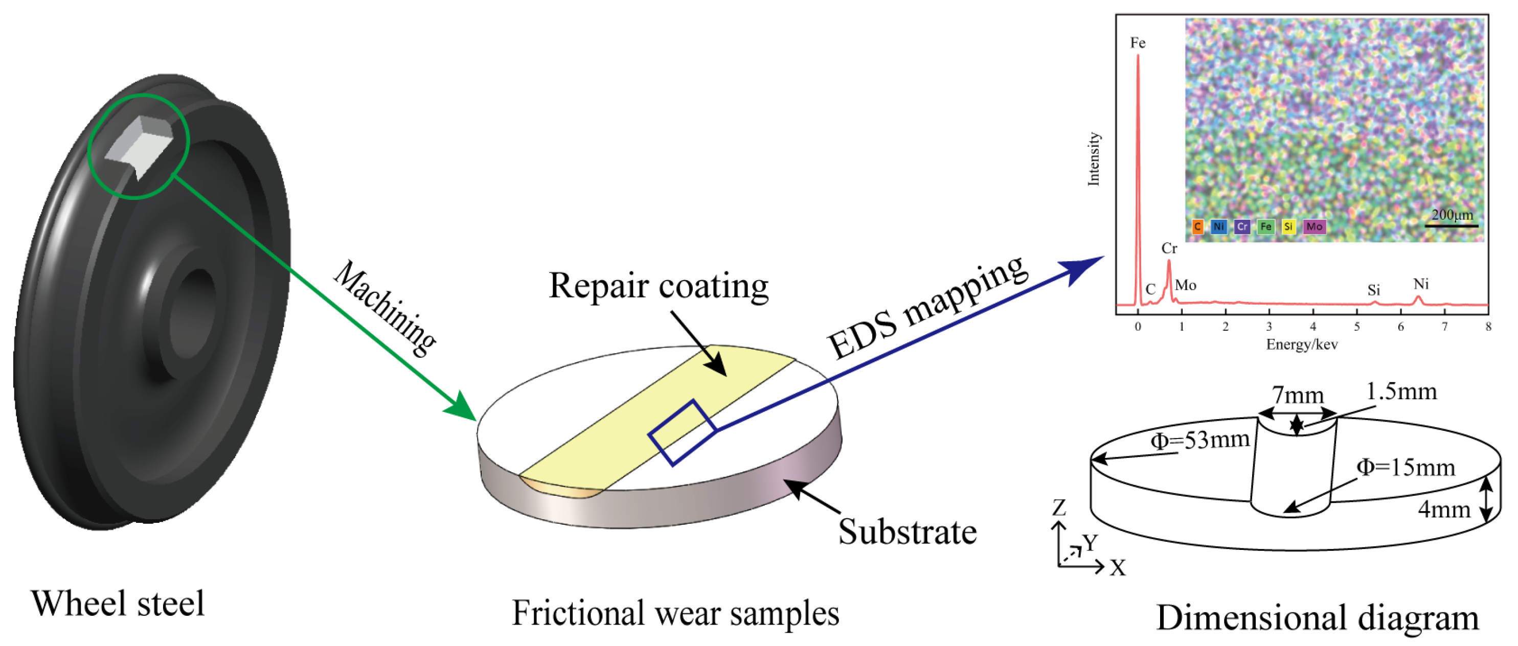
2.1. Materials and Specimen
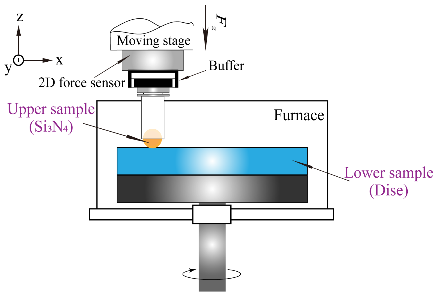
2.2. Friction Test
2.3. Characterization
3. Results
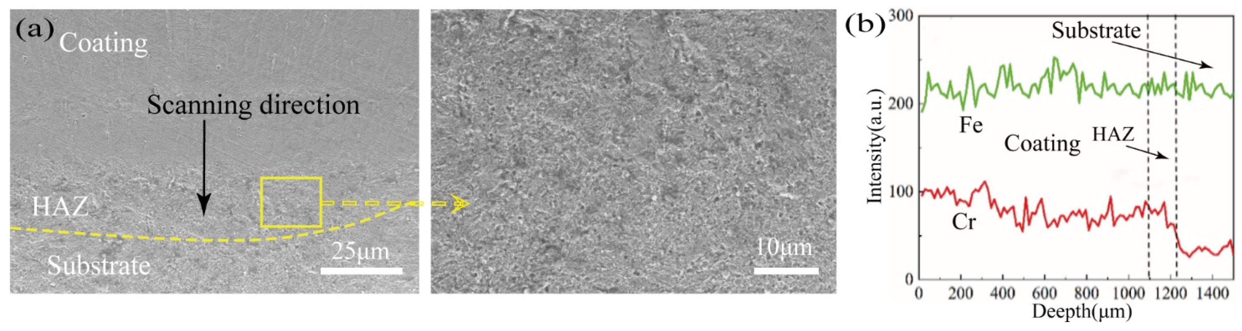
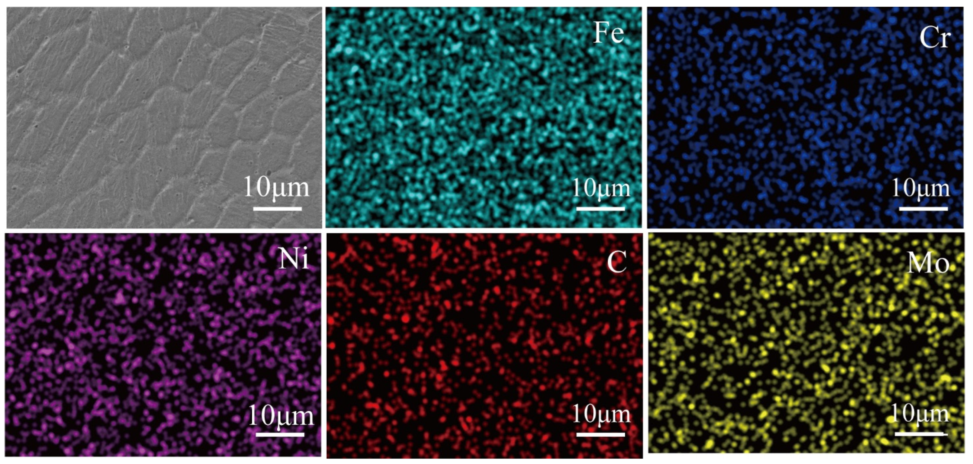
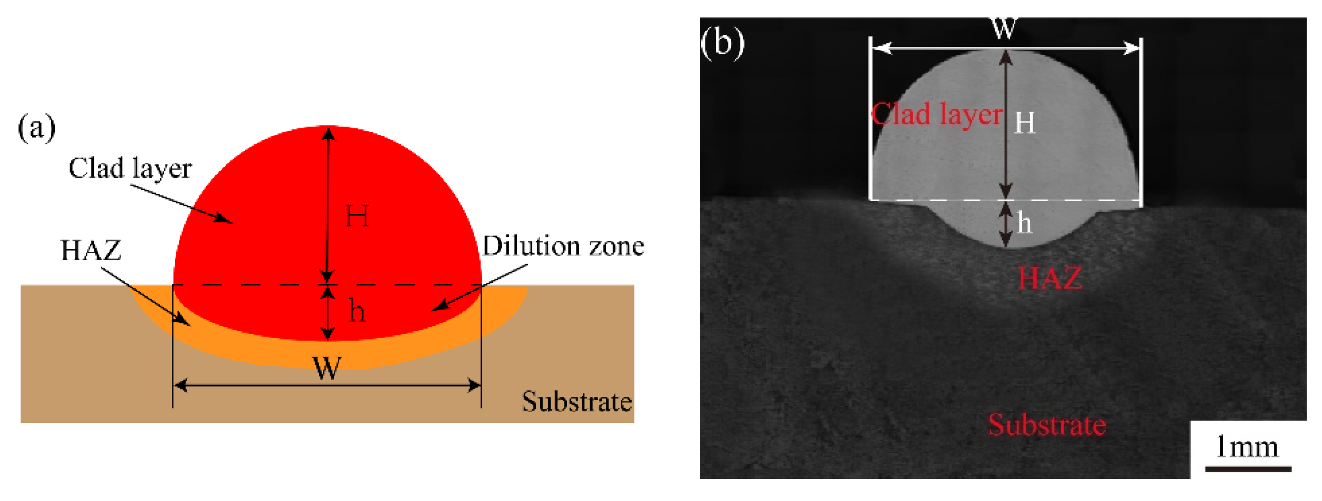
3.1. Microstructure
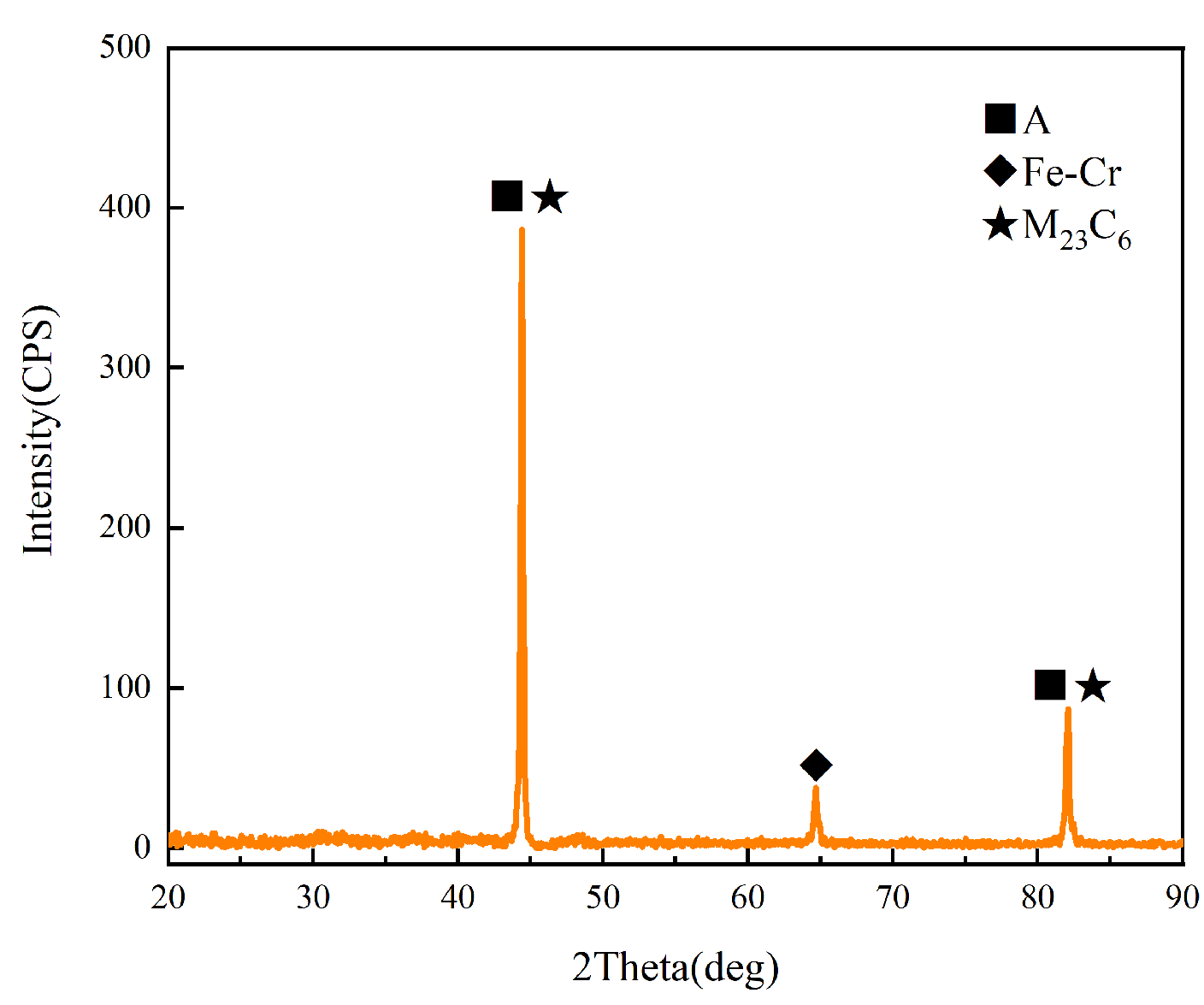
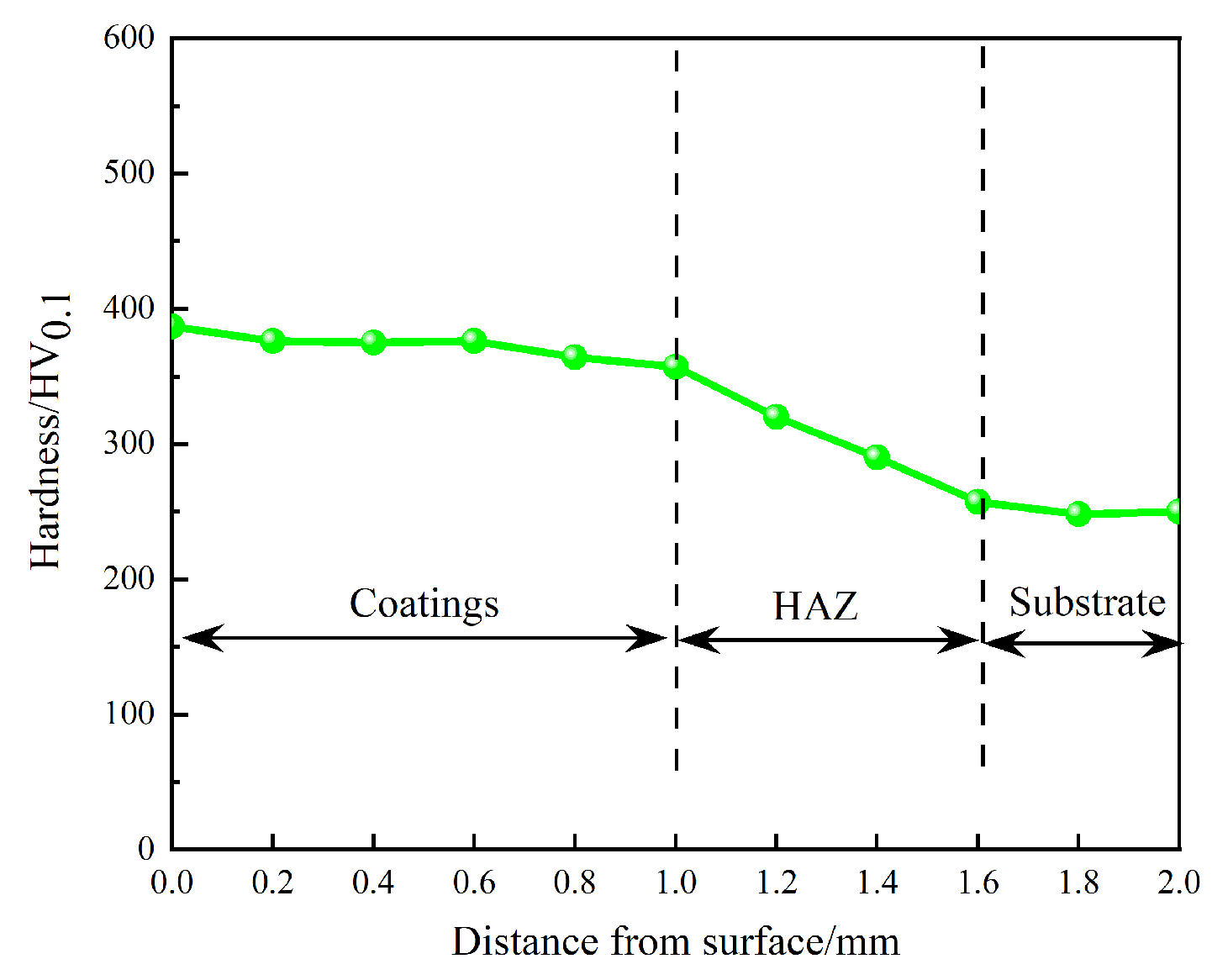
3.2. Phase Analysis and Microhardness
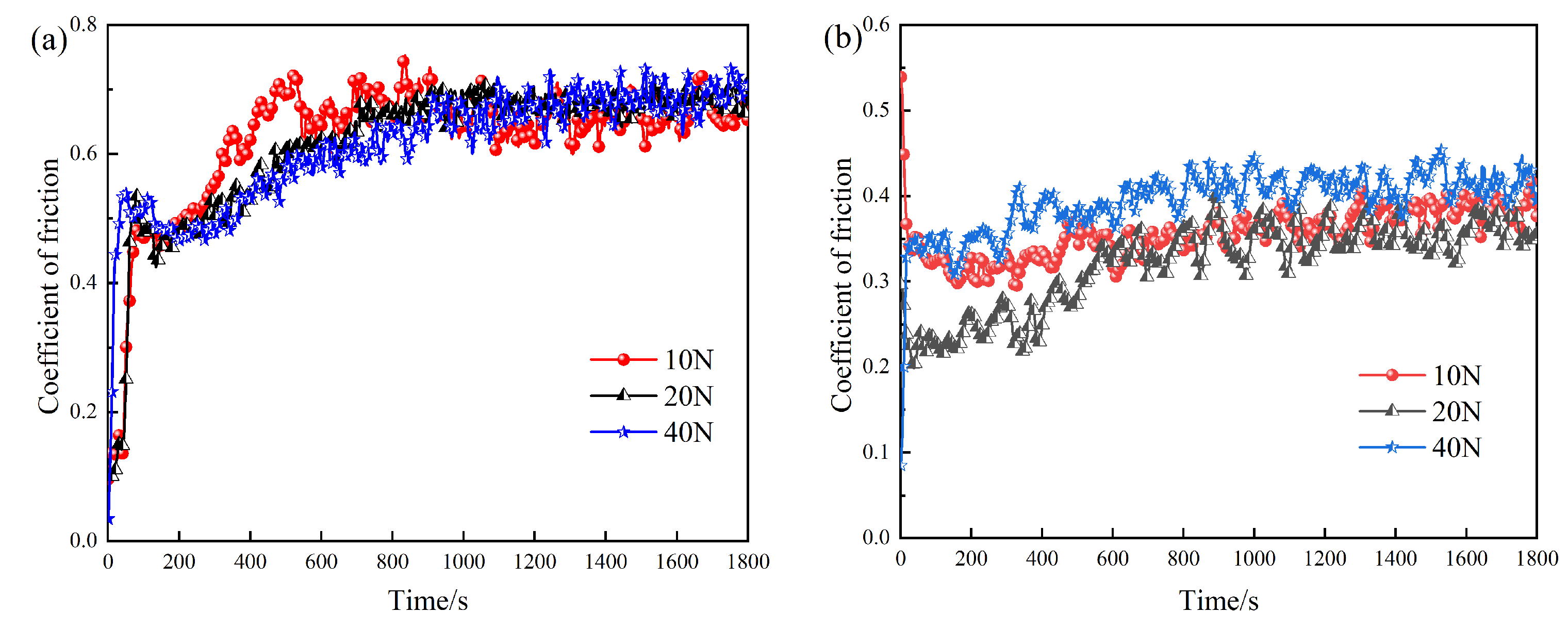
3.3. Influence of Axle Weight
3.4. Influence of Braking Frequency
4. Conclusions
- (1)
- The microstructure on the surface of the 316L stainless steel cladding repair coating is dense and uniform, without defects, such as pores and cracks. The cladding layer is composed of uniform cellular crystals, and the crystalline phase is mainly composed of austenite, Fe-Cr, and carbide.
- (2)
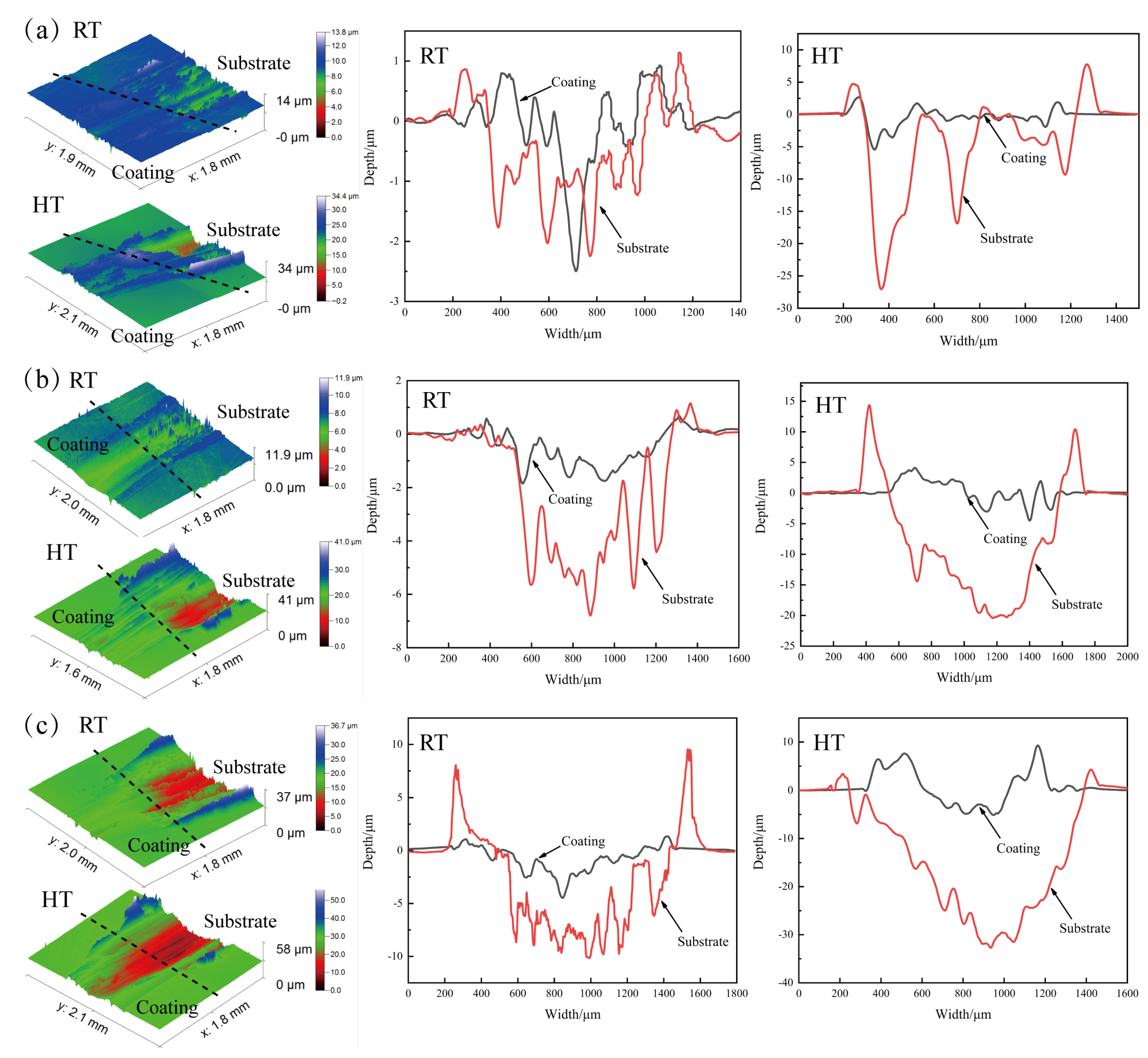
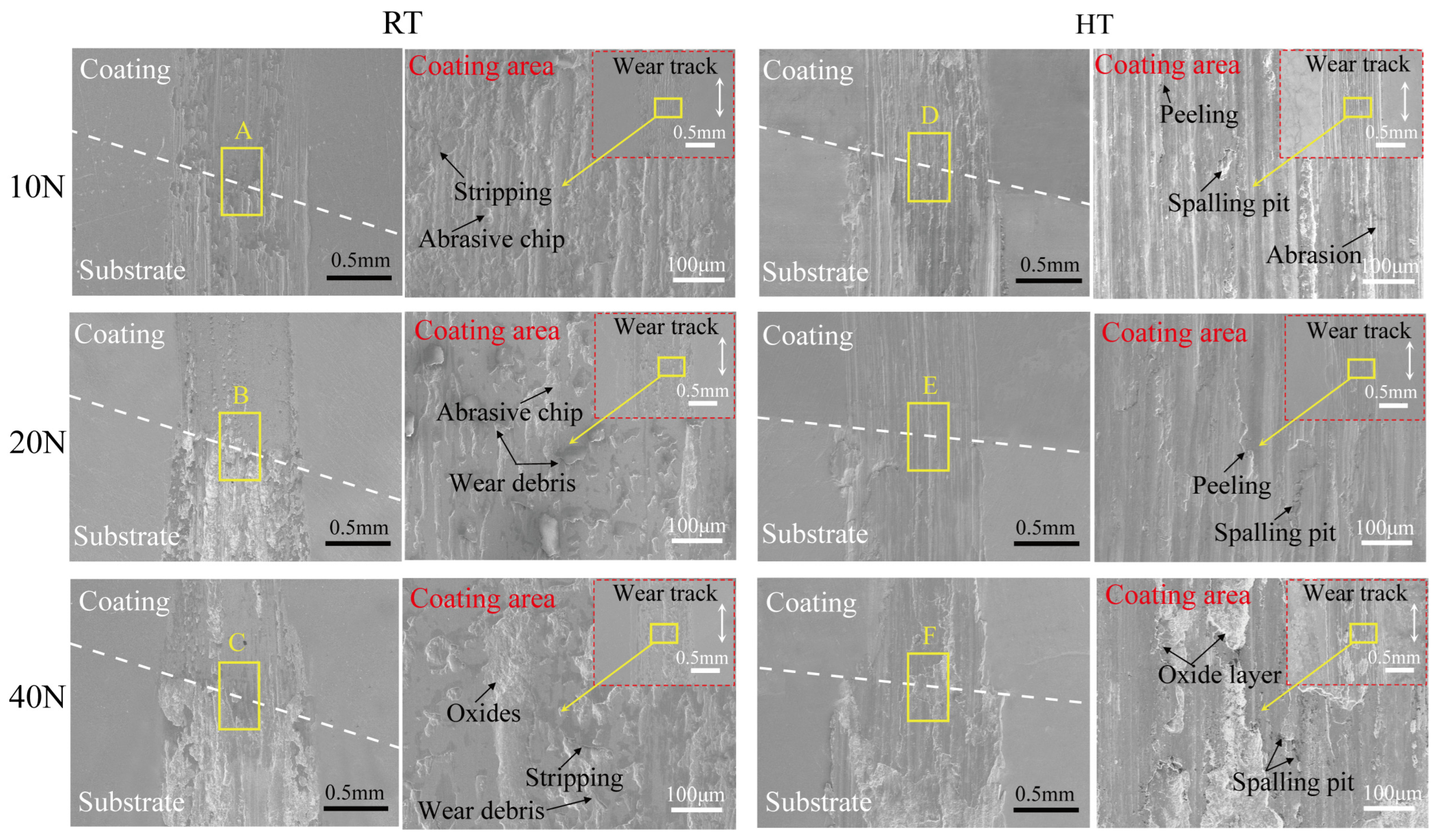
- As the heavy load of the contact shaft increases, the impact on the friction coefficient under a room temperature environment changes slightly. Regardless of whether it is room temperature or high temperature, the wear rate of the repaired sample gradually increases, with the maximum values in the coating and substrate areas being approximately 2.36 × 10⁻⁵ mm3/(N·m) and 6.23 × 10⁻⁵ mm3/(N·m), respectively. Increasing the load from 10 N to 40 N, the coating wear surface switches from slight delamination and plowing at the beginning to severe plastic deformation with some flaking pits on the surface, the wear becomes severe, and the wear mechanism changes from abrasive wear with a small amount of adhesive wear to the joint coupling of adhesive wear and abrasive wear.
- (3)
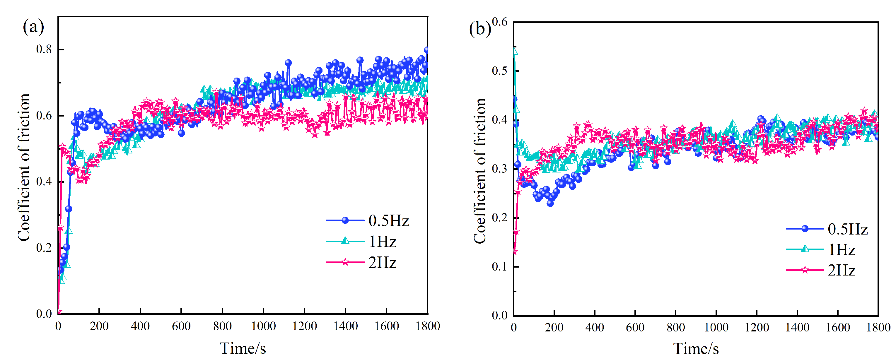
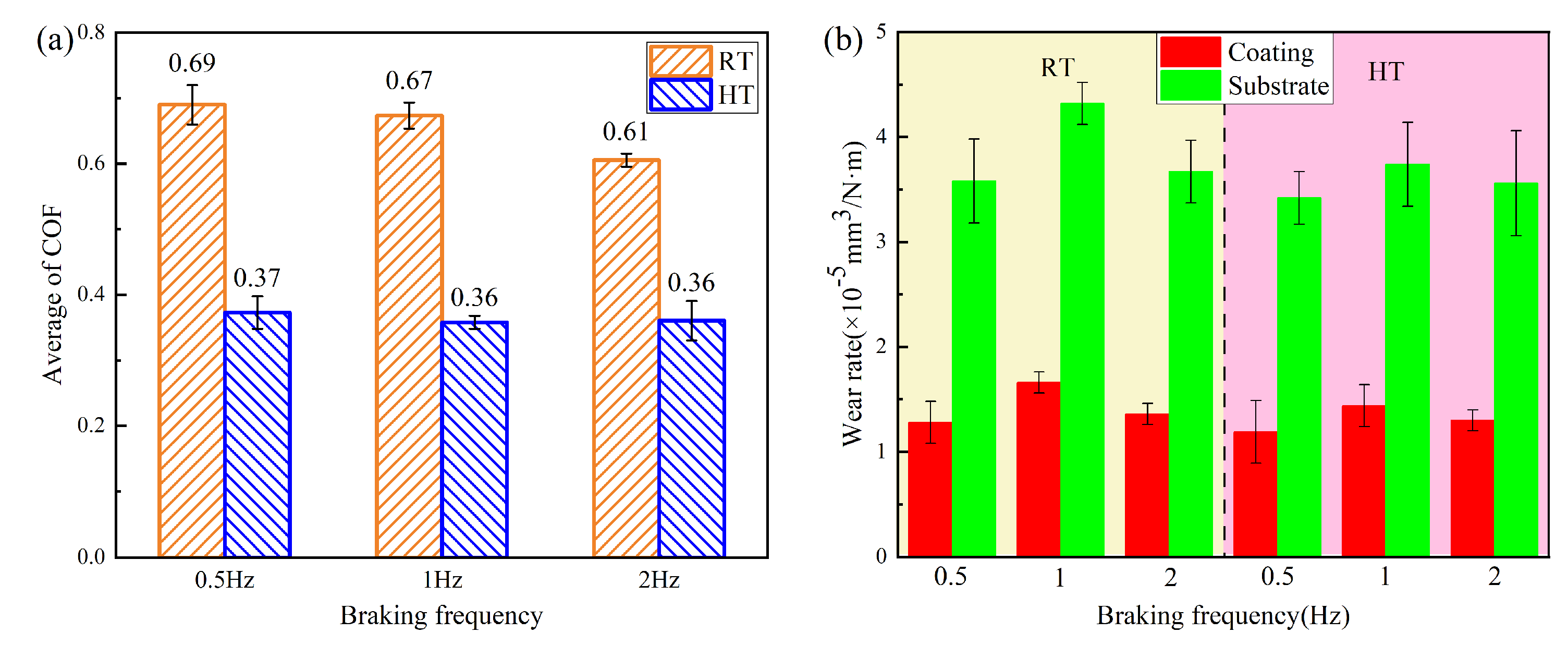
- As the braking frequency increases, the impact on the friction coefficient in high-temperature environments changes slightly. In the two temperature environments, the wear rates of the repaired samples show a pattern of first increasing and then decreasing. The lowest wear rates of the coating area at room temperature and high temperature were 1.28 × 10⁻⁵ mm3/(N·m) and 1.19 × 10⁻⁵ mm3/(N·m), respectively. When the frequency is 0.5 Hz, peeling and wear marks appear on the worn surface of the repair coating area, which is manifested as abrasive wear. At a frequency of 1 Hz, the worn surface has a peeling layer and a large amount of wear debris, and the wear mechanism is abrasive wear and adhesive wear. When the test frequency is increased to 2 Hz, the grinding surface shows many peeling pits and some oxides, which together show the characteristics of adhesive wear and severe abrasive wear.
- (4)
- The axle load and braking frequency conditions of the train wheel tread in service have a certain impact on the friction and wear performance of the local repair cladding layer.
Author Contributions
Funding
Institutional Review Board Statement
Informed Consent Statement
Data Availability Statement
Conflicts of Interest
References
- Kwon, S.J.; Seo, J.W.; Jun, H.K.; Lee, D.H. Damage evaluation regarding to contact zones of high-speed train wheel subjected to thermal fatigue. Eng. Fail. Anal. 2015, 55, 327–342. [Google Scholar] [CrossRef]
- Nikas, D.; Ahlström, J.; Malakizadi, A. Mechanical properties and fatigue behaviour of railway wheel steels as influenced by mechanical and thermal loadings. Wear 2016, 366, 407–415. [Google Scholar] [CrossRef]
- Mazzù, A.; Petrogalli, C.; Faccoli, M. An integrated model for competitive damage mechanisms assessment in railway wheel steels. Wear 2015, 322, 181–191. [Google Scholar] [CrossRef]
- Li, S.; Hu, Q.W.; Zeng, X.Y.; Ji, S.Q. Effect of carbon content on the microstructure and the cracking susceptibility of Fe-based laser-clad layer. Appl. Surf. Sci. 2005, 240, 63–70. [Google Scholar] [CrossRef]
- Gao, Z.; Wang, L.; Wang, Y.; Lyu, F.; Zhan, X. Crack defects and formation mechanism of FeCoCrNi high entropy alloy coating on TC4 titanium alloy prepared by laser cladding. J. Alloys Compd. 2022, 903, 163905. [Google Scholar] [CrossRef]
- Yang, J.; Bai, B.; Ke, H.; Cui, Z.; Liu, Z.; Zhou, Z.; Xu, H.C.; Xiao, J.H.; Li, H. Effect of metallurgical behavior on microstructure and properties of FeCrMoMn coatings prepared by high-speed laser cladding. Opt. Laser Technol. 2021, 144, 107431. [Google Scholar] [CrossRef]
- Liu, H.; Gao, Q.; Dai, J.; Chen, P.; Gao, W.; Hao, J.; Yang, H. Microstructure and high-temperature wear behavior of CoCrFeNiWx high-entropy alloy coatings fabricated by laser cladding. Tribol. Int. 2022, 172, 107574. [Google Scholar] [CrossRef]
- Xie, Y.; Zhang, J. Chloride-induced stress corrosion cracking of used nuclear fuel welded stainless steel canisters: A review. J. Nucl. Mater. 2015, 466, 85–93. [Google Scholar] [CrossRef]
- Ibrahim, M.Z.; Sarhan, A.A.; Kuo, T.; Yusof, F.; Hamdi, M.; Lee, T. Developing a new laser cladded FeCrMoCB metallic glass layer on nickel-free stainless-steel as a potential superior wear-resistant coating for joint replacement implants. Surf. Coat. Technol. 2020, 392, 125755. [Google Scholar] [CrossRef]
- Seo, J.W.; Kim, J.C.; Kwon, S.J.; Jun, H.K. Effects of laser cladding for repairing and improving wear of rails. Int. J. Precis. Eng. Manuf. 2019, 20, 1207–1217. [Google Scholar] [CrossRef]
- Guo, H.M.; Wang, Q.; Wang, W.J.; Guo, J.; Liu, Q.Y.; Zhu, M.H. Investigation on wear and damage performance of laser cladding Co-based alloy on single wheel or rail material. Wear 2015, 328, 329–337. [Google Scholar] [CrossRef]
- Lewis, S.; Lewis, R.; Goodwin, P.; Fretwell-Smith, S.; Fletcher, D.; Murray, K.; Jaiswal, J. Full-scale testing of laser clad railway track; Case study–Testing for wear, bend fatigue and insulated block joint lipping integrity. Wear 2017, 376, 1930–1937. [Google Scholar] [CrossRef]
- Wang, W.; Fu, Z.; Cao, X.; Guo, J.; Liu, Q.; Zhu, M. The role of lanthanum oxide on wear and contact fatigue damage resistance of laser cladding Fe-based alloy coating under oil lubrication condition. Tribol. Int. 2016, 94, 470–478. [Google Scholar] [CrossRef]
- Zhang, H.; Liu, Y.; Bai, X.; Zhao, W.; Zhang, P.; Rao, W.F. Laser cladding highly corrosion-resistant nano/submicron ultrafine-grained Fe-based composite layers. Surf. Coat. Technol. 2021, 424, 127636. [Google Scholar] [CrossRef]
- Zhu, Y.; Yang, Y.; Mu, X.; Wang, W.; Yao, Z.; Yang, H. Study on wear and RCF performance of repaired damage railway wheels: Assessing laser cladding to repair local defects on wheels. Wear 2019, 430, 126–136. [Google Scholar] [CrossRef]
- Liu, Y.; Ding, Y.; Yang, L.; Sun, R.; Zhang, T.; Yang, X. Research and progress of laser cladding on engineering alloys: A review. J. Manuf. Process. 2021, 66, 341–363. [Google Scholar] [CrossRef]
- Apolinario, L.; Wallerstein, D.; Montealegre, M.; Urtiga Filho, S.; Torres, E.; Hermenegildo, T.; Santos, T. Predominant solidification modes of 316 austenitic stainless steel coatings deposited by laser cladding on 304 stainless steel substrates. Metall. Mater. Trans. A 2019, 50, 3617–3628. [Google Scholar] [CrossRef]
- Moyar, G.; Stone, D. An analysis of the thermal contributions to railway wheel shelling. Wear 1991, 144, 117–138. [Google Scholar] [CrossRef]
- Teimourimanesh, S.; Vernersson, T.; Lunden, R. Modelling of temperatures during railway tread braking: Influence of contact conditions and rail cooling effect. Proc. Inst. Mech. Eng. F-J. Rai. 2014, 228, 93–109. [Google Scholar] [CrossRef]
- Avril, L.; Courant, B.; Hantzpergue, J.J. Tribological performance of α-Fe (Cr)-Fe2B-FeB and α-Fe (Cr)-h-BN coatings obtained by laser melting. Wear 2006, 260, 351–360. [Google Scholar] [CrossRef]
- Amano, R.; Rohatgi, P. Laser engineered net shaping process for SAE 4140 low alloy steel. Mater. Sci. Eng. A 2011, 528, 6680–6693. [Google Scholar] [CrossRef]
- Lee, Y.; Nordin, M.; Babu, S.S.; Farson, D.F. Effect of fluid convection on dendrite arm spacing in laser deposition. Metall. Mater. Trans. B 2014, 45, 1520–1529. [Google Scholar] [CrossRef]
- Lu, S.Y.; Yao, K.F.; Chen, Y.B.; Wang, M.H.; Liu, X.; Ge, X. The effect of tempering temperature on the microstructure and electrochemical properties of a 13 wt.% Cr-type martensitic stainless steel. Electrochim. Acta 2015, 165, 45–55. [Google Scholar] [CrossRef]
- Taheri, M.; Halvaee, A.; Kashani-Bozorg, S.F. Hot cracking of GTD-111 nickel-based superalloy welded by pulsed Nd: YAG laser. Metallogr. Microstruct. Anal. 2020, 9, 16–32. [Google Scholar] [CrossRef]
- Huang, Y.; Yang, S.; Gu, J.; Xiong, Q.; Duan, C.; Meng, X.; Fang, Y. Microstructure and wear properties of selective laser melting 316L. Mater. Chem. Phys. 2020, 254, 123487. [Google Scholar] [CrossRef]
- Zhao, S.; Taheri, M.; Shirvani, K.; Naserlouei, M.; Beirami, K.; Paidar, M.; Sai, W. Microstructure of NbMoTaTiNi refractory high-entropy alloy coating fabricated by ultrasonic field-assisted laser cladding process. Coatings 2023, 13, 995. [Google Scholar] [CrossRef]
- Wang, X.; Muniz-Lerma, J.A.; Sánchez-Mata, O.; Shandiz, M.A.; Brochu, M. Microstructure and mechanical properties of stainless steel 316L vertical struts manufactured by laser powder bed fusion process. Mater. Sci. Eng. A 2018, 736, 27–40. [Google Scholar] [CrossRef]
- Bartolomeu, F.; Buciumeanu, M.; Pinto, E.; Alves, N.; Carvalho, O.; Silva, F.; Miranda, G. 316L stainless steel mechanical and tribological behavior—A comparison between selective laser melting, hot pressing and conventional casting. Addit. Manuf. 2017, 16, 81–89. [Google Scholar] [CrossRef]
- Guo, C.; Zhou, J.; Chen, J.; Zhao, J.; Yu, Y.; Zhou, H. High temperature wear resistance of laser cladding NiCrBSi and NiCrBSi/WC-Ni composite coatings. Wear 2011, 270, 492–498. [Google Scholar] [CrossRef]
- Bouzakis, K.D.; Michailidis, N.; Skordaris, G.; Bouzakis, E.; Biermann, D.; M’Saoubi, R. Cutting with coated tools: Coating technologies, characterization methods and performance optimization. CIRP Ann. 2012, 61, 703–723. [Google Scholar] [CrossRef]
- Suh, N.P.; Mosleh, M.; Howard, P.S. Control of friction. Wear 1994, 175, 151–158. [Google Scholar] [CrossRef]
- Zawischa, M.; Supian, M.M.A.B.M.; Makowski, S.; Schaller, F.; Weihnacht, V. Generalized approach of scratch adhesion testing and failure classification for hard coatings using the concept of relative area of delamination and properly scaled indenters. Surf. Coat. Technol. 2021, 415, 127118. [Google Scholar] [CrossRef]
- Zhang, J.; Zhang, X.; Liu, Q.; Yang, S.; Wang, Z. Effects of load on dry sliding wear behavior of Mg–Gd–Zn–Zr alloys. J. Mater. Sci. Technol. 2017, 33, 645–651. [Google Scholar] [CrossRef]
- Montgomery, R.S. Friction and wear at high sliding speeds. Wear 1976, 36, 275–298. [Google Scholar] [CrossRef]
- Liang, X.; Du, P.; Li, S.; Zhang, C. Tribological properties of additive manufactured Ti6Al4V against cemented carbide under dry sliding conditions. Tribol. Int. 2022, 167, 107358. [Google Scholar] [CrossRef]


| Material | C | Si | Mn | P | S | Cr | Ni | Fe |
|---|---|---|---|---|---|---|---|---|
| ER8 wheel steel | 0.52 | 0.26 | 0.73 | 0.016 | 0.002 | 0.25 | ≤0.30 | Bal. |
| Powder | Composition(wt.%) | |||||||||
|---|---|---|---|---|---|---|---|---|---|---|
| C | Si | Mn | P | Cu | Mo | S | Cr | Ni | Fe | |
| 316L stainless steel | <0.03 | <0.75 | <2.0 | <0.025 | <0.5 | 2.25–2.5 | <0.01 | 17.5–18.0 | 12.5–13.0 | Bal. |
| Test Parameters | Value |
|---|---|
| Test duration (min) | 30 |
| Rotation radius (mm) | 20 |
| Contact stress (MPa) | 695–1103 |
| Temperature condition (°C) | 25 (RT); 600 (HT) |
| Axle weight (N) | 10; 20; 40 |
| Braking frequency (Hz) | 0.5; 1; 2 |
| Element | Fe | Cr | Ni | C | Mo | Mn | Si |
|---|---|---|---|---|---|---|---|
| Dendrite core (Cs) | 81.89 | 7.96 | 4.81 | 2.78 | 0.80 | 1.20 | 0.56 |
| K = Cs/C0 | 1.10 | 0.73 | 0.71 | 0.85 | 0.44 | 0.69 | 0.62 |
| Content | Fe | Cr | C | Ni | Si | O |
|---|---|---|---|---|---|---|
| Zone A | 70.94 | 8.96 | 4.53 | 6.14 | 1.16 | 4.13 |
| Zone B | 72.70 | 8.15 | 3.93 | 5.19 | 1.19 | 5.07 |
| Zone C | 72.95 | 8.75 | 2.54 | 5.17 | 1.25 | 6.47 |
| Zone D | 66.00 | 6.65 | 3.06 | 4.16 | 0.36 | 12.29 |
| Zone E | 68.32 | 6.56 | 3.07 | 4.00 | 0.60 | 14.06 |
| Zone F | 65.25 | 7.98 | 2.23 | 4.80 | 0.40 | 16.31 |
| Content | Fe | Cr | C | Ni | Si | O |
|---|---|---|---|---|---|---|
| Zone G | 77.69 | 7.84 | 2.36 | 4.74 | 0.96 | 5.50 |
| Zone H | 72.70 | 8.15 | 3.93 | 5.19 | 1.19 | 3.07 |
| Zone I | 74.44 | 9.79 | 2.12 | 5.86 | 0.93 | 5.69 |
| Zone J | 68.34 | 5.16 | 2.30 | 3.00 | 0.44 | 17.71 |
| Zone K | 68.32 | 6.56 | 3.07 | 4.00 | 0.60 | 14.06 |
| Zone L | 64.01 | 5.65 | 3.52 | 3.77 | 0.47 | 19.36 |
Disclaimer/Publisher’s Note: The statements, opinions and data contained in all publications are solely those of the individual author(s) and contributor(s) and not of MDPI and/or the editor(s). MDPI and/or the editor(s) disclaim responsibility for any injury to people or property resulting from any ideas, methods, instructions or products referred to in the content. |
© 2024 by the authors. Licensee MDPI, Basel, Switzerland. This article is an open access article distributed under the terms and conditions of the Creative Commons Attribution (CC BY) license (https://creativecommons.org/licenses/by/4.0/).
Share and Cite
Li, S.; Xiao, Q.; Yang, W.; Yang, C.; Wang, Y. Influence of Axle Weight and Frequency on the Tribological Properties of Laser-Repaired 316L Stainless Steel Coatings in Railway Wheel Tread Braking. Coatings 2024, 14, 113. https://doi.org/10.3390/coatings14010113
Li S, Xiao Q, Yang W, Yang C, Wang Y. Influence of Axle Weight and Frequency on the Tribological Properties of Laser-Repaired 316L Stainless Steel Coatings in Railway Wheel Tread Braking. Coatings. 2024; 14(1):113. https://doi.org/10.3390/coatings14010113
Chicago/Turabian StyleLi, Shiyu, Qian Xiao, Wenbin Yang, Chunhui Yang, and Yao Wang. 2024. "Influence of Axle Weight and Frequency on the Tribological Properties of Laser-Repaired 316L Stainless Steel Coatings in Railway Wheel Tread Braking" Coatings 14, no. 1: 113. https://doi.org/10.3390/coatings14010113
APA StyleLi, S., Xiao, Q., Yang, W., Yang, C., & Wang, Y. (2024). Influence of Axle Weight and Frequency on the Tribological Properties of Laser-Repaired 316L Stainless Steel Coatings in Railway Wheel Tread Braking. Coatings, 14(1), 113. https://doi.org/10.3390/coatings14010113