Abstract
Ice accumulation on the surface of aircraft is a serious threat to flight safety and a fatal factor causing air accidents. However, traditional aircraft deicing methods no longer meet the requirements of safe flight due to changes in aircraft structural materials. In recent years, the application of carbon fiber-reinforced polymer (CFRP) materials in the aviation structure industry has increased. In this study, we demonstrate an economical, easy-to-prepare, and pollution-free approach to deice an aircraft through induction heating. The nickel-coated carbon fiber-reinforced polymer used as the induction heater for aircraft deicing is obtained by electroless nickel plating on the surface of the CFRP. The result shows that it takes just 110 s to achieve a temperature of 205 °C on the nickel-plated CFRP when the input voltage is 30 V, as well as melting the ice layer with a thickness of 30 mm, while the temperature of this material can reach up to 81 °C by electric heating when the input voltage is 1.5 V. Meanwhile, the nickel-plated CFRP exhibits good repeatability during the induction heating. Based on the excellent electrothermal properties, the nickel-plated CFRP polymer shows a prominent deicing ability, which provides a promising strategy for the deicing of aircraft.
1. Introduction
In the design and operation of modern civil aviation passenger aircraft, flight safety is undoubtedly the most important requirement. However, ice accumulation on an aircraft is a fatal factor threatening flight safety, which can cause severe human injury and economic loss [1,2]. Super-cooled water droplets in the air adhere to the surface of the fuselage, or the water vapor in the air directly sublimates on the surface of the fuselage. Aircraft ice accumulation occurs not only when an aircraft passes through clouds during the flight but also on the surface of the aircraft tarmac in the cold in winter [3,4]. Iran’s Aceman Airlines flight 3704 in 2018 did not carry out deicing work when flying through the cumulonimbus clouds, resulting in ice accumulation on the aircraft and a mountain collision accident; all sixty passengers and six crew members on board were killed [5]. Studies have shown that ice accretion happens at 5 °C when the air humidity reaches 65% [6]. The lift of the aircraft is reduced by at least 20% when the ice particle diameter is between 1 and 2 mm and the ice particle density is 1 per square centimeter at the same time [7]. Ice covers the surface of the aircraft, changing the aerodynamic layout of the aircraft if the ice is not removed in time, which results in a reduction in the rotating speed of the engine blade [8,9]. Thus, economical and effective deicing methods are necessary for the safety of aircraft.
Traditional aircraft deicing methods include hot air deicing, mechanical deicing, electric pulse deicing, electrothermal deicing, etc. [10,11,12]. Among these technologies, the most widely used on the ground is anti-icing fluid or anti-icing salt [13], which is cheap and effective but can cause serious pollution to the soil and groundwater around the airport [14,15,16]. Meanwhile, in modern civil airliners, hot air deicing and electrothermal deicing techniques are usually used, which can effectively remove the ice in time; however, they can also cause low heat utilization efficiency, insufficient engine power, and high energy consumption [17,18,19].
With the rapid development of composite material technology in recent years, carbon fiber-reinforced composite (CFRP) materials are widely used in the manufacture of aircraft structures not only due to their specific strength—of which the tensile strength can reach more than 1.5 GMPa, which is more than three times that of aluminum alloy parts and close to the level of ultra-high strength alloy steel parts—but also due to their 20%–30% reduction in the aircraft’s weight based on a density of CFRP of about 1.45–1.6 g/cm3 compared with aluminum alloys, which have a density of about 2.8 g/cm3. In the new civil airliner Airbus A350 and Boeing B787, the fuselage, flaps, spoiler, nacelle, and rudder are all made of composite materials, and even the CFRP materials have reached 50% of the total materials [20,21]. However, traditional aircraft deicing methods can no longer meet the requirements of safe flight due to changes in aircraft structural materials. The electrothermal deicing technique, which melts the ice layer by using the heat generated from the current via the internal conductive network of the material, has attracted wide attention from scientific researchers because of its high efficiency, environmental protection, economy, and controllable advantages [22,23,24]. Wu et al. realized that quick deicing at a low voltage was possible via the electrothermal heating effect, involving the fabrication of a flexible superhydrophobic polydimethylsiloxane-multiwalled carbon nanotube (PDMS@MVVCNT) membrane with a vacuum filtration approach, which also had outstanding super-hydrophobicity and self-cleaning abilities [25]. Tarfaoui developed an advanced polymer composite for deicing. They put Bucky paper between the glass fiber veils to make a glass fiber-reinforced composite that could be deiced by current heating [26]. To reach high-efficiency electrothermal properties, Chu fabricated a superhydrophobic graphene-based film prepared with 1H,1H,2H,2H-perfluorodec-yltrichlorosilane (FDTS)-modified SiO2/rGO wrinkles for deicing [27]. Redondo studied the Joule heating effect of deicing coatings with different contents of graphene/epoxy resin at different temperatures and analyzed the deicing principle [28]. Carbon nanotube-reinforced polymer composite material has high-temperature sensitivity in the freezing temperature range of −5–5 °C, which can not only detect the temperature but also deice by current heating [29]. Jiang et al. fabricated lightweight and flexible electrothermal films using graphite nanoplatelets (GNP) for deicing using a gap-coating and plastic-packaging method [30]. However, these deicing devices are difficult to use widely for deicing because the as-prepared coatings, such as carbon nanotubes and graphene, are expensive and not easy to prepare and apply in a large area. Electroless nickel (EN) plating has the advantages of low cost, corrosion resistance, and wear resistance and is widely used in automobiles, textiles, and ships [31,32]. In addition, the induction heating efficiency of nickel is much higher than other metals due to its good magnetic permeability. Moazzenchi synthesized nickel nanoparticles on the surface of polyester fabric using electroless nickel plating, which exhibits ideal conductivity [33,34]. Peng used a laser to process polyester fabric and successfully conducted electroless nickel plating on its surface to research its electrothermal and electromagnetic shielding performance [35,36,37]. However, so far, there have been no attempts to deposit nickel on CFRP via electroless plating as a heater for aircraft deicing.
In this study, nickel particles were plated on the surface of carbon fiber-reinforced composite materials (Ni-CFRP) using an electroless process as a heater for aircraft deicing. The Ni-CFRP was characterized by X-ray diffraction (XRD), X-ray photoelectron spectroscopy (XPS), and scanning electron microscopy (SEM). In addition, the static contact angle, adhesion, and surface resistance of the Ni-CFRP were evaluated. The effects of plating deposition, input voltage, and heating method on the induction heating power of the Ni-CFRP were studied. Through a series of experiments to verify the feasibility and reliability of the Ni-CFRP on deicing, the results indicate that the as-prepared Ni-CFRP has an excellent deicing ability and is a promising deicing candidate. Despite the promising nature of electrothermal deicing techniques, no attempts have been made to electroless deposit nickel on CFRP materials as a heater for aircraft deicing. This study aims to fill this gap by plating nickel particles on CFRP surfaces and evaluating their deicing performance.
2. Materials and Methods
2.1. Experimental Materials
The CFRP substrate was prepared using Cytec’s CYCOM970/PWCT300 carbon fiber prepreg. Absolute ethanol (C2H5OH), acetone (CH3COCH3), and trisodium citrate dehydrate (C6H3Na3O7·2H2O) were purchased from Shanghai Aladdin Bio-Chemical Technology Co., Ltd., Shanghai, China. Sodium hydroxide (NaOH), ammonium fluoride (NH4F), boracic acid (H3BO3), potassium chloride (KCl), hexahydrate (NiSO4·6H2O), and sodium hypophosphite (NaH2PO2·H2O) were purchased from Nanjing Chemical Reagent Co., Ltd., Nanjing, China. All the chemical reagents were of analytical grade and used as received without any purification.
2.2. Pretreatment of CFRP Substrate
The CFRP substrate was made of five layers of prepreg (containing epoxy resin) that were cured by pressing at 150 °C, and the angle between each layer was 0°/45°/90°/45°/0°. The substrate was cut into small pieces of size 3.5 mm × 3.5 mm. First, the CFRP substrate was irradiated with ultrasound in an acetone and ethanol solution for 30 min to remove impurities, thoroughly rinsed using distilled water for 20 min, and dried at 70 °C for 1 h. Then, the CFRP substrates were etched in a mixture solution (10 g/L NH4F and 5 g/L HF) at 40 °C for 30 min, thoroughly rinsed using distilled water for 20 min, and dried at 70 °C for 1 h. Finally, the CFRP substrate was activated in a NiSO4 solution (with a concentration of 10 g/L) for 10 min, thoroughly rinsed using distilled water for 20 min, and dried at 70 °C for 1 h once again.
2.3. Electroless Nickel Coating on CFRP
Solution A was divided into five groups, which were distinguished by the different concentrations of nickel sulfate (all groups included 40 g/L trisodium citrate dihydrate and 40 g/L boric acid, but 30, 35, 40, 45, and 50 g/L nickel sulfate). A total of 50 mL of both solution A and solution B (40 g/L hypophosphite) were used for mixing, after which 5 different kinds of mixture solutions were obtained. The pretreated substrate was placed in the mixture solution for 40 min and stirred every five minutes. Figure 1 shows a schematic of the deposition process of electroless plating on a CFRP substrate. Five samples with different deposition weights (0.08, 0.11, 0.14, 0.17, and 0.21 g) were obtained. Ni/CF-0.08, Ni/CF-0.11, Ni/CF-0.14, Ni/CF-0.17, and Ni/CF-0.21 were labeled to symbolize the deposition weight of nickel plating 0.08, 0.11, 0.14, 0.17, and 0.21 g, respectively.
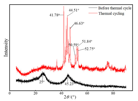
Figure 1.
XRD pattern of samples Ni/CF-0.21 and after induction heating.
2.4. Characterization
The microscopic morphology, composition, and properties of the electroless nickel-coated samples were characterized. The microscopic morphology of the samples before and after etching and the electroless plating samples was examined using scanning electron microscopy (SEM, S-4800, Tokyo, Japan). X-ray diffractometry (XRD, Bruker D8 advance, Karlsruhe, Germany) was used to measure the nickel diffraction peaks of the samples before and after induction heating. The hydrophobicity of the coatings with different deposition amounts was characterized using a static contact angle meter (HARKE-SPCAX1, Beijing Hako Testing Instrument Factory, Beijing, China). The adhesion of the coating to the CFRP substrate was evaluated using an adhesion tester (OU4000, Cangzhou Europol Testing Instrument Co., Cangzhou, China). An infrared thermal camera (RX-300, Bote (Lianyungang) Instrument Co., Lianyungang, China) and direct current power (ZXD2400, Beijing Hengtaixinlong Technology Co., Beijing, China) were used to detect the heating effect of the sample induction heating and electric heating. In the induction heating experiment, an electromagnetic sensor with an induction frequency of 150 kHz was used to generate an alternating eddy current. Meanwhile, the sample was placed on the coil of the induction heating experiment at a distance of 20 mm with a cycle of 300 s during induction heating.
3. Results and Discussion
3.1. Mechanism of Electroless Nickel Plating on CFRP
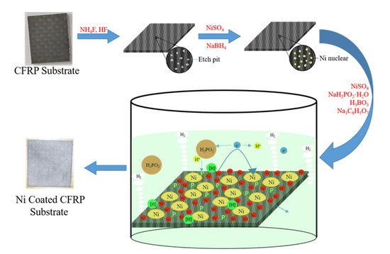
The fabrication process of nickel-coated CFRP material by electroless nickel plating is illustrated in Scheme 1. First, the clean CFRP substrate was immersed in the NH4 and HF solution to generate tiny pits on the surface, which decreased the formation energy of the nucleation reactant. Subsequently, the etched CFRP substrate was immersed in the NiSO4 and NaBH4 solution to produce the nucleation reactant in the etch pit. Borohydride ions (BH4−) possess strong reducibility to reduce Ni2+ to Ni0 (Reaction (1)) [38,39]. Etching pits can reduce the formation energy of the nucleation reactants. Ni2+ in the solution quickly moved to the active surface of the CFRP substrate after the start of electroless plating, and a large amount of Ni2+ was assembled on the active surface. The H2PO2− in the electroless nickel plating solution was attracted to the surface of Ni2+, generating HPO22− and a large amount of initial reduction [H] (Reaction (2)). The chemical nature of HPO22− is extremely unstable, and it easily reacts with water to form H2PO3−, H+, and free-moving e (Reaction (3)). The Ni2+ of the CFRP substrate surface contacts the ecological reduction [H], which is reduced to metallic nickel on the active surface and releases e (Reaction (4)). At the same time, other side reactions occur. H+ is converted to H2 via the free movement of electrons in the plating solution, which is the cause of small bubbles during the reaction (Reaction (5)). Finally, a layer of Ni plating is fabricated on the CFRP substrate using electroless nickel plating [40].
Scheme 1.
Deposition mechanism of electroless nickel plating on CFRP substrate.
3.2. Crystal Structure
By alternating the amount of nickel sulfate in the electroless nickel plating, we prepared Ni-coated CFRPs with different deposition Ni weights, named Ni/CF-0.08, Ni/CF-0.11, Ni/CF-0.14, Ni/CF-0.17, and Ni/CF-0.21, which contained 0.08, 0.11, 0.14, 0.17, and 0.21 g of Ni, respectively. Figure 1 shows the XRD pattern of the sample Ni/CF-0.21 before and after induction heating for 30 min. It can be seen from Figure 1 that the sample Ni/CF-0.21 just has two broad diffraction peaks at 2θ = 25° and 2θ = 45.23°, which proves that the nickel coating is amorphous [41]. After heating, the sample Ni/CF-0.21 has strong diffraction peaks at 2θ = 41.78°, 44.51°, 46.63°, 50.59°, 51.84°, and 52.75°. By comparing the PDF card, the diffraction peaks correspond to Ni5P2 (420) crystal phase, Ni (111) crystal phase, Ni3P (141) crystal phase, Ni3P (222) crystal phase, Ni3P (312) crystal phase, Ni (200) crystal phase, and Ni3P (312) crystal phase. Ni5P2 has the strongest diffraction peak [42]. The changes in peak diffraction demonstrate that the crystal structure changes from the original amorphous state to the polycrystalline state after induction heating. The high temperature generated by induction heating causes different degrees of recrystallization of the coating.
Figure 2 shows the XPS spectra of the sample Ni/CF-0.21 after induction heating. The XPS results show the presence of Ni, P, C, and O elements in the sample. The existence of the C element mainly arises from the CFRP substrate and the O element may mainly arise from the air. As shown in the high-resolution Ni 2p spectrum in Figure 2b, the peaks centered at 853.4 and 870.7 eV can be assigned to Ni species in Ni 2p nanohybrids. The peaks located at 856.6 and 874.6 eV accompanied by the two satellite peaks at 861.5 and 880.0 eV are attributed to the oxidized Ni species [43,44]. According to Figure 2c, the peaks centered at 130.3 eV in the P 2p spectrum can be ascribed to the low-valence P species in the Ni 2p nanohybrids [45]. At the same time, a peak at 134.2 eV can be assigned to the oxidized P species because of the exposure of the product in the air. For Figure 3d, peaks centered at 289, 287, and 286.3 eV can be ascribed to the epoxy resin in the CFRP substrate [46].
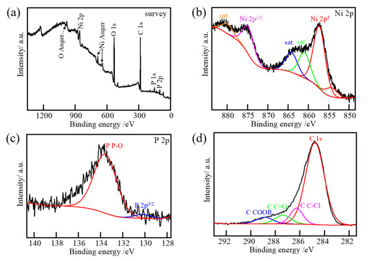
Figure 2.
XPS spectra of (a) survey, (b) Ni 2p, (c) P 2p, and (d) C 2p for sample Ni/CF-0.21 after induction heating.
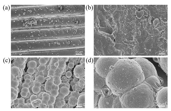
Figure 3.
Microscopic morphology of (a,b) CFRP and (c,d) Ni/CF-0.21.
3.3. Surface Morphology and Hydrophobic Property
The as-prepared Ni-CFRP exhibited a hierarchical microstructure characterized by scanning electron microscopy (SEM), as shown in Figure 3. The etching effect of the NH4 and HF solutions transformed the original smooth carbon fiber surface with an approximate diameter of 10 μm (Figure 3a) into rough morphology with a number of irregular tiny pits (Figure 3b), which can provide an extra driving force for crystal nucleation. From Figure 3c,d, it can be seen that the Ni particles with an approximate diameter of 8 μm were uniformly deposited on the carbon fiber surface [47], which endowed the Ni-coated CFRP with a tiered texture. The Ni content of the prepared coating layer influenced the wetting state of the textured surface. As shown in Figure 4, the water contact angles of CF (content of Ni is 0), Ni/CF-0.08, Ni/CF-0.08, Ni/CF-0.11, Ni/CF-0.14, Ni/CF-0.17, and Ni/CF-0.21 changes from 67.4°, 96.5°, 97.7°, 108.6°, 103.2°, and 102.6°, respectively. The clusters of cellular nickel particles with a hierarchical microstructure render the Ni-coated CFRP hydrophobic properties.
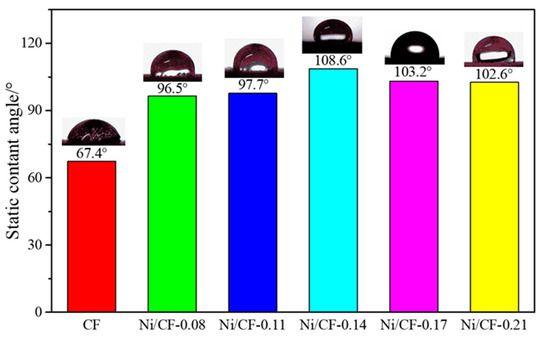
Figure 4.
Static contact angles of electroless Ni-CFRP with different Ni content.
The reason for the changes in the static contact angle is that a large number of clusters of cellular nickel particles are formed on the substrate surface, and the nickel layer on the surface of the coating is intact (as can be confirmed in Figure 3c,d). It is well known that almost super-hydrophobic surfaces are textured or rough. The clusters of cellular nickel particles uniformly distributed on the CFRP substrate result in good hydrophobicity. By comparing the static contact angles of the coatings with different Ni plating depositions, we can see that the static contact angle first increases with the increase in the content of nickel and then tends to be stable when the Ni plating deposition reaches 0.17 g because a stable surface structure forms when the deposition reaches a certain amount and the surface energy is substantially similar.
3.4. Adhesion
In order to evaluate the bonding strength between the as-prepared Ni coating and the substrate, we conducted a series of adhesion tests. The adhesion of the Ni-CFRP was tested using the Standard Scratch test of the paint and varnish paint films [48]. This standard divides the coatings with different adhesion strengths into six grades. The coating with grade 0 has the strongest adhesion strength. On the contrary, the coating with grade 5 has the worst adhesion strength. The standard stipulates that the grade is 0 when the scratch edge is smooth and the grade is 5 when there is a large amount of plating detached from the substrate and the peeling area is more than 65%. The test results show that the adhesion level of the Ni-CFRP surface except for the sample Ni/CF-0.08 is graded as 1, and the Ni/CF-0.14 and Ni/CF-0.21 samples are graded as 0, as shown in Figure 5, which indicates that the as-prepared Ni coating is tightly bonded to the substrate and not easily peeled off from the substrate. From Scheme 1 and the textured surface in Figure 3, it can be concluded that the strong adhesion of the Ni coating to the substrate can be attributed to the chemical etching process of the substrate. The substrate is chemically etched in the pretreatment, resulting in a large number of pits forming on the substrate. This process decreases the electroless nickel nucleation driving force, allowing the clusters of cellular nickel particles to be evenly distributed on the surface of the substrate.
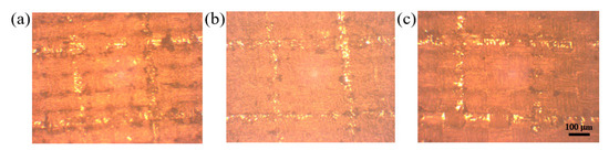
Figure 5.
Morphology of adhesion test of (a) Ni/CF-0.08, (b) Ni/CF-0.14, and (c) Ni/CF-0.21.
3.5. Electrical Conductivity
The surface resistances of Ni/CF-0.08, Ni/CF-0.11, Ni/CF-0.14, Ni/CF-0.17, and Ni/CF-0.21 are shown in Figure 6. Compared with the Ni/CF-0.08, the Ni/CF-0.21 coating quality is increased by 0.13 g, and the surface resistance decreases from 0.26 to 0.09 Ω·sq−1. The higher the number of nickel nanoparticles deposited on the CFRP substrate, the lower the surface resistance obtained, which is due to the increased degree of electron conduction between the nickel nanoparticles. In short, the introduction of electroless nickel plating plays an active role in improving the surface conductivity of CFRP.
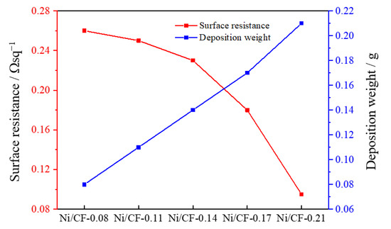
Figure 6.
The relationship of surface resistances and deposit weight of nickel with Ni/CF-0.08, Ni/CF-0.11, Ni/CF-0.14, Ni/CF-0.17, and Ni/CF-0.21.
3.6. Heating Performance
3.6.1. The Influence of Deposit Weight on Heating Efficiency
From the above results, we revealed that the deposition weight of Ni played an important role in the surface conductivity of CFRP. It is well known that the surface conductivity directly determines the heating performance of Ni-CFRP via the heating induction effect. The effect of the deposit weight on the induction heating efficiency under the circumstance of 30 V input voltage is shown in Figure 7. The highest equilibrium temperature of the samples with different deposition amounts in induction heating is shown in Figure 7a–e. The yellow rectangle represents the sample during induction heating, and the red circle represents the induction coil. The highest equilibrium temperatures of Ni/CF-0.08, Ni/CF-0.11, Ni/CF-0.14, Ni/CF-0.17, and Ni/CF-0.21 are 129, 150, 161, 173, and 185 °C, respectively. As illustrated in Figure 7f, the temperature rise rate of the Ni-CFRP increases with an increase inthe deposition of Ni, showing that the eddy current effect of the Ni-CFRP becomes more effective. This rule appears not only in the induction heating test but also in the electric heating test. The highest equilibrium temperatures of Ni/CF-0.08, Ni/CF-0.11, Ni/CF-0.14, Ni/CF-0.17, Ni/CF-0.21 are 55.5, 67, 72, 76, and 81 °C, respectively, under electric heating with 1.5 V input voltage.
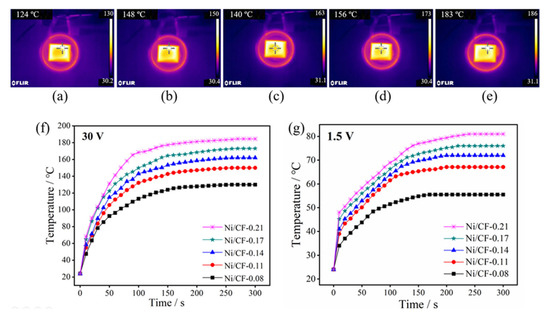
Figure 7.
Infrared images of the (a) Ni/CF-0.08, (b) Ni/CF-0.11, (c) Ni/CF-0.14, (d) Ni/CF-0.17, and (e) Ni/CF-0.21 under induction heating with 30 V, and the diagram of temperature/time curve of induction heating (f) and electric heating (g).
According to Faraday’s principle,
where ε is the electromotive force generated; n is the number of coil turns; ΔΦ is the amount of change in the magnetic flux, and Δt is the time it takes to change. It can be deduced from Equation (6) that the larger the number of coil turns, the larger the induced electromotive force generated by the Ni-CFRP. According to the Joule heat formula,
where P is the heating power; U is the input voltage; I is the input current, and R is the resistance. It is apparent that the higher the input voltage, the higher the heating power is. According to the heat conduction formula,
where qx is the heat dissipation power; k is the conductivity; ΔT is the temperature difference between the object and the environment, and x is the distance of heat transfer. The greater the temperature difference, the greater the heat dissipation power. It is assumed that the ambient temperature does not change during the heating process [49]. The heat dissipation power is 0 at the beginning. With ΔT increasing gradually after the start of heating, the heat dissipation power also gradually increases. Until qx = P, ΔT reaches the maximum value, that is, the heating element reaches the highest equilibrium temperature, so ΔT ∝ P [50]. According to Formulas (6)–(8), the highest equilibrium temperature of the Ni-CFRP surface induced by induction heating increases with an increase in the deposition.
In the induction heating test, the temperature-increasing rate of the Ni-CFRP is enhanced with an increase in the Ni deposition amount, which indicates that the eddy current effect of the Ni-CFRP is also significantly improved. The heating efficiency of Ni/CF-0.21 is the highest among the samples, and its equilibrium temperature is 184.5 °C. On the one hand, with an increase in nickel particle density, the magnetic permeability of the Ni-CFRP amplifies, so that the electromotive force of the coating in the alternating magnetic field increases, as shown in Formulas (6)–(8). On the other hand, the electrical conductivity of the Ni-CFRP increases with an increase in thickness, as a result of the conductive test. According to the infrared image, it also can be concluded that the heat distribution on the Ni-CFRP surface is uniform, indicating that the Ni coating on the CFRP surface is evenly distributed. In the electric heating test, as shown by Formulas (7) and (8), the rate of temperature increase changes with the coating deposition.
3.6.2. The Influence of Input Voltage on Induction Heating Efficiency
The effect of the input voltage on the induction heating efficiency of Ni/CF-0.21 is shown in Figure 8. The highest equilibrium temperatures of Ni/CF-0.21 with different input voltage in induction heating are displayed in Figure 8a–d. The highest equilibrium temperatures of Ni/CF-0.21 are 61.9, 87.9, 117, and 185 °C under induction heating with input voltages of 15, 20, 25, and 30 V, respectively. As shown in Figure 8e, the temperature-increasing rate of Ni/CF-0.21 increases with an increase in the input voltage. According to Formula 8, the greater the rate change of magnetic flux per unit of time, the greater the induced electromotive force. The rate of change of the magnetic flux through the sample or its induced electromotive force also changed when the input voltage was different. The DC voltage is usually 24 V on a modern passenger aircraft, which provides enough heat for deicing [51].
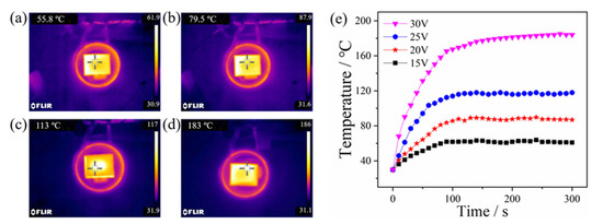
Figure 8.
Infrared images of Ni/CF-0.21 under induction heating with (a) 15 V, (b) 20 V, (c) 25 V, and (d) 30 V, and the diagram of temperature/time curve (e).
3.6.3. Repeatability
The induction heating stability of Ni/CF-0.21 is shown in Figure 9, with an input voltage of 30 V. It can be seen from Figure 9a,b that the maximum equilibrium temperature of Ni/CF-0.21 is 185 °C in the first induction heating cycle, and the equilibrium temperature increases to 205 °C in the second cycle. The Ni coating is crystallized at a high temperature during the first induction heating cycle, as shown in the XRD results, and the nickel particles in the coating are denser and more conducive. The reason why the temperature has partly changed in the second cycle is that heating causes diffusion of H2 from lattice defects of the Ni plating layer into the atmosphere. It can be seen from Figure 9c that the maximum equilibrium temperature of Ni/CF-0.21 always fluctuates in the range of 203–207 °C in the subsequent heating cycle, indicating that it has good heating stability.
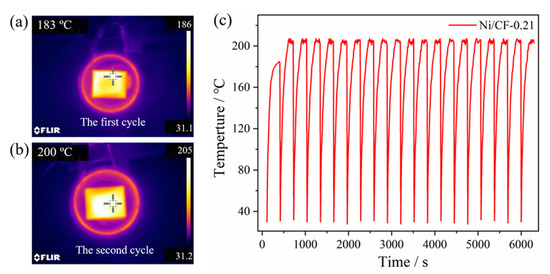
Figure 9.
Infrared images of Ni/CF-0.21 under induction heating with 30 V, the first cycle (a), the second cycle (b), and the diagram of temperature/time curve (c).
3.6.4. Effect of Ice Thickness on Melting Rate
The ice melting performance of Ni/CF-0.21 under induction heating was investigated. The infrared images of ice melting are shown in Figure 10. It takes 110 s to completely melt the ice with a thickness of 30 mm (the mass of ice is 33 g.). The melting process mainly occurs from 20 to 110 s during the entire induction heating. The process of ice melting is divided into two steps. In the first step, the heat generated by the sample is transferred to the adjacent area, and then the ice absorbs the heat and is melted into water. In the second step, the heat generated by the sample is transferred to the feed water that is around the ice block and then transferred from the water to the ice layer. In this step, melting ice of the same quality requires more heat because the specific heat capacity of water is larger than that of ice and the flowing water cannot fully transfer all heat to ice. Ice with a thickness of 30 mm has separated from the surface of Ni/CF-0.21 without external force after induction heating for only 80 s. This result proves the feasibility of the Ni/CF-0.21 for induction heating deicing.
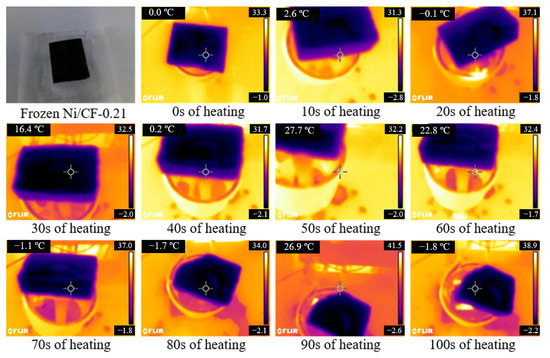
Figure 10.
The ice melting performance of Ni/CF-0.21 by induction heating.
4. Conclusions
A series of Ni coatings were deposited on the CFRP substrate by an electroless nickel plating process as a heater for aircraft deicing by induction heating. The Ni coatings are very strongly adhered to the CFRP substrate, the surface of Ni-CFRP showed hydrophobic properties, and the static contact angle of the water droplet increased by at least 50% after electroless nickel plating. The higher the amount of Ni plating on the CFRP substrate, the lower the surface resistance, and the lowest is 0.09 Ω·sq−1. The induction heating test shows that the maximum value of the Ni/CF-0.21 equilibrium temperature can reach 205 °C when the input voltage is 30 V. The high temperature generated by induction heating causes different degrees of recrystallization in the coating, which promotes the amorphous-microcrystalline-crystalline transformation. The reliability of the induction heating of sample Ni/CF-0.21 is verified by 20 cycles of induction heating experiments. The electric heating experiment shows that the maximum value of the sample Ni/CF-0.21 equilibrium temperature can reach 81 °C when the input voltage is 1.5 V. The sample Ni/CF-0.21 can melt an ice layer with a thickness of 30 mm in 110 s via induction heating. These results represent the excellent characteristics of Ni/CF-0.21, so that the crew can complete the deicing work based on these functions via the induction heating device on the ground or the pilots can achieve the deicing work via electrical heating during the flight. This provides a broad range of prospects in the field of aircraft deicing and transportation.
Author Contributions
Conceptualization, J.P. and W.Q.; writing—original draft preparation, M.Z. and W.Y.; writing—review and editing, W.Q. and Q.M. All authors have read and agreed to the published version of the manuscript.
Funding
This research was funded by the Fundamental Research Funds for the Central Universities grant number PHD2023-008.
Institutional Review Board Statement
Not applicable.
Informed Consent Statement
Not applicable.
Data Availability Statement
Not applicable.
Conflicts of Interest
The authors declare no conflict of interest.
References
- Greene, J. Guidebook for Selecting Methods to Monitor Airport and Aircraft Deicing Materials, 2nd ed.; Transportation Research Board of the National Academies: Washington, DC, USA, 2017. [Google Scholar]
- Tundis, A.; Ferretto, D.; Garro, A.; Brusa, E.; Muhlhauser, M. Dependability assessment of a deicing system through the RAMSAS method. In Proceedings of the 2017 IEEE International Symposium on Systems Engineering (Isse 2017), Vienna, Austria, 11–13 October 2017; pp. 106–113. [Google Scholar]
- Glover, E.N.K.; Bowen, C.R.; Gathercole, N.; Pountney, O.; Ball, M.; Spacie, C.; Seunarine, K. Graphene based skins on thermally responsive composites for deicing applications. Proc. SPIE 2017, 10165, 106–119. [Google Scholar] [CrossRef]
- De Pauw, D.; Dolatabadi, A. Effect of Superhydrophobic Coating on the Anti-Icing and Deicing of an Airfoil. J. Aircr. 2017, 54, 490–499. [Google Scholar] [CrossRef]
- Porter, D.J. Flight Failure: Investigating the Nuts and Bolts of Air Disasters and Aviation Safety; Rowman & Littlefield Publishing Group, Inc.: Lanham, MD, USA, 2020. [Google Scholar]
- Shen, X.; Wang, H.; Lin, G.; Bu, X.; Wen, D. Unsteady simulation of aircraft electro-thermal deicing process with temperature-based method. Proc. Inst. Mech. Eng. Part G J. Aerosp. Eng. 2019, 234, 388–400. [Google Scholar] [CrossRef]
- Sabatier, J.; Lanusse, P.; Feytout, B.; Gracia, S. Ice Accretion Detection and Anti-icing/Deicing Systems for Wind Turbine Blades; Lecture Notes in Electrical Engineering; Springer: Cham, Switzerland, 2020; Volume 495, pp. 641–663. [Google Scholar] [CrossRef]
- Xu, B.; Lu, F.; Song, G. Experimental Study on Anti-Icing and Deicing for Model Wind Turbine Blades with Continuous Carbon Fiber Sheets. J. Cold Reg. Eng. 2018, 32, 1. [Google Scholar] [CrossRef]
- Chavan, D.S.; Singh, A.; Sankpal, J.; Himanshu; Gaikwad, S.; Saahil, V.; Parashar, D.; Karandikar, P.B. Deicing of wind turbine blade by high frequency dielectric heating fabricating blade as a capacitor. In Proceedings of the 2017 IEEE International Conference on Circuit, Power and Computing Technologies (Iccpct), Kollam, India, 20–21 April 2017. [Google Scholar]
- Zhang, Z.; Shen, X.; Lin, G.; Yuan, Q.; Tian, S. Dynamic response analysis of multi-excitation structure of electro-impulse deicing system. In Proceedings of the 2016 Ieee/Csaa International Conference on Aircraft Utility Systems (Aus), Beijing, China, 10–12 October 2016; pp. 955–960. [Google Scholar] [CrossRef]
- Wu, T.; Sun, M.; Huang, B. Strain modulation of phase transformation of noble metal nanomaterials. Infomat 2020, 2, 715–734. [Google Scholar] [CrossRef]
- Shi, Y.; Jia, Y. Multimodal Shear Wave Deicing Using Fibre Piezoelectric Actuator on Composite for Aircraft Wings. IEEE/ASME Trans. Mechatron. 2018, 23, 2090–2098. [Google Scholar] [CrossRef]
- Ma, L.W.; Wang, J.K.; Zhao, F.T.; Wu, D.Q.; Huan, Y.; Zhang, D.W.; Zhang, Z.J.; Fu, W.Y.; Li, X.G.; Fan, Y. Plasmon-mediated photothermal and superhydrophobic TiN-PTFE film for anti-icing/deicing applications. Compos. Sci. Technol. 2019, 181, 107696. [Google Scholar]
- Gavrichkova, O.; Hajiaghayeva, R.A.; Liberati, D.; Pallozzi, E.; Calfapietra, C.; Vasenev, V. Effects of the Road Deicing Practices on Gas Exchange Parameters in Urban Lawn Ecosystems; Spring: Berlin/Heidelberg, Germany, 2020; pp. 45–51. [Google Scholar] [CrossRef]
- Dan, H.-C.; Tan, J.-W.; Du, Y.-F.; Cai, J.-M. Simulation and optimization of road deicing salt usage based on Water-Ice-Salt Model. Cold Reg. Sci. Technol. 2020, 169, 102917. [Google Scholar] [CrossRef]
- Yuan, J.; Du, Z.; Wu, Y.; Xiao, F. Freezing-thawing resistance evaluations of concrete pavements with deicing salts based on various surfaces and air void parameters. Constr. Build. Mater. 2019, 204, 317–326. [Google Scholar] [CrossRef]
- Xie, T.; Dong, J.; Chen, H.; Jiang, Y.; Yao, Y. Experimental investigation of deicing characteristics using hot air as heat source. Appl. Therm. Eng. 2016, 107, 681–688. [Google Scholar] [CrossRef]
- Jiang, G.; Chen, L.; Zhang, S.; Huang, H.-X. Superhydrophobic SiC/CNTs Coatings with Photothermal Deicing and Passive Anti-Icing Properties. ACS Appl. Mater. Interfaces 2018, 10, 36505–36511. [Google Scholar] [CrossRef] [PubMed]
- Liu, Z.Y.; Mu, Z.; Wang, J.K.; Chang, Z.; Liu, J. Design and Parameter Analysis of Laser Deicing Optical System. Acta Photonica Sin. 2018, 47, 0822001. [Google Scholar]
- Eden, P.E. The World’s Most Powerful Civilian Aircraft; Rosen Publishing: New York, NY, USA, 2017. [Google Scholar]
- United States Congress House. Committee on Transportation and Infrastructure. Subcommittee on Aviation, Lessons Learned from the Boeing 787 Incidents: Hearing before the Subcommittee on Aviation of the Committee on Transportation and Infrastructure, House of Representatives, one Hundred Thirteenth Congress, First Session, June 12, 2013; U.S. Government Printing Office for Sale by the Superintendent of Documents: Washington, DC, USA, 2013.
- Liu, T.; Li, Y. Addressing the Achilles’ heel of pseudocapacitive materials: Long-term stability. InfoMat 2020, 2, 807–842. [Google Scholar] [CrossRef]
- Ke, G.; Duan, C.; Huang, F.; Guo, X. Electrical and spin switches in single-molecule junctions. InfoMat 2019, 2, 92–112. [Google Scholar] [CrossRef]
- Thiel, C.; Gehlen, C.; Foestl, F. Service life prediction of concrete under freeze-thaw deicing salt attack with intermittent dry periods. In Life-Cycle Analysis and Assessment in Civil Engineering: Towards an Integrated Vision; CRC Press: Boca Raton, FL, USA, 2019; pp. 521–528. [Google Scholar]
- Wu, J.; Li, H.; Lai, X.; Chen, Z.; Zeng, X. Superhydrophobic Polydimethylsiloxane@Multiwalled Carbon Nanotubes Membrane for Effective Water-in-Oil Emulsions Separation and Quick Deicing. Ind. Eng. Chem. Res. 2019, 58, 8791–8799. [Google Scholar] [CrossRef]
- Tarfaoui, M.; El Moumen, A.; Boehle, M.; Shah, O.; Lafdi, K. Self-heating and deicing epoxy/glass fiber based carbon nanotubes buckypaper composite. J. Mater. Sci. 2019, 54, 1351–1362. [Google Scholar] [CrossRef]
- Chu, Z.M.; Jiao, W.C.; Huang, Y.F.; Ding, G.M.; Zhong, X.; Yan, M.L.; Zheng, Y.T.; Wang, R.G. FDTS-Modified SiO2/rGO Wrinkled Films with a Micro-Nanoscale Hierarchical Structure and Anti-Icing/Deicing Properties under Condensation Condition. Adv. Mater. Interfaces 2019, 7, 1901446. [Google Scholar] [CrossRef]
- Redondo, O.; Prolongo, S.G.; Campo, M.; Sbarufatti, C.; Giglio, M. Anti-icing and de-icing coatings based Joule’s heating of graphene nanoplatelets. Compos. Sci. Technol. 2018, 164, 65–73. [Google Scholar] [CrossRef]
- Jang, S.-H.; Park, Y.-L. Carbon nanotube-reinforced smart composites for sensing freezing temperature and deicing by self-heating. Nanomater. Nanotechnol. 2018, 8, 1847980418776473. [Google Scholar] [CrossRef]
- Jiang, H.; Wang, H.; Liu, G.; Su, Z.; Wu, J.; Liu, J.; Zhang, X.; Chen, Y.; Zhou, W. Light-weight, flexible, low-voltage electro-thermal film using graphite nanoplatelets for wearable/smart electronics and deicing devices. J. Alloys Compd. 2017, 699, 1049–1056. [Google Scholar] [CrossRef]
- Choi, B.-K.; Park, S.-J.; Seo, M.-K. Effect of Processing Parameters on the Thermal and Electrical Properties of Electroless Nickel-Phosphorus Plated Carbon Fiber Heating Elements. C-J Carbon Res. 2020, 6, 6. [Google Scholar] [CrossRef]
- Jeong, H.; Lee, C.-J.; Myung, W.-R.; Min, K.D.; Jung, S.-B. Effects of Temperature–Humidity Treatment on Bending Reliability of Epoxy Sn–58Bi Solder with Electroless Nickel Immersion Gold (ENIG) and Electroless Nickel Electroless Palladium Immersion Gold (ENEPIG) Surface Finishes. Sci. Adv. Mater. 2020, 12, 564–570. [Google Scholar] [CrossRef]
- Moazzenchi, B.; Montazer, M. Click Electroless Plating and Sonoplating of Polyester with Copper Nanoparticles Producing Conductive Fabric. Fibers Polym. 2020, 21, 522–531. [Google Scholar] [CrossRef]
- Moazzenchi, B.; Montazer, M. Click electroless plating of nickel nanoparticles on polyester fabric: Electrical conductivity, magnetic and EMI shielding properties. Colloids Surf. A 2019, 571, 110–124. [Google Scholar] [CrossRef]
- Peng, L.; Guo, R.; Lan, J.; Jiang, S. Fabrication and Characterization of Photochromic Spirooxazine/Polyvinylidene Fluoride Fiber Membranes via Electrospinning. Fibres Text. East. Eur. 2018, 26, 34–38. [Google Scholar] [CrossRef]
- Guo, R.; Jing, X.; Peng, L.; Lan, J.; Jiang, S.; Yan, W. Nickel-catalyzed deposition of Cu film on PET fabric with supercritical fluid. J. Mater. Sci. Mater. Electron. 2017, 28, 16618–16626. [Google Scholar] [CrossRef]
- Peng, L.; Guo, R.; Lan, J.; Jiang, S.; Zhang, Z.; Xu, J. Preparation and characterization of copper-coated polyester fabric pretreated with laser by magnetron sputtering. J. Ind. Text. 2018, 48, 482–493. [Google Scholar] [CrossRef]
- Shang, W.; Zhan, X.; Wen, Y.; Li, Y.; Zhang, Z.; Wu, F.; Wang, C. Deposition mechanism of electroless nickel plating of composite coatings on magnesium alloy. Chem. Eng. Sci. 2019, 207, 1299–1308. [Google Scholar] [CrossRef]
- Hu, R.; Su, Y.; Liu, H. Deposition behaviour of nickel phosphorus coating on magnesium alloy in a weak corrosive electroless nickel plating bath. J. Alloys Compd. 2016, 658, 555–560. [Google Scholar] [CrossRef]
- Liu, C.; Li, X.; Li, X.; Xu, T.; Song, C.; Ogino, K.; Gu, Z. Preparation of Conductive Polyester Fibers Using Continuous Two-Step Plating Silver. Materials 2018, 11, 2033. [Google Scholar] [CrossRef]
- Kang, J.-S.; Lee, Y.-S.; Lee, J.-H. Effects of Bath Composition and P Contents on the Defects of NiP Layer in Electroless Nickel Immersion Gold Process. J. Nanosci. Nanotechnol. 2019, 19, 4287–4291. [Google Scholar] [CrossRef]
- Rao, L.; Tang, J.; Hu, S.; Shen, L.; Xu, Y.; Li, R.; Lin, H. Inkjet printing assisted electroless Ni plating to fabricate nickel coated polypropylene membrane with improved performance. J. Colloid Interface Sci. 2020, 565, 546–554. [Google Scholar] [CrossRef] [PubMed]
- Gill, T.M.; Zhao, J.; Berenschot, E.J.W.; Tas, N.; Zheng, X. Conformal Electroless Nickel Plating on Silicon Wafers, Convex and Concave Pyramids, and Ultralong Nanowires. ACS Appl. Mater. Interfaces 2018, 10, 22834–22840. [Google Scholar] [CrossRef]
- Hsieh, S.H.; Hsieh, J.M.; Chen, W.J.; Chuang, C.C. Electroless Nickel Deposition for Front Side Metallization of Silicon Solar Cells. Materials 2017, 10, 942. [Google Scholar] [CrossRef] [PubMed]
- Agarwal, A.; Pujari, M.; Uppaluri, R.; Verma, A. Efficacy of reducing agent and surfactant contacting pattern on the performance characteristics of nickel electroless plating baths coupled with and without ultrasound. Ultrason. Sonochem. 2014, 21, 1382–1391. [Google Scholar] [CrossRef] [PubMed]
- Bonin, L.; Bains, N.; Vitry, V.; Cobley, A. Electroless deposition of nickel-boron coatings using low frequency ultrasonic agitation: Effect of ultrasonic frequency on the coatings. Ultrasonics 2017, 77, 61–68. [Google Scholar] [CrossRef]
- Popescu, S.M.; Barlow, A.J.; Ramadan, S.; Ganti, S.; Ghosh, B.; Hedley, J. Electroless Nickel Deposition: An Alternative for Graphene Contacting. ACS Appl. Mater. Interfaces 2016, 8, 31359–31367. [Google Scholar] [CrossRef] [PubMed]
- GB/T 9286-1998; Paints and Varnishes—Cross Cut Test for films. National Quality and Technology Supervision Bureau: Beijing, China, 1998.
- Yoshikawa, R.; Tenjimbayashi, M.; Matsubayashi, T.; Manabe, K.; Magagnin, L.; Monnai, Y.; Shiratori, S. Designing a Flexible and Transparent Ultrarapid Electrothermogenic Film Based on Thermal Loss Suppression Effect: A Self-Fused Cu/Ni Composite Junctionless Nanonetwork for Effective Deicing Heater. ACS Appl. Nano Mater. 2018, 1, 860–868. [Google Scholar] [CrossRef]
- Kim, G.; Lim, J.W.; Yeon, C.; Kim, T.; Lee, H.C.; Yun, S.J. Effective deicing of vehicle windows and thermal response of asymmetric multilayered transparent-film heaters. J. Alloys Compd. 2019, 774, 1092–1101. [Google Scholar] [CrossRef]
- Chen, B.; Gao, D.; Wang, L. Research of Multi-Information Integration for the Aircraft Ground Centralized Deicing Monitoring System Based on Wireless Data Transmission. IEEE Access 2018, 6, 52460–52470. [Google Scholar] [CrossRef]
Disclaimer/Publisher’s Note: The statements, opinions and data contained in all publications are solely those of the individual author(s) and contributor(s) and not of MDPI and/or the editor(s). MDPI and/or the editor(s) disclaim responsibility for any injury to people or property resulting from any ideas, methods, instructions or products referred to in the content. |
© 2023 by the authors. Licensee MDPI, Basel, Switzerland. This article is an open access article distributed under the terms and conditions of the Creative Commons Attribution (CC BY) license (https://creativecommons.org/licenses/by/4.0/).