Article

The Effects of High-Energy Composite Surface Layer Modification on the Impact Performance of the H13 Steel Cutter Ring for Shield Tunneling Machine

College of Marine Equipment and Mechanical Engineering, Jimei University, Xiamen 361000, China
*
Authors to whom correspondence should be addressed.
Coatings 2023, 13(9), 1482; https://doi.org/10.3390/coatings13091482
Submission received: 13 July 2023 / Revised: 4 August 2023 / Accepted: 14 August 2023 / Published: 22 August 2023

Abstract

:
The service life of the cutter ring of the shield tunneling machine affects the efficiency and cost of its tunneling. However, traditional heat treatment processes cannot simultaneously optimize both impact toughness and surface hardness, often leading to cracks or excessive wear of the cutter ring, greatly reducing their service life. According to the above situation, this paper applies high-energy composite modification treatment to H13 steel samples commonly used for the cutter ring of the hob and analyzes the impact toughness, hardness, microstructure, residual stress, and morphology characteristics of fracture of the samples under different high-energy composite modification processes. The study also investigates the effects of high-energy composite modification processes on the hardness and impact toughness of the samples. The experimental results show that the high-energy composite modification process enables the specimens to have good impact toughness and surface hardness simultaneously. The H13 steel sample has the best performance after carburizing, quenching, and laser shock modification, with a maximum surface hardness of 1017.5HV0.2 and an impact toughness of 15.64 J/cm2. Laser shock modification improves the surface residual compressive stress and hardness of H13 steel samples and also improves their impact toughness.

1. Introduction

The shield tunneling machine plays an indispensable role in the development and utilization of underground space as specialized equipment for tunneling. The working environment during tunneling of the shield tunneling machine is harsh. High-quartz content rock strata, clay rock layers, and fractured loose rock strata are often encountered [1]. The cutter ring of the hob endures complex loads such as huge impact, friction, and high-pressure stress during tunneling using the shield tunneling machine [2]. Its main forms of failure include cracking, wear, and edge curling [3,4]. The crack caused by the insufficient impact toughness of the cutter ring greatly reduces its service life [5]. The cutter ring of the hob is a key component of the shield tunneling machine. It incurs the highest maintenance costs. Therefore, the R&D of a high-performance cutter ring for the hob of the shield tunneling machine with a long service life is of great significance for reducing construction costs and improving construction efficiency [3].
Currently, the main material of the shield tunneling machine’s cutter ring is H13 steel (4Cr5MoSiV1 with a C content of 0.41%), which has high toughness, hardenability, and cold and hot fatigue resistance and does not easily develop thermal fatigue cracks [6]. Ren et al. [7] analyzed defects such as fracture, eccentric wear, and wear of tools made of H13 steel. Jagota V et al. [8] found that H13 die steel had fine grains and high toughness when austenitized at 1000 °C, and the impact toughness decreased with the increase in austenitizing temperature. Zhu et al. [9] studied the effects of tempering temperature and time on the impact toughness of H13 steel and concluded that the impact toughness was the best after pre-tempering at 640 °C for 10 min and tempering at 600 °C for 30 min. Peng et al. [10] discovered that during low-temperature nitriding of H13 steel at 470 °C, a nitriding layer with only a diffusion zone was formed on the surface, greatly improving its thermal fatigue resistance and impact toughness. The rupture and peeling of the compound layer on the outermost surface (white bright layer) did not induce premature failure. In summary, most current researchers have studied the effects of specific process parameters on the hardness and impact toughness of H13 steel from the perspective of transition hardening and have achieved certain results.
It is difficult to match the hardness and impact toughness of the cutter ring of the hob of the shield tunneling machine. Most scholars use heat treatment and other methods to improve the wear resistance of the hob by increasing its hardness. However, it diminishes the hob’s impact resistance. It cannot endure a high impact load. Finally, due to insufficient hob toughness, the cutter ring cracks and fractures. In response to these issues, researchers have discovered that developing a cutter ring with a gradient structure that is hard on the outside and tough on the inside is one of the effective ways to increase the service life of the hob.
Currently, researchers mainly develop the hardness gradient structure through heat treatment or strain hardening, giving the materials high impact toughness and wear resistance. Wang et al. [11] quenched, tempered, and nitrided H13 steel to coarsen the precipitated Cr23C6 phase, thus reducing hardness and improving the impact toughness of the sample. At the same time, the samples exhibited good wear resistance under light loads. Lee et al. [12] discovered that surface refinement was generated by microstructure deformation through continuous processing of metal sheets with single-roll angular rolling and ultrasonic nanocrystalline surface processing, and the gradient structure after processing had excellent strength and toughness. Fu et al. [13] performed abrasive water jet shot blasting and ultrasonic impact treatment on AISI 4340 steel to build a gradient structure. This approach maintained high impact toughness while improving the surface hardness and wear resistance of the sample. Zou et al. [14] built a nanometer crystalline grain field on the surface of the 40CrNiMoA steel sample through ultrasonic rolling, allowing the test sample to have a good residual compressive stress and gradient structure of hardness, retain high impact toughness, and increase its wear life.
In summary, this paper discusses how the wear resistance and impact resistance of materials can be improved by building a gradient structure. However, transition hardening and strain hardening are not combined to build the high-performance gradient structure. The innovation of this article is to use carburizing, nitriding, heat treatment, and laser modification for high-energy composite modification on H13 steel to build a smooth gradient structure. At the same time, the Charpy impact test was used to evaluate the impact toughness of H13 steel samples subjected to different process treatments. The effects of high-energy composite modification processes on its impact toughness were systematically analyzed, and the high-energy composite modification process was optimized to give the samples high impact resistance and hardness.

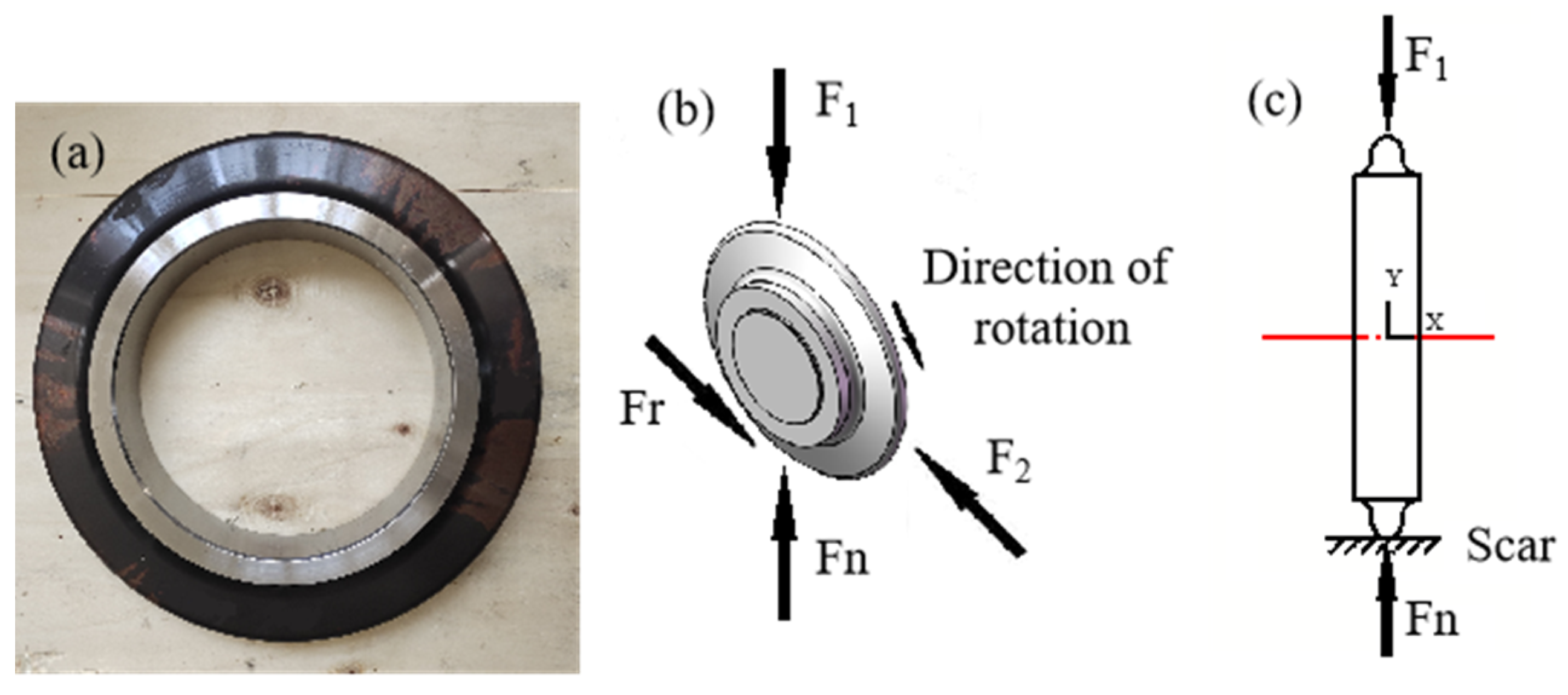
2. Analysis on the Service Status of the Cutter Ring

The hob applies force to the rock in three directions during rock breaking. These forces include the normal thrust provided by the thrust of the cutterhead, the tangential rolling force provided by the cutterhead rotation, and the lateral force produced by the centrifugal effect of the hob squeezing the rock and the cutterhead rotation [15]. Relatively, the rock produces counter-forces in three dimensions on the hob, as shown in Figure 1, in which Fr is the resistance in the direction of rolling of the hob, Fl is the counter-force of lateral pressure, and Fn is the normal counter-force. The hob’s cutter ring can break easily under the impact load due to the abrupt variations in the rock formation’s nature when it is in a non-uniform rock formation, greatly affecting the service life of the material [16].

3. Materials and Methods

The high-energy composite modified surface layer structure constructed on the surface layer of the test sample in this paper [17] is shown in Figure 2. The surface layer of the test sample is strengthened by phase transformation through carburizing and nitriding surface chemical heat treatment, resulting in a high-hardness martensitic structure in the surface layer while maintaining a tempered martensitic structure in the core, thereby endowing the core of the test sample with excellent impact toughness and the surface layer with high hardness and strength. Based on this, laser shock modification technology was used for strain hardening of the material on the surface layer, further improving the hardness and strength of the surface layer and obtaining a gradient field of ultra-high hardness, an ultra-high residual compressive stress field, and an ultra-fine grain field. In practical scenarios, the appropriate high-energy composite modification process should be selected according to service conditions and materials to construct the high-energy composite modified layer.

3.1. The Cutter Ring Material

The chemical composition of H13 steel used for hobs of the shield tunneling machine is shown in Table 1 (data measured by direct reading spark spectrometer SpectroMAXx BT), and the critical transition temperature is shown in Table 2 (data provided by material supplier). The commonly used quenching temperature of H13 steel is 1000–1050 °C, and the structure after quenching is acicular Martensite. Generally, H13 steel should be tempered twice or more at 530–650 °C after quenching. After tempering, H13 steel is composed of tempered Martensite and carbide with a hardness of approximately 56HRC. With high toughness and strength [11], the cutter ring of the hob can withstand high stress and severe impact in harsh working conditions.

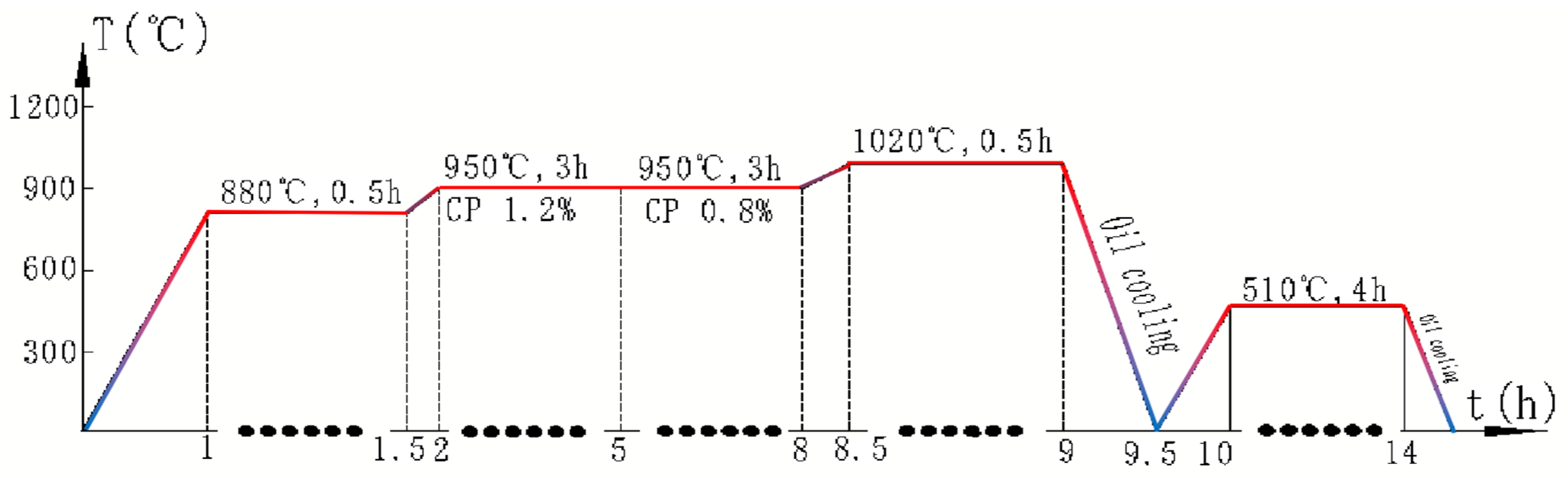
3.2. Heat Treatment Process of Material of Cutter Ring

To investigate the effect of the surface hardening process on the impact toughness of the sample, H13 steel samples were carburized. Its process is shown in Figure 3. The H13 steel sample was carburized and quenched using an HZCT2-65 double-chamber vacuum gas-cooled oil quenching carburizing furnace. First, the strong carburizing time was 3 h at a carbon potential of 1.2% and a temperature of 950 °C; then, the diffuse carburization was conducted for 3 h at a carbon potential of 0.8%; finally, the temperature was raised to 1020 °C and maintained for 0.5 h before oil cooling. After carburizing and quenching, the sample was placed in an HZR-20 air circulation tempering furnace for tempering treatment. First, it was heated to 510 °C. Then, the temperature was maintained for 4 h, to ensure the complete transformation of the quenched, unstable martensite. The sample was nitrided with an LDNBMC-F ion nitriding furnace. In a gas atmosphere of N2:H2 = 450 mL/min:150 mL/min, at an air pressure of 300 Pa, and a temperature of 480 °C, the temperature was kept for 8 h and finally cooled with the furnace (Figure 4).

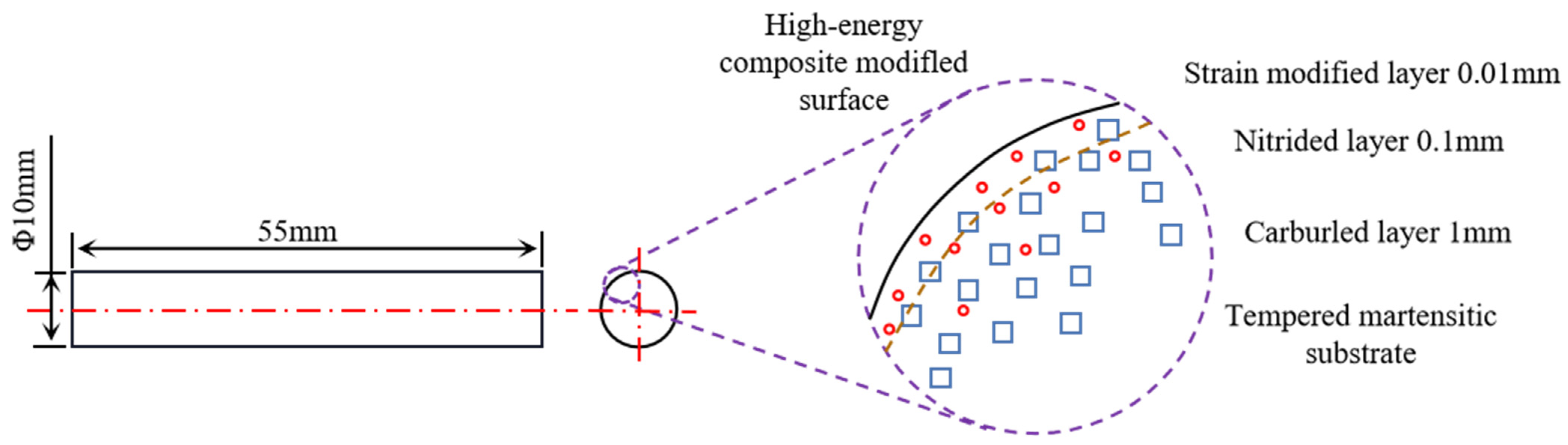
3.3. High-Energy Surface Layer Modification of the Hob Material

In this study, laser shock modification technology was used for strain hardening of H13 steel samples, and laser shock hardening was performed on the LAMBER-12 surface laser modification equipment [18]. The process parameters are shown in Table 3. To study the effects of the high-energy composite surface layer modification process on the impact resistance of H13 steel samples, seven different process schemes were designed (Figure 5), as shown in Table 4. No.1 is the sample with high hardness obtained through low-temperature tempering, No.2 is the carburized sample, No.3 is the nitrided sample, No.4 is the carburized and nitrided sample, No.5 is the carburized and nitrided laser shock sample, No.6 is the carburized laser shock sample, and No.7 is the nitrided laser shock sample.

4. Results

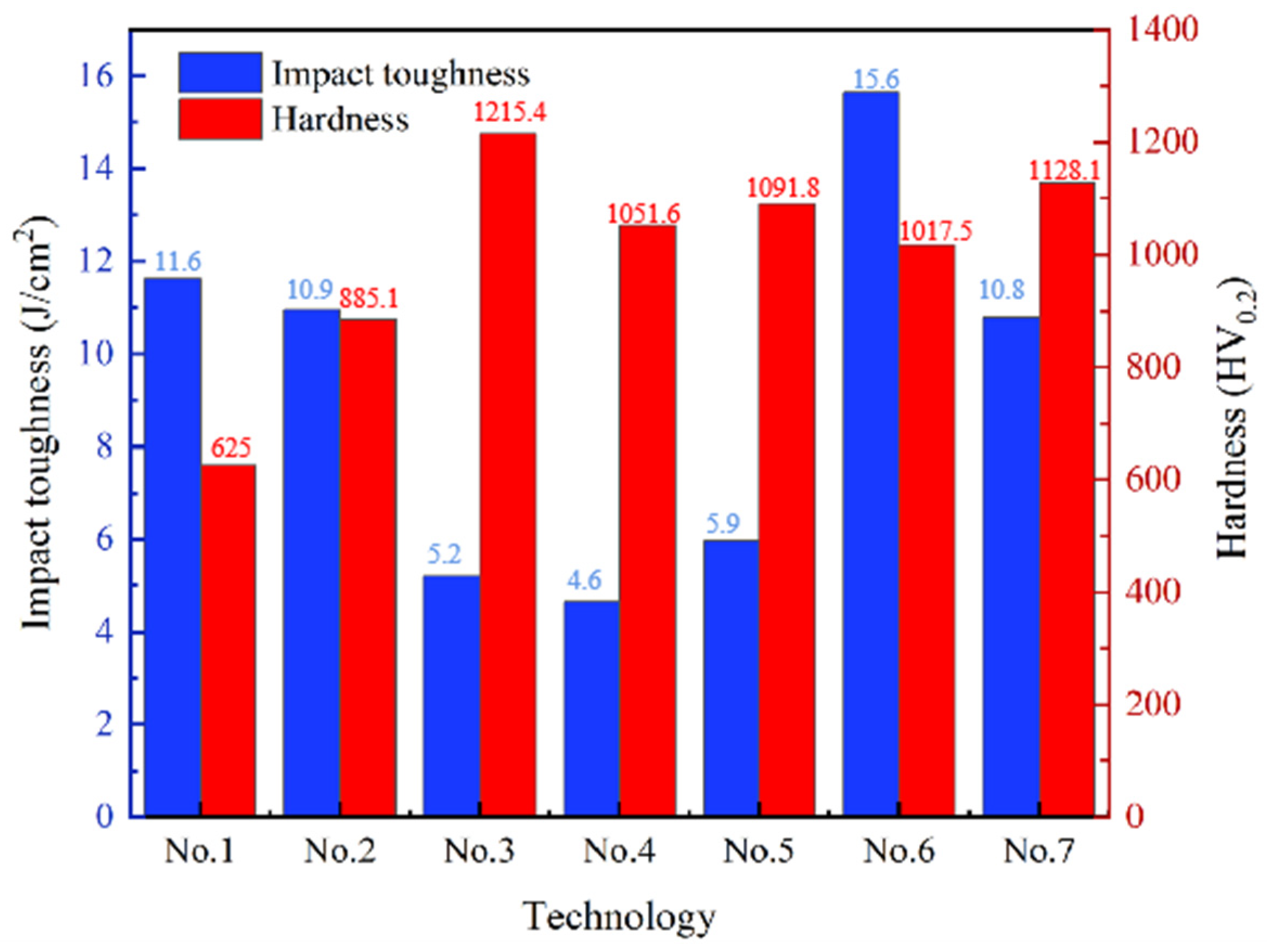
4.1. Impact Toughness and Hardness

The impact toughness of material can be measured through the Charpy impact experiment (GB/T 229—2020), where the test sample is generally processed into a square prism with notches. In this study, modifications were made to the shape of the sample based on the Charpy impact experiment and uses a Φ10 × 55 mm round rod (Figure 3) for the experiment on the ZBC230 Charpy test machine. The impact toughness value áK is one of the comprehensive performance indicators reflecting the material’s resistance to impact load. Its calculation formula [19] is as follows:
áK = AK/S0
in which, AK is the impact absorbing energy of the sample (J) and S0 is the cross-sectional area of the sample (cm2).
Figure 6 shows the impact toughness value áK of an H13 steel round rod sample under different process conditions. From the experiment results, it can be seen that the process conditions have a significant effect on the impact toughness value of the H13 steel sample. The CQTL sample (No.6) has the highest impact toughness, which is up to 15.64 J/cm2, while the CQTN sample (No.4) has the lowest impact toughness. QT sample (No.1), CQT sample (No.2), CQTL sample (No.6), and QTNL sample (No.7) have higher impact toughness. After laser hardening, the impact toughness values of the CQTNL sample (No.5), CQTL sample (No.6), and QTNL sample (No.7) increased by 20.16%, 42.57%, and 107.5%, respectively, compared to the CQTN sample (No.4), CQT sample (No.2), and QTN sample (No.3) without laser hardening. This indicates that laser shock can improve the impact toughness of the material.
The microhardness of the sample along the cross-sectional direction was measured using the Falcon 500 Vickers microhardness tester, with a measurement load of 200 g and a loading time of 10 s. Figure 7 shows the distribution of hardness on the cross section of the sample. From it, it can be seen that the hardness of QT sample No.1 is uniformly distributed. The surface layer hardness of nitrided samples No.3, No.4, No.5, and No.7 is relatively high. The maximum hardness is 1215.4HV0.2, 1051.6HV0.2, 1091.8HV0.2, and 1128.1HV0.2, respectively. Additionally, the hardness of samples No.3, No.4, No.5, and No.7 nitrided QTN samples and QTNL sample sharply reduced when the nitriding layer did not exceed 100 mm but the depth exceeded 90 mm. Among them, the hardness of No.4 and No.5 samples at 0.3 mm was lower than that of the carburized No.2 and No.6 samples due to the diffusion of carbon elements during nitriding, but the hardness was higher after 1 mm was exceeded. Compared with nitrided samples, the hardness distribution of carburized samples No.2 and No.6 was gentle, and the maximum hardness of the CQTL sample after laser shock (No.6) could reach 1017.5HV0.2. This indicates that H13 steel of No.6 has the best hardness, impact toughness, and comprehensive properties. When the depth exceeds 1 mm, the carbon content of the No.2–No.7 sample is approximately equal to the carbon content of the matrix, and the hardness is about 550HV0.2.

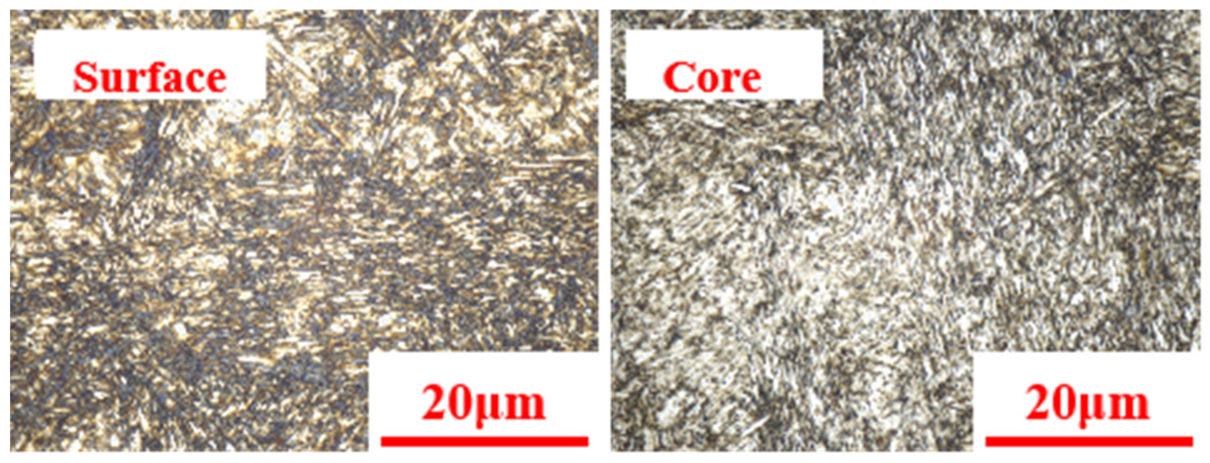
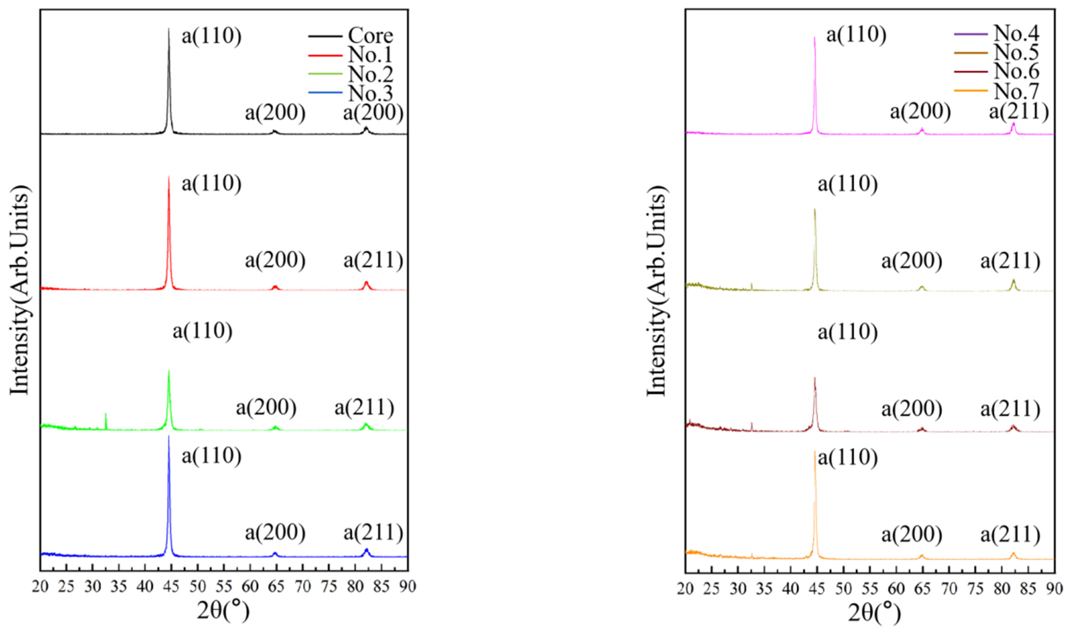
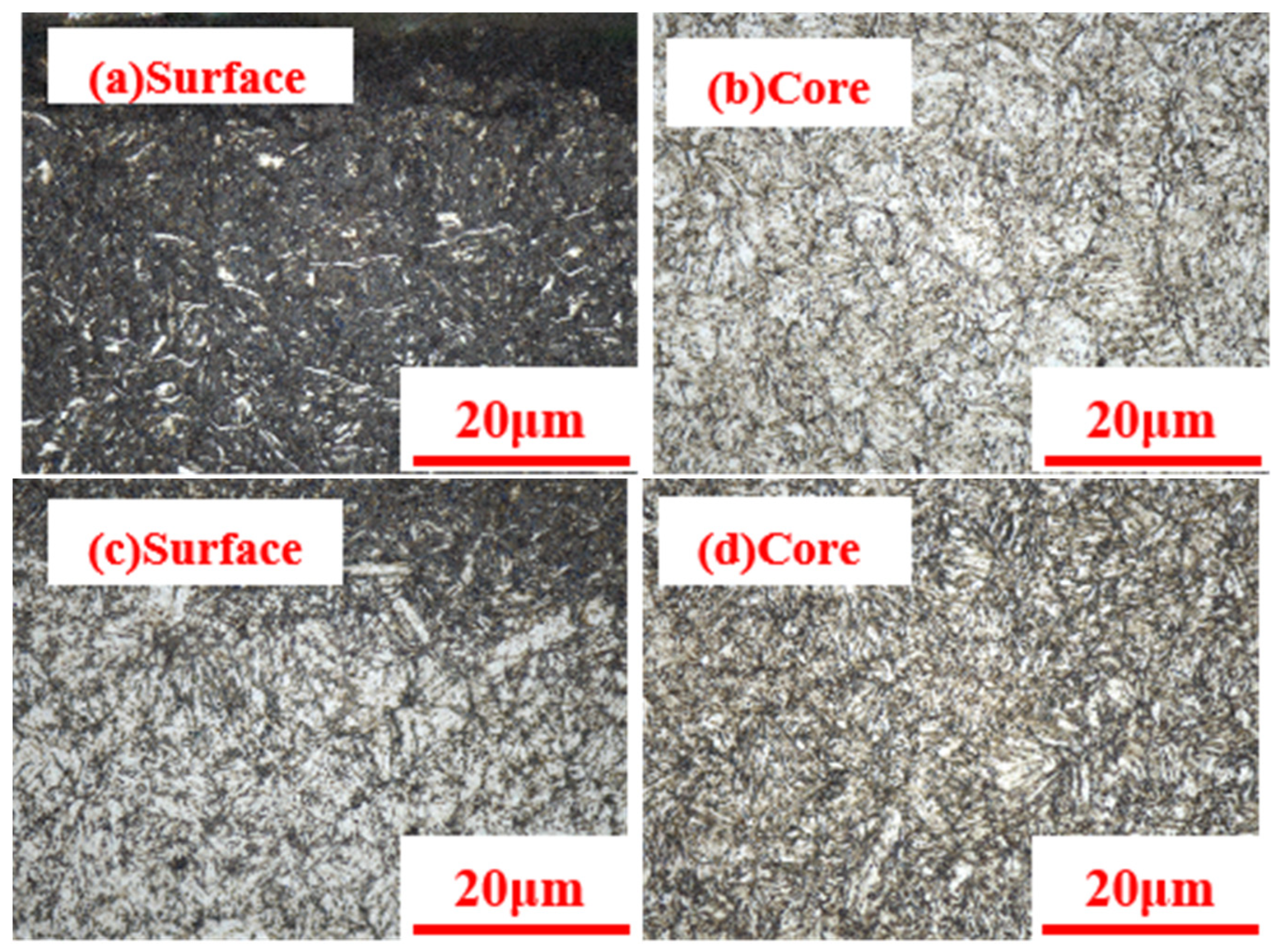
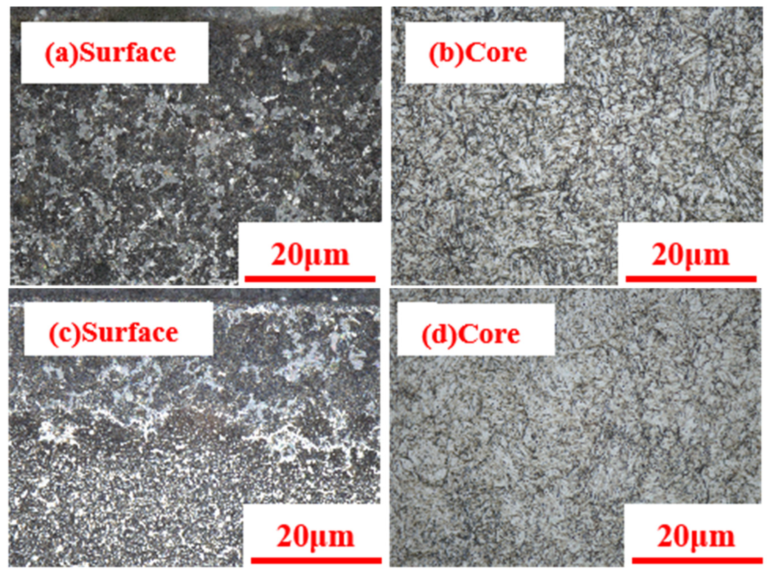
4.2. Microstructure Analysis

Samples made with different processes were ground and polished. A 5% nital solution with different concentrations was used to corrode them. The metallographic structures of different sample sections were observed using a VK-X1000k3D laser scanning confocal microscope. The residual stress on the surface of the sample was measured by HDS-I X-ray stress tester, and the scanning speed was set to 0.1 °/s. The metallographic structures of the quenched and low-temperature-tempered QT sample are shown in Figure 8. It can be observed that the surface layer and core structure both have the shape of fine needles. According to the X-ray diffraction pattern (Figure 9), the surface layer and core of the QT sample are mainly composed of α phase. Therefore, we can know that the microstructure of the QT sample is needle-shaped tempered Martensite [20].
The microstructure of the carburized CQT sample is shown in Figure 10. It can be observed that the surface layer structure has the shape of fine needles. According to the X-ray diffraction pattern (Figure 9), the main phase is α phase. We can tell that the sample’s surface layer is acicular tempered Martensite [20], its maximum hardness is 885.14HV0.2, while the hardness in the core is lower, the microstructure is tempered acicular Martensite, and its impact toughness is relatively good. After laser shock modification, the surface layer structure of the CQTL sample (Figure 10c) became denser, and the residual compressive stress on the surface of the sample increased [21] (as shown in Figure 11). The hardness of the sample increased (Figure 7). At the same time, the residual compressive stress increased, leading to an increase in the impact toughness of the CQTL sample [22].
According to the X-ray diffraction pattern (Figure 9), the main phase in the nitrided QTN sample is α phase, but vein-like nitrides can be observed in the microstructure of the surface layer (Figure 12) [23]. Nitride has high hardness and brittleness, which increases the surface hardness of the sample. However, vein-like nitrides disrupt the continuity of the matrix, making the sample prone to cracking under impact load [24], thereby reducing its impact toughness (Figure 6). The vein-like nitrides on the surface layer of the QTNL sample after laser shock modification were refined [21] (Figure 12c), reducing the adverse effects of impact toughness. At the same time, after laser modification, the residual compressive stress on the surface of the sample increased [23] (Figure 11), and the impact toughness significantly increased from 5.2 J/cm2 to 10.79 J/cm2.
According to the X-ray diffraction pattern (Figure 9), the main phase in the carburized and nitrided CQTN sample is the α phase. However, the mixture of vein-shaped nitrides and tempered Martensite can be observed in the microstructure of its surface (Figure 13). The lattice on the surface layer had distortion [25], resulting in surface brittleness and reduced impact toughness to 4.65 J/cm2 as a result of competition between carbon and nitrogen atoms for the infiltration channel on the sample’s surface during the infiltration process. The residual compressive stress on the surface of the CQTNL sample increased [23] (Figure 11) after laser shock modification, resulting in a slight increase in impact toughness to 5.96 J/cm2.

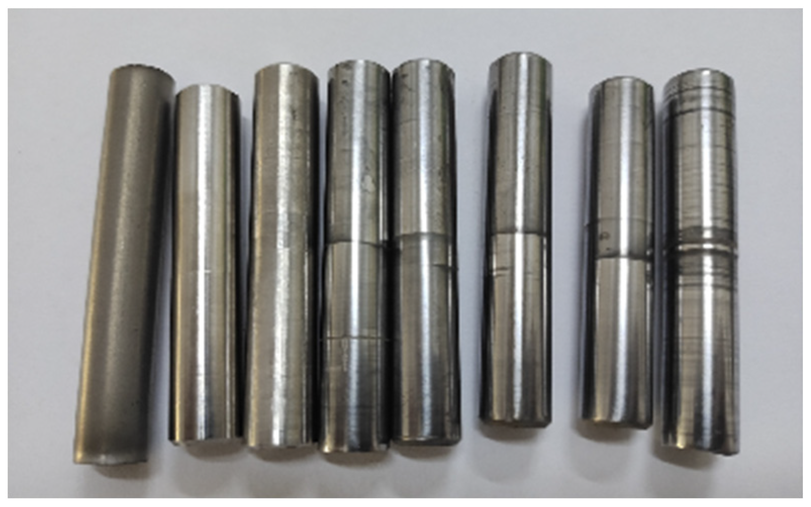
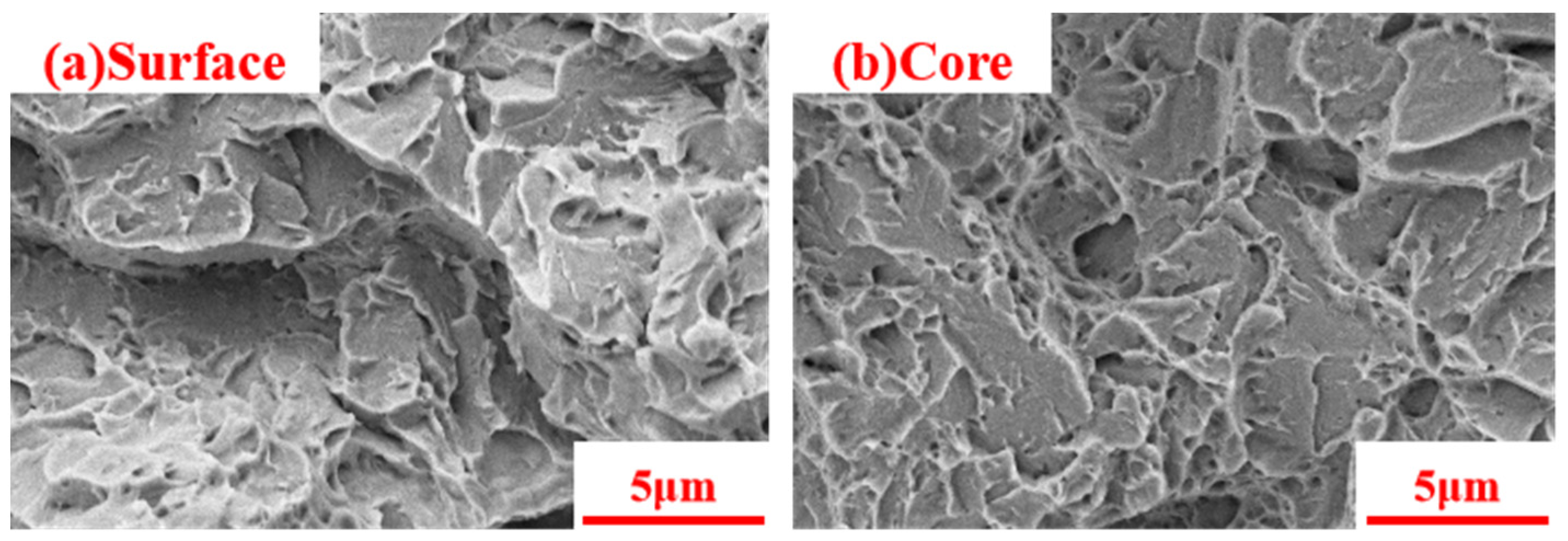
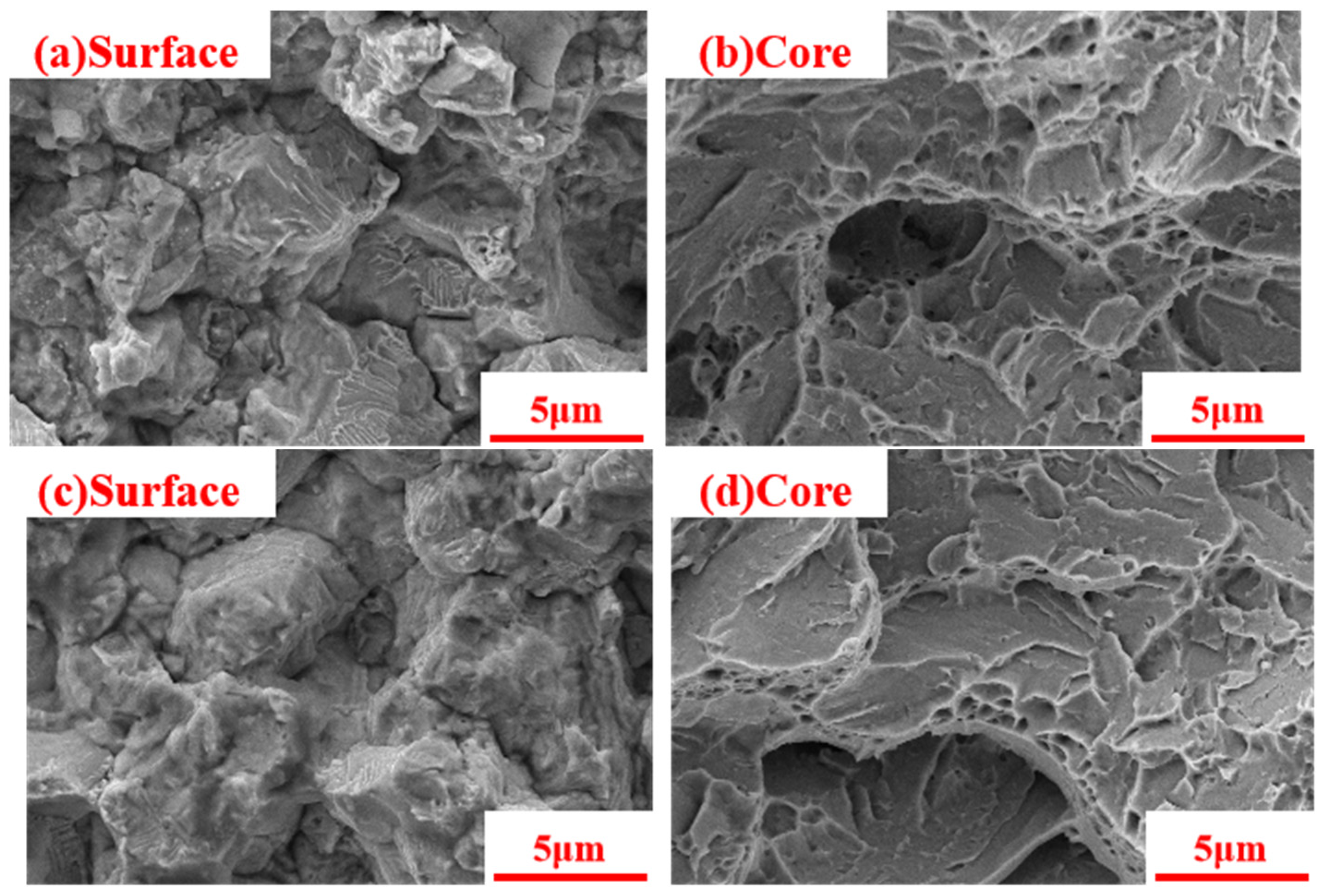
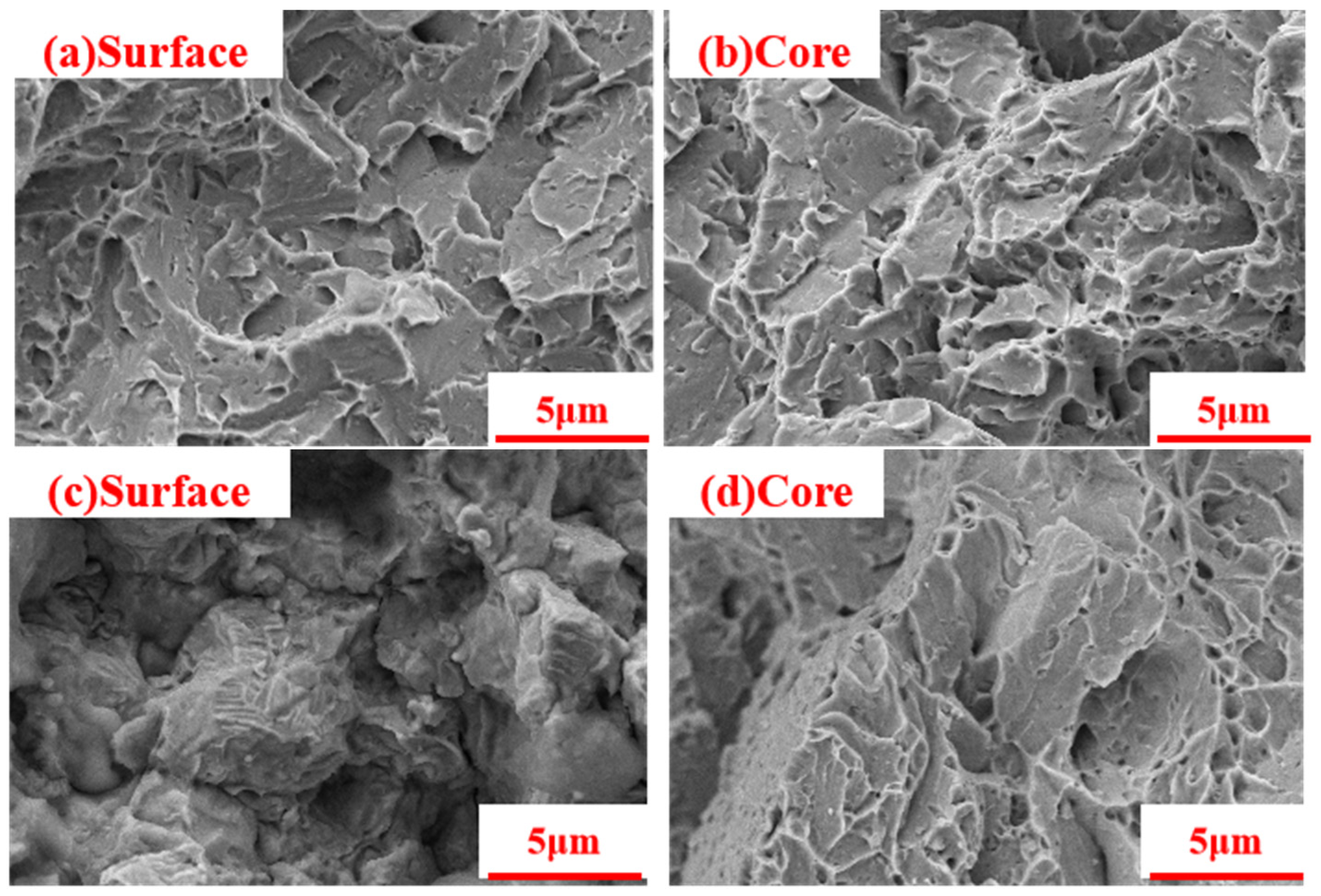
4.3. Analysis of Appearance of Fracture

An SEM analysis was conducted on the impact fracture treated with processes 1–7 with a CrossBCam 550 Zeiss scanning electron microscope. The fractures are shown in Figure 13, Figure 14, Figure 15 and Figure 16 to investigate the relationship between the high-energy composite modification process, the fracture properties of H13 steel, and the microstructure of the material. There are a large number of transgranular-type fractures and turbulence on the surface layer and central radiation areas of the fractures of the quenched and tempered QT sample (Figure 14), which are typical characteristics of transgranular-type fractures.
There were turbulences on the surface layer of the carburized CQT sample (Figure 15a). The fractures are quasi-transgranular-type fractures [8]. There are a large number of large and deep dimples in the central radiation area (Figure 15b). They are typical dimple-type fractures [26]. The dimples on the surface layer of the CQTL sample disappeared after laser treatment, leaving only turbulence and transgranular-type fractures (Figure 15c). They were transgranular-type fractures. The dimples in the radiation area of the CQTL sample became deeper (Figure 15d), which was consistent with the increase in impact toughness of the sample after laser shock.
There were a large number of turbulence and tearing edges on the surface layer of the nitrided QTN sample (Figure 16a). They are quasi-transgranular-type fractures. There are a large number of dimples in the central radiation area (Figure 16b). They are typical dimple-type fractures. The tearing edges on the surface layer of the QTNL sample vanished after laser treatment (Figure 16c), and they were transgranular-type fractures. The dimples in the central radiation area of the QTNL sample increased (Figure 16d), which was consistent with the increase in impact toughness of the sample after laser shock.
There were numerous turbulences and transgranular-type fractures on the surface layer of the carburized and nitrided CQTN sample (Figure 17a). They were transgranular-type [11] fractures. There were dimples in the central radiation area (Figure 17b). They were typical dimple-type fractures. The fractures on the surface layer of the CQTNL sample remained transgranular-type fractures after laser treatment (Figure 17c). The dimples in the central radiation area of the CQTNL sample became deeper (Figure 17d), which was consistent with the increase in impact toughness of the sample after laser shock.
Comparative analysis of the fracture characteristics after different heat treatment processes indicated that there are large and deep dimples in the central radiation area of the carburized CQT sample and the carburized laser CQTL sample, which is consistent with the high impact toughness of the impact sample. The dimples in the central radiation area of the carburized and nitrided CQTN sample and the carburized laser CQTNL sample basically disappeared, which was consistent with the minimum impact toughness. Therefore, it can be concluded that the hardness of the surface layer of the carburized laser CQTL sample is high [27], and the overall impact toughness is the best. “The surface is hard, and the core is tough”.
From the above impact fracture surface, it can be concluded that compared with the surface layer of H13 steel after carburizing or nitriding treatment, the center of the sample has a ductile fracture feature with multiple toughness pits. After carburizing or nitriding, the surface hardness of H13 steel increases, and a small amount of turbulences [11] appear on the fracture surface, resulting in fewer ductile dimples. After laser shock modification [27] of H13 steel, the residual stress on the surface increased, the hardness increased again, and there were numerous turbulences and transgranular-type fractures on the surface layer, presenting cleavage port characteristics.

5. Conclusions and Discussion

In this paper, the high-energy composite modification process is used to build a hardness gradient structure on the surface layer of impact samples of H13 steel, which is often used in the hob of the shield tunneling machine. The effects of microstructure and residual stress on the impact toughness and hardness of the samples were investigated, and the characteristics of fractures in the fiber and radiation areas of the sample were analyzed. The following main conclusions can be drawn:
  • By using a reasonable high-energy composite modification process, a suitable gradient structure can be constructed on the surface layer of the H13 steel sample. This allows the sample to have both good impact toughness and high surface hardness. Compared to homogeneous quenching and low-temperature tempering, the impact toughness and surface hardness of H13 steel treated with carburized laser have been significantly improved.
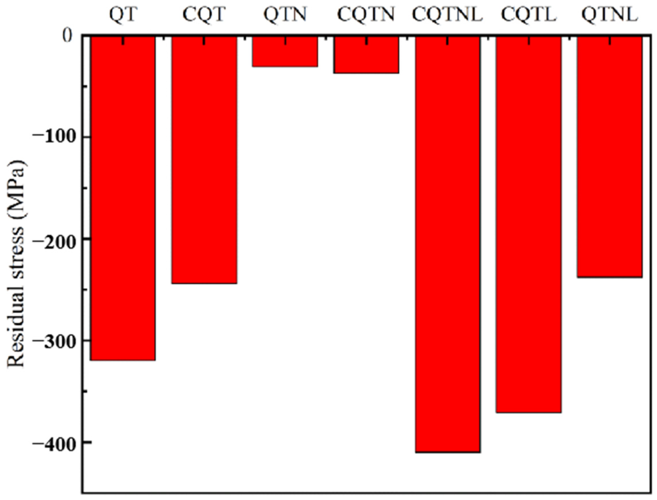
  • After composite laser modification, the residual compressive stress on the surface of the H13 steel sample increased, resulting in an increase in the surface hardness and impact toughness of the sample. Among them, the impact toughness of the carburized sample increased by 42.57%, the impact toughness of the nitrided sample increased by 107.5%, the impact toughness of the carburized nitrided sample increased by 20.16%, and the impact toughness of the carburized laser sample was the highest, reaching 15.64 J/cm2.
  • The samples treated with carburizing, nitriding, and a combination of carburizing and nitriding all had brittle fractures, with dimples present in the central radiation region. Among them, the carburized samples had large and deep dimples and the best impact toughness. The fiber area on the surface layer had a large number of turbulences and transgranular-type fractures. The fractures were transgranular-type or quasi-transgranular-type fractures.
  • The H13 steel sample after carburization and laser composite treatment has high surface hardness and impact toughness, with the best overall performance.
The working environment of shield tunneling machine hobs is complex, and this paper is conducted on standard samples in a laboratory environment, which has certain limitations. In future research, the impact of actual service environments will be considered. Especially for the upper soft and lower hard geological rock layers, the high-energy composite modification process of the actual cutting ring is optimized to achieve the optimal comprehensive performance.

Author Contributions

Conceptualization, Y.L., Z.X., X.C., Q.J. and Z.Z.; methodology, H.X.; software, H.X. and Y.L.; validation, Y.L., Z.X. and J.C. (Jun Cheng); investigation, J.C. (Junying Chen); resources, H.X. and Q.J.; data curation, H.X., X.C. and Y.L.; writing—original draft preparation, H.X.; writing—review and editing, Y.L. and J.C. (Jun Cheng); supervision, J.C; funding acquisition, Z.X. and Y.L. All authors have read and agreed to the published version of the manuscript.

Funding

This research was funded by the Major Science and Technology Project of Fujian, China (No. 2022HZ024009), the Major Science and Technology Project of Xiamen, Fujian, China (No. 3502Z20231011), the Natural Science Foundation of Fujian, China (Grant No. 2023H0013), and Education Research Project of Fujian Provincial Department of Education, China (Grant No. JAT200237).

Institutional Review Board Statement

Not applicable.

Informed Consent Statement

Not applicable.

Data Availability Statement

The data that support the findings of this study are available within the article.

Conflicts of Interest

The authors declare no conflict of interest.

References

  1. Li, X.; Wu, J.; Huo, P. Prediction Model for the Teeth Hob Cutter of Tunnel Boring Machines in High-content Quartzite Strata. KSCE J. Civ. Eng. 2023, 27, 371–383. [Google Scholar] [CrossRef]
  2. Ye, F.; Qin, N.; Gao, X.; Quan, X.-Y.; Qin, X.-Z.; Dai, B. Shield Equipment Optimization and Construction Control Technology in Water-Rich and Sandy Cobble Stratum: A Case Study of The First Yellow River Metro Tunnel Undercrossing. Adv. Civ. Eng. 2019, 2019, 1–12. [Google Scholar] [CrossRef]
  3. Zhang, Y.; Yang, X.; Wang, S.; Li, W.; Wu, Q.; Zhao, W.; Gao, Y.; Wang, K. Research on Tribological Properties of H13 Steel of Shield Machine Hob by Laser Shot Peening. Int. J. Adv. Manuf. Technol. 2022, 119, 7121–7131. [Google Scholar] [CrossRef]
  4. An, Y.; Li, M.; Chen, S.; Hu, Y.; Zhang, A.; Zhai, Y. Dynamic Simulation and Thermal Analysis of Rock Breaking Force on Disc Cutter of Tunnel Boring Machine. In Proceedings of the 2019 4th International Conference on Mechanical, Control and Computer Engineering (ICMCCE), Hohhot, China, 24–26 October 2019; IEEE: Piscataway, NJ, USA, 2019; pp. 1015–10155. [Google Scholar]
  5. Zhu, C.X.; Liu, W.W.; Wang, W.; Zhu, L. Static Analysis of Double-Edged Rock-Breaking Hob Based on Finite Element. Appl. Mech. Mater. 2013, 415, 502–505. [Google Scholar]
  6. Telasang, G.; Majumdar, J.D.; Padmanabham, G.; Manna, I. Wear and Corrosion Behavior of Laser Surface Engineered AISI H13 Hot Working Tool Steel. Surf. Coat. Technol. 2015, 261, 69–78. [Google Scholar] [CrossRef]
  7. Ren, D.J.; Shen, J.S.; Chai, J.C.; Zhou, A. Analysis of Disc Cutter Failure in Shield Tunnelling Using 3D Circular Cutting Theory. Eng. Fail. Anal. 2018, 90, 23–35. [Google Scholar] [CrossRef]
  8. Jagota, V.; Sharma, R.K. Impact of Austenitizing Temperature on The Strength Behavior and Scratch Resistance of AISI H13 Steel. J. Inst. Eng. (India) Ser. D 2020, 101, 93–104. [Google Scholar] [CrossRef]
  9. Zhu, J.; Zhang, Z.; Xie, J. Improving Strength and Ductility of H13 Die Steel by Pre-Tempering Treatment and Its Mechanism. Mater. Sci. Eng. A 2019, 752, 101–114. [Google Scholar] [CrossRef]
  10. Peng, T.; Zhao, X.; Chen, Y.; Tang, L.; Wei, K.; Hu, J. Improvement of Stamping Performance of H13 Steel by Compound-Layer Free Plasma Nitriding. Surf. Eng. 2020, 36, 492–497. [Google Scholar] [CrossRef]
  11. Wang, J.; Xu, Z.; Lu, X. Effect of The Quenching and Tempering Temperatures on The Microstructure and Mechanical Properties of H13 Steel. J. Mater. Eng. Perform. 2020, 29, 1849–1859. [Google Scholar] [CrossRef]
  12. Lee, H.H.; Park, H.K.; Jung, J.; Amanov, A.; Kim, H.S. Multi-Layered Gradient Structure Manufactured by Single-Roll Angular-Rolling and Ultrasonic Nanocrystalline Surface Modification. Scr. Mater. 2020, 186, 52–56. [Google Scholar] [CrossRef]
  13. Fu, H.; Liang, Y. Study of The Surface Integrity and High Cycle Fatigue Performance of AISI 4340 Steel After Composite Surface Modification. Metals 2019, 9, 856. [Google Scholar] [CrossRef]
  14. Zou, J.; Liang, Y.; Jiang, Y.; Yin, C.; Huang, C.; Liu, D.; Zhu, Z.; Wu, Y. Fretting Fatigue Mechanism of 40crnimoa Steel Subjected to the Ultrasonic Surface Rolling Process: The Role of the Gradient Structure. Int. J. Fatigue 2023, 167, 107383. [Google Scholar] [CrossRef]
  15. Lou, L.; Wang, X.; Wu, W.; Qin, W. Research on Rock Breaking Characteristics of Impact Hob of Hard Rock Excavator. J. Vibroeng. 2023, 25, 615–629. [Google Scholar] [CrossRef]
  16. Li, X.; Di, H.; Zhou, S.; Huo, P.; Huang, Q. Effective Method for Adjusting the Uplifting of Shield Machine Tunneling in Upper-Soft Lower-Hard Strata. Tunn. Undergr. Space Technol. 2021, 115, 104040. [Google Scholar] [CrossRef]
  17. Wu, X.; Cheng, J.; Xu, Z.; Dai, L.; Jiang, Q.; Su, B.; Zhu, L.; Zhao, Z. Exploration of Key Process Parameters and Properties of 40Cr Steel in Ultrasonic Surface Rolling Process. Coatings 2022, 12, 1353. [Google Scholar] [CrossRef]
  18. Chen, X.; Sun, J.; Xu, Z.; Chen, J.; Jiang, Q.; Li, Y.; Li, J.; Cheng, J. Optimization of Laser Shock Process Parameters for 40Cr Steel. Coatings 2022, 12, 1872. [Google Scholar] [CrossRef]
  19. Üstündag, Ö.; Bakir, N.; Gumenyuk, A.; Rethmeier, M. Improvement of Charpy Impact Toughness by Using an AC Magnet Backing System for Laser Hybrid Welding of Thick S690QL Steels. Procedia CIRP 2022, 111, 462–465. [Google Scholar] [CrossRef]
  20. Yan, J.; Song, H.; Dong, Y.; Quach, W.-M.; Yan, M. High Strength (~2000 Mpa) or Highly Ductile (~11%) Additively Manufactured H13 by Tempering at Different Conditions. Mater. Sci. Eng. A 2020, 773, 138845. [Google Scholar] [CrossRef]
  21. Sun, J.; Li, J.; Chen, X.; Xu, Z.; Lin, Y.; Jiang, Q.; Chen, J.; Li, Y. Optimizing Parameters with FEM Model for 20crmnti Laser Shocking. Materials 2022, 16, 328. [Google Scholar] [CrossRef] [PubMed]
  22. Umarfarooq, M.A.; Gouda, P.S.; Kumar, G.V.; Banapurmath, N.; Edacherian, A. Impact of Process Induced Residual Stresses on Interlaminar Fracture Toughness in Carbon Epoxy Composites. Compos. Part A Appl. Sci. Manuf. 2019, 127, 105652. [Google Scholar] [CrossRef]
  23. Niu, J.B.; Zhang, X.H.; Ma, X.X.; Liu, Y.; Wang, L.Q.; Wu, T.B. Characterization of Vein-Like Structures Formed in Nitrided Layers during Plasma Nitriding of 8Cr4Mo4V Steel. Materialia 2022, 22, 101378. [Google Scholar] [CrossRef]
  24. Chen, W.; Huang, Y.; Xiao, H.; Meng, X.; Li, Z.; Chen, Z.; Hong, Y.; Wu, C. The Thermal Process for Hardening the Nitrocarburized Layers of A Low-Carbon Steel. Scr. Mater. 2022, 210, 114467. [Google Scholar] [CrossRef]
  25. Chen, J.; Li, S.; Liang, Y.; Tian, X.; Gu, J. Effect of Carburizing and Nitriding Duplex Treatment on The Friction and Wear Properties of 20crni2mo Steel. Mater. Res. Express 2023, 10, 036507. [Google Scholar] [CrossRef]
  26. Zhou, W.; Zhu, J.; Zhang, Z. Austenite Grain Growth Behaviors of La-Microalloyed H13 Steel and Its Effect on Mechanical Properties. Met. Mater. Trans. A 2020, 51, 4662–4673. [Google Scholar] [CrossRef]
  27. Shakerin, S.; Sanjari, M.; Amirkhiz, B.S.; Mohammadi, M. Interface Engineering of Additively Manufactured Maraging Steel-H13 Bimetallic Structures. Mater. Charact. 2020, 170, 110728. [Google Scholar] [CrossRef]
Figure 1. Shield tunneling machine hob. (a) Hob ring of Shield; (b,c) the force state of the hob.
Coatings 13 01482 g001
Figure 2. Schematic diagram of high-energy composite modified surface of the sample. (In the enlarged image, a square represents the infiltrated carbon particles, and a circle represents the infiltrated nitrogen atoms).
Coatings 13 01482 g002
Figure 3. H13 steel carburizing and quenching treatment process. The black dot represents the omission of the timeline length, and the dashed line corresponds to the matching time point.
Coatings 13 01482 g003
Figure 4. Nitriding temperature curve of H13 steel. The black dot represents the omission of the timeline length.
Coatings 13 01482 g004
Figure 5. Partial experimental samples of H13.
Coatings 13 01482 g005
Figure 6. Impact toughness and maximum surface layer hardness under different processes conditions.
Coatings 13 01482 g006
Figure 7. Hardness distribution of H13 steel sample in the direction of depth.
Coatings 13 01482 g007
Figure 8. Metallographic structures of the quenched and low-temperature-tempered QT sample.
Coatings 13 01482 g008
Figure 9. X-ray diffraction pattern of H13 steel sample. Sample No.1: QT; Sample No.2: CQT; Sample No.3: QTN; Sample No.4: CQTN; Sample No.5: CQTNL; Sample No.6: CQTL; Sample No.7: QTNL.
Coatings 13 01482 g009
Figure 10. Metallographic structures of carburized structure of H13 alloy; (a) surface of CQT samples; (b) core of CQT samples; (c) surface of CQTL samples; (d) core of CQTL samples.
Coatings 13 01482 g010
Figure 11. Surface residual stress of H13 steel sample.
Coatings 13 01482 g011
Figure 12. Metallographic structures of nitrided structure of H13 alloy; (a) surface of QTN samples; (b) core of QTN samples; (c) surface of QTNL samples; (d) core of QTNL samples.
Coatings 13 01482 g012
Figure 13. Metallographic structures of carburized and nitrided structure of H13 alloy; (a) surface of CQTN samples; (b) core of CQTN samples; (c) surface of CQTNL samples; (d) core of CQTNL samples.
Coatings 13 01482 g013
Figure 14. Morphology of impact fractures in quenched and tempered QT samples on the surface layer and in the core.
Coatings 13 01482 g014
Figure 15. Morphology of impact fractures in a carburized samples on the surface layer and in the core; (a) surface of CQT samples; (b) core of CQT samples; (c) surface of CQTL samples; (d) core of CQTL samples.
Coatings 13 01482 g015
Figure 16. Morphology of impact fractures in a nitrided sample on the surface layer and in the core; (a) surface of QTN samples; (b) core of QTN samples; (c) surface of QTNL samples; (d) core of QTNL samples.
Coatings 13 01482 g016
Figure 17. Morphology of impact fractures in a carburized and nitrided sample on the surface layer and in the core; (a) surface of CQTN samples; (b) core of CQTN samples; (c) surface of CQTNL samples; (d) core of CQTNL samples.
Coatings 13 01482 g017
Table 1. Chemical composition of H13 steel, wt%.
ElementCSiMnCrMoVPS
Content0.411.030.45.051.270.890.0220.002
Table 2. Critical transition temperature of H13 steel.
Critical PointAc1Ac3Ar1Ar3MsMf
Temperature (°C)860915775815340215
Table 3. Form of laser shock process parameters.
ProcessLap RateEnergy/JPulse Width/nsSpot Diameter/mm
Parameters0.411.030.45.05
Table 4. Heat treatment hardening process of H13 steel.
ProcessQuenching (Q)Tempering (T)Carburizing (C)Nitriding (N)High-Energy Modification (L)
ParametersT/°CT/°CT/°Ct/hT/°Ct/hP/kPaGas/L·min−1
No.11020300QT
No.210205109506CQT
No.310205104808300N2:H2 = 0.45:0.15QTN
No.4102051095064808300N2:H2 = 0.45:0.15CQTN
No.5102051095064808300N2:H2 = 0.45:0.15LaserCQTNL
No.610205109506LaserCQTL
No.710205104808300N2:H2 = 0.45:0.15LaserQTNL
Disclaimer/Publisher’s Note: The statements, opinions and data contained in all publications are solely those of the individual author(s) and contributor(s) and not of MDPI and/or the editor(s). MDPI and/or the editor(s) disclaim responsibility for any injury to people or property resulting from any ideas, methods, instructions or products referred to in the content.

