Abstract
Fourth-generation nuclear power systems are based on high-temperature gas-cooled reactors, in which the pebble fuel is the primary energy carrier. In this regard, applying protective pyrocarbon coatings on granulated fuel is an essential problem in ensuring the reliability of nuclear power plants. The article’s main idea is to research rational technological parameters of forming a pyrocarbon protective coating on the granules of a nuclear fuel model. For this purpose, granulated Al2O3 with the protective pyrocarbone coating was applied as a fuel model. The article’s aim is to study the effect of thermophysical parameters on applying a protective pyrocarbon coating on granulated Al2O3. During the experimental studies, thermal imaging of the pyrolysis process was used. The scientific novelty of the work is the equilibrium curves for the systems Al2O3:CH4, Al2O3:CH4:N2, and Al2O3:CH4:Ar. Their analysis allowed for evaluating rational thermochemical parameters of the pyrolysis process. As a result, rational thermophysical parameters of coating granulated Al2O3 with a pyrocarbon layer were evaluated, and the practical possibility of applying the pyrocarbon coating to granulated Al2O3 in the electrothermal fluidized bed was experimentally proven. It was shown that nitrogen does not significantly affect the target reaction product under a temperature of less than 1500 K. Also, the rational conditions for the pyrocarbon coating at a pressure of 0.1 MPa were realized at a temperature of 900–1500 K and using argon. Moreover, pyrocarbon was precipitated from hydrocarbon at 1073–1273 K. Overall, the need to add an inert gas for reducing the carbon black formation was proven to prevent a reduction of natural gas efficiency.
1. Introduction
The significance of the operational safety problem of existing and designed nuclear power plants (NPP) is closely related to the operation and development of the entire nuclear power complex. Simultaneously, the critical role of nuclear energy in the energy supply is undeniable [1].
Kalinowski et al. [2] described the origins of scientific developments in pyrocarbon coatings of nuclear fuel in the middle of the 20th century. In particular, it was noted that such experimental studies began from the pyrolysis of hydrocarbons in fluid reactors with beds of sand, graphite, sintered aluminum oxide (Al2O3), and other granular materials. As a result, such works allowed for evaluating the concentration of fission products in the coatings after prolonged activation of the fuel.
Also, Long et al. [3] studied the performance of irradiated particles taking their origin from the high-temperature gas-cooled reactors (HTGR) base technology program on fuel graphite development, operated by the Union Carbide Corporation for the US Department of Energy.
Moreover, Tepest [4] studied the parameters of pyrocarbon coatings deposited on fuel particles for high-temperature reactors using X-ray microbeam measurements on single particles for individual coatings.
Nowadays, one of the promising technical solutions to increase the safety of NPP is the use of reactors with pebble fuel elements—fuel microspheres of material divided under neutron radiation (e.g., dioxide of uranium, plutonium, and thorium) with layers of protective coatings (e.g., pyrocarbon, carbides of silicon and zirconium, titanium nitride) [5,6,7].
Protective coatings on the fuel elements of nuclear power reactors perform multiple functions, although its main purpose is the retention of divided products inside. Therefore, even in an emergency at the reactor, pebble fuel elements around NPP release radioactive particles into the atmosphere. Furthermore, Knol [8] stated that these elements could be assembled using special mechanical devices.
Pebble fuel is the primary energy carrier for HTGR. Such a type of reactor belongs to fourth-generation nuclear power systems [9,10]. These are nuclear reactors in which nuclear fuel has a substantially short half-life.
One of the critical components of pebble fuel is a protective pyrocarbon coating. Studies on producing pyrocarbon coatings for various purposes are carried out on appropriate models.
The development of HTGR-TRISO coated fuels in the globe was discussed in [11] for UO2-coated fuel particles and advanced fuel with ZrC coating. Also, Horvath and Rachlew [12] studied the kinetics of the release of fission products from particles of micro-fuel-coated HTGR. As a result, an effect of the trapped fraction and limited solubility on the concentration profile at the boundary between the coating layers was determined.
Ivanov et al. [13,14] evaluated fission products from coated fuel particles at HTGR. These results are based on considering chemical bonding, the effects of limited solubility, and changes in the concentration of components at the boundaries between coating layers.
Roos [15] studied a multilayer protective coating of C/C-SiC composites by chemical vapor deposition. A pyrocarbon layer and a coating of SiC were considered. As a result, it was obtained that Si3N4 and Al2O3 top layers protect against oxidation and corrosion and provide for stable operations at the high-temperature range.
Liu et al. [16] studied composites with a pyrocarbon matrix reinforced with carbon nanotubes. Such structures significantly increased the service life of composites in high-temperature environments under similar mechanical properties.
Xu et al. [17] studied the mechanical properties of SiC coatings applied to C/C composites. As a result, they showed that these coatings have lower residual stresses, higher hardness, and Young’s modulus. This positively impacts the resistance of the coating to cracking and contributes to improving its antioxidant characteristics.
Studies on the mechanical properties of these coatings have also been further developed. Mainly, Xu et al. [18] studied the effect of pyrocarbon texture on the microstructure of the coating. Duan [19] studied the tensile strength and fracture strain of composites.
Chernikov [20] obtained the main characteristics of materials and components of spherical pebble fuel. His study included microspheres of uranium dioxide, pyrocarbon and silicon carbide protective layers, coated fuel particles, and matrix graphite. Also, López-Honorato et al. [21] studied the structure and mechanical properties of pyrolytic carbon produced by fluidized bed chemical vapor deposition.
Xu et al. [22] proved an increase in the strength and toughness of the composite, which is associated with multiple effects of deformation of carbon layers, deflection, and crack propagation caused by bridge zones, sublayers, nano-, and microcracks.
Kurbakov [23] investigated the effect of cracks in the inner pyrocarbon layers on damage to silicon carbide layers. As a result, it was determined that the introduction of pyrolytic carbon into the inner layer or the formation of “pyrocarbon—silicon carbide” compositions (“silicon carbide—carbon”, Ti3SiC2, ZrC, TiC, and nitrides of Zr, Ti, Al) on the inner interface leads to internal cracks. This fact increases the radiation–chemical resistance of the carbide layer and micro fuel.
Ilinich et al. [24] investigated mesoporous carbon infiltrated Al2O3 with a relatively thin carbon coating. The obtained product had high electrical conductivity and resistance to acidic media.
Opyatyuk et al. [25] studied the point defects influencing NPP operations with a uranium fuel medium. As a result, the dependence between point defect formation and fissile temperature for the uranium–thorium medium was obtained.
Yang et al. [26,27] investigated the process of formation of pyrocarbon during thermochemical treatment, consisting of carbonization and halogenation to isolate radionuclides from waste cation exchange resin. It was also detected that a part of the adsorbed particles of radiocarbon 14C turns into a thermostable pyrocarbon when the temperature rises to 1000 °C.
Moreover, Zhan et al. [28] applied a convolution neural network for fuel reloading optimization of block-type nuclear reactors. The results showed that the developed approach allows for predicting rational parameters for HTGRs.
Thus, the analysis of the above studies shows that experimental research in obtaining pyrocarbon coatings is aimed at analyzing the properties of existing coatings but not at studying the process of coating on model pebble particles.
Moreover, because of previous research on coatings on the model of the pebble nuclear fuel (SiO2, Dy2O3, Gd2O3, Sm2O3), batches of pyrocapsulated material with pyrocarbon content were developed in a wide range of 6–97% mass [29]. Due to the complexity of obtaining Dy2O3, Gd2O3, and Sm2O3, these models are highly expensive. Consequently, their use is economically impractical for broader research. On the other hand, using SiO2 particles is limited due to their geometry. Therefore, granular Al2O3 has been chosen as the most appropriate model of the pebble fuel elements. The granules have sufficient mechanical strength [30]. This prevents accelerated particles’ abrasion and the formation of a fine fraction while applying a pyrocarbon coating in an electrothermal fluidized bed.
Remarkably, despite many publications, the process of applying pyrocarbon coating is not sufficiently studied. Therefore, the aim of the article is to study the influence of thermophysical parameters on applying a protective pyrocarbon coating on granules of Al2O3. The main objectives allow solving the following scientific gaps. First, a laboratory installation for the experimental study of applying a protective pyrocarbon coating should be created. Second, the practical possibility of applying the pyrocarbon coating to granulated Al2O3 in the electrothermal fluidized bed should be experimentally proven.
The scientific novelty of this work is to determine rational thermochemical parameters for coating the nuclear fuel model’s granules with a protective pyrocarbon shell.
2. Materials and Methods
The research was conducted in two stages. The first step evaluated the thermochemical parameters of the pyrolysis process using numerical simulation. For this purpose, the “TERRA” software was applied based on equilibrium thermodynamics [31].
The theoretically obtained optimal technological process parameters were tested on an experimental stand in the second stage. The process of applying the formed pyrocarbon to Al2O3 granules was studied. As a result, the main technological (i.e., gas consumption, voltage, current, and heat loss) and thermochemical parameters (i.e., a ratio of components and temperature range) were determined. Microscopic analysis of the original and coated material was also carried out to determine a pyrocarbon coating on the spheres Al2O3.
Calculation of thermodynamic equilibrium for an arbitrary multicomponent system includes evaluating equilibrium parameters, thermodynamic properties, and chemical and phase composition. At a relatively high temperature (when any state changes are accompanied by phase, polymorphic, and chemical transformations), this problem becomes more challenging than under the classical thermodynamics statements. However, since the fundamental thermodynamic laws remain valid for any system, their application allows calculating thermodynamic equilibrium in a general case. Consideration within a unified approach of significantly different processes and states is possible only with a known formalization of the model description of the studied objects.
A thermodynamic system under consideration is characterized by the relative and absolute content of chemical elements (mol/kg). It remains unchanged when equilibrium is established from an arbitrary state and is sufficient to describe the system.
The thermodynamic modeling method was implemented to analyze the carbon–thermal interaction using the above-mentioned “TERRA” software. It is based on the principle of maximum entropy. It considers properties of the reacting components in the thermodynamic system, supplementing it with the Gibbs thermodynamic-diagram approach of designing concentration triangles [32].
The system’s composition (e.g., in mol, kg, % mass, and partial pressure) and the thermodynamic parameters (pressure, temperature, volume, internal energy, enthalpy, and entropy) describe the equilibrium state. Other characteristics were calculated according to fundamental thermodynamic relations.
The initial data for the calculation are the initial composition of the system (i.e., mole fractions of Al2O3:CH4) in the ratio of 1:3, as well as Al2O3:CH4:N2 = 1:3:0.5, Al2O3:CH4:Ar = 1:3:0.5, and Al2O3:CH4:Ar = 1:5:0.5. The temperature range is 400–2300 K under the pressure of 0.1 MPa.
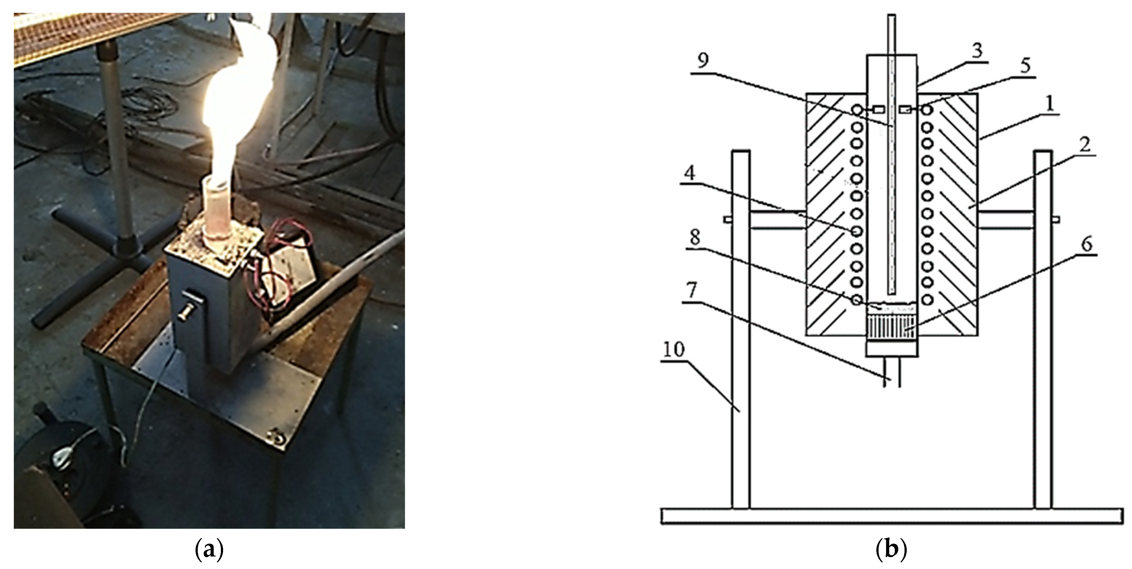
A reactor with an electrothermal fluidized bed was designed to study the process of applying a protective pyrocarbon coating on the chosen model (Figure 1).
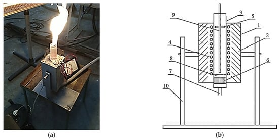
Figure 1.
The experimental reactor (a) and its design scheme (b): 1—outer casing; 2—thermal insulation; 3—quartz tube; 4—heater; 5—heater clamps; 6—gas distribution lattice; 7—fitting for gas supply; 8—fluidized bed of granular Al2O3; 9—thermocouple; 10—support with the movable mechanism.
The reactor consists of a metal outer casing 1, which contains a layer of thermal insulation made of heat-resistant material “P-130” with a quartz tube 3 inside. A round quartz tube 3 and heater 4 are placed. It is made of nickel wire connected to the heater clamps 5. In the lower part of quartz tube 3, a gas distribution lattice 6 is placed. It is connected at the bottom with the fitting for gas supply 7 to create a fluidized bed 8. Inside the quartz tube 3, a thermocouple 9 is placed. The whole design is fixed on a support with the movable mechanism 10.
The reactor works as follows. A mixture of natural gas and an inert environment is fed through the fitting for the gas supply 6 to the gas distribution lattice 7, which creates a fluidized bed 8 of granulated Al2O3. The reaction zone is heated by current passing through a nickel–chromium winding—heater 4. The temperature is measured by the thermocouple 9. The treated material is unloaded into a special heat-resistant cylinder by inverting the installation.
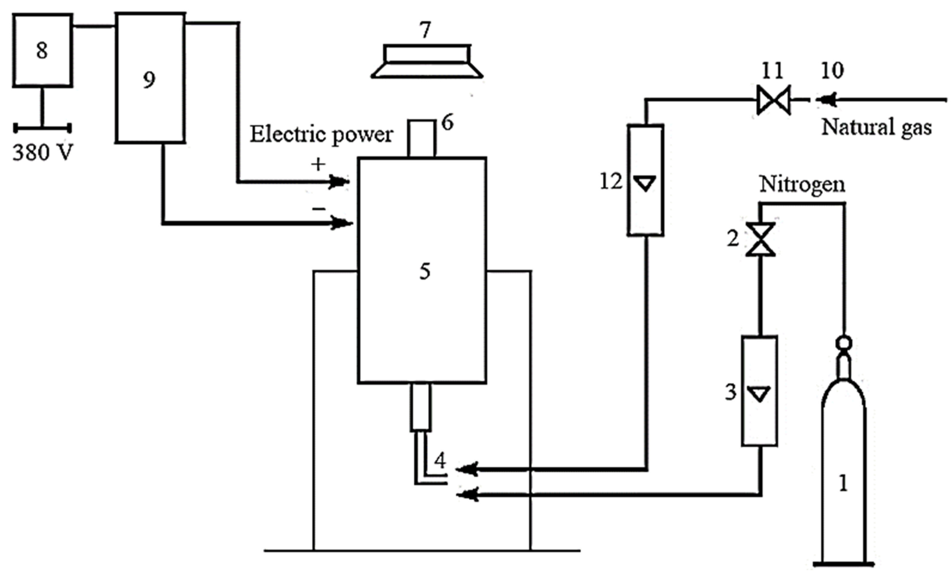
Figure 2 presents the technological scheme of the installation with a reactor for applying a pyrocarbon coating.

Figure 2.
Schematic technological scheme of the installation: 1—cylinder with inert environment; 2—valve for nitrogen supply; 3—rotameter for nitrogen; 4—fitting for gas supply; 5—reactor; 6—the upper part of the reactor; 7—gas hood; 8—switch; 9—power transformer; 10—natural gas supply source; 11—valve for natural gas supply; 12—rotameter for natural gas.
The installation works as follows. The inert environment is fed into reactor 5 by opening the reducer on cylinder 1 and valve 2 through rotameter 3 to create a fluidized bed and an inert atmosphere. After passing reactor 5 through the upper part 6, the nitrogen supplies to the gas hood 7. After turning on switch 8, voltage is applied to reactor 5 through the power transformer 9. After obtaining the proper temperature mode, natural gas is supplied from the natural gas supply source 10, valve 11, rotameter 12, and fitting 4. It gradually replaces the inert environment (nitrogen). Natural gas and inert environment consumption are measured by rotameters 12 and 3, respectively.
Hydrocarbons are used in pyrolysis for granules’ carbonization (protective coating). Particularly, methane is used because other hydrocarbons (propane–butane and heavier hydrocarbons) lead to the formation of liquid components that contaminate the power reactor (hydrocarbons above methane liquefy at such pressure and temperature).
Pyrocarbon was precipitated by pyrolysis of hydrocarbons in the reactor at 1073–1273 K. Natural gas was used as the fluidizing agent, and granular Al2O3 was used as the fluidized bed. An inert environment needs to be applied to reduce the formation of technical carbon black. In the inert environment, the carbon is deposited precisely as pyrocarbon. The main operating and technological parameters of the installation are presented in Table 1.

Table 1.
Process parameters of the experimental setup.
The pyrometer “IR-866 U” (“FLUS”, China) was used for the measurement range of 220–2550 K, and the measurement error of ±1.5% + 2.0 K. The K-type thermocouple “UNI-TUT325” (“UNIT”, China) connected to a digital thermometer was used for measurements in a range of 220–1500 K, and the measurement error of ±0.5% + 1.0 K. The thermal imager “HT-04D” (“XINTEST”, China) was used to measure real-time heat loss for the measurement range of 250–680 K and measurement error of ±2%/±2 K.
Investigations of the surfaces of untreated and treated Al2O3 were performed using the digital microscope “SuperZoom” (“Magnifier”, China). Since Al2O3 is resistant to oxidation by air at temperatures higher than 893 K, the pyrocarbon content was determined by the ash content of graphite by GOST 17818.4-90 “Graphite. Method for determining the ash content”. A batch of granules was weighed before and after coating (m1 and m2, respectively). The mass fraction of pyrocarbon coating is determined as follows:
where m1, m2—mass of batches of granules before and after coating, respectively.
The measurement error of the weights did not exceed 0.5 mg.
The mass of granules before and after coating are as follows:
where d—diameter of granules, m; h—thickness of the pyrocarbon coating, m; ρ0 = 3950 kg/m3—density of Al2O3 granules; and ρc = 1660 kg/m3—density of pyrocarbon coating.
After the substitution of expression (2) to Formula (1), the following dependency for evaluating the thickness of pyrocarbon coating can be obtained:
In experimental studies, the purest materials were used to reduce the impact of side reactions on the process. Particularly, gaseous argon has the following composition of volume fractions: argon—99.993%, oxygen—0.0006%, nitrogen—0.005%, water vapor—0.0009%, and CO2—0.0005%.
Gaseous nitrogen has the following composition of volume fractions: nitrogen—99.999%, oxygen—0.0004%, water vapor—0.0002%, hydrogen—0.0002%, and carbon-containing compounds in terms of CH4—0.0002%. Gaseous methane has the following composition of volume fractions: methane—99.9%, nitrogen—0.035%, oxygen—0.023%, ethane—0.013%, propane—0.015%, and water vapor—0.014%. Granules of Al2O3 have the following composition of mass fractions: Al2O3—99.93%, Fe—0.04%, and Na—0.03%.
To determine the size of the granules, processing of their photos using the “Digimizer” software was used. The root mean square deviation of the measurement was 0.014 mm.
3. Results
Different ratios of Al2O3:CH4 are used to experimentally study the pyrolysis process (thermal decomposition) to determine the effect of increasing the concentration of CH4 for applying a pyrocarbon coating on granular Al2O3. Due to physical–chemical characteristics, granulated Al2O3 has been chosen as a model of microspherical nuclear fuel. The calculations of methane pyrolysis for applying pyrocarbon coating on granular Al2O3 are presented below.
The following results were obtained based on the analytical modeling results to determine the rational parameters of applying pyrocarbon coatings on granular Al2O3 in an electrothermal fluidized bed reactor. These results allow for evaluating the rational thermochemical parameters to deposit pyrocarbons during the pyrolysis of hydrocarbons by thermodynamic methods. The content of substances was determined by spectral analysis during experimental studies.
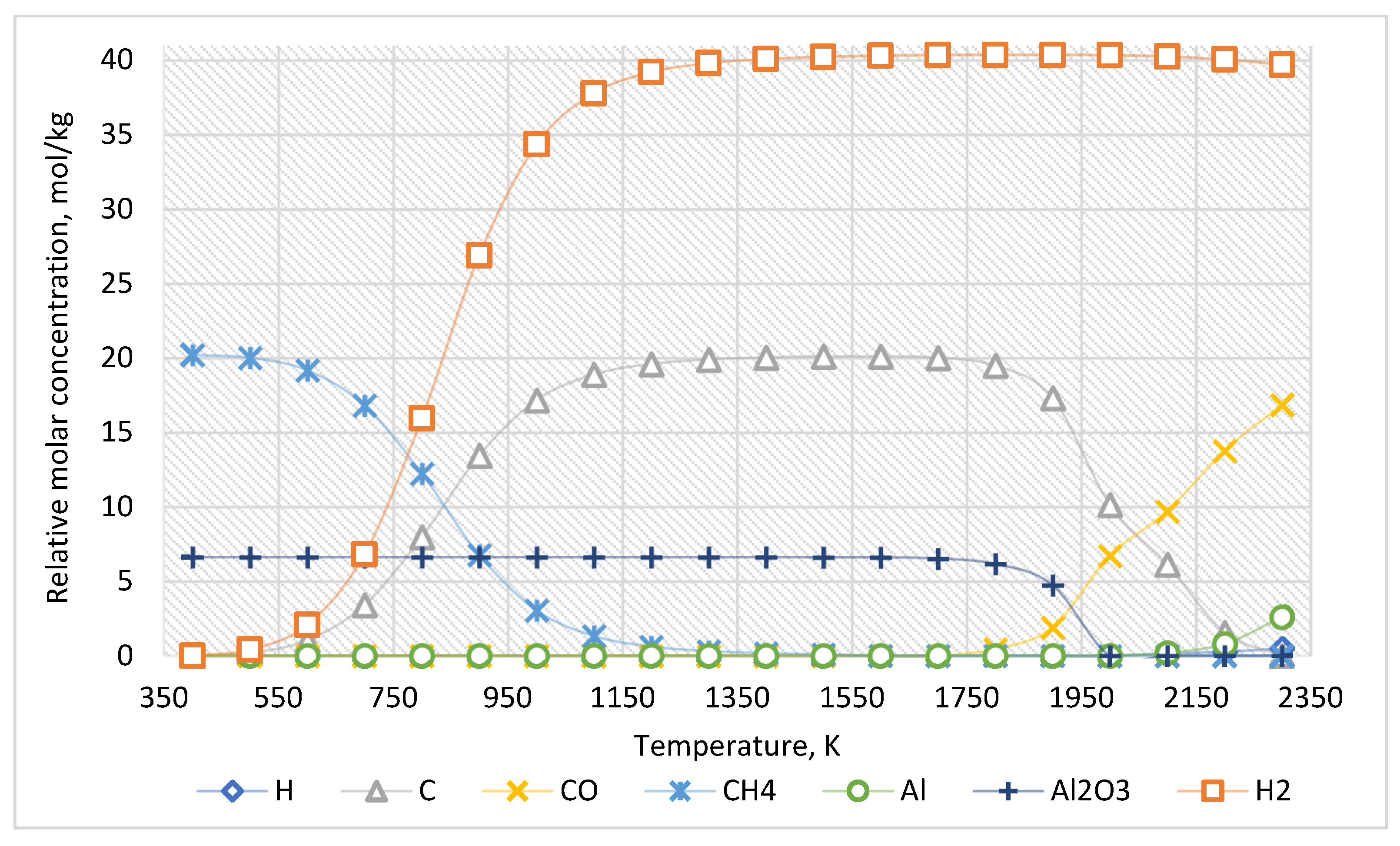
For the approximate determination of reaction products, the calculation results for the case of the ratio of Al2O3:CH4 = 1:3 are presented in Figure 3. The equilibrium composition of this system is presented in Table 2.

Figure 3.
The equilibrium curves of this system “Al2O3:CH4 = 1:3”.
Table 2.
The equilibrium composition of the system “Al2O3:CH4 = 1:3”, mol/kg.
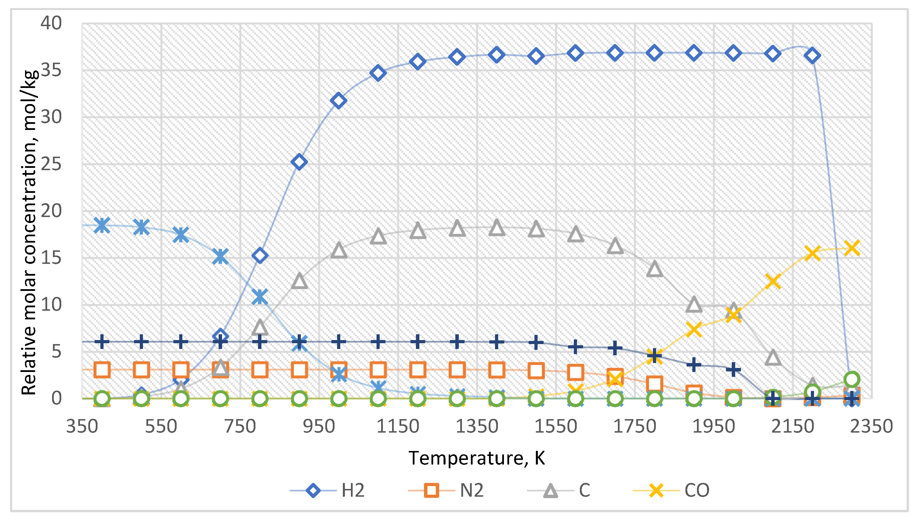
The equilibrium curves of the system “Al2O3:CH4:N2 = 1:3:0.5” are presented in Figure 4. The equilibrium composition of the system is presented in Table 3.
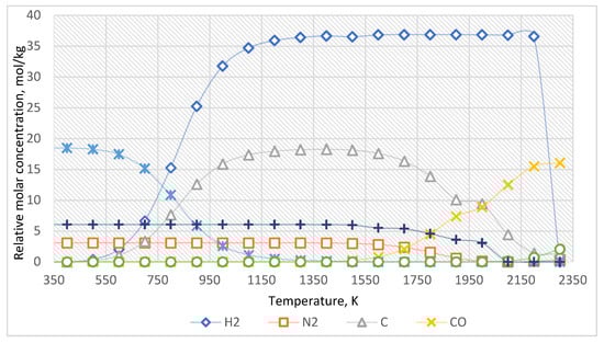
Figure 4.
The equilibrium curves of this system “Al2O3:CH4:N2 = 1:3:0.5”.
Table 3.
The equilibrium composition of the system “Al2O3:CH4:N2 = 1:3:0.5”, mol/kg.
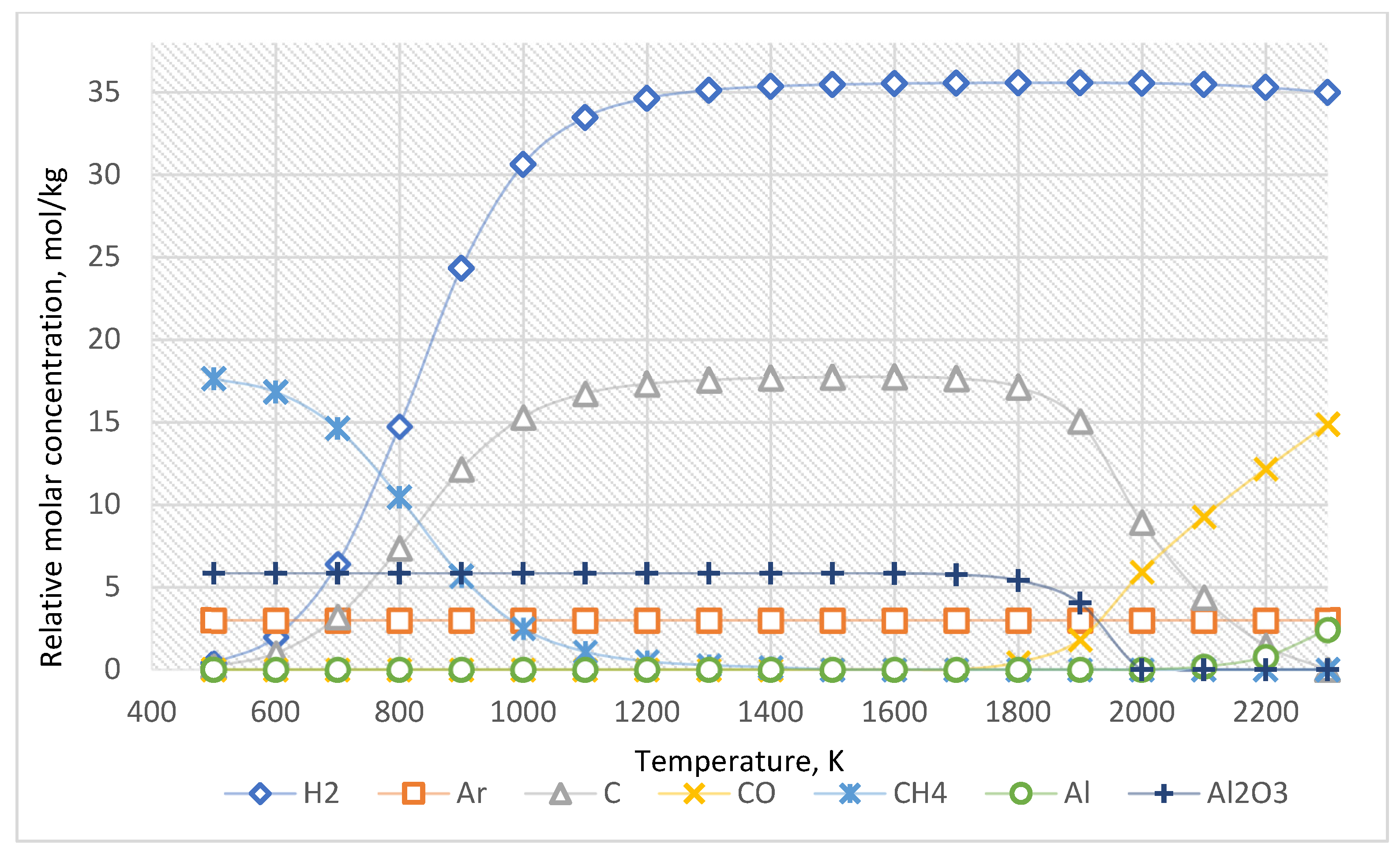
The equilibrium curves of the system “Al2O3:CH4:Ar = 1:3:0.5” are presented in Figure 5. The equilibrium composition of this system is presented in Table 4.
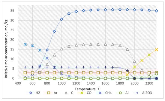
Figure 5.
The equilibrium curves of this system “Al2O3:CH4:Ar = 1:3:0.5”.
Table 4.
The equilibrium composition of the system “Al2O3:CH4: Ar = 1:3:0.5”, mol/kg.
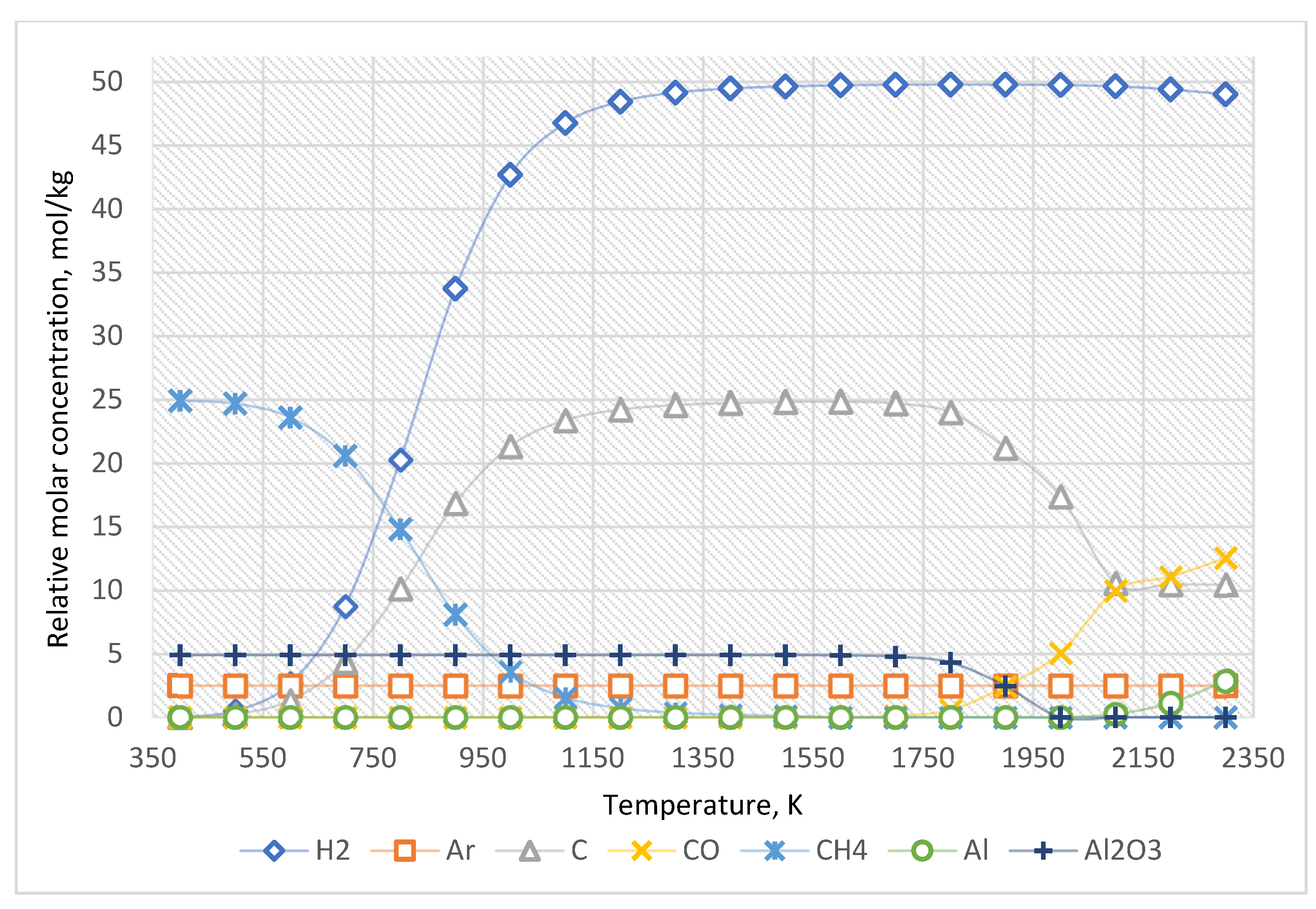
The equilibrium curves of the system “Al2O3:CH4:Ar = 1:5:0.5” are presented in Figure 6, and the equilibrium composition—is in Table 5.
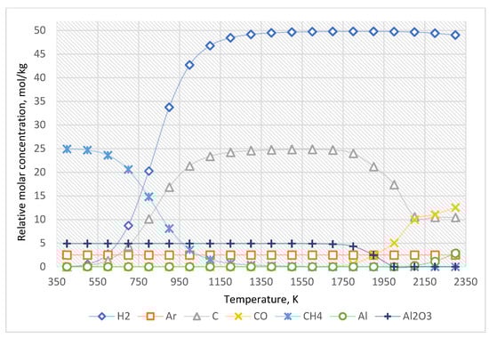
Figure 6.
The equilibrium curves of this system “Al2O3:CH4:Ar = 1:5:0.5”.
Table 5.
The equilibrium composition of the system “Al2O3:CH4: Ar = 1:5:0.5”, mol/kg.
The above measurements were also realized using certified measuring equipment at the Gas Institute and the Institute of NPP Safety Problems of the National Academy of Sciences of Ukraine.
As shown in Figure 6 and Table 5, the increased concentration of methane leads only to an increase in the amount of generated carbon and hydrogen.
The fundamental reactions are as follows:
CH4 + Al2O3 → C + 2H2 + Al2O3, under T = 600–1500 K;
3CH4 + Al2O3 → 2Al +6H2 + 3CO, under T = 1500–2300 K.
The left side of these equations shows the substance on which Al2O3 coating is applied and the substance whose decomposition products form the granule’s surface coating. The right part shows the substances formed during the pyrolysis of methane on the surface of Al2O3 according to the composition, mass, and energy conservation laws [33].
Therefore, an increased CH4 concentration leads to increased carbon and hydrogen formed when the temperature rises from 600 K. In this system, Al2O3 molecules are stable up to 1500 K. However, above 1500 K, carbon from methane reduces Al2O3 to Al with the formation of CO.
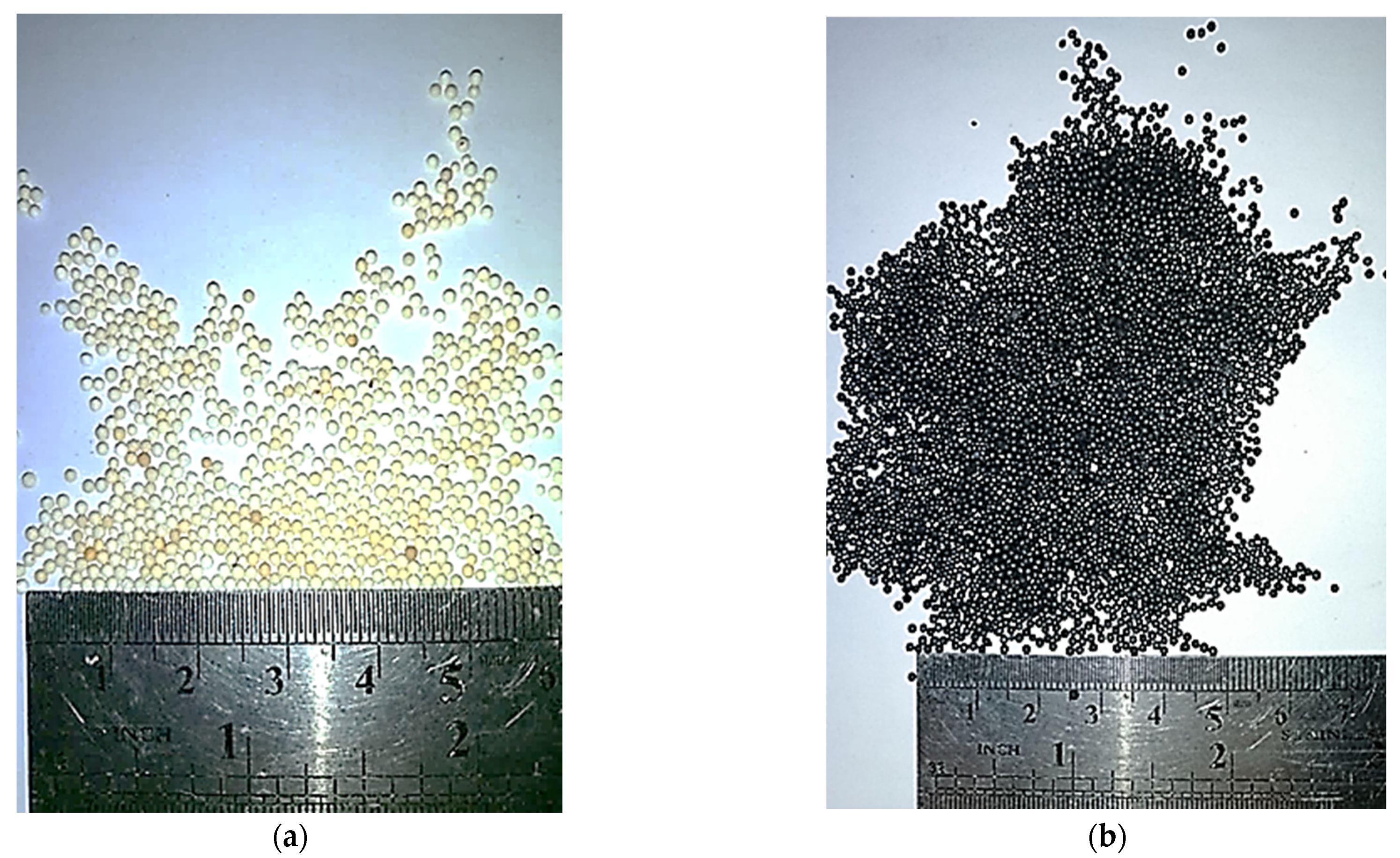
As a result of the conducted experimental research, it was possible to obtain a layer of a pyrocarbon coating on the model of microspherical nuclear fuel (granulated Al2O3) (Figure 7). The pyrocarbon content is 8% mass. The pyrocarbon coating was applied to Al2O3 granules with a 0.75–1.0 mm dispersity range.
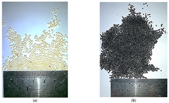
Figure 7.
Untreated (a) and treated (b) granules of Al2O3.
Figure 7 shows that the pyrocarbon densely covers the surface of Al2O3 granules. This indicates sufficient pyrocarbon coating on the granules and opens the prospect of implementing the pebble fuel elements in power reactors.
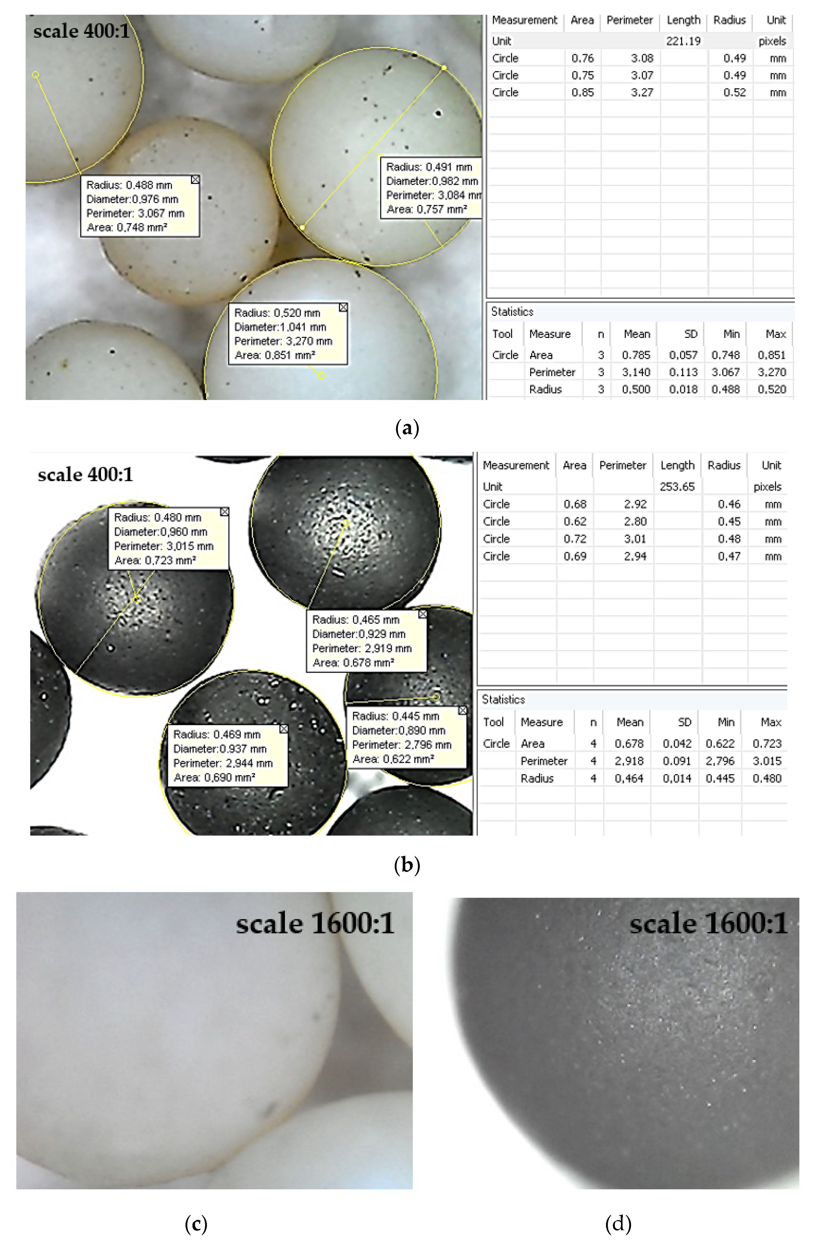
A comparison of the untreated and treated surfaces of granulated Al2O3 is presented in Figure 8.
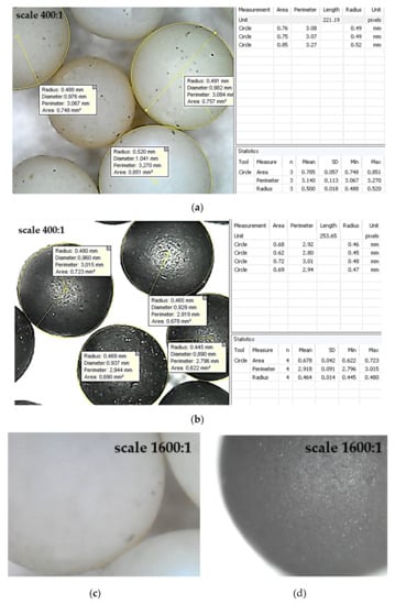
Figure 8.
Surfaces of the untreated (a,c) and treated (b,d) granules: (a,b)—×400; (c,d)—×1600.
According to Equation (3), for the mass fraction of X = (95 ± 1)%, the thickness of the pyrocarbon coating has been evaluated in a range of 14–21 μm.
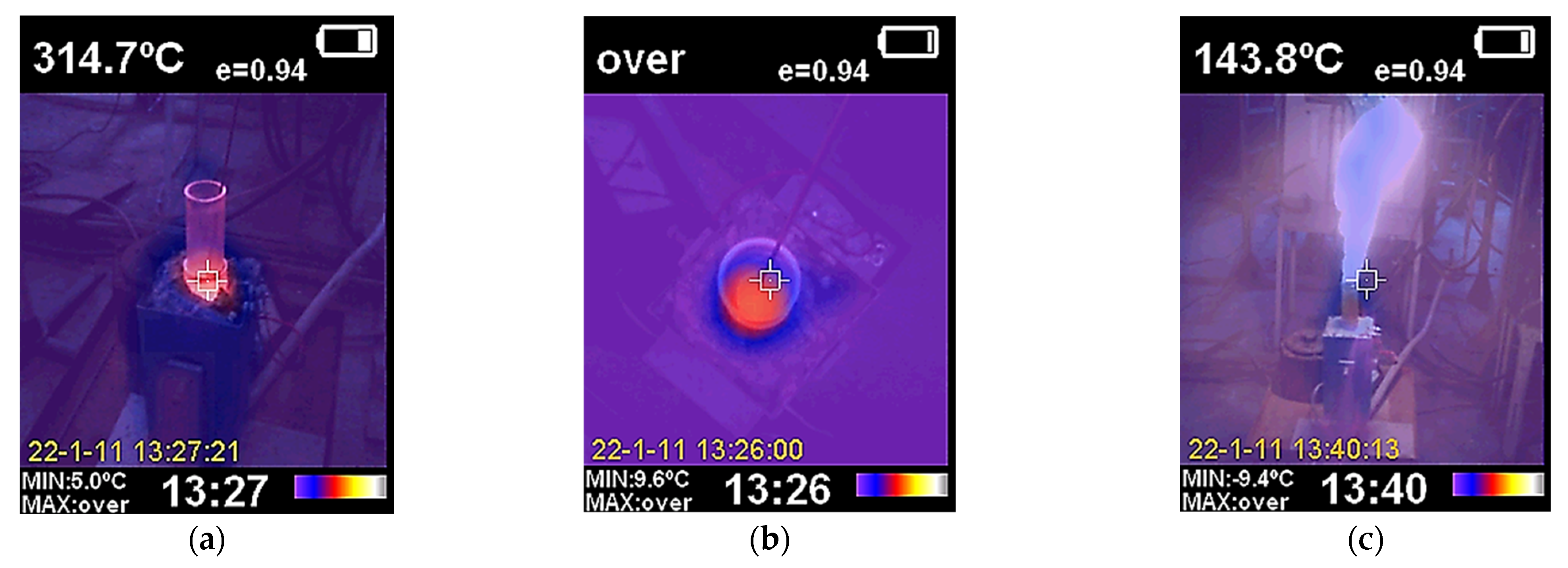
The results of the thermal imaging studies of the pyrolysis process are shown in Figure 9. According to the thermal imaging data, the most significant heat loss occurs through the upper part of the reactor near the gas outlet.

Figure 9.
Thermal imaging study of the installation heating for the supply of pure nitrogen (a,b) and a mixture of natural gas and nitrogen (c): (a,c)—side view; (b)—top view.
4. Discussion
As the thermodynamic calculations show (Figure 3, Table 2), methane decomposes into hydrogen and carbon starting at 600 K. As the temperature increases, the yield of carbon and hydrogen increases. Initially, carbon is deposited as ash and pyrocarbon, acting as a reducing agent. In this system, a molecule of Al2O3 is stable until the temperature of 1500 K. If temperatures exceed 1500 K, the carbon formed from methane begins to recover Al2O3 to Al with the formation of CO. Therefore, the Al2O3 content slightly decreases in the 1500–1900 K temperature range. However, above 2000 K, the Al2O3 content decreases significantly and approaches zero. The Al content increases above 2000 K. Moreover, at temperatures above 2100 K, the concentration of atomic hydrogen formation increases. This result corresponds to the fact that atomic hydrogen is released only in cases without an inert medium. The formation of molecules H2 from atomic hydrogen is significantly affected by impurities in the gas. In other words, in the presence of inert gas in the system, the formation of atomic hydrogen is observed in the initial stage. Nevertheless, then gas molecules H2 are formed. In contrast, for multicomponent systems with noninert components, the formation of H2 occurs immediately. This explains the difference in data presented in Table 2, Table 3, Table 4 and Table 5.
These results demonstrate the potentially better realization of processing methods for coated granular materials for nuclear reactors compared with another study [34], where fuels containing either uncoated or carbon-coated particles were first burned in oxygen at 800–1200 °C to eliminate the graphite and convert the uranium, thorium, and other metallic constituents of the fuel to their respective oxides.
Remarkably, adding an inert environment to the system (e.g., nitrogen) is recommended to avoid intensive ash formation during the pyrolysis of hydrocarbon gases. The main results also correspond to the recent development of spherical pyrolytic-carbon-coated UC2 and UThC2 fuel particles [35].
According to the evaluated data (Figure 4, Table 3), before the temperature of 1500 K, nitrogen does not significantly affect the target reaction products. Nevertheless, if the temperature exceeds 1500 K, the formation of various nitrogen-containing compounds with carbon and hydrogen is possible in the system. The reduction of Al2O3 to Al when nitrogen is added to the system occurs at a slightly higher temperature (over 2100 K).
Reactions (2) and (3) also correspond to fundamentals of catalytic decomposition [36].
Adding another inert environment (argon) allows for avoiding the formation of the compounds mentioned above. The results of the thermodynamic calculations (Figure 5, Table 4) indicate that argon does not affect the chemistry of the process.
According to the thermodynamic calculations, it can be concluded that the rational conditions for the pyrocarbon coating at the pressure of 0.1 MPa are realized at a temperature of 900–1500 K and using argon as an inert environment.
The obtained results could also be helpful for further developments within interdisciplinary research on carbon coatings [37], understanding the interdiffusion behavior of coated materials [38] and restraining the interdiffusion of coated materials in the high-temperature environment [39].
Further research will be aimed at the experimental study of the impact of argon supply on applying pyrocarbon coatings on granules of Al2O3 in an electrothermal fluidized bed. A more precise study of the impact of operating parameters on the thickness, as well as the physical and chemical properties of the resulting coating, will also be carried out further using an electron microscope.
5. Conclusions
Based on thermodynamic calculations, possible chemical interactions have been determined when applying a protective pyrocarbon coating to the microspherical nuclear fuel model Al2O3, that is, carbon formation from methane and chemical resistance of Al2O3 before interaction with hydrogen and carbon up to 1500 K. In the case of an electrothermal fluidized bed, the following rational process parameters have been evaluated: temperature of 900–1500 K and pressure of 0.1 MPa.
Practically, from the designed experimental standpoint, the possibility of applying the pyrocarbon coating on the model of pebble nuclear fuel has been proven. In this case, during pyrolysis, pyrocarbon is precipitated from hydrocarbon in a reactor with an electrothermal fluidized bed at a temperature in the bed in the range of 1073–1273 K.
Also, it has been experimentally proven that the pyrocarbon film evenly covers the granules’ entire surface. This fact proves the technological conditions to produce pebble nuclear fuel.
Overall, thermodynamic calculations showed the need to add an inert medium (nitrogen or argon) to the reactor. This gas significantly reduces the carbon black formation (with amorphous morphology), which pollutes the reaction zone and reduces the efficiency of using raw natural gas.
Author Contributions
Conceptualization, V.S. (Vsevolod Sklabinskyi) and O.L.; methodology, K.S. and M.S.; software, J.P. and I.P.; validation, R.O., M.Y. and O.M.; formal analysis, V.S. (Vitalii Storozhenko), I.P. and J.P.; investigation, M.S., O.L. and K.S.; resources, V.S. (Vsevolod Sklabinskyi), R.O. and O.M.; data curation, M.Y. and V.S. (Vitalii Storozhenko); writing—original draft preparation, V.S. (Vsevolod Sklabinskyi), M.S., K.S. and O.L.; writing—review and editing, I.P., J.P. and V.S. (Vitalii Storozhenko); visualization, O.M., R.O. and M.Y.; supervision, O.L.; project administration, V.S. (Vsevolod Sklabinskyi); funding acquisition, J.P. All authors have read and agreed to the published version of the manuscript.
Funding
This work was supported by the Slovak Research and Development Agency, under the contract No. APVV-15-0602; and by the projects VEGA 1/0704/22, KEGA 022TUKE-4/2023, granted by the Ministry of Education, Science, Research and Sport of the Slovak Republic.
Institutional Review Board Statement
Not applicable.
Informed Consent Statement
Not applicable.
Data Availability Statement
Data are available on request from the authors.
Acknowledgments
The scientific results were achieved within the project “Creation of new granular materials for nuclear fuel and catalysts in the active hydrodynamic environment” (State reg. No. 0120U102036) ordered by the Ministry of Education and Science of Ukraine.
Conflicts of Interest
The authors declare no conflict of interest.
Nomenclature
| Abbreviations | |
| HTGR | high-temperature gas-cooled reactor; |
| NPP | nuclear power plant. |
| Symbols | |
| d | diameter of granules, m |
| h | thickness of the pyrocarbon coating, m |
| m1 | the mass of batches of granules before coating, kg |
| m2 | the mass of batches of granules after coating, kg; |
| X | the mass fraction of pyrocarbon coating, % |
| ρ0 | density of Al2O3 granules, kg/m3 |
| ρc | density of pyrocarbon coating, kg/m3 |
References
- Cao, J.; Cohen, A.; Hansen, J.; Lester, R.; Peterson, P.; Xu, H. China-U.S. cooperation to advance nuclear power. Science 2016, 353, 547–548. [Google Scholar] [CrossRef] [PubMed]
- Kalinowski, B.; Włodarski, R.; Szterk, L. Studies on Obtaining Pyrocarbon Coatings on Spherical Particles of Uranium Materials. Report “P”—No. 1631/IV/C. Polish–Italian Seminar of Some Chemical, Ceramic and Metallurgical Aspects of Nuclear Fuels; Institute of Nuclear Research: Zakopane, Poland, 1971. [Google Scholar]
- Long, E.L.; Tiegs, T.N.; Robbins, J.M.; Kania, M.J. Performance of HTGR Fertile Particles Irradiated in HFIR Capsule HT-32. Contract No. W-7405-eng-26. Metals and Ceramics Division. HTGR Base Technology Program. Fueled Graphite Development (189a 01330); Oak Ridge National Laboratory: Oak Ridge, TN, USA, 1980. [Google Scholar]
- Tepest, P.A. A direct measurement of bacon anisotropy factors on pyrocarbon coatings deposited on fuel particles for the high temperature reactor. Carbon 1978, 16, 171–174. [Google Scholar] [CrossRef]
- Y Leon, S.B.; Lindberg, J.C.H. The Humanitarian Atom: The Role of Nuclear Power in Addressing the United Nations Sustainable Development Goals. In Nuclear Law; T.M.C. Asser Press: Hague, The Netherlands, 2022; pp. 71–298. [Google Scholar] [CrossRef]
- Kerlin, T.W.; Upadhyaya, B.R. Dynamics and Control of Nuclear Reactors; Academic Press: Cambridge, MA, USA, 2019. [Google Scholar] [CrossRef]
- Chen, F.; Han, Z. Steady-state thermal fluids analysis for the HTR-PM equilibrium core. Int. J. Adv. Nucl. React. Des. Technol. 2021, 3, 11–17. [Google Scholar] [CrossRef]
- Knol, S.; De Groot, S.; Salama, R.V.; Best, J.; Bakker, K.; Bobeldijk, I.; Westlake, J.R.; Fütterer, M.A.; Laurie, M.; Tang, C.; et al. HTR-PM fuel pebble irradiation qualification in the high flux reactor in Petten. Nucl. Eng. Des. 2018, 329, 82–88. [Google Scholar] [CrossRef]
- Pratama, A.L.; Irwanto, D. Study on fissile material usage for 50 MWt high temperature gas reactor using (Pu-U)O2 fuel. J. Phys. Conf. Ser. 2021, 1772, 012004. [Google Scholar] [CrossRef]
- Horvath, A.; Rachlew, E. Nuclear power in the 21st century: Challenges and possibilities. Ambio 2016, 45, 38–49. [Google Scholar] [CrossRef]
- Taryo, T. The development of HTGR-TRISO coated fuels in the globe: Challenging of Indonesia to be an HTGR fuel producer. J. Phys. Conf. Ser. 2019, 1198, 022062. [Google Scholar] [CrossRef]
- Ivanov, A.S.; Rusinkevich, A.A. The kinetics of fission products release from microfuel taking into account the trapped fraction and limited solubility effects. Nucl. Eng. Des. 2016, 306, 47–51. [Google Scholar] [CrossRef]
- Ivanov, A.S.; Rusinkevich, A.A.; Taran, M.D. The “trapped fraction” and interfacial jumps of concentration in fission products release from coated fuel particles. J. Nucl. Mater. 2018, 498, 395–399. [Google Scholar] [CrossRef]
- Ivanov, A.S.; Rusinkevich, A.A.; Taran, M.D. Simulation of fission product release from microfuel particles taking into account the effects of trapped fraction and concentration jumps at the interfaces. Phys. At. Nucl. 2019, 82, 1214–1218. [Google Scholar] [CrossRef]
- Roos, E.; Maile, K.; Berreth, K.; Lyutovich, A.; Weiss, R.; Perova, T.; Moore, A. Chemical vapour deposition of PyC–SixCy–SiC–Si3N4 multilayer with graded C…SiC transition. Surf. Coat. Technol. 2004, 180–181, 465–469. [Google Scholar] [CrossRef]
- Liu, N.; Guo, L.; Kou, G.; Li, Y.; Yin, X. Carbon nanotube reinforced pyrocarbon matrix composites with high coefficient of thermal expansion for self-adapting ultra-high-temperature ceramic coatings. Ceram. Int. 2022, 48, 15668–15676. [Google Scholar] [CrossRef]
- Xu, M.; Guo, L.; Fu, Y. Effect of pyrocarbon texture on the mechanical and oxidative erosion property of SiC coating for protecting carbon/carbon composites. Ceram. Int. 2021, 47, 32657–32665. [Google Scholar] [CrossRef]
- Xu, M.; Guo, L.; Huang, J.; Zhang, P. Microstructure and resistance to thermal shock of SiC coatings that are prepared on C/C-composite pyrocarbon matrices of various textures. Ceram. Int. 2021, 47, 9818–9826. [Google Scholar] [CrossRef]
- Duan, H.; Zhang, Z.; Li, L.; Li, W. Effect of pyrocarbon interphase texture and thickness on tensile damage and fracture in T-700™ carbon fiber–reinforced silicon carbide minicomposites. J. Am. Ceram. Soc. 2021, 3, 2171–2181. [Google Scholar] [CrossRef]
- Chernikov, A.S. HTGR fuel and fuel elements. Energy 1991, 16, 263–274. [Google Scholar] [CrossRef]
- López-Honorato, E.; Meadows, P.J.; Xiao, P.; Marsh, G.; Abram, T.J. Structure and mechanical properties of pyrolytic carbon produced by fluidized bed chemical vapor deposition. Nucl. Eng. Des. 2008, 238, 3121–3128. [Google Scholar] [CrossRef]
- Xu, J.; Guo, L.; Wang, H.; Li, K.; Wang, T.; Li, W. Mechanical property and toughening mechanism of 2.5D C/C-SiC composites with high textured pyrocarbon interface. Ceram. Int. 2021, 47, 29183–29190. [Google Scholar] [CrossRef]
- Kurbakov, S.D. Formation of multifunctional barriers to increase the radiochemical resistance of the protective coatings of HTGR fuel elements. At. Energy 2009, 106, 377–388. [Google Scholar] [CrossRef]
- Ilinich, G.N.; Kvon, R.I.; Ayupov, A.B.; Chumachenko, V.A.; Romanenko, A.V. Mesoporous alumina infiltrated with a very thin and complete carbon layer. Microporous Mesoporous Mater. 2015, 208, 120–128. [Google Scholar] [CrossRef]
- Opyatyuk, V.V.; Kozlov, I.L.; Karchev, K.D.; Vistiak, S.V.; Kozlov, O.I.; Turmanidze, R. Simulation of point defects formation in the fuel element of a nuclear power plant’s wave reactor. J. Eng. Sci. 2023, 10, F7–F10. [Google Scholar] [CrossRef]
- Yang, H.-C.; Park, H.-O.; Park, K.-T.; Kim, S.-J.; Kim, H.-J.; Eun, H.-C.; Lee, K. Development of carbonization and a relatively high-temperature halogenation process for the removal of radionuclides from spent ion exchange resins. Processes 2001, 9, 96. [Google Scholar] [CrossRef]
- Yang, H.-C.; Lee, M.-W.; Eun, H.-C.; Kim, H.-J.; Lee, K.; Seo, B.-K. Thermal decontamination of spent activated carbon contaminated with radiocarbon and tritium. Processes 2020, 8, 1359. [Google Scholar] [CrossRef]
- Li, Z.; Wang, J.; Huang, J.; Ding, M. Development and research of triangle-filter convolution neural network for fuel reloading optimization of block-type HTGRs. Appl. Soft Comput. 2023, 136, 110126. [Google Scholar] [CrossRef]
- Semeiko, K.V.; Kustovskyi, S.S.; Kupriyanchuk, S.V.; Chumak, R.E. Dependence of the pyrocarbon structure on the parameters of the process of pyrolysis of hydrocarbon gases in an electrothermal fluidized bed. J. Eng. Phys. Thermophys. 2020, 93, 677–684. [Google Scholar] [CrossRef]
- Meshcheryakov, E.P.; Reshetnikov, S.I.; Sandu, M.P.; Knyazev, A.S.; Kurzina, I.A. Efficient adsorbent-desiccant based on aluminium oxide. Appl. Sci. 2021, 11, 2457. [Google Scholar] [CrossRef]
- Attard, P. Entropy beyond the Second Law (Second Edition): Thermodynamics and Statistical Mechanics for Equilibrium, Non-Equilibrium, Classical, and Quantum Systems; IOP Publishing Ltd.: Bristol, UK, 2023; pp. 1–61. [Google Scholar] [CrossRef]
- Pelton, A.D. Thermodynamics and Phase Diagrams of Materials. Materials Science and Technology; Wiley Online Library: Hoboken, NJ, USA, 2013. [Google Scholar] [CrossRef]
- Fau, G.; Gascoin, N.; Steelant, J. Hydrocarbon pyrolysis with a methane focus: A review on the catalytic effect and the coke production. J. Anal. Appl. Pyrolysis 2014, 108, 1–11. [Google Scholar] [CrossRef]
- Blanco, R.E.; Cathers, G.I.; Ferris, L.M.; Gens, T.A.; Horton, R.W.; Nicholson, E.L. Processing of graphite reactor fuels containing coated particles and ceramics. Nucl. Sci. Eng. 2017, 20, 1964. [Google Scholar] [CrossRef]
- Sowman, H.G.; Surver, R.L.; Johnson, J.R. The development of spherical pyrolytic-carbon-coated UC2 and UThC2 fuel particles. Nucl. Sci. Eng. 2017, 20, 1964. [Google Scholar] [CrossRef]
- Ashok, J.; Raju, G.; Reddy, P.S.; Subrahmanyam, M.; Venugopal, A. Catalytic decomposition of CH4 over NiO-Al2O3-SiO2 catalysts: Influence of catalyst preparation conditions on the production of H2. Int. J. Hydrog. Energy 2008, 33, 4809–4818. [Google Scholar] [CrossRef]
- Guan, Z.; Zou, K.; Wang, X.; Deng, Y.; Chen, G. The synergistic effect of P-doping and carbon coating for boosting electrochemical performance of TiO2 nanospheres for sodium-ion batteries. Chin. Chem. Lett. 2021, 32, 3847–3851. [Google Scholar] [CrossRef]
- Yang, J.; Bai, S.; Sun, J.; Wu, H.; Sun, S.; Wang, S.; Li, Y.; Ma, W.; Tang, X.; Xu, D. Microstructural understanding of the oxidation behavior of cr-coated alloy 800H in supercritical water. Corros. Sci. 2023, 211, 110910. [Google Scholar] [CrossRef]
- Yang, J.; Shang, L.; Sun, J.; Bai, S.; Wang, S.; Liu, J.; Yun, D.; Ma, D. Restraining the cr-zr interdiffusion of Cr-coated Zr alloys in high temperature environment: A Cr/CrN/Cr coating approach. Corros. Sci. 2023, 214, 111015. [Google Scholar] [CrossRef]
Disclaimer/Publisher’s Note: The statements, opinions and data contained in all publications are solely those of the individual author(s) and contributor(s) and not of MDPI and/or the editor(s). MDPI and/or the editor(s) disclaim responsibility for any injury to people or property resulting from any ideas, methods, instructions or products referred to in the content. |
© 2023 by the authors. Licensee MDPI, Basel, Switzerland. This article is an open access article distributed under the terms and conditions of the Creative Commons Attribution (CC BY) license (https://creativecommons.org/licenses/by/4.0/).