
Effect of Sealing Treatment on Corrosion Resistance of Arc-Sprayed Zn and Zn85-Al15 Coatings


Abstract
:1. Introduction
2. Materials and Methods
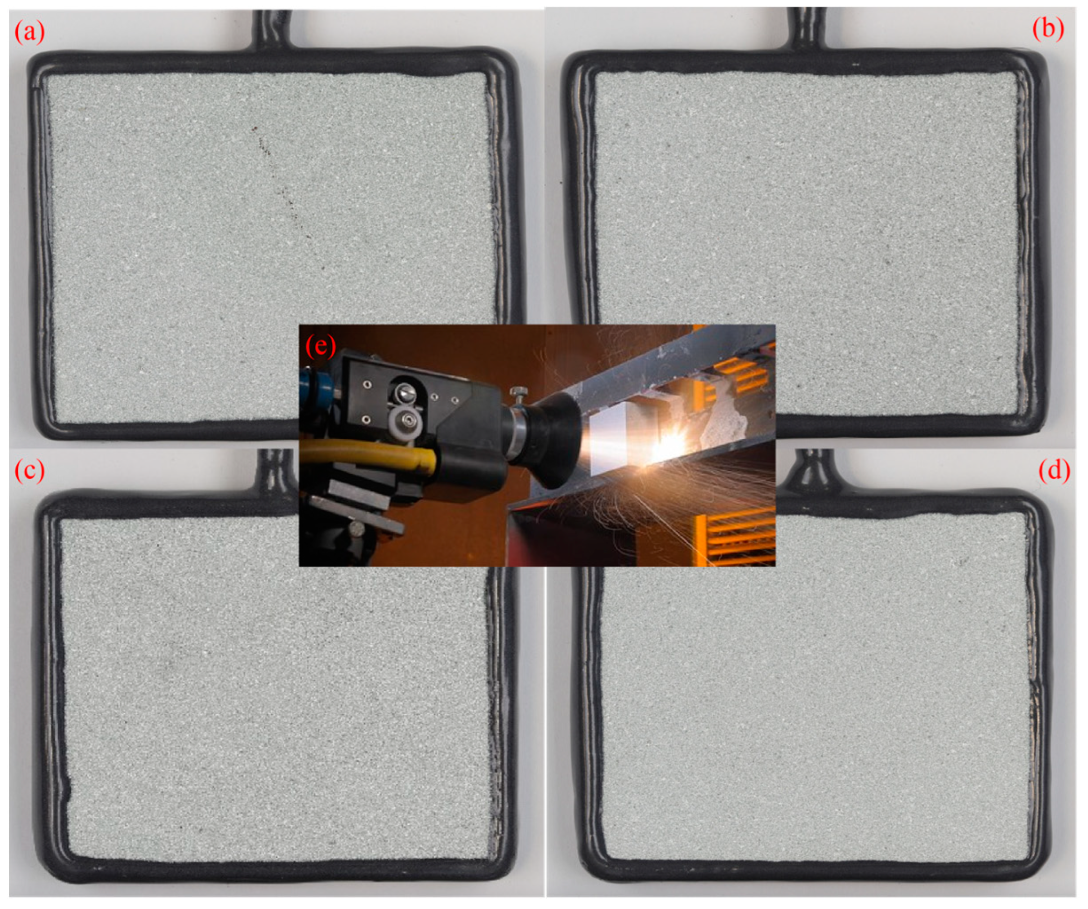
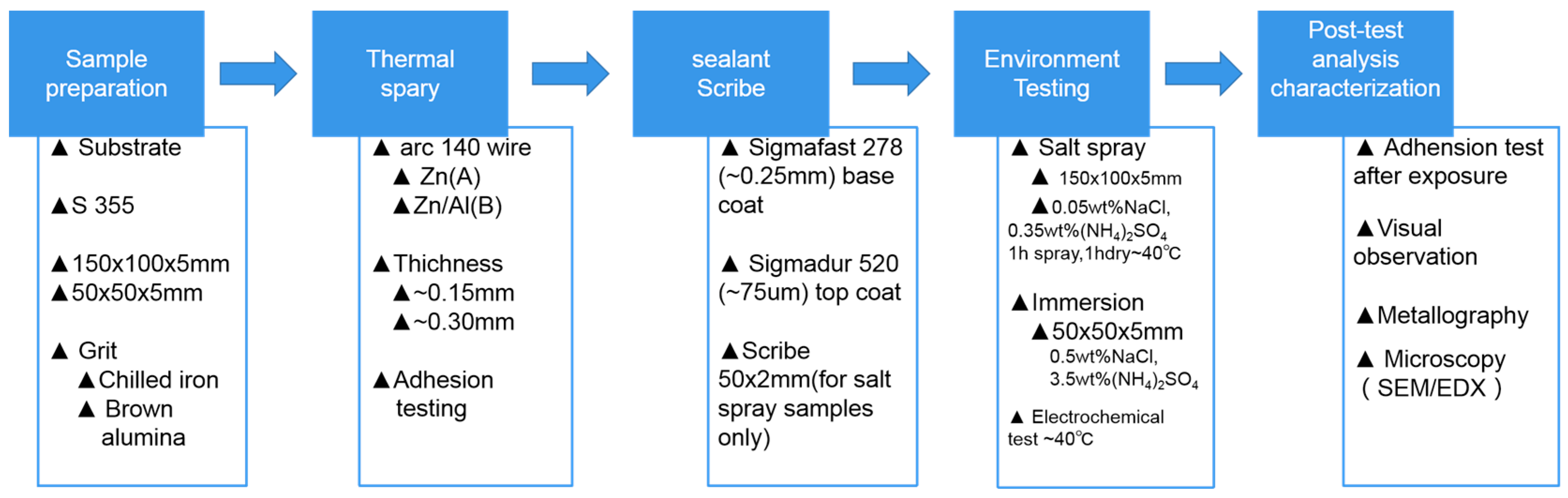
2.1. Sample Preparation
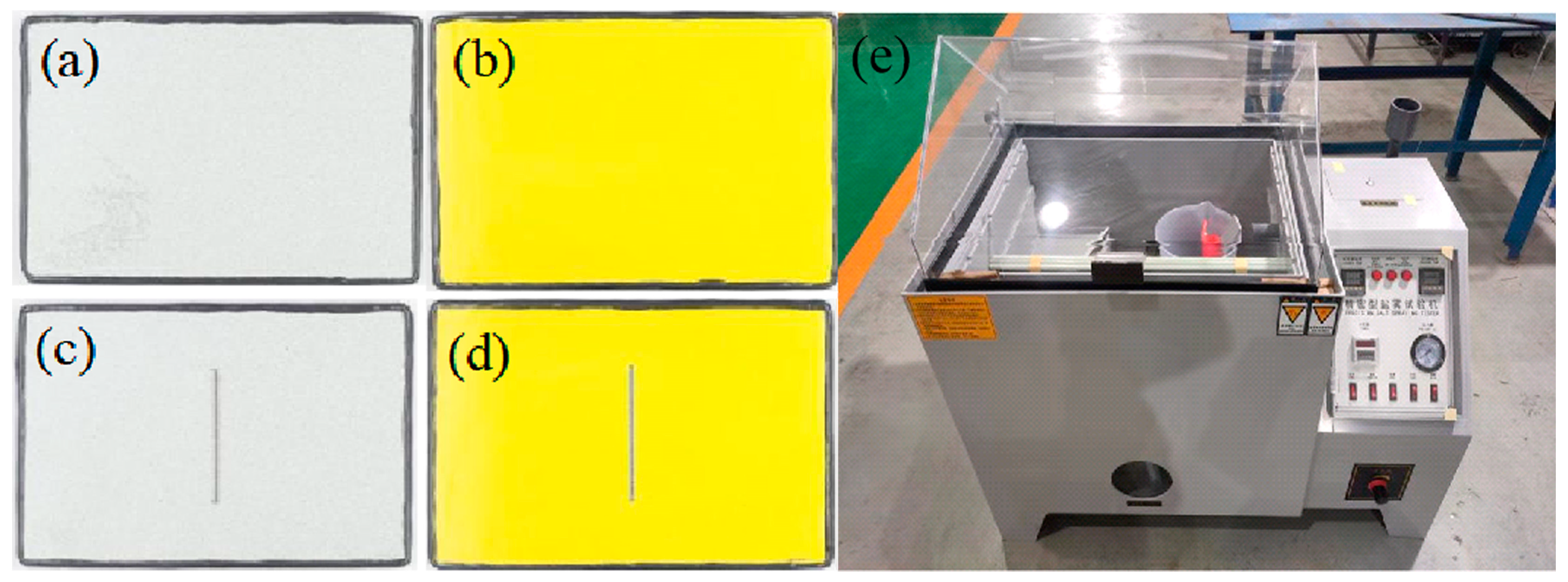
2.2. Salt Spray Test
2.3. Immersion Test
2.4. Post-Test Analysis and Characterization
3. Results and Discussions
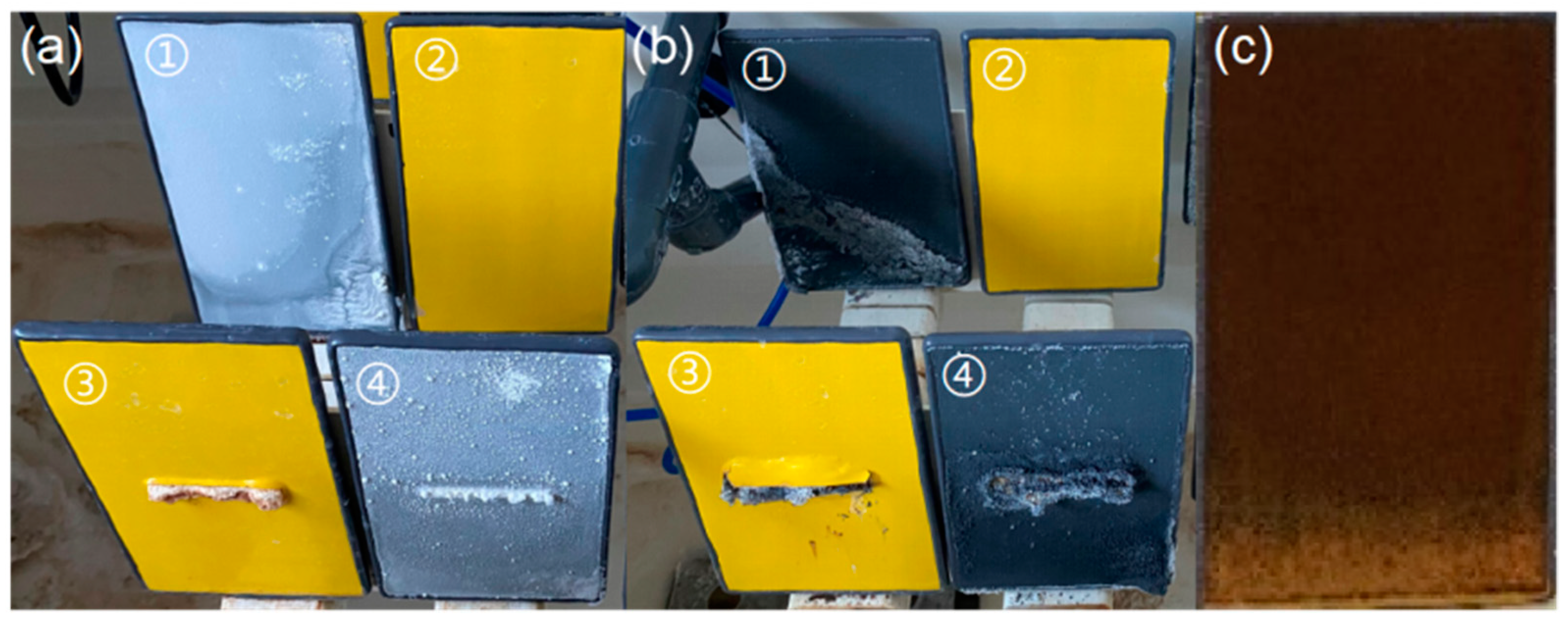
3.1. Macroscopic Morphology Analysis
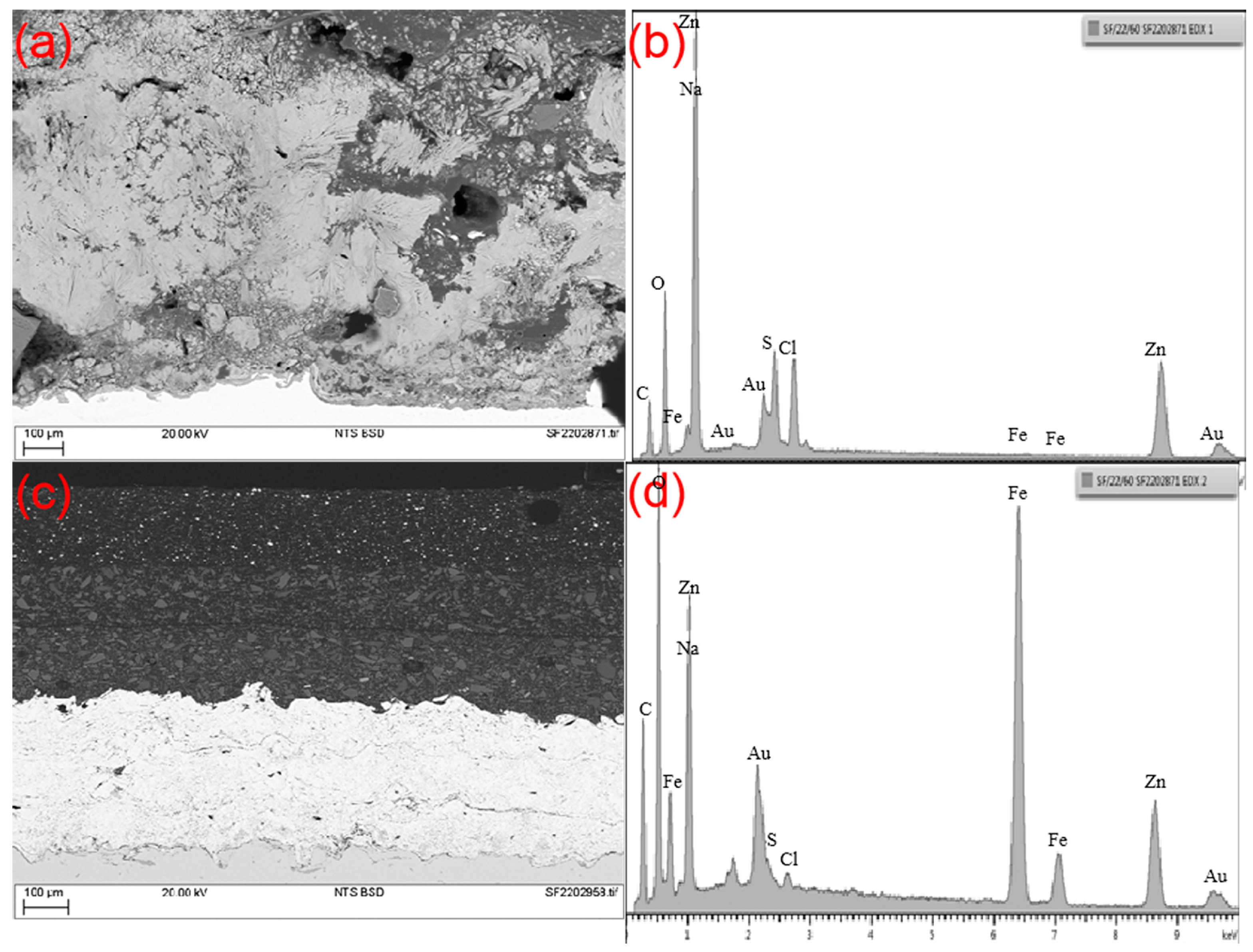
3.2. Microscopic Morphology Analysis
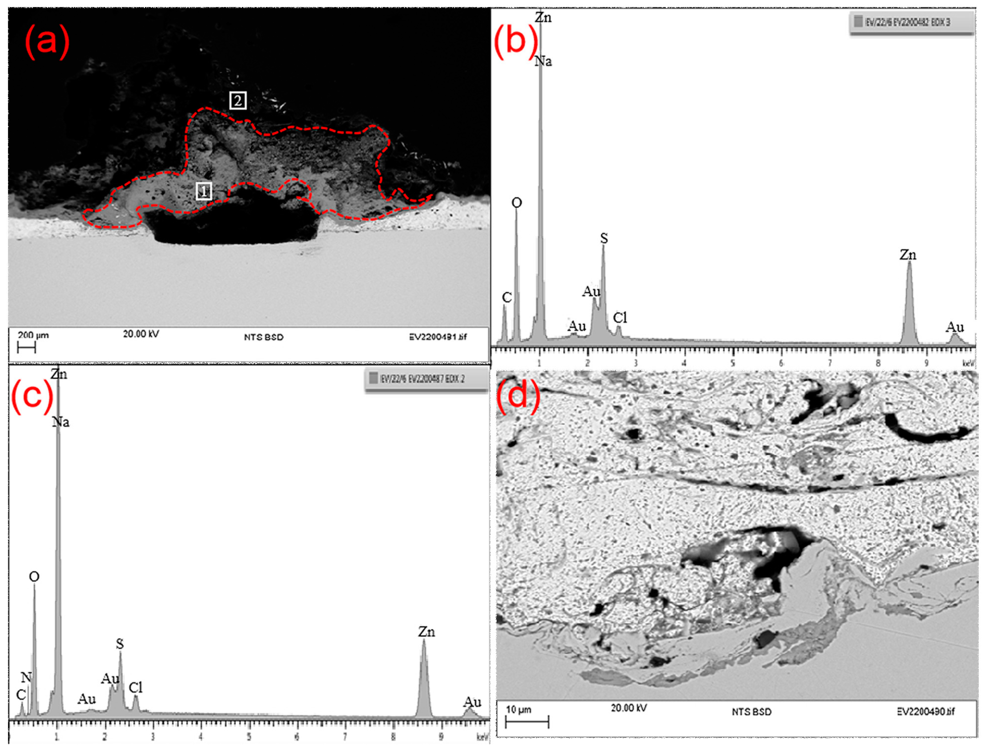
3.2.1. Microstructure of the Zn Coating
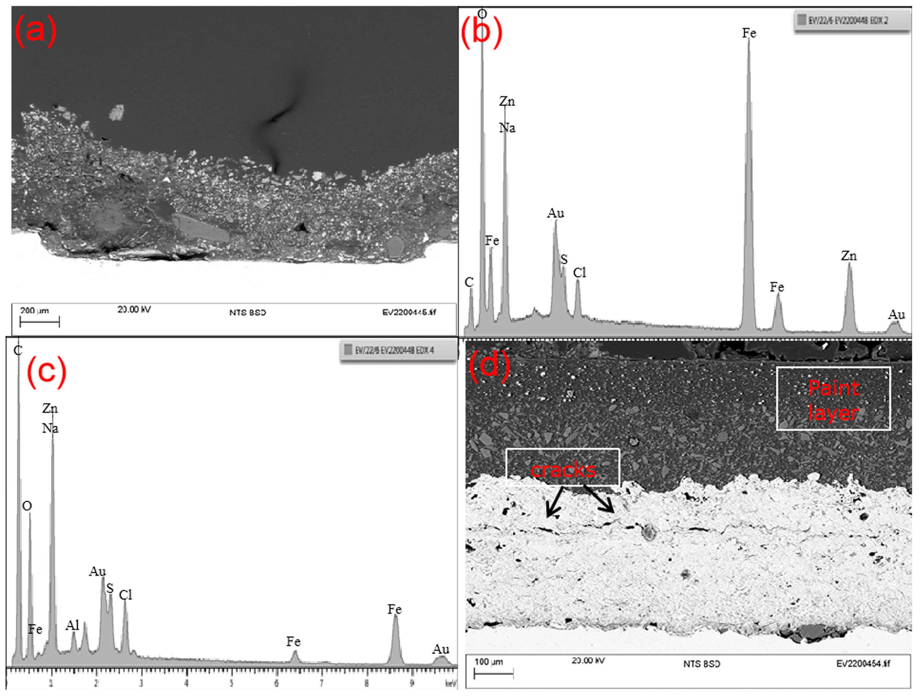
3.2.2. Microstructure of the Zn-Al Coating
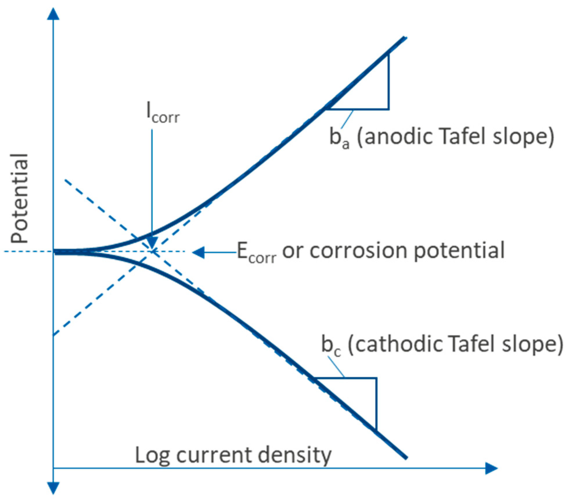
3.3. Full Immersion and Electrochemical Monitoring
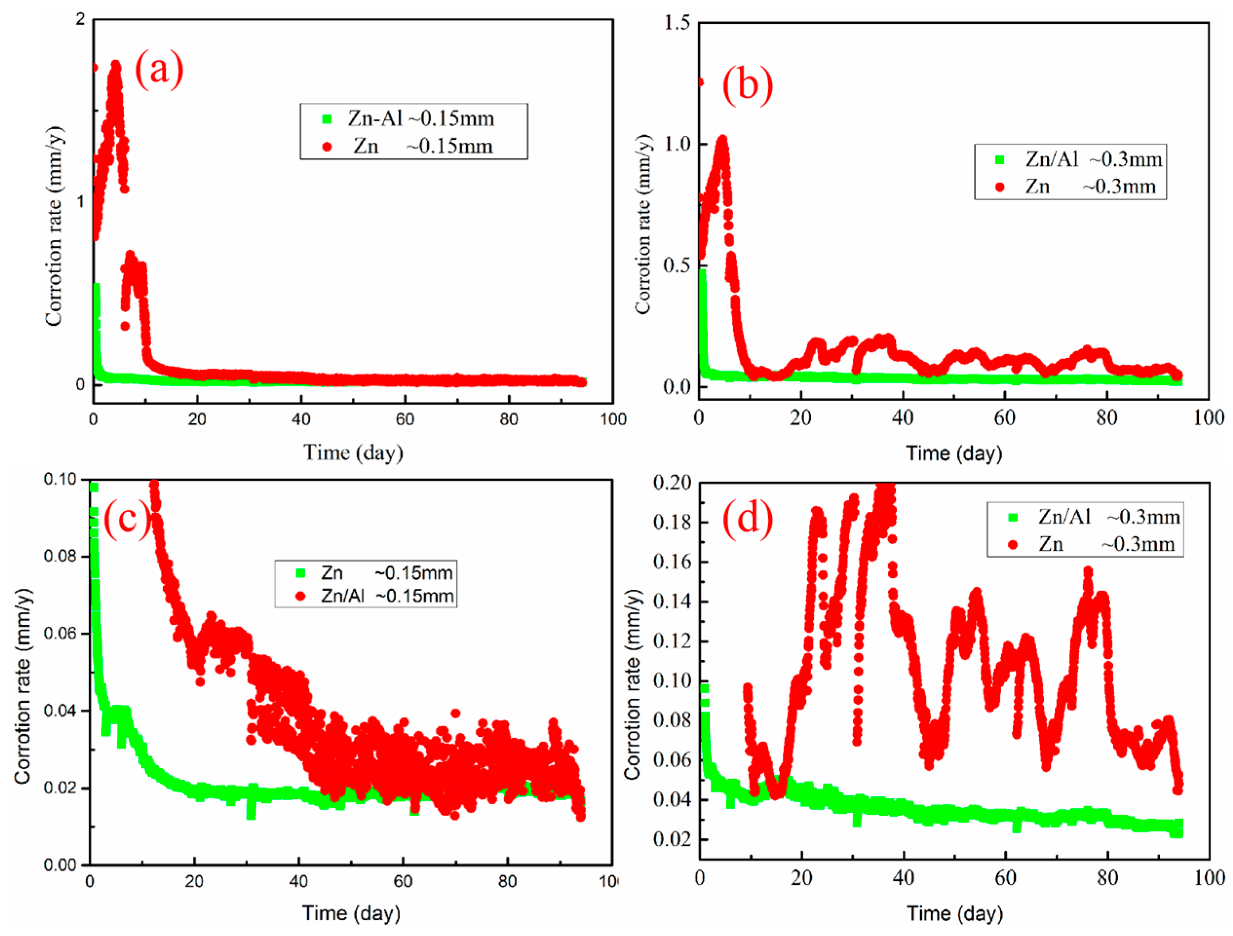
3.4. Corrosion Rate
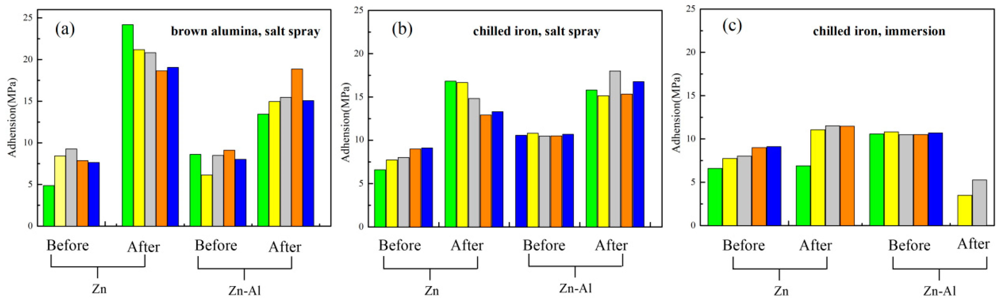
3.5. Adhesion Test
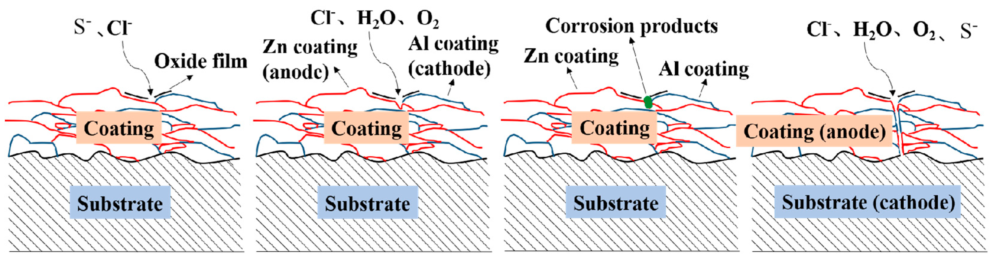
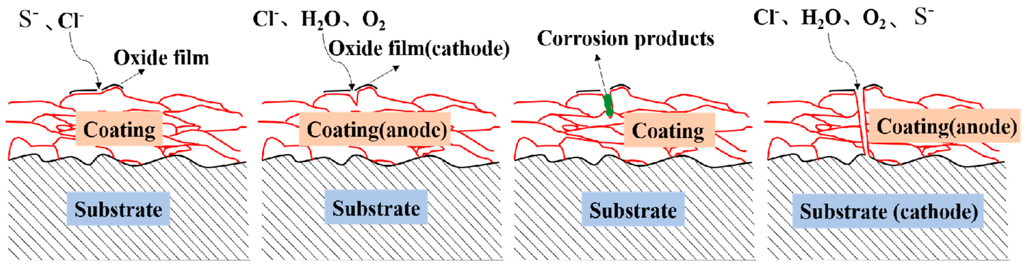
3.6. Corrosion Mechanism
4. Conclusions
- (1)
- After sealing treatment, the defect-free Zn and defect-free Zn-Al coatings have a good application prospect in corrosive environments. After the corrosion of the coating, the corrosion mechanisms of the two coatings are similar in the earlier stage, and the corrosion products of the Zn-Al coating block the corrosion channel in the later stage, resulting in a decrease in the corrosion rate.
- (2)
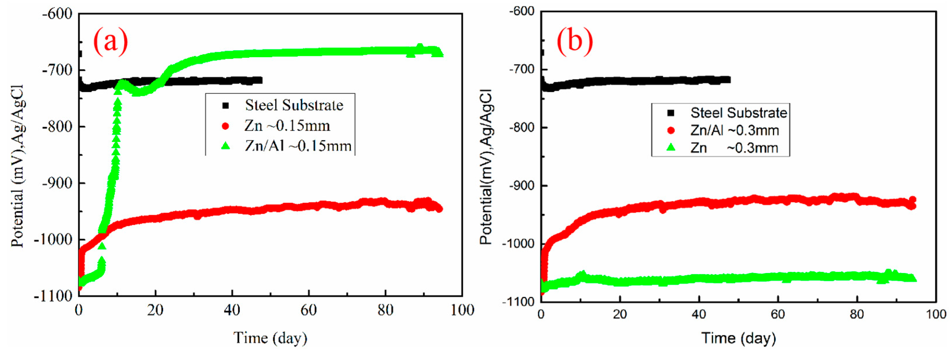
- The corrosion resistance of Zn coatings is positively correlated with the coating thickness, while that of Zn/Al coatings is not. After 90 days of immersion, the OCP of 0.15 mm Zn coating is about −670 mV and that of 0.3 mm Zn coating is about −1050 mV, while the OCP of Zn-Al coating is more stable at about −950 mV.
- (3)
- The corrosion rate of Zn85/Al15 coating at 300 μm is about 0.03 mm/y, and the corrosion rate of Zn coating is higher than Zn85/Al15 coating and is unstable.
- (4)
- The Zn-Al coating exhibits good bonding strength with the substrate in salt spray and immersion medium. The Zn coatings prepared on steel blasted with brown alumina and chilled iron showed adhesion values of ~21 MPa and ~15 MPa, respectively.
- (5)
- In general, the protection effect of the coating on the steel substrate can be significantly enhanced by painting the surface of the Zn-Al coating. It provides good protection, even if there are defects. The long service life of the matrix steel can be realized by spraying the Zn-Al coating.
Author Contributions
Funding
Institutional Review Board Statement
Informed Consent Statement
Data Availability Statement
Conflicts of Interest
References
- López-Ortega, A.; Bayón, R.; Arana, J. Evaluation of Protective Coatings for Offshore Applications. Corrosion and Tribocorrosion Behavior in Synthetic Seawater. Surf. Coat. Technol. 2018, 349, 1083–1097. [Google Scholar] [CrossRef]
- Iannuzzi, M.; Barnoush, A.; Johnsen, R. Materials and Corrosion Trends in Offshore and Subsea Oil and Gas Production. NPJ Mater. Degrad. 2017, 11, 1–11. [Google Scholar] [CrossRef]
- Ann, K.Y.; Song, H.W. Chloride Threshold Level for Corrosion of Steel in Concrete. Corros. Sci. 2007, 4911, 4113–4133. [Google Scholar] [CrossRef]
- Liu, A.; Xiao, K.; Dong, C.F.; Wang, E.Q.; Xin, S.G. Corrosion resistance of three arc-sprayed zinc coatings in 3.5%NaCl Solution. Corros. Prot. 2012, 3304, 276–280. [Google Scholar]
- Liu, Y.D.; Zhou, Y.; Ma, X.L. Corrosion behaviors of several kinds of arc sprayed metal coatings in 3.5%NaCl solution. Surf. Technol. 2016, 4509, 71–75. [Google Scholar]
- Li, C.L. Preparation of Zn-Al Pseudo Alloy Coatings and Their Corrosion Resistance in Marine Environment; China University of Pet: Qingdao, China, 2010. [Google Scholar]
- Rodriguez, R.M.H.P.; Paredes, R.S.C.; Wido, S.H.; Calixto, A. Comparison of aluminum coatings deposited by flame spray and by electric arc spray. Surf. Coat. Technol. 2007, 2021, 172–179. [Google Scholar] [CrossRef]
- Liu, A.Q.; Xiao, K.; Lix, G.; Yuan, J.P. Research on accelerated test of simulated marine atmosphere corrosion of Zn and Zn-Al alloy coating. Therm. Pray Technol. 2016, 802, 36–42. [Google Scholar]
- Zhou, J.Q.; Qin, S.; Min, X.B.; Xia, G.M.; Zhang, Q.Q. Research on performance of thermal spraying Zn coating. Metal Mater. Metall. Eng. 2016, 4401, 13–19+57. [Google Scholar]
- Irving, B. Thermal-sprayed zinc coatings defend steel and concrete bridges. Weld. J. 1993, 729, 69–72. [Google Scholar]
- Zhang, Z.L. Application of thermal spraying technology for corrosion protection. Corros. Sci. Prot. Techno. 2000, 12, 354–358. [Google Scholar]
- Liu, Y.; Wei, S.C.; Wang, Y.J.; Xu, B.S. Corrosion resistance properties of zinc/aluminum based coating prepared by automatic high velocity arc spray. J. Funct. Mater. 2010, 41, 296–299. [Google Scholar]
- Wang, L.X.; Wang, J.J.; Qi, H.Q. Corrosion performance of arc-sprayed Zn coating in simulated acid rain environment. Weld. Join. 2022, 49–53. [Google Scholar]
- Zhao, Q.X.; Wang, S.M.; Zhao, X.J.; Zhao, K.; Zhang, G.L. Corrosion resistance of Zn-AI alloy coating deposited by mechanical coating. Mater. Sci. Technol. 2023, 3101, 27–34. [Google Scholar]
- Chen, Y.J.; Sun, L.C.; Wang, H.S. Corrosion behavior of electrogalvanizied coating and Zinc-Aluminum coating in cyclic salt spray environment. Corros. Prot. 2022, 4310, 23–32. [Google Scholar]
- Zhang, Y.F.; Gao, M.C.; Chen, T.Z.; Pan, L.; Wu, M. Study on the corrosion resistance of thermal spraying zinc aluminum coating with high aluminum content. Mater. Prot. 2021, 5408, 28–33. [Google Scholar]
- Sui, J.L.; Li, X.B.; Lin, Z.F.; Zhan, T.R. Corrosion resistance of two thermal sprayed Zn-Al alloy coatings in seawater at low temperatures. J. Chin. Soc. Corros. Prot. 2016, 3605, 471–475. [Google Scholar]
- Raza, A.; Ahmad, F.; Badri, T.M.; Raza, M.R.; Malik, K. An Influence of oxygen flow rate and spray distance on the porosity of HVOF coating and its effects on corrosion—A Review. Materials 2022, 15, 6329. [Google Scholar] [CrossRef]
- Jin, Y.Y.; Ding, Z.Y. Application of sealing treatment technology in remanufacturing coating of equipment parts. Henan Sci. Technol. 2022, 4106, 37–40. [Google Scholar]
- Zhu, W.Y. Effect of Sealing Treatment on Corrosion Resistance of Thermal Sprayed Metal Base Coatings; Yangzhou University: Yangzhou, China, 2021. [Google Scholar] [CrossRef]
- Jang, J.M.; Kwangwoo, W.; Lee, H.S.; Singh, J.K.; Lee, H.H. Effects of surface treatment conditions on the bonding strength and electromagnetic pulse shielding of concrete using the 85Zn-15Al arc thermal metal spraying method. Materials 2023, 164, 1372. [Google Scholar] [CrossRef]
- Thakur, A.; Kaya, S.; Kumar, A. Recent Innovations in Nano container-based self-healing coatings in Construction Industry. Curr. Nano-Sci. 2021, 182, 203–216. [Google Scholar] [CrossRef]
- Thakur, A.; Kaya, S.; Kumar, A. Recent trends in the characterization and application progress of nano-modified coatings in corrosion mitigation of metals and alloys. Appl. Sci. 2023, 13, 730. [Google Scholar] [CrossRef]
- Xu, Z.G. Corrosion failure mechanism of sprayed Zinc-aluminum ZAA coating in simulated marine environment. Corr. Prot. 2013, 3403, 252–255+257. [Google Scholar]
- Moshtaghi, M.; Safyari, M. Hydrogen absorption rate and hydrogen diffusion in a ferritic steel coated with a micro- or nanostructured ZnNi coating. Electrochem. Commun. 2021, 134, 107169. [Google Scholar] [CrossRef]
- Li, B.; Fan, L.; Wen, Y.; He, J.H.; Su, J.F.; Zhou, S.Y.; Liu, S.F.; Zhang, Z.Q. Study of Morphology and Corrosion Behavior of Aluminum Coatings on Steel Substrates under Simulated Acid Rain Conditions. Metals 2023, 13, 613. [Google Scholar] [CrossRef]
- Thierry, D.; LeBozec, N.; Le Gac, A.; Persson, D. Long-term atmospheric corrosion rates of hot dip galvanised steel and zinc-aluminium-magnesium coated steel. Mater. Corros. 2019, 70, 2220–2227. [Google Scholar] [CrossRef]
- Khoma, M.S.; Ivashkiv, V.R.; Datsko, B.M.; Kuz’, I.S. Influence of hydrogen sulfide on the corrosion-electrochemical properties of 20 steel with coatings based on zinc and aluminum. Mater. Sci. 2018, 543, 438–443. [Google Scholar] [CrossRef]
- Chen, H.L.; Li, X.J.; Wei, Y. Corrosion mechanism of carbon steel in chloride solution. Corros. Prot. 2007, 28, 17–19. [Google Scholar]
- Wang, Y.; Ren, Y.S.; Lei, K. Study on corrosion resistance and degradation processes of Q235 and Zn-Al coatings. J. Chang. Inst. Technol. Nat. Sci. Ed. 2014, 1504, 5–8+19. [Google Scholar]
- Liu, Q.; Xiao, H.Q.; Ma, S.H. Progress of Arc sprayng on anticorrosion coating. Surf. Tech. 2004, 33, 15–16+42. [Google Scholar] [CrossRef]
- Liu, J.; Jiang, C.P. Effect of Sealing Treatment on Corrosion Resistance of Plasma Sprayed Fe-Based Amorphous Coating. Foundry Technol. 2015, 3606, 1471–1473. [Google Scholar]
- Cui, F.D.; Ao, X.L.; Feng, Y.Q. Research on Al-Zn composite coating and corrosion resistance of az91d magnesium alloy. Plat. Finish. 2022, 4403, 12–17. [Google Scholar]
- Wang, N.J.; Liu, C.X.; Wang, Y.A.; Chen, H.; Chu, X.R.; Gao, J. Effect of process parameters on properties of cold-sprayed Zn–Al composite coatings. Materials 2022, 15, 7007. [Google Scholar] [CrossRef] [PubMed]
- Zhang, L.; Hu, X.H. Study on Coating Sealing Treatment and Corrosion Resistance of Thermal spraying. Ther. Spray Technol. 2014, 604, 45–48. [Google Scholar]
- Sun, P.; Dong, J.; Huang, H. The Effect of adhesion promoter on the performance of epoxy coatings on the surface of aluminum cathode plate. Paint Coat. Ind. 2021, 5112, 14–21. [Google Scholar]
- Han, S.Q.; Liu, Z.J.; Liu, J. Influence of different surface treatment methods on the shear bond strength of epoxy adhesive coating. J. Liaoning Petrochem. Univ. 2009, 2903, 55–57. [Google Scholar]
- Jin, Z.A.; Zhu, L.N.; Liu, M. Research Status of Aluminum Coating Prepared by Thermal Spraying Technology andIts Corrosion Resistance in 3.5% NaCl Solution. Surf. Tech. 2019, 4810, 220–229. [Google Scholar] [CrossRef]


| Element | C | Si | Mn | P | Ni | Nb | Ti | Fe |
|---|---|---|---|---|---|---|---|---|
| (wt%) | 0.11 | 0.19 | 1.44 | 0.011 | 0.19 | 0.38 | 0.15 | Bal. |
| Coatings | Wire Diameter (mm) | Speed (mm/s) | Voltage (V) | Coating Thickness (μm) | Paint Layer Thickness (mm) |
|---|---|---|---|---|---|
| Zn | 2.3 | 500 | 28 | 150/300 | 0/0.325 |
| Zn85-Al15 | 2.3 | 500 | 28 | 150/300 | 0/0.325 |
| Alloy | ba | bc |
|---|---|---|
| Zn | 31.47 | 29.93 |
| Zn-Al | 39.52 | 29.45 |
Disclaimer/Publisher’s Note: The statements, opinions and data contained in all publications are solely those of the individual author(s) and contributor(s) and not of MDPI and/or the editor(s). MDPI and/or the editor(s) disclaim responsibility for any injury to people or property resulting from any ideas, methods, instructions or products referred to in the content. |
© 2023 by the authors. Licensee MDPI, Basel, Switzerland. This article is an open access article distributed under the terms and conditions of the Creative Commons Attribution (CC BY) license (https://creativecommons.org/licenses/by/4.0/).
Share and Cite
Li, B.; Liu, Z.; He, J.; Bai, J.; Jiang, H.; Tian, Y.; Zhang, Z.; Liu, S. Effect of Sealing Treatment on Corrosion Resistance of Arc-Sprayed Zn and Zn85-Al15 Coatings. Coatings 2023, 13, 1063. https://doi.org/10.3390/coatings13061063
Li B, Liu Z, He J, Bai J, Jiang H, Tian Y, Zhang Z, Liu S. Effect of Sealing Treatment on Corrosion Resistance of Arc-Sprayed Zn and Zn85-Al15 Coatings. Coatings. 2023; 13(6):1063. https://doi.org/10.3390/coatings13061063
Chicago/Turabian StyleLi, Bo, Zhuoyi Liu, Jinhang He, Jie Bai, Haibo Jiang, Ye Tian, Zhiqing Zhang, and Shifeng Liu. 2023. "Effect of Sealing Treatment on Corrosion Resistance of Arc-Sprayed Zn and Zn85-Al15 Coatings" Coatings 13, no. 6: 1063. https://doi.org/10.3390/coatings13061063
APA StyleLi, B., Liu, Z., He, J., Bai, J., Jiang, H., Tian, Y., Zhang, Z., & Liu, S. (2023). Effect of Sealing Treatment on Corrosion Resistance of Arc-Sprayed Zn and Zn85-Al15 Coatings. Coatings, 13(6), 1063. https://doi.org/10.3390/coatings13061063