Abstract
Building nanocrystalline–amorphous biphase nanostructure has recently emerged as an advanced route to improve radiation tolerance, as the nanocrystalline–amorphous interface is expected to enhance the sink efficiencies of helium atoms. However, the structure evolution and degradation mechanisms during helium ion implantation in nanocrystalline–amorphous biphase films are still unclear. This study aimed to further understand these mechanisms through in situ observation of nanocrystalline–amorphous TiAl biphase films deposited via magnetron sputtering in a helium ion microscope. Results demonstrate that during the helium implantation process (the final fluence was 4 × 10¹⁷ ions cm−2), a partial swelling occurred in the implantation region without blisters, cracks, or exfoliation on the surface. The AFM and TEM results revealed that the partial bulge originated from the differential in the swelling rate between the amorphous and grain areas during helium ion implantation. These findings offer promising insights into designing radiation-tolerant materials for advanced nuclear reactors.
1. Introduction
Fusion reactors are highly efficient and clean nuclear power generators for solving global energy issues [1,2,3]. In addition to being subjected to a high temperature, materials inside a fusion device are implanted with by-products such as neutrons, helium ions, and other particles [4], which can lead to many point defects in materials. With the increased fluence of implanted ions, point defects tend to aggregate to create more enormous defect structures, including voids, dislocations, dislocation rings, etc. [5,6,7]. This damage alters the material microstructure caused by high-fluence implantation, such as blistering, cracks, and fuzz, and reduces the material’s properties [5,8,9,10,11,12]. Therefore, it is crucial to improve the implantation tolerance of materials to achieve a long-life nuclear reactor coupled with high safety and reliability [3,13,14].
To address this issue, researchers have proposed the use of nanocrystalline–amorphous interface materials as a strategy to improve implantation tolerance. One approach is stacking multiple layers consisting of amorphous and nanocrystalline layers, which has been reported to have outstanding resistance to high swelling because of the helium atoms’ solubility of amorphous layers [15,16,17,18]. The other method is to create a nanocrystalline–amorphous biphase material in which the interface between the grains and the amorphous region exists inside the entire material. The amorphous interface structure is ubiquitous, which can limit grain growth during implantation, leading to fewer and smaller defect clusters and thus improving implantation tolerance [18]. Additionally, creating a nanocrystalline–amorphous biphase structure can combine the advantages of both materials to obtain even better performance [19,20,21,22]. Hence, many researchers expect its application in nuclear fusion.
Furthermore, most of the previous research regarding amorphous interface materials focus on the formation of defects after helium ion implantation. There remains a paucity of investigations into the evolution process and mechanism of the surface structure during severe ion implantation. However, it is crucial to understand the surface structure evolution of materials as it is directly related to materials’ performance and service life. For instance, blister bursting during tokamaks operation gives rise to dust production, which presents various hazards, such as plasma contamination, explosion in the case of air ingress (accident by loss of vacuum), and so on. Therefore, there is a pressing need for an in-depth investigation of the microstructural evolution processes of nanocrystalline–amorphous biphase materials to define the range of material applications.
TiAl alloy has been considered a candidate material for advanced cladding in Generation IV nuclear reactors due to its high specific strength, anti-corrosion, anti-oxidation and creep resistance at elevated temperature, extremely outstanding resistance to implantation damage, and low neutron activation and radiation-induced ductility (RID) [23,24,25,26]. In this study, the structure evolution of nanocrystalline–amorphous biphase TiAl film prepared via magnetron sputtering was observed in situ during helium ion implantation in a helium ion microscope (HIM). A partial swelling phenomenon was detected on the surface and investigated further using transmission electron microscopy (TEM) and an atomic force microscope (AFM); its evolution mechanism is discussed in the following sections.
2. Materials and Methods
2.1. TiAl Films Preparation
TiAl film was fabricated on Si substrates via RF magnetron sputtering. The Si substrates were separately cleaned with acetone and ethanol in an ultrasonic cleaning machine for 20 min. The cleaning process was followed by placing the substrates in the vacuum chamber of the magnetron sputtering system, which was pumped down to a pressure of approximately 6 × 10⁻⁶ Pa using a combination of a mechanical pump and a molecular pump. The sputtering pressure was maintained at 0.7 Pa by introducing an argon gas flow rate of 50 sccm and adjusting the gate valve to 50°. A 3-inch diameter Ti and Al target with a 1:1 atomic ratio (99.99% pure) was utilized as a sputtering target. The TiAl target was pre-sputtered for approximately 10 min before the deposition of the film. The target substrate distance was fixed at 10 cm, and the deposition process was carried out for 90 min at a power of 200 W with a substrate temperature of 500 °C. The substrates were maintained at 20 revolutions per minute (rpm) to obtain a more uniform film. Nanocrystalline TiAl film was prepared at 0.4 Pa sputtering pressure as a control contrast sample for crystallinity.
2.2. TiAl Films Characterization
The crystal structure of the biphase film was detected via X-ray diffraction (XRD) using a D8 Focus Bruker (Bruker, Karlsruhe, Germany) in symmetric θ–2θ configuration with Cu Kα radiation (Kα = 1.5406 Å) acquired in the range of 5–85°. The surface morphologies of the as-prepared and post-implanted films were characterized using AFM (Bruker, Karlsruhe, Germany) and HIM (Carl Zeiss, Oberkochen, Germany) equipped with an Everhart–Thornley at 30 kV acceleration voltages. The cross-section view TEM samples were prepared using a FIB lift-out technique (FEI, Hillsboro, OR, USA). The cross-section view microstructures of as-prepared and post-implanted biphase TiAl film were identified using a JEM-ARM300 (JEOL, Tokyo, Japan) with 300 kV accelerating voltages.
2.3. Helium Implantation Experiment
The helium ion implantation experiments were carried out on the HIM produced by Carl Zeiss company (Oberkochen, Germany), enabling direct helium implantation with an observation of the surface morphology evolution of the sample in real time. A nanopatterning and visualization engine system equipped in the HIM could graphically control the scanning area of the helium ion beam. A precise and controllable micro-area helium ion implantation technology could implant different fluences of helium ion into the location of interest. The size of the implanted area was 6 × 6 μm2. In addition, an Everhart–Thornley detector in the HIM received a secondary electron signal which was simultaneously excited when helium ions bombarded the sample surface, providing real-time images of the implantation area. The implantation energy, helium ion beam-spot size, beam current, beam-spot spacing, and dwell time were 20 keV, 1 nm, 15 pA, 0.8 nm, and 0.2 μs, respectively. During the implantation process, the sample surface morphology was detected in real-time, and the implantation area was imaged once every 3 s. The chamber vacuum was less than 2 × 10⁻⁵ Pa.
3. Results and Discussion
3.1. Microstructure of TiAl Films
Figure 1a shows the surface morphology of the TiAl film deposited at 0.7 Pa, which was uniform. As can be observed from the high-magnification SEM image shown in Figure 1b, the TiAl film presented a homogeneous arch-like structure with a diameter of approximately 30 nm, identical to morphology I, which was consistent with the previous study [27]. The XRD patterns of TiAl films deposited at a sputtering pressure of 0.4 and 0.7 Pa are shown in Figure 1c. A distinct diffraction peak at 39.1° and a weak diffraction peak at 83°, corresponding to the (111) and (222) planes of γ-TiAl, respectively, appeared in the XRD pattern of TiAl film formed at low pressure (0.4 Pa), which was consistent with the previous study [11]. When the sputtering pressure increased to 0.7 Pa, a broadening peak appeared in the range of 15° to 35°, illustrating the formation of amorphous structures; only a weak diffraction peak was found at 39.1°, indicating weak crystallization in the film. Compared to TiAl film formed at 0.4 Pa, high sputtering pressure (0.7 Pa) favored the formation of amorphous structures, resulting in the weak intensity of diffraction peaks. The condition of high sputtering pressure decreased the mean free path of sputtering atoms and increased the high probability of their colliding with Ar atoms on the moving path from the targets to the substrate surface, which caused more energy loss from the sputtered atoms. Thus, when the sputtered atoms reached the substrate and became deposited atoms, the energy and diffusion rate of the deposited atoms at high pressure was lower than that of the deposited atoms at low pressure. Then the low energy and weakened diffusivity of the deposited atoms facilitated the formation of the amorphous structure of the TiAl film, impairing the ordering and crystallization process. Figure 1d shows a transmission electron microscopy image of the TiAl film grown at 0.7 Pa; the inset shows the corresponding electron diffraction image of the selected area. It can be seen that the TiAl film with a thickness of 200 nm was composed of grain and amorphous structures. The diffraction point marked with red arrows indicates that the texture direction of the film grain was the <111> direction of γ-TiAl. The amorphous structure could be confirmed in the SAED, where one halo could be observed. The above results show that the nanocrystalline–amorphous biphase TiAl film (N–A TiAl film) was successfully prepared via magnetron sputtering at 0.7 Pa Ar sputtering pressure.
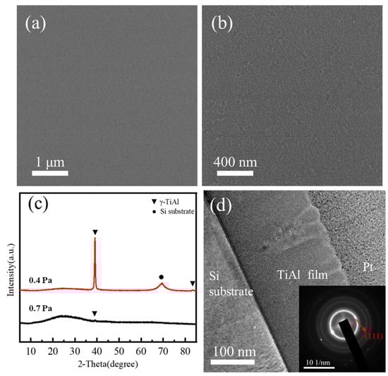
Figure 1.
(a,b) HIM surface images of TiAl film grown at 0.7 Pa; (c) XRD patterns of TiAl films produced at different Ar pressures (0.4 and 0.7 Pa); and (d) bright-field cross-sectional TEM images of TiAl film prepared at 0.7 Pa. The inset image is the corresponding SAED.
3.2. Helium Ion Implantation
- Figure 2 shows the helium profiles and implantation damage curves of 20 keV He implanted TiAl estimated using SRIM-2008 with the “Quick” K-P option, respectively [28,29]. It can be seen from the SRIM result that the helium atoms and the implantation damage are mainly concentrated in the TiAl film.

Figure 2.
The depth profile of helium atoms and DPA in the TiAl film implanted by 20 keV helium ion simulated using SRIM.
Figure 2.
The depth profile of helium atoms and DPA in the TiAl film implanted by 20 keV helium ion simulated using SRIM.

- Helium ion implantation was conducted at room temperature on N–A TiAl film using a helium ion microscope. The entire implantation process lasted 1578 s and the final helium ion implantation fluence was 4 × 10¹⁷ ions cm−2. As shown in Figure 3a–d, the partial bulge phenomenon emerged on the TiAl film surface during implantation. As the implantation time increased, the partial bulge phenomenon became more evident; the location is marked with a white dotted line as an example. At 300 s, a slight surface bulge could be seen, indicating that partial swelling had occurred in the N–A TiAl film. At 675 s, the bulge area became more pronounced and could be easily observed. Notably, the emergence of each bulge area occurred nearly simultaneously throughout the entire implantation region, and the evolution of the structure was nearly identical as implantation time progressed. This indicates that the origin of these partial bulge areas was uniform and not a chance occurrence. The boundaries between the bulge and the remaining area became more visible at 1245 and 1578 s. Moreover, the partial bulge areas were interconnected with each other. The partial bulge phenomenon may have originated in the partial amorphous regions in the N–A TiAl film, which swelled upon helium implantation. When the implantation was finished, there were no blisters or cracks on the N–A TiAl film surface, suggesting better implantation tolerance than nanocrystalline TiAl films [11].

Figure 3.
Morphological evolution of N–A TiAl film during helium ions implantation with a maximum dose of 4 × 10¹⁷ ions cm−2 of 20 keV helium ions: (a) 300 s; (b) 675 s; (c) 1245 s; and (d) 1578 s. Note that 300 s corresponds to a helium ions fluence of 0.76 × 10¹⁷ ions cm−2, 675 s to 1.71 × 10¹⁷ ions cm−2, 1245 s to 3.15 × 10¹⁷ ions cm−2, and 400 s to 4 × 10¹⁷ ions cm−2.

- To further investigate the structure evolution of the TiAl film, gradient helium ion implantation fluence experiments were performed on the adjacent areas of the same sample, and AFM was employed to characterize the surface structure of the implantation region. As illustrated in Figure 4a,d, a uniform arch-like surface structure could be seen, which was due to the enhancement of the sputtering and deposition rate at 0.7 Pa Ar pressure, resulting in low energy sputtering atoms; this is consistent with the results in Figure 1b. It decreased the critical nucleus size and nucleation force, giving rise to a fine fibrous morphology of approximately 20 nm in the structure. The Rq (the root mean square roughness, root mean square average of profile height deviations from the mean line) of the initial film was 2.12 nm, as shown in Table 1. In addition, the height map in Figure 4d* shows that the range of the sample surface height undulation was approximately 2 nm, indicating that the surface of the film was uniform and smooth. The surface structure of the TiAl film following 1 × 10¹⁷ ions cm−2 helium implantation fluence is shown in Figure 4b,e; slight bulges can be observed in partial areas, which has been rarely reported in previous studies. The appearance of these bulge areas led to an uneven film surface structure and an increase in the Rq value, up to 3.43 nm. From the height graph in Figure 4e* it can be seen that the height difference in bulging areas was approximately 10 nm. Furthermore, the arch-like surface structure of the N–A TiAl film was still evident in both the bulge areas and the surrounding areas, indicating that the alteration in the surface structure of the N–A TiAl film was not a result of exfoliation of the sample surface or thinning during the implantation process. It originated from the internal structural evolution of the film. Figure 4c,f show that the bulges on partial areas became more significant when the implantation fluence increased to 4 × 10¹⁷ ions cm−2. As can be seen from Figure 4f*, the bulge height reached approximately 50 nm. Table 1 shows the Rq of the implantation area with different helium ion fluences; the Rq increased rapidly with an increase in the implantation fluence, which was directly related to the continuous growth of the partial bulge structure.

Figure 4.
(a) 5 μm scan range; (d) 2 μm scan range, AFM images of the sample of the initial N–A TiAl film; (b) 5 μm scan range; (e) 2 μm scan range, AFM images of the sample of the N–A TiAl film with 1 × 10¹⁷ ions cm−2 20 keV He implantation; (c) 5 μm scan range; (f) 2 μm scan range, AFM images of the sample of the N–A TiAl film with 4 × 10¹⁷ ions cm−2 20 keV He implantation. (d*–f*) are the height graphs corresponding to the red lines in (d–f), respectively.


Table 1.
Surface roughness of N–A TiAl film with various 20 keV helium implantation fluences. Rq is the root mean square roughness.
Table 1.
Surface roughness of N–A TiAl film with various 20 keV helium implantation fluences. Rq is the root mean square roughness.
| Implantation Fluence (×1017 Ions cm−2) | 0 | 1 | 2 | 3 | 4 |
|---|---|---|---|---|---|
| Rq (nm) | 2.12 | 3.43 | 8.30 | 13.9 | 18.5 |
- To explore the N–A TiAl film evolution process, the cross-sectional of the post-implanted film with a helium ion implantation fluence of 2 × 10¹⁷ ions cm−2 was observed with TEM. As shown in Figure 5a, swelling appeared on the partial area with a width of approximately 100 nm (the example is marked by arrows) compared to the initial N–A TiAl film image in Figure 1d, which was consistent with the HIM and AFM results. A typical amorphous structure was found beneath each of the swelling areas and the swelling height of the amorphous region was approximately 30 nm compared to the surrounding area. As shown in Figure 5b, the helium bubbles were distributed in bands at depths from 100 to 220 nm (the region marked with white dotted lines). Many small and irregular bubbles showed a light contrast, suggesting a low mass/atomic number density. The size of He-induced spherical bubbles was 2–3 nm, which was related to the production of He clusters. The bubbles decreased in diameter from the middle of the band to both sides, indicating that the bubble size was associated with the helium atoms’ concentration. This can be attributed to the isotropic and a large free volume of amorphous structure. Additionally, the presence of grains below each sunk region should be noted. When the grains were exposed to helium implantation, there were slight swelling phenomena (approximately 20 nm) in the grain region compared with the initial N–A TiAl film thickness. As shown in Figure 5c, the interplanar spacing of the grains increased to 0.233 nm, which was larger than the initial N–A TiAl film (0.231 nm, calculated via XRD and SAED). The expansion of interplanar spacing can be attributed to the formation of helium atoms or bubble structures in grains, resulting in a swelling of grains. It exhibited lighter swelling than the amorphous region because of the lattice structure within the grain.

Figure 5.
TEM images of the N–A TiAl film with a helium implantation fluence of 2 × 10¹⁷ ions cm−2. (a) Low magnification bright field image; (b) high magnification bright field image; and (c) HRTEM image.
Figure 5.
TEM images of the N–A TiAl film with a helium implantation fluence of 2 × 10¹⁷ ions cm−2. (a) Low magnification bright field image; (b) high magnification bright field image; and (c) HRTEM image.

- The above results indicate that the uneven surface structure observed in N–A TiAl films during helium ion implantation was due to the difference in swelling rates between the amorphous and grain regions. The low diffusion of helium atoms and the presence of excessive free volume in the amorphous regions resulted in a higher swelling rate compared to the grain regions at the same implantation fluence. With increasing implantation fluence, the concentration of helium atoms increased, leading to an increase in the volume occupied by helium bubbles and a persistent bulge in the amorphous regions. The rounded shape of the surface bulge, instead of a uniform swelling, could be attributed to the presence of grains around the amorphous regions during the swelling process, which led to an uneven distribution of helium atoms’ concentration in the same depth and resulted in a more pronounced rounded surface structure. On the other hand, the low swelling rate in grain regions could be attributed to the presence of lattice structures and the diffusion of helium atoms along (111) planes to the interface [30,31]. Additionally, the helium atoms inside the grain tended to diffuse to the interface because of the strong helium sinking effect of the amorphous–nanocrystalline interface. It reduced the concentration of helium atoms making it more difficult to reach the critical dose for blister and inhibited the emergence of larger plate structures inside the grain, delaying surface blistering and improving the irradiation resistance of the N–A TiAl film.
4. Conclusions
In summary, nanocrystalline–amorphous biphase TiAl film was prepared via magnetron sputtering at 0.7 Pa Ar pressure, and its surface structure evolution was observed in situ during helium ion implantation, taking advantage of the HIM. Partial region swelling was detected; the TEM result revealed that this partial swelling phenomenon was derived from the amorphous structure of the nanocrystalline–amorphous biphase TiAl film. The isotropic and inherent excessive free volume of amorphous structure led to swelling in the amorphous region that became more pronounced with increasing implantation fluence. The amorphous region could effectively prevent the expansion of plate structure inside the film and delay the appearance of blistering. The helium resistance of materials may be effectively improved via the biphase structure of matrix materials, which provides a viewpoint for designing new radiation-tolerant materials for an advanced nuclear reactor.
Author Contributions
P.L.: methodology, software, and writing—original draft. L.T.: validation, investigation, and writing—review and editing. J.C. and X.L.: data curation. Y.M.: investigation and data curation. X.M.: conceptualization, writing—review and editing, and funding acquisition. All authors have read and agreed to the published version of the manuscript.
Funding
This work has been supported by the Scientific Instrument Developing Project of the Chinese Academy of Sciences, Grant No. YJKYYQ20170014.
Institutional Review Board Statement
Not applicable.
Informed Consent Statement
Not applicable.
Data Availability Statement
Not applicable.
Conflicts of Interest
The authors declare no conflict of interest.
References
- Brook, B.W.; Alonso, A.; Meneley, D.A.; Misak, J.; Blees, T.; van Erp, J.B. Why nuclear energy is sustainable and has to be part of the energy mix. Sustain. Mater. Technol. 2014, 1–2, 8–16. [Google Scholar] [CrossRef]
- Zhou, S.; Zhang, X. Nuclear energy development in China: A study of opportunities and challenges. Energy 2010, 35, 4282–4288. [Google Scholar] [CrossRef]
- Mansur, L.K.; Rowcliffe, A.F.; Nanstad, R.K.; Zinkle, S.J.; Corwin, W.R.; Stoller, R.E. Materials needs for fusion, Generation IV fission reactors and spallation neutron sources—Similarities and differences. J. Nucl. Mater. 2004, 329–333, 166–172. [Google Scholar] [CrossRef]
- Grimes, R.W.; Konings, R.J.M.; Edwards, L. Greater tolerance for nuclear materials. Nat. Mater. 2008, 7, 683–685. [Google Scholar] [CrossRef] [PubMed]
- WAS, G.S. Fundamentals of Radiation Materials Science: Metals and Alloys; Springer: New York, NY, USA, 2016. [Google Scholar]
- Oliviero, E.; Beaufort, M.F.; Barbot, J.F. Dislocations induced by bubble formation in high energy He implantation in silicon. J. Appl. Phys. 2001, 89, 5332–5338. [Google Scholar] [CrossRef]
- Yang, Q.; Fan, H.; Ni, W.; Liu, L.; Berthold, T.; Benstetter, G.; Liu, D.; Wang, Y. Observation of interstitial loops in He + irradiated W by conductive atomic force microscopy. Acta Mater. 2015, 92, 178–188. [Google Scholar] [CrossRef]
- Fan, C.; Li, C.; Parish, C.M.; Katoh, Y.; Hu, X. Helium effects on the surface and subsurface evolutions in single-crystalline tungsten. Acta Mater. 2021, 203, 116420. [Google Scholar] [CrossRef]
- Yang, Q.; You, Y.-W.; Liu, L.; Fan, H.; Ni, W.; Liu, D.; Liu, C.S.; Benstetter, G.; Wang, Y. Nanostructured fuzz growth on tungsten under low-energy and high-flux He irradiation. Sci. Rep. 2015, 5, 10959. [Google Scholar] [CrossRef]
- Wang, W.; Roth, J.; Lindig, S.; Wu, C.H. Blister formation of tungsten due to ion bombardment. J. Nucl. Mater. 2001, 299, 124–131. [Google Scholar] [CrossRef]
- Liu, P.; Tian, L.; Li, X.; Ma, Y.; Xia, J.; Meng, X. Structural evolution of amorphous and nanocrystalline TiAl films under helium implantation. Surf. Coat. Technol. 2022, 441, 128523. [Google Scholar] [CrossRef]
- Tian, L.; Liu, P.; Li, X.; Ma, Y.; Meng, X. Cracks and blisters formed in nanocrystalline tungsten films by helium implantation. Fusion Eng. Des. 2021, 172, 112879. [Google Scholar] [CrossRef]
- Zinkle, S.J.; Busby, J.T. Structural materials for fission & fusion energy. Mater. Today 2009, 12, 12–19. [Google Scholar] [CrossRef]
- Zinkle, S.J.; Snead, L.L. Designing Radiation Resistance in Materials for Fusion Energy. Annu. Rev. Mater. Res. 2014, 44, 241–267. [Google Scholar] [CrossRef]
- Chen, H.; Hai, Y.; Zhan, X.; Liu, X.; Xu, J.; Yin, W. Nano-amorphous layers improve the helium swelling resistance of a CAC-type nanocomposite. J. Appl. Phys. 2021, 129, 185301. [Google Scholar] [CrossRef]
- Su, Q.; Price, L.; Colon Santana, J.A.; Shao, L.; Nastasi, M. Irradiation tolerance of amorphous SiOC/crystalline Fe composite. Mater. Lett. 2015, 155, 138–141. [Google Scholar] [CrossRef]
- Ludy, J.E.; Rupert, T.J. Amorphous intergranular films act as ultra-efficient point defect sinks during collision cascades. Scr. Mater. 2016, 110, 37–40. [Google Scholar] [CrossRef]
- Schuler, J.D.; Grigorian, C.M.; Barr, C.M.; Boyce, B.L.; Hattar, K.; Rupert, T.J. Amorphous intergranular films mitigate radiation damage in nanocrystalline Cu-Zr. Acta Mater. 2020, 186, 341–354. [Google Scholar] [CrossRef]
- Neelav, A.H.; Pal, S.; Deng, C. Atomistic investigation of the deformation mechanisms in nanocrystalline Cu with amorphous intergranular films. J. Appl. Phys. 2019, 126, 125101. [Google Scholar] [CrossRef]
- Xia, Q.; Ren, P.; Meng, H. High performance of amorphous nanocrystalline composite structure materials. J. Mater. Res. Technol. 2022, 18, 4479–4485. [Google Scholar] [CrossRef]
- Khalajhedayati, A.; Pan, Z.; Rupert, T.J. Manipulating the interfacial structure of nanomaterials to achieve a unique combination of strength and ductility. Nat. Commun. 2016, 7, 10802. [Google Scholar] [CrossRef]
- Zhang, Y.; Chen, J.; Sun, G.; Huang, H.; Tong, L.; Wang, M.; Li, H.; He, X.; He, X.; Zhang, K.; et al. Strain rate-dependent hardness and deformation behavior in the nanocrystalline/amorphous Ti2AlNb film. Surf. Coat. Technol. 2021, 412, 127040. [Google Scholar] [CrossRef]
- Hishinuma, A.; Fukai, K.; Sawai, T.; Nakata, K. Ductilization of TiAl intermetallic alloys by neutron-irradiation. Intermetallics 1996, 4, 179–184. [Google Scholar] [CrossRef]
- Kondo, T.; Watanabe, Y.; Yi, Y.S.; Hishinuma, A. An evaluation of potential material–coolant compatibility for applications in advanced fusion reactors. J. Nucl. Mater. 1998, 258–263, 2083–2087. [Google Scholar] [CrossRef]
- Seki, Y.; Tabara, T.; Aoki, I.; Ueda, S.; Nishio, S.; Kurihara, R. Impact of low activation materials on fusion reactor design. J. Nucl. Mater. 1998, 258–263, 1791–1797. [Google Scholar] [CrossRef]
- Shepherd, D. Technology readliness level (TRL) assessment of cladding alloys for advanced nuclear fuels. In Proceedings of the Structural Materials for Innovative Nuclear Systems (SMINS-3), Nuclear Energy Agency Organisation for Economic Co-Operation and Development, Idaho Falls, ID, USA, 3 April 2015; pp. 108–116. [Google Scholar] [CrossRef]
- Thornton, J.A. Influence of apparatus geometry and deposition conditions on the structure and topography of thick sputtered coatings. J. Vac. Sci. Technol. 1974, 11, 666–670. [Google Scholar] [CrossRef]
- Ziegler, J.F. SRIM-2003. Nucl. Instrum. Methods Phys. Res. Sect. B Beam Interact. Mater. At. 2004, 219–220, 1027–1036. [Google Scholar] [CrossRef]
- Ziegler, J.F.; Ziegler, M.D.; Biersack, J.P. SRIM—The stopping and range of ions in matter. Nucl. Instrum. Methods Phys. Res. Sect. B Beam Interact. Mater. At. 2010, 268, 1818–1823. [Google Scholar] [CrossRef]
- Cao, Y.; Li, H.; Szpunar, J.A.; Shmayda, W.T. Effects of textures on hydrogen diffusion in nickel. Mater. Sci. Forum. 2002, 408–412, 1139–1144. [Google Scholar] [CrossRef]
- Mohammadzadeh, R.; Mohammadzadeh, M. Texture dependence of hydrogen diffusion in nanocrystalline nickel by atomistic simulations. Int. J. Hydrogen Energy 2018, 43, 7117–7127. [Google Scholar] [CrossRef]

Disclaimer/Publisher’s Note: The statements, opinions and data contained in all publications are solely those of the individual author(s) and contributor(s) and not of MDPI and/or the editor(s). MDPI and/or the editor(s) disclaim responsibility for any injury to people or property resulting from any ideas, methods, instructions or products referred to in the content. |
© 2023 by the authors. Licensee MDPI, Basel, Switzerland. This article is an open access article distributed under the terms and conditions of the Creative Commons Attribution (CC BY) license (https://creativecommons.org/licenses/by/4.0/).