Abstract
An iron aluminide modified layer prepared by a novel powder mixed electrical discharge alloying (PMEDA) process with a green compact aluminum electrode is conducted to improve the corrosion performance of work pieces. The phase composition and microstructure of the modified samples are analyzed by Scanning Electron Microscope (SEM), Energy Dispersive Spectroscopy (EDS), X-ray Diffraction (XRD) and Transmission Electron Microscope (TEM). Corrosion performance is investigated by the electrochemical workstation and the mechanism of corrosion resistance improvement is explored. The 12A modified samples exhibit a hydrophobic 102.4° contact angle, while showing 669% and 40% less corrosion current density in the simulated aqueous corrosion condition in comparison with the non-treated and non-hydrophobic modified samples, respectively. These enhanced performances are attributed to the synchronization of a hydrophobic surface, corrosion-proof iron aluminide and a dense, well-distributed modified layer.
1. Introduction
As the environment continuously deteriorates today, corrosion causes huge loss and severe safety risk in modern industries. Especially for marine nuclear power generation, the safety problem attracts global concern. In the marine condition, the severity of corrosion largely depends on the penetration depth of corrosive ions. Building protective coatings is the most common way to protect marine construction and restrict the penetration of corrosive ions [1,2,3,4].
With features of low density, high strength and excellent corrosion resistance, iron aluminides, which consist of FeAl, Fe3Al, Fe5Al2 and Al13Fe4 (could be referred to Al3Fe), are regarded as a kind of practical structural and fascinating candidate material for barrier materials applied in marine nuclear power generation systems and petrochemical industries [1,5,6,7]. Given the potential applications of iron aluminide, investigations to fabricate iron aluminide modified surface layers have been conducted, and several methods including Mechanical Alloying (MA), Electron Beam Physical Vapor Deposition (EB-PVD) and Laser Cladding (LC) have been developed for the fabrication of iron aluminide in recent years. Nevertheless, there are some challenges with applying iron aluminide in surface modification against aqueous corrosion [8,9,10]. Firstly, methods such as MA are insufficient for fabricating iron aluminide modified surface coatings [11,12]. Secondly, coatings fabricated by methods such as EB-PVD depict weak binding forces [13,14]. Thirdly, thermal defects of the machined surface are difficult to avoid during the process. Weak coating adhesive force and thermal defects would severely increase the risk of corrosive ion penetration to the substrate, leading to the occurrence of aqueous corrosion and failure.
Recent studies show that hydrophobic surfaces could effectively restrict the penetration of corrosive ion in an aqueous environment [15,16,17,18]. However, the conventional ways to fabricate protective coatings with hydrophobic surfaces require at least two or more steps, including fabrication of coatings and subsequent surface processing. Surplus steps lead to decreased efficiency. Hence, developing a practical, high-efficiency and controllable way to fabricate hydrophobic surfaces as well as anti-corrosion coatings to prolong the service life of barrier materials has attracted extensive research.
Electrical Discharge Machining (EDM) is a practical and conventional technique in material processing that involve removal of material via short-duration electrical discharge and high current density between the tool electrode and the work piece. By altering the polarity of work pieces and materials of the electrode, conventional machining processes could be changed to fabricate coatings on working pieces, making electrical discharge alloying (EDA) a practical surface modification method on the basis of conventional EDM [19,20,21,22]. Algodi et al. successfully fabricated a TiC/Fe coating on the surface of carbon steel and 304SS working piece by using semi-sintered electrode of titanium carbide [23]. Interestingly, several studies reveal that the surface morphology and roughness produced by EDM is strongly related to the discharge parameter, especially peak current. Crater, the basic topography of an EDM machined surface, is found to be related to the peak current of processing, while the dimension of crater would enlarge along with the increase in peak current [24,25]. Similar to laser cladding, thermal defects will limit the further application of EDA-modified layers in surface modification. Kumar et al. came up with a new machining process called Additive Electrical Discharge Machining (AEDM) by adding additive powder such as aluminum and titanium in fluid dielectrics to avoid the generation of thermal defects during EDM processing and accomplish a mirror-like machined surface [26]. Combined with the advantages of AEDM and EDA, it is reasonable to speculate that fabricating defect-free coatings with specialized surface roughness and morphology is feasible and controllable. Moreover, we have conducted a lot of work previously on applying EDM processing to surface modification and obtained some positive results. Therefore, we have accumulated some experience in the field of electrical discharge machining to guarantee the feasibility of this study [27,28].
In this study, we tried to propose a practical, simple and cost-effective approach with high efficiency for conducting an iron aluminide modified surface layer on the work piece. By the combined use of Powder Mixed Electrical Discharge Alloying (PMEDA) and the green compact electrode method to perform surface modification on the substrate, we expect to use one step to fabricate a novel, well-distributed iron-aluminide-containing surface-modified layer and a hydrophobic surface to restrict the penetration of corrosive ion in aqueous environments. It is expected that the hydrophobic surface would be fabricated via regulation of surface morphology under specific discharging parameters alongside the fabrication of an iron-aluminide-containing surface-modified layer. We expect that this work could be a simple and practical way to prolong service life in marine industries.
2. Experimental Procedures
2.1. Raw Materials
The selected substrate was 45# steel (Chinese standard GB699−88 equal to AISI 1045, with dimensions of 10 mm × 10 mm × 5 mm). Then, the substrates were polished to mirror-like surface and then ultrasonically cleaned in acetone and ethanol. The refined aluminum powder (3–5 μm particle size) produced by ALADDING was selected. Table 1 shows the chemical composition of 45# carbon steel.

Table 1.
Chemical composition of AISI1045 # carbon steel workpiece.
2.2. Preparation of Modified Layer
The green compact aluminum tool electrodes were obtained by the following steps: 100 wt.% aluminum powders (3 to 5 μm in size) were pressed into a die mold (ϕ 23 mm) and formed under a pressure of 130 MPa at room temperature. The working dielectric was a mixture of commercial EDM oil (major component: C11–C15 hydrocarbons) and aluminum powder (99.5% in purity, 1 to 3 μm in size) with an optimizing concentration of 5 g/L. The EDA process was carried out by a conventional EDM machine (JXD7125, Jiangsu DMT, and China). During the coating process, the green compact aluminum tool electrode and AISI1045 carbon steel work pieces were connected to the anode and cathode, respectively, and the working dielectric was used to fill the space between the electrode and the work piece. A stirrer was used to keep the aluminum powder suspended uniformly in the dielectric. Additionally, Figure 1 is the schematic model of PMEDA processing. Based on the previous research, it is reported that peak current is the most critical parameter, which could significantly affect the microstructure and morphology of the surface. The detailed experimental conditions are summarized in Table 2.
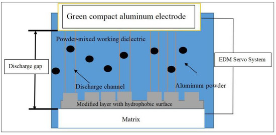
Figure 1.
Schematic model of one-step fabrication of iron aluminide containing hydrophobic modified layers.
Table 2.
EDA experimental conditions.
2.3. Selection of Optimized Parameter
Since the aim of this work is to fabricate a novel and well-distributed iron-aluminide-containing modified layer with a hydrophobic surface, this part will compare the quality of the modified layer and surface morphology fabricated under different processing parameters to acquire the optimized ones. Because the pulse-on time shows no influence on the thickness of the modified layer, we will focus on the influence of peak current and working dielectric on the modified layer.
Figure 2a,b show the cross-sectional SEM image of the modified layer fabricated in the same processing parameter (3A) but with a different working dielectric. From Figure 2a, the specimen processed with the normal working dielectric depicts an uneven modified layer with some thermal pores and cracks. This phenomenon results in the microrough flatness of specimens. During the conventional EDM processing, thousands of discharge channels with high spark energy are generated in the discharge gap. The presence of microrough flatness results in non-uniform energy dispersion on the surface of matrix. However, it is known that the uniformly suspended aluminum powders in dielectric reduce the spark energy and disperse random discharges throughout the machined surface [29]. Meanwhile, with high dielectric constant and low density, aluminum powder could uniformly suspend in spark gap, leading to an easy discharge breakdown. That means we could fabricate a modified layer and a surface with certain roughness at the same time. Therefore, the specimen processed in aluminum powder mixed with working dielectric manifest a novel and well-distributed modified layer with no thermal defects in Figure 2b. Figure 2c,d show the cross-sectional SEM images of 6A and 12A condition (powder-mixed dielectric, same pulse-on time). Both the 6A and 12A machined modified layers are well distributed, compact and high-quality. Furthermore, the microhardness (Figure 3a) of 6A and 12A modified layer samples ranges from 635 HV to 679 HV, which is 3 times higher than the 220 HV of non-treated samples. According to Figure 3b, the thickness of the modified layer increases with higher peak current. This phenomenon comes from the high dielectric constant of aluminum and discharge breakdown caused by higher peak current. Green compact aluminum bulk is selected as tool electrode. During the processing of EDA, pulse discharge arcs are continuously generated between the tool electrode and the work piece immersed in a liquid dielectric. Meanwhile, the energy generated from the pulse discharge arcs melts the tool electrode materials and pyrolyzes the dielectric [30]. Then, subsequent reaction forms a modification layer. With a high dielectric constant, the aluminum electrode could be easily melted under high peak current. Under the synchronization of suspending aluminum powder in the spark gap, the modified layers in 6A and 12A are thick, compact and well distributed. Additionally, the results of microhardness further prove the successful fabrication of modified layers on the AISI 1045 substrates.

Figure 2.
Cross-sectional SEM image of modified layer fabricated in same processing parameter as (a) non powder-mixed working dielectric, (b) (3A), (c) 6A and (d) 12A condition (aluminum-powder-mixed dielectric, same pulse-on time).

Figure 3.
Micro hardness (a) and thickness (b) of modified layer with different peak current.
To assess the wettability of the modified layers, the contact angle of 3.5 wt.% sodium chloride drops deposited onto the surface of all samples was measured by an optical contact angle meter (SD-CAZ2, Shengding Precision Instrument Co., Ltd., Dongguan, China). Figure 4 shows the contact angle of a sodium chloride solution droplet on modified layers machined with different peak currents. According to the results, the contact angle increases alongside the increasing in peak current. However, there is no obvious increase in contact angle for the machined surface compared to the non-treated surface when the peak current is less than 9A (89.3° vs. 85°). Additionally, when the peak current is increased to 12A, the contact angle rises to a hydrophobic value of 102.4°. It is expected that many craters occur on the machined surface after the EDA process. According to Cassie’s law, it seems that the craters on the 12A machined surface facilitate the tracking of air and then form air packets which lead to the repellency of the aqueous medium, exhibiting a hydrophobic character. It is reported that materials with more hydrophobic character are typically more resistant against corrosion in aqueous environments. Thus, it is reasonable to believe that the 12A machined surface shows better anti-corrosion performance as shown in the following section. Additionally, characterization will be conducted on the 12A machined sample.

Figure 4.
Contact angle of a sodium chloride solution droplet on modified layers machined with different peak currents and the non-treated surface.
2.4. Characterization of Iron-Aluminide-Containing Modified Layers
Morphology observation and analysis of the composition of the modified layers were undertaken by means of SEM (S-3400N-II, Hitachi, Tokyo, Japan) equipped with energy dispersive spectroscopy (EDS) (Inca Energy 350, Oxford, UK). The phase composition and crystal structure of the modified layers were examined by X-ray Diffraction using Cu Kα radiation with a wavelength of 0.15418 nm (D/max-γA10, Rigaku, Tokyo,Japan). Its microstructure was further examined by TEM (Tecnai G2 F20 S-Twin, FEI, Columbia, MD, USA). The plane-view TEM foil was obtained firstly by mechanical polishing (from the side of substrate until its thickness was about 60 μm) and then ion polishing (691PIPS, Gatan, Pleasanton, CA, USA). The electrochemical study of the corrosion performance of those modified layers as well as the untreated sample was carried out by an electrochemical workstation (CHI660E, CH Instruments, Shanghai, China) in a standard three-electrode system. All measurements were conducted in a 3.5 wt.% NaCl solution at room temperature with a geometrical working area of 1 cm2. A Pt mesh and a saturated calomel electrode (SCE) were used as counter and reference electrodes, respectively. The linear polarization measurement was performed ranging from open circuit potential (OCP) ± 500 mV at the scanning rate of 0.5 mV s−1. Electrochemical impedance spectroscopy ranging from 105 Hz to 0.01 Hz was performed with excitation signals of 5 mV amplitude at OCP. Before the EIS and Tafel measurements, the work electrodes were immerged in the electrolyte for one hour to reach a stable state.
3. Results and Discussion
3.1. Morphology, Composition and Microstructure of Iron Aluminide Modified Layers
Figure 5 shows the surface morphology of the EDA machined surface with 12A peak current. It is characterized by overlapping craters, debris and chimneys, which are formed by entrapped gases escaping from the redeposited material. This phenomenon corresponds to the above wettability experimental results. Like Cassie’s law, the presence of this craters could store and trap air. Additionally, the air helps to lift the sodium chloride droplet. It is expected that the modified layer may possess good corrosion resistance in a sodium chloride aqueous environment. We will conduct electrochemical experiments in the following section for confirmation.
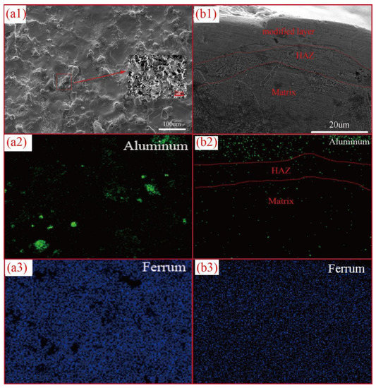
Figure 5.
SEM images and element mapping images of surface morphology (a1–a3) and cross-sectional morphology (b1–b3) of 12A PMEDA machined samples.
Both of the surface and cross-sectional EDS results indicate that the domain elements of the EDA machined surface are ferrum and aluminum (Figure 5(a1–a3,b1–b3). Obviously, the aluminum elements originate from the aluminum green compact electrode and the aluminum powders suspended in mixed dielectric. Furthermore, the uniform distribution of these elements reveals the uniform structure of the modified layer. Figure 5(b1) shows the cross-sectional SEM image of the 12A machined modified layer. Three distinctive regions, namely, Modified Layer, Heat Affected Zone (HAZ) and Matrix, are observed. Unlike the other two regions, the modified layer is not be etched by 4 wt.% initially, clearly showing that its thickness is about 20 μm. It is worth noticing that there is no obvious crack on the modified layer. This can be mainly attributed to the aluminum powder mixed dielectric.
Figure 6 shows the XRD of the modified layer. Several phases are identified, including Al13Fe4, Fe and Al, which agree with the EDS results. The successive pulsed discharged arcs between the tool electrode and work piece produce plasma channels with high thermal energy, which dissolve aluminum electrodes as well as aluminum powders around the plasma channel and melt the AISI 1045 steel surface, forming a micro ferrum melt pool on its surface. The dissolved aluminum elements are transferred and reacted with ferrum in the melt pool, forming Al13Fe4 precipitates in situ. The small amount of aluminum can be attributed to the incomplete combination of dissolved aluminum elements and melting ferrum before the extremely fast resolidification of the micro melt pool. In fact, this incomplete reaction phenomenon is common in EDA processes when pure metal green compact bulk is used as a tool electrode. Thus, the modified surface layers are in situ composites, and consist of Al13Fe4 precipitates and aluminum phases dispersing in the ferrum matrix. It is believed that the appearance of Al13Fe4 precipitate will benefit the improvement in corrosion resistance of the modified surface due to its intrinsic good corrosion resistance.

Figure 6.
XRD of the PMEDA machined surface with 12A peak current.
TEM observation is used to further analyze the microstructure of the modified layer. The bright-field TEM image of the top surface of the modified layer shows two regions with distinctive contrasts (Figure 7). The dark areas are identified by the selected area electron diffraction patterns as the Al13Fe4 phase independent of their shape and size, while the bright areas as the Fe phase.

Figure 7.
Bright-field TEM image of top surface of the EDA machined surface with 6A peak current, the inset is the selected area electron diffraction patterns of the red box area, demonstrating the existence of Al13Fe4 phase (lower right) and Fe phase (upper left).
3.2. Electrochemical Corrosion Behavior of PMEDA Machined Surfaces in Chloride Media
In order to simulate a marine aqueous environment, all the corrosion tests were conducted in 3.5% sodium chloride solution. The 6A and 12A machined samples were selected as the candidates to compare the aqueous corrosion resistance of hydrophobic and hydrophilic surfaces.
Figure 8 illustrates overall potentiodynamic behavior of the PMEDA machined surface with different peak currents and the non-treated counterpart. The relevant electrochemical parameters are calculated according to the intersection point of the two tangents, respectively, of the anodic and cathodic Tafel lines [31], and all the data are listed in Table 3. The anodic polarization branches of all the samples show similar characteristics, without showing any significant passive behavior, instead of showing the pitting corrosion after corrosion potential (Ecorr). Similar corrosion behavior was observed for the iron-aluminide-containing coatings on austenitic stainless steels [32]. However, the PMEDA machined surface shows higher corrosion potential and lower corrosion current density compared to the non-treated surface regardless of the peak current. This phenomenon should be associated with the presence of the high corrosion resistance of the Al13Fe4 phases. It is worth noticing that the 6A and 12A machined surfaces exhibit similar corrosion potential, in agreement with their analogous chemical composition. However, corrosion current density for the 12A machined surface is 40% lower than that of the 6A machined surface, indicating that other factors, for example the wettability, affect its corrosion behavior.

Figure 8.
Polarization diagrams of the EDA machined surface with different peak current and the non-treated counterpart.
Table 3.
Electrochemical linear polarization parameters of the EDA machined surface with different peak current along with the non-treated counterpart. βa: anodic tafel slope, βc: cathodic tafel slope.
The EIS is used to further understand the effect of Al13Fe4 phases and surface wettability on the anti-corrosion performance of the PMEDA-modified surface. The EIS diagrams and the fitted results of the 6A and 12A machined surfaces along with the reference non-treated surface in 3.5 wt.% NaCl aqueous solution at 25 °C are shown in Figure 9. The relevant electrochemical equivalent circuits are shown in Figure 10, and the values of the equivalent circuit elements are listed in Table 4. The physical meaning of the equivalent circuit elements was different for these three samples. In all the cases, R0 is associated with electrolyte resistance. In regard to the non-treated surface, the constant phase element (CPE), Q1, represents the redox capacitance and R1 accounts for the charge transfer resistance of the corrosion process on the substrate. Concerning the 6A machined surface, Q1 accounts for the dielectric contribution of the obtained modified layer, whereas R1 corresponds to this passive film resistance. The other CPE, Q2, represents the double-layer capacitance and R2 accounts for the charge transfer resistance of the corrosion process through the modified layer. Given the hydrophobic property of the 12A machined surface with respect to the 6A machined surface, an additional CPE, Q3, is added in its equivalent circuit to account for the dielectric contribution of the air trapped within the modified layer [31]. The comparison of the three samples shows a greater semicircle diameter in Nyquist diagrams for the PMEDA-modified surfaces, suggesting a higher corrosion resistance regarding the non-treated surface. Indeed, the fitting results reveal that the total resistance (Rtotal = R1 + R2) of the corrosion process for the 6A machined surface and 12A machined surface is 5159 ± 175 Ω and 9239 ± 275 Ω which, respectively is about 8 times and 14 times larger than that of the referenced non-treated surface. This behavior is in agreement with the results of polarization curve measurements and confirms that a crack-free modified layer yields a good barrier effect due to the compact structure of the modified layer and the presence of the uniform Al13Fe4 phases with an anti-corrosion property. It is worth mentioning that the 12A machined surface shows lower corrosion current density than the 6A machined surface mainly because of its significantly increased charge transfer resistance of the corrosion process through the modified layer. This is related to its special surface roughness. It benefits from tracking air and then forms air packets, inhibiting the penetration of chloride ions into the substrate and electron transfer from electrolyte to electrode surface by decreasing the useful conductive area.
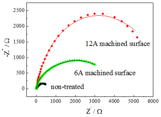
Figure 9.
Nyquist impedance diagrams and the fitted results of 6A and 12A machined surfaces along with the reference non-treated surface in 3.5 wt.% NaCl aqueous solution at 25 °C. The symbols are the experimental data whereas the continuous lines represent the fitted spectra.

Figure 10.
Electrochemical equivalent circuits for EIS of the samples: (a) the non-treated, (b) 6A PMEDA machined surface and (c) 12A PMEDA machined surface.
Table 4.
Values of the equivalent circuit elements to fit EIS for the EDA machined surface with different peak current along with the non-treated counterpart.
4. Conclusions
Hydrophobic modified layers of in situ Al13Fe4 precipitate containing an iron matrix have been successfully one-step prepared on the surface of AISI 1045 carbon steel by the PMEDA process. The combination of a green compact aluminum electrode and aluminum powder mixed dielectric leads to the obtained modified layers being free of cracks and having a uniform distribution of Al13Fe4 precipitates in the iron matrix as well as a hydrophobic surface. It is these advantages that result in the PMEDA machined surfaces (6A and 12A modified samples) showing a 35% and 27% higher corrosion potential, respectively, and a 360% and 669% lower corrosion current density, respectively, in a 3.5 wt.% NaCl solution compared to the non-treated surface. In particular, when the 12A PMEDA-modified surface exhibits a hydrophobic character, its corrosion current density further decreases. This can be attributed to the specific hydrophobic property of the PMEDA machined surface, tracking air and forming subsequent air packets to inhibit penetration of chloride ions into the substrate and electron transfer from electrolyte to electrode surface by decreasing the useful conductive area.
Author Contributions
Conceptualization, W.L. and X.J.; methodology, X.J.; software, W.L.; validation, W.L. and X.J.; formal analysis, W.L.; investigation, W.L.; resources, W.L.; data curation, W.L.; writing—original draft preparation, W.L.; writing—review and editing, X.J.; visualization, W.L.; supervision, X.J.; project administration, X.J.; funding acquisition, X.J. All authors have read and agreed to the published version of the manuscript.
Funding
Financial support by the National Natural Science Foundation of China (No. 51075075), the Projects of Talents Recruitment of Guangdong University of Petrochemical Technology and the Open Foundation of Guangdong Provincial key laboratory of Petrochemical Equipment Fault Diagnosis (No.91720212) are gratefully acknowledged.
Institutional Review Board Statement
Not applicable.
Informed Consent Statement
Not applicable.
Data Availability Statement
Not applicable.
Conflicts of Interest
The authors declare no conflict of interest.
References
- Rodriguez-Diaz, R.A.; Uruchurtu-chavarin, J.; Molina-Ocampo, A.; Porcayo-Calderon, J.; Mendoza, M.E.; Valdez, S.; Juarez-Islas, J. Hot Corrosion Behavior of FeAl Intermetallic Compound Modified with Silver in Molten Salt Mixture. Int. J. Electrochem. Sci. 2013, 8, 11877–11895. [Google Scholar]
- He, Y.; Li, G.; Hwang, K.; Boluk, Y.; Claesson, P.M. Nano-scale mechanical and wear properties of a corrosion protective coating reinforced by cellulose nanocrystals—Initiation of coating degradation. Appl. Surf. Sci. 2021, 537, 147789. [Google Scholar] [CrossRef]
- Gnedenkov, A.; Sinebryukhov, S.; Mashtalyar, D.; Vyaliy, I.; Egorkin, V.; Gnedenkov, S. Corrosion of the Welded Aluminium Alloy in 0.5 M NaCl Solution. Part 2: Coating Protection. Materials 2018, 11, 2177. [Google Scholar] [CrossRef] [PubMed]
- Cui, M.; Wang, P.; Wang, Z.; Wang, B. Mangrove Inspired Anti-Corrosion Coatings. Coatings 2019, 9, 725. [Google Scholar] [CrossRef]
- Sharma, G.; Singh, P.R.; Sharma, R.K.; Gaonkar, K.B.; Ramanujan, R.V. Aqueous corrosion behavior of iron aluminide Intermetallics. J. Mater. Eng. Perform. 2007, 16, 779–783. [Google Scholar] [CrossRef]
- Natesan, K. Corrosion performance of iron aluminides in mixed-oxidant environments. Mater. Sci. Eng. A-Struct. 1998, 258, 126–134. [Google Scholar] [CrossRef]
- Feng, Y.; Shan, J.; Zhao, L.; Liu, Z.; Gong, K.; Li, C. Effect of Cr3C2 Content on the Microstructure and Wear Resistance of Fe3Al/Cr3C2 Composites. Coatings 2022, 12, 1980. [Google Scholar] [CrossRef]
- Bax, B.; Schäfer, M.; Pauly, C.; Mücklich, F. Coating and prototyping of single-phase iron aluminide by laser cladding. Surf. Coatings Technol. 2013, 235, 773–777. [Google Scholar] [CrossRef]
- PalDey, S.; Deevi, S.C. Single layer and multilayer wear resistant coatings of (Ti,Al)N: A review. Mater. Sci. Eng. A 2003, 342, 58–79. [Google Scholar] [CrossRef]
- Pogrebnjak, A.; Smyrnova, K.; Bondar, O. Nanocomposite Multilayer Binary Nitride Coatings Based on Transition and Refractory Metals: Structure and Properties. Coatings 2019, 9, 155. [Google Scholar] [CrossRef]
- Krasnowski, M.; Kulik, T. Nanocrystalline and amorphous Al–Fe alloys containing 60–85% of Al synthesised by mechanical alloying and phase transformations induced by heating of milling products. Mater. Chem. Phys. 2009, 116, 631–637. [Google Scholar] [CrossRef]
- Wismogroho, A.S.; Widayatno, W.B.; Suryadi; Thosin, K.A.Z.; Rochman, N.T.; Sueyoshi, H. Iron aluminide coating on Al by mechanical alloying. Surf. Eng. 2011, 27, 126–133. [Google Scholar] [CrossRef]
- Sasaki, H.; Kita, K.; Nagahora, J.; Inoue, A. Nanostructures and Mechanical Properties of Bulk Al-Fe Alloys Prepared by Electron-Beam Deposition. Mater. Trans. 2001, 42, 1561–1565. [Google Scholar] [CrossRef]
- Movchan, B.A. Discrete nanosized metallic coatings produced by EB-PVD. Surf. Eng. 2016, 32, 258–266. [Google Scholar] [CrossRef]
- Wu, L.; Zhang, X.; Hu, J. Corrosion protection of mild steel by one-step electrodeposition of superhydrophobic silica film. Corros. Sci. 2014, 85, 482–487. [Google Scholar] [CrossRef]
- Zhang, Q.; Zhang, H. Corrosion resistance and mechanism of micro-nano structure super-hydrophobic surface prepared by laser etching combined with coating process. Anti-Corros. Methods Mater. 2019, 66, 264–273. [Google Scholar] [CrossRef]
- Lai, L.; Wu, H.; Mao, G.; Li, Z.; Zhang, L.; Liu, Q. Microstructure and Corrosion Resistance of Two-Dimensional TiO2/MoS2 Hydrophobic Coating on AZ31B Magnesium Alloy. Coatings 2022, 12, 1488. [Google Scholar] [CrossRef]
- Lu, F.; Cao, Z.-F.; Yang, F.; Wang, S.; Zhong, H. Fabrication of hydrophobic coating on electrolytic manganese surface for enhancing corrosion resistance. Prog. Org. Coatings 2019, 132, 379–387. [Google Scholar] [CrossRef]
- Murray, J.W.; Cook, R.B.; Senin, N.; Algodi, S.J.; Clare, A.T. Defect-free TiC/Si multi-layer electrical discharge coatings. Mater. Des. 2018, 155, 352–365. [Google Scholar] [CrossRef]
- Tyagi, R.; Darmalingam, K.; Patel, V.S.; Das, A.K.; Mandal, A. Deposition of WS2 and Cu nanopowder coating using EDC process and its analysis. Mater. Today Proc. 2019, 18, 5170–5176. [Google Scholar] [CrossRef]
- Tyagi, R.; Mandal, A.; Das, A.K.; Tripathi, A.; Prakash, C.; Campilho, R.; Saxena, K.K. Electrical Discharge Coating a Potential Surface Engineering Technique: A State of the Art. Processes 2022, 10, 1971. [Google Scholar] [CrossRef]
- Liew, P.J.; Yap, C.Y.; Wang, J.; Zhou, T.; Yan, J. Surface modification and functionalization by electrical discharge coating: A comprehensive review. Int. J. Extreme Manuf. 2020, 2, 12004. [Google Scholar] [CrossRef]
- Algodi, S.J.; Murray, J.W.; Brown, P.D.; Clare, A.T. Wear performance of TiC/Fe cermet electrical discharge coatings. Wear 2018, 402–403, 109–123. [Google Scholar] [CrossRef]
- Guo-liang, L.I.; Xiao-hua, J.; Bo, X.; Wen, L. Thermal Field Simulation of Electrical Discharge Coating in Liquid and Its Research. Surf. Technol. 2012, 41, 30–34. [Google Scholar]
- Takezawa, H.; Mohri, N.; Kusama, T. Changes in Surface Roughness Caused by Electrical Discharge Coating. Int. J. Autom. Technol. 2019, 13, 665–670. [Google Scholar] [CrossRef]
- Kumar, A.; Maheshwari, S.; Sharma, C.; Beri, N. Research Developments in Additives Mixed Electrical Discharge Machining (AEDM): A State of Art Review. Mater. Manuf. Process. 2010, 25, 1166–1180. [Google Scholar] [CrossRef]
- Xiao, H.; Jie, X.; Zeng, Z.; Li, G. Titanium carbonitride coating by pulsed electrical discharge in an aqueous solution of ethanolamine. Surf. Coat. Technol. 2014, 258, 1006–1010. [Google Scholar] [CrossRef]
- Xie, Z.J.; Mai, Y.J.; Lian, W.Q.; He, S.L.; Jie, X.H. Titanium carbide coating with enhanced tribological properties obtained by EDC using partially sintered titanium electrodes and graphite powder mixed dielectric. Surf. Coat. Technol. 2016, 300, 50–57. [Google Scholar] [CrossRef]
- Arun, I.; Duraiselvam, M.; Senthilkumar, V.; Narayanasamy, R.; Anandakrishnan, V. Synthesis of electric discharge alloyed nickel–tungsten coating on tool steel and its tribological studies. Mater. Des. 2014, 63, 257–262. [Google Scholar] [CrossRef]
- Kumar, S.; Singh, R.; Singh, T.P.; Sethi, B.L. Surface modification by electrical discharge machining: A review. J. Mater. Process. Technol. 2009, 209, 3675–3687. [Google Scholar] [CrossRef]
- Zhang, B.; Feng, H.; Lin, F.; Wang, Y.; Wang, L.; Dong, Y.; Li, W. Superhydrophobic surface fabricated on iron substrate by black chromium electrodeposition and its corrosion resistance property. Appl. Surf. Sci. 2016, 378, 388–396. [Google Scholar] [CrossRef]
- Mudali, U.K.; Bhuvaneswaran, N.; Shankar, P.; Raj, B. Corrosion behaviour of intermetallic aluminide coatings on nitrogen-containing austenitic stainless steels. Corros. Sci. 2004, 46, 2867–2892. [Google Scholar] [CrossRef]
Disclaimer/Publisher’s Note: The statements, opinions and data contained in all publications are solely those of the individual author(s) and contributor(s) and not of MDPI and/or the editor(s). MDPI and/or the editor(s) disclaim responsibility for any injury to people or property resulting from any ideas, methods, instructions or products referred to in the content. |
© 2023 by the authors. Licensee MDPI, Basel, Switzerland. This article is an open access article distributed under the terms and conditions of the Creative Commons Attribution (CC BY) license (https://creativecommons.org/licenses/by/4.0/).