Article

Monocrystalline Nickel Nanogrinding Subsurface Deformation-Layer Depth Study Based on Orthogonal Tests

1
Department of Mechanical Engineering, Taiyuan Institute of Technology, Taiyuan 030008, China
2
State Key Laboratory of Precision Measuring Technology & Instruments, Laboratory of MicroNano Manufacturing Technology, Tianjin University, Tianjin 300072, China
3
School of Mechanical and Transportation Engineering, Taiyuan University of Technology, Taiyuan 030006, China
*
Author to whom correspondence should be addressed.
Coatings 2023, 13(2), 410; https://doi.org/10.3390/coatings13020410
Submission received: 17 October 2022 / Revised: 7 February 2023 / Accepted: 9 February 2023 / Published: 11 February 2023

Abstract

:
Nanogrinding is one of the main technologies for machining complex surface shapes with nanometer-level precision. The subsurface deformation depth, as an important index of machining quality, directly affects the service life and mechanical properties of machined parts. In order to explore the factors that influence subsurface deformation depth, this work investigated the effects of three factors, namely, grinding speed, grinding depth and crystal orientation, along different crystal planes at the depth of the subsurface deformation layer in a monocrystalline nickel nanofabrication process. By combining molecular dynamics simulation and orthogonal tests, the results showed that, among the three aforementioned factors, the influence of crystal orientation at the depth of the subsurface deformation layer was the greatest, followed by that of grinding depth, while the influence of grinding speed was the weakest. Through the orthogonal tests, the factors affecting the significance of subsurface deformation depth were analyzed, and the results were found to be more meaningful compared with those of current single-factor studies. Meanwhile, in-depth exploration of the nanogrinding mechanism can provide the necessary theoretical basis for the development of nanomachining technology, which is of great significance for the improvement of ultra-precision cutting technology.

1. Introduction

Monocrystalline nickel-based alloys, which are difficult to machine, are primarily used in aerospace engines [1,2]. The shapes of the parts are complex, the structural-integrity requirements are high, the weight difference between the blank and the finished product is large, and most of the material is removed as a machining allowance. However, such materials face various problems, such as anisotropy, work hardening, severe tool wear and low production efficiency, in nanoprocessing, which seriously restricts the development of high-efficiency, low-damage micro-/nanosurface-part manufacturing technology.
Nanofabrication technology is the basis for processing micro-/nanomaterials and making microstructures and devices [3,4,5], and it has been highly developed in the manufacture of semiconductor chips, medical equipment, flexible materials and micro-/nanorobots. Regarding processing technology, from traditional macro- and microprocessing to nanoprocessing, machining accuracy has been constantly improving, and machining thicknesses are decreasing [6]. Nanofabrication is not simply a miniaturization of traditional macrofabrication. When the processing depth is in the nanometer range, the processing is essentially a discrete process, while traditi onal macrofabrication is based on continuum mechanics. The processing theory is not suitable for explaining the nanofabrication mechanism [7]. Many physical mechanisms in the nanofabrication process, such as the law of friction and the transition process of the brittle–ductility mechanism, are very different from those that are operative in traditional macrofabrication, and, due to the reduction in processing magnitude, size effects and microwear are more significant in nanofabrication.
Limited by experimental equipment and conditions, existing methods of nanofabrication are often difficult to control. Various impurities and factors in the experimental process also interfere with experimental phenomena and affect research on nanofabrication mechanisms. Therefore, modeling and simulation techniques are easier, faster and less expensive to realize in the theoretical study of nanofabrication. The nanofabrication method based on molecular dynamics (MD) simulation aims to explain the phenomena and principles in the nanofabrication process through transient changes in molecular atoms and serves to link macroscopic properties and microstructures [8]. Molecular dynamics simulation was originally used in chemistry, biology, materials science and other disciplines, and now it has become an important means of studying mechanisms in nanoscale machining.
The introduction of molecular dynamics simulation into the field of nanofabrication was first carried out by the Lawrence Laboratory of the United States in the late 20th century, when diamond tools were used to nanofabricate monocrystalline copper. Subsequently, domestic and foreign teams began to use molecular dynamics to study mechanical processing. Eder et al. [9,10,11] investigated the material removal rate of nanocrystalline carbon steel during nanogrinding by modeling three different scales, and a mesh-free multiscale modeling approach was proposed. Meanwhile, the authors of various other papers discussed in depth the microstructural evolution of subsurfaces by simulating the sliding of cuni alloys, elucidating the promotion of plastic deformation and surface damage. Wu et al. [12] developed a molecular dynamics model for 6H-SiC nanogrinding with two abrasive grains, and the influence of different grinding depths and abrasive grain spacing on grinding performance was analyzed. It was found that subsurface damage often appeared in the form of amorphous phase transitions and discrete dislocations, and that these damages would have significant effects on subsequent deformation and surface quality. The research of Karkalos and Markopoulos [13,14] mainly focused on the nanogrinding processing of monocrystalline materials. They investigated the formation of wear debris, grinding force, grinding temperature and workpiece deformation at different grinding depths and various grinding speeds; the relationship between processing preheating and material removal rate was also investigated. The team of Professor Fang of Tianjin University [15,16] investigated the mechanism of monocrystalline silicon-chip formation and single-layer graphite at the atomic scale and concluded that in the cutting of graphene, chips are produced by bending and sliding along the front face. With blunted edges, folding deformation dominates. On both the chip and the surface being machined, the atoms maintain the toroidal shape of the carbon layer and there are no defects in lattice topology. Dai [17] et al. investigated the ultra-high-speed nanofabrication of diamond and monocrystalline copper v-grooves using a molecular dynamics approach. The unequal heights of the sides of the v-grooves was found to be related to the tool rake angle. Zhang [18] et al. carried out molecular dynamics simulation of nanocutting on 6H-SiC with tool tilting, and the deformation mechanism of the 6H-SiC and the amorphization process were investigated. Zhao et al. [19] studied surface generation and residual stress in the process of monocrystalline silicon nanogrinding by adjusting machining parameters, such as grinding speed, ambient temperature, grinding depth, etc., and the suppression of subsurface damage layers was achieved by adjusting the machining parameters.
However, the above studies mostly focused on the effect of a single variable on nanofabrication and did not consider parameter changes in multiple variables. Therefore, the influence of the three variables of grinding speed, grinding depth and machining along different crystal planes at the depth of the subsurface deformation layer during nanogrinding of monocrystalline nickel was studied through orthogonal experiments in order to determine the effects of different machining parameters. The significant factors were examined in relation to optimal parameter combinations. The results provide the necessary theoretical basis for the development of high-quality aerospace equipment and high-efficiency nanocutting technology. It is also anticipated that they will provide theoretical guidance and technical support for the machining of other difficult-to-process materials.

2. Model and Simulation Conditions

In this manuscript, the program LAMMPS [20], a large-scale atomic and molecular parallel simulator, was used to perform molecular dynamics simulations, and the open-source tool OVITO [21] was used to identify programs to visualize atomic data. The software used for the analysis of orthogonal test data was the Orthogonal Design Assistant V3.1.
Figure 1 depicts the molecular dynamics model of grinding monocrystalline nickel. The diamond abrasive grains of the tool were spherical particles with radii of 2 nm. As the lattice constant of the monocrystalline nickel was a = 0.352 88 nm and periodic boundary conditions were used, the workpiece size was set to 60a × 60a × 30a, such that the dimensions of the cuboid monocrystalline nickel block were approximately 21.2 nm × 21.2 nm × 10.6 nm. The Y direction was set as the periodic boundary condition. Since monocrystalline nickel has a face-centered cubic (FCC) lattice, it has three crystal face groups. Regarding grinding in different crystal planes and different directions according to the common crystal orientations, where the following conditions obtain: (001) plane [100] direction, (110) plane [001] direction and (111) plane [ 1 ¯ 10] direction, the phrase “(001) plane [100] direction” means that the (001) plane is exposed in the grinding direction and that the tool is working on the (001) plane, along the [100] direction, the same holding, mutatis mutandis, for the other planes and directions. The three factors in the orthogonal test were set as grinding speed, grinding depth and grinding along different crystal planes.
The monocrystalline nickel atoms in Figure 1 are separated into a boundary layer, a thermostat layer and a Newtonian layer, from the outside to the inside. During the grinding simulation, the atoms in the boundary layer were held stationary, while the temperature of the atoms in the thermostat layer was maintained at 293 K. As temperature is strongly related to particle velocity, the thermostat layer’s temperature can be kept close to constant by redefining the particles’ velocity and kinetic energy [22]. At the same time, due to the distance between the atoms of the thermostatic layer and the machined surface, simulation times are short [23], and in classical molecular dynamics simulation, the thermal conductivity and the contribution of electrons are ignored, so that, for the simulated temperature, theoretically, there will be some errors with respect to the actual processing temperature [24]. The Newtonian layer of atoms participates in the processing, and the atoms are governed by Newton’s laws of mechanics. Table 1 presents the MD simulation parameters for monocrystalline nickel nanogrinding.
The potential functions in Table 1 represent atomic or intermolecular interaction forces, which are important parameters in molecular dynamics simulations. Ni atoms belong to metal atoms, and metal atoms frequently use the embedded atom method (EAM) function. The Morse potential function was used between the workpiece’s Ni atoms and the tool’s C atoms. The tool was configured as a rigid body, and its interatomic interaction forces were not considered in this study.
In order to investigate the influence of grinding depth, grinding speed and processing along different crystal surfaces at the depth of the subsurface deformation layer of monocrystalline nickel, an L9(34) orthogonal test was designed, as shown in Table 2. Nine representative points from the full-scale test were selected for analysis, as shown in Figure 2, to establish an efficient test method. The reason for setting the grinding speed was that it was found in a previous study that high-speed grinding can reduce single-crystal nickel subsurface defects with a single factor [27] and high-speed grinding can reduce molecular dynamics simulation time and improve efficiency.
Since the lattice deformation of subsurface atoms is difficult to observe, based on studies in the literature [28,29], the atomic potential energy change can be used to characterize the degree of atomic deformation, and then the depth of the deformed layer of the subsurface can be further calculated. Therefore, to study the depth of the subsurface deformation layer, 30 atoms directly below the workpiece passed by the abrasive tool were taken as 1 group in each model, for a total of 5 groups, and an atomic-potential energy-change curve was drawn to analyze the deformation. Five subsurface deformation-layer depth values were obtained, and the average value was taken. The values of the subsurface deformation-layer depths when grinding at various grinding speeds, grinding depths and along various crystal planes and orientations were thus obtained.

3. Results and Analysis

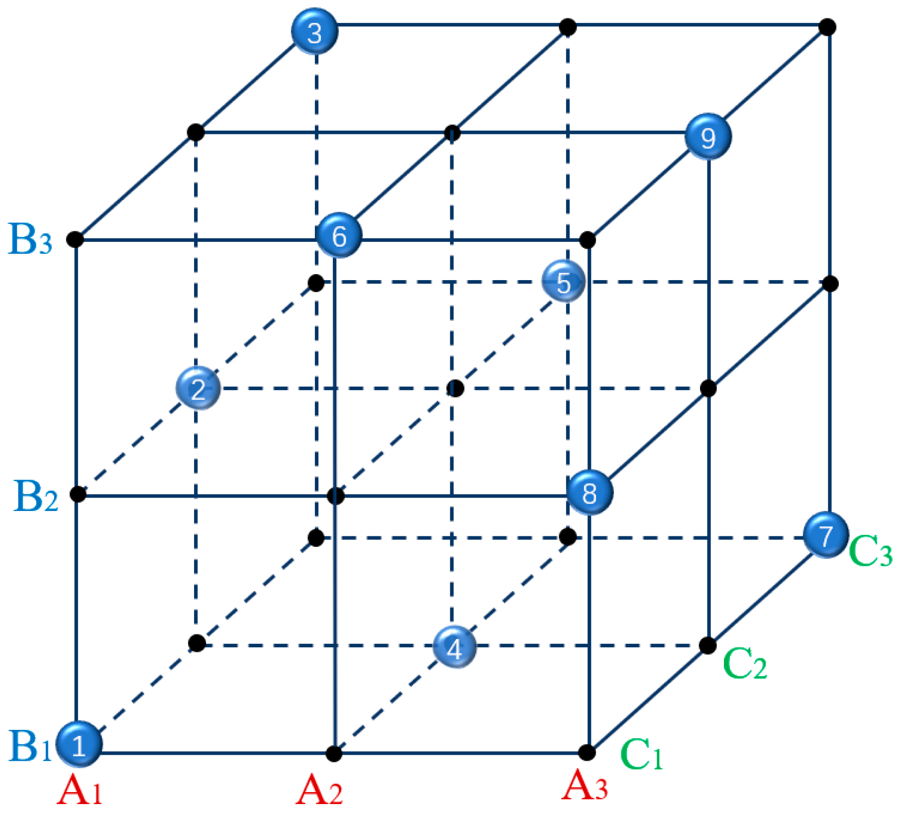
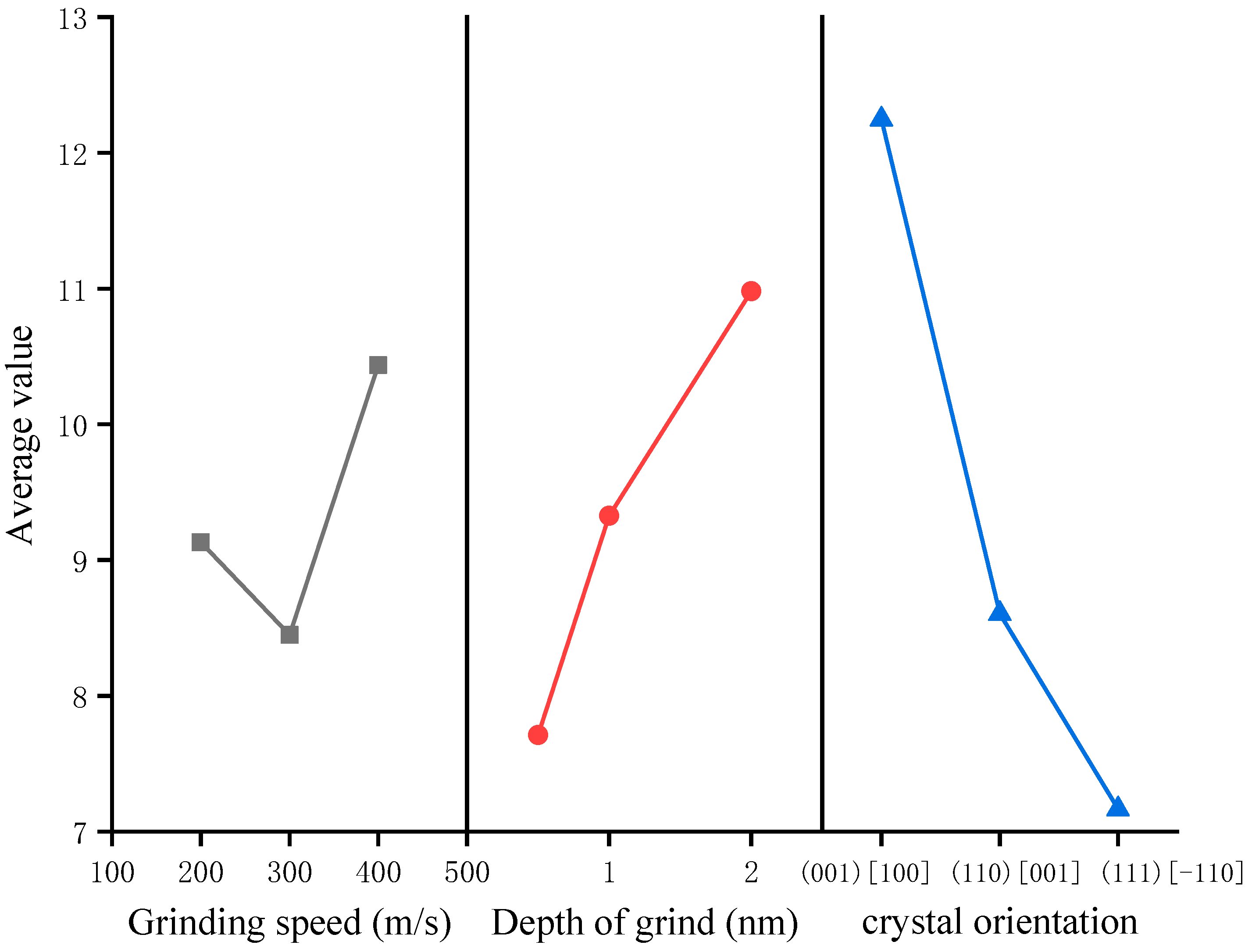
3.1. Orthogonal Calculation Results

The orthogonal test results and analysis, along with aanalysis of variance(ANOVA), are shown in Table 3 and Table 4.
As shown in Table 3, according to the range, the influence of each factor on the test results can be judged. The larger the range, the more important the corresponding factor. Therefore, machining along different crystal planes has the greatest influence on the depth of the subsurface deformation layer, which is a significant factor, followed by the grinding depth, while the grinding speed has the smallest influence. The sum of squared deviations in Table 4 also shows the same result.
According to the average values of the index results corresponding to each factor and each level, effect curves were plotted, as shown in Figure 3. It can be observed that the depth of the subsurface deformation layer was proportional to the grinding depth, that the subsurface deformation-layer depth had no linear relationship to the grinding speed, and that the subsurface deformation-layer depth was smallest when grinding along the (111) crystal surface. The optimal parameter combination for each factor could be determined. From average value 1, average value 2 and average value 3 in Table 3, it could be concluded that when the minimum depth of the subsurface deformation layer is the goal, the optimal combination of parameters is A2B1C3.

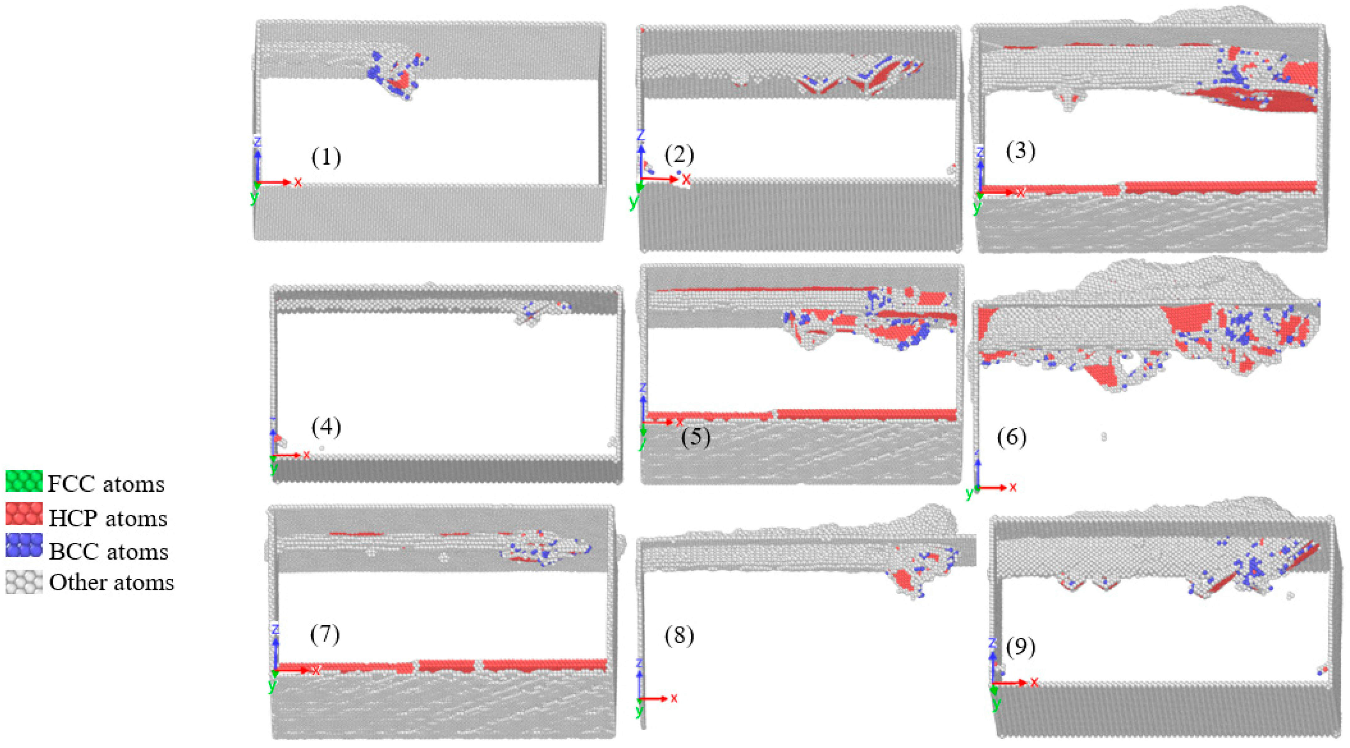
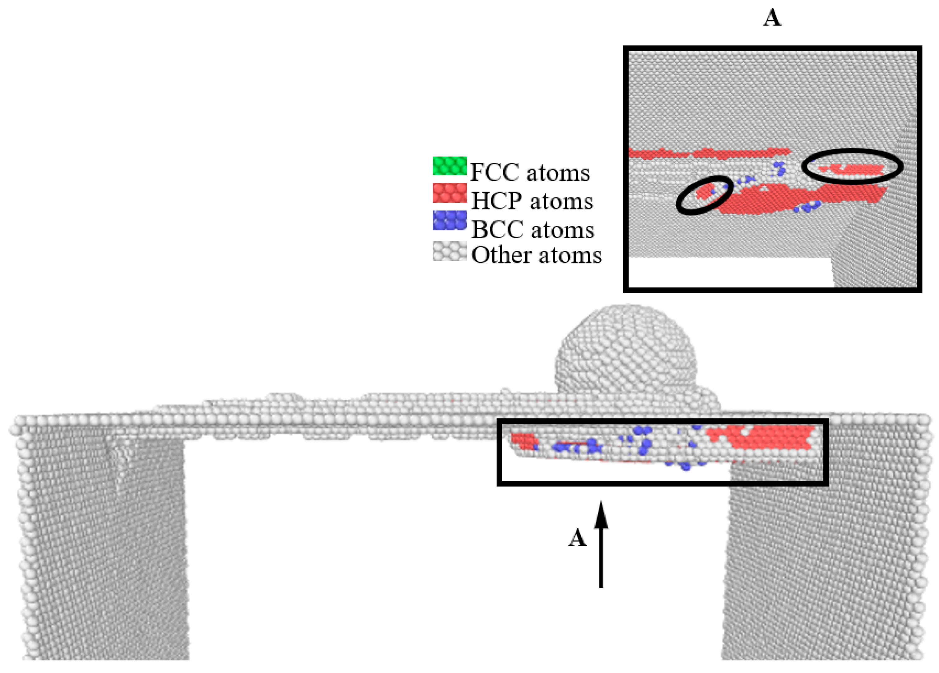
3.2. Subsurface Defects

Figure 4 shows the common neighbor analysis (CAN) of nine test groups of workpieces after nanogrinding. In order to facilitate observation, FCC atoms and tool atoms are removed. Stacking defects are usually found on the (111) and (11-1) planes while grinding on the (100) plane. The stacking fault was at an angle of 45° to the tool feed direction, as shown in Figure 4(1,6,8). The (110) surface was exposed to the grinding surface, and the stacking fault was also in the same direction, as shown in Figure 4(2,9). The stacking faults that resulted from the tool being ground on the (111) surface are shown in Figure 4(3,5,7).
Since monocrystalline nickel is an FCC crystal, its slip plane is {111} [30]. Therefore, when the (111) plane was processed, since the {111} plane in the slip system was parallel to the (111) plane, a large number of stacking faults parallel to the machined surface were generated, which reduced the downward deformation of the deformation to a certain extent, so that the depth of the subsurface deformation layer of the workpiece became smaller during (111) grinding.

3.3. Optimal Combination Simulation

MD simulation was carried out for the optimal parameter combination A2B1C3, and the deformation of the monocrystalline nickel subsurface is shown in Figure 5. By performing CNA on the simulated workpiece, the red atoms in Figure 5 were determined as having HCP structures and the blue atoms as having BCC structures, while the green FCC atoms were removed for the convenience of observation. When the tool was processed along the (111) plane, due to the shearing and extrusion action of the tool, the subsurface atoms of the workpiece that interacted with the tool were damaged. The original FCC unit cell structure was destroyed, forming a stacking-fault structure dominated by the HCP structure. Since the monocrystalline nickel was of FCC structure, its slip-plane family was {111}, so the formed stacking fault was parallel to the upper surface of the workpiece.
Due to the existence of the stacking-fault structure parallel to the upper surface, the stacking-fault structure in other directions could not extend downward, as shown in the inner part of the ellipse in Figure 5, which reduced the deformation depth of the subsurface of the workpiece to a certain extent.
In addition to the above qualitative analysis, the final deformed atomic coordinates were obtained by selecting the potential energy values of multiple groups of atoms, then drawing a potential energy-change curve. The subsurface deformation-layer depths of five groups of atoms were determined, and the average values were then calculated to obtain the subsurface deformation-layer degree under the optimal parameter combination, which was 5.3843 Å. This value was smaller than the deformation-layer degree values for all parameter combinations in the orthogonal tests presented in Table 3, which verifies the correctness of the optimal parameter combination.

4. Conclusions

The determination of the depth of the subsurface deformation layer after nanogrinding of monocrystalline nickel material being the research goal, an orthogonal experiment combined with molecular dynamics simulation was used to draw the following conclusions:
(a) Introducing orthogonal tests into the field of nanogrinding makes it more important to analyze the significant factors affecting the depth of the subsurface deformation layer compared to the analysis of single factors. Among the three factors of grinding speed, grinding depth and processing along different crystal planes, grinding along different crystal planes has the most significant effect on the depth of the subsurface deformation layer, followed by the effect of grinding depth, while the effect of grinding speed has the weakest effect. Therefore, when nanogrinding FCC materials, the (111) surface can be exposed to the grinding direction in order to minimize the depth of the subsurface deformation layer.
(b) The grinding depth is proportional to the depth of the subsurface deformation layer, and when grinding is performed on the (111) surface, the subsurface deformation-layer depth is minimized because the slip surface hinders the extension of dislocations to some extent.
(c) Within the limited scope of the research, when the grinding speed is 300 m/s and the grinding depth 0.5 nm, with nanogrinding along the (111) crystal plane, the depth of the subsurface deformation layer of monocrystalline nickel material is smallest. This result can provide guidance for actual machining processes.

Author Contributions

Conceptualization, J.R.; methodology, J.R.; data curation, J.R.; writing—original draft preparation, J.R.; writing—review and editing, J.R. and M.L.; funding acquisition, J.R. All authors have read and agreed to the published version of the manuscript.

Funding

This research was funded by the Taiyuan Institute of Technology Scientific Research Initial Funding grant number [2022KJ095].

Institutional Review Board Statement

Not applicable.

Informed Consent Statement

Not applicable.

Data Availability Statement

Not applicable.

Conflicts of Interest

The authors declare no conflict of interest.

References

  1. Gao, Q.; Gong, Y.; Zhou, Y.; Wen, X. Experimental study of micro-milling mechanism and surface quality of a nickel-based single crystal superalloy. J. Mech. Sci. Technol. 2017, 31, 171–180. [Google Scholar] [CrossRef]
  2. Wu, Y.; Xiang, J.; Yang, C.; Lu, W.; Lieber, C.M. Single-crystal metallic nanowires and metal/semiconductor nanowire heterostructures. Nature 2004, 430, 61. [Google Scholar] [CrossRef]
  3. Li, Z.; Yan, Y.; Wang, J.; Geng, Y. Molecular dynamics study on tip-based nanomachining: A review. Nanoscale Res. Lett. 2020, 15, 1–12. [Google Scholar] [CrossRef]
  4. Herrer, L.; Martín, S.; Cea, P. Nanofabrication techniques in large-area molecular electronic devices. Appl. Sci. 2020, 10, 6064. [Google Scholar] [CrossRef]
  5. Kim, M.; Kim, M.K. Four-dimensional nanofabrication for next-generation optical devices. J. Korean Phys. Soc. 2022, 81, 516–524. [Google Scholar] [CrossRef]
  6. Liu, B. Research on Nanometer Cutting Mechanism Based on Scanning Electron Microscope; Tianjin University: Tianjin, China, 2015. [Google Scholar]
  7. Meng, B.; Yuan, D.; Zheng, J.; Qiu, P.; Xu, S. Tip-based nanomanufacturing process of single crystal SiC: Ductile deformation mechanism and process optimization. Appl. Surf. Sci. 2020, 500, 144039. [Google Scholar] [CrossRef]
  8. Yan, Y.; Li, Z.; Jia, J.; Wang, J.; Geng, Y. Molecular dynamics simulation of the combination effect of the tip inclination and scratching direction on nanomachining of single crystal silicon. Comput. Mater. Sci. 2021, 186, 110014. [Google Scholar] [CrossRef]
  9. Eder, S.J.; Leroch, S.; Grützmacher, P.G.; Spenger, T.; Heckes, H. A multiscale simulation approach to grinding ferrous surfaces for process optimization. Int. J. Mech. Sci. 2021, 194, 106186. [Google Scholar] [CrossRef]
  10. Eder, S.J.; Rodríguez Ripoll, M.; Cihak-Bayr, U.; Dini, D.; Gachot, C. Unraveling and mapping the mechanisms for near-surface microstructure evolution in CuNi alloys under sliding. ACS Appl. Mater. Interfaces 2020, 12, 32197–32208. [Google Scholar] [CrossRef]
  11. Eder, S.J.; Grützmacher, P.G.; Rodríguez Ripoll, M.; Dini, D.; Gachot, C. Effect of temperature on the deformation behavior of copper nickel alloys under sliding. Materials 2020, 14, 60. [Google Scholar] [CrossRef]
  12. Wu, Z.; Zhang, L.; Yang, S. On the deformation mechanism of 6H-SiC under the nanogrinding of multiple abrasive grains. Tribol. Int. 2023, 179, 108119. [Google Scholar] [CrossRef]
  13. Karkalos, N.E.; Markopoulos, A.P. Determination of the efficiency of hot nano-grinding of mono-crystalline fcc metals using molecular dynamics method. Micromachines 2022, 13, 415. [Google Scholar] [CrossRef]
  14. Markopoulos, A.P.; Karkalos, N.E.; Papazoglou, E.L. Meshless methods for the simulation of machining and micro-machining: A review. Arch. Comput. Methods Eng. 2019, 27, 831–853. [Google Scholar] [CrossRef]
  15. Xu, F.; Fang, F.; Zhang, X. Study on surface generation in nano-cutting by large-scale molecular dynamics simulation. Int. J. Adv. Manuf. Technol. 2019, 104, 4325–4329. [Google Scholar] [CrossRef]
  16. Wang, J.; Fang, F.; Li, L. Cutting of graphite at atomic and close-to-atomic scale using flexible enhanced molecular dynamics. Nanomanufacturing Metrol. 2022, 5, 240–249. [Google Scholar] [CrossRef]
  17. Dai, L.; Chen, G.; Shan, Z. Study on ultra-high speed nano-grinding of monocrystalline copper with V-shaped diamond abrasive grains based on molecular dynamics method. Diam. Relat. Mater. 2021, 111, 108224. [Google Scholar] [CrossRef]
  18. Zhang, S.; Cheng, X.; Chen, J. Surface deformation, phase transition and dislocation mechanisms of single crystalline 6H-SiC in oblique nano-cutting. Appl. Surf. Sci. 2022, 588, 152944. [Google Scholar] [CrossRef]
  19. Zhao, P.; Zhao, B.; Pan, J.; Wu, J. Nano-grinding process of single-crystal silicon using molecular dynamics simulation: Nano-grinding parameters effect. Mater. Sci. Semicond. Process. 2022, 143, 106531. [Google Scholar] [CrossRef]
  20. Plimpton, S.J. Fast parallel algorithms for short-range molecular dynamics. J. Comput. Phys. 1995, 117, 1–19. [Google Scholar] [CrossRef]
  21. Stukowski, A. Visualization and analysis of atomistic simulation data with OVITO-the open visualization tool. Model. Simul. Mater. Sci. Eng. 2010, 18, 015012. [Google Scholar] [CrossRef]
  22. Markopoulos, A.P.; Savvopoulos, I.K.; Karkalos, N.E.; Manolakos, D.E. Molecular dynamics modeling of a single diamond abrasive grain in grinding. Front. Mech. Eng. 2015, 10, 168–175. [Google Scholar] [CrossRef]
  23. Eder, S.J.; Cihak-Bayr, U.; Bianchi, D.; Feldbauer, G.; Betz, G. Thermostat influence on the structural development and material removal during abrasion of nanocrystalline ferrite. ACS Appl. Mater. Interfaces 2017, 9, 13713–13725. [Google Scholar] [CrossRef] [PubMed]
  24. Shiari, B.; Miller, R.E.; Klug, D.D. Multiscale simulation of material removal processes at the nanoscale. J. Mech. Phys. Solids 2007, 55, 2384–2405. [Google Scholar] [CrossRef]
  25. Mishin, Y.; Farkas, D.; Mehl, M.J.; Papaconstantopoulos, D.A. Interatomic potentials for monoatomic metals from experimental data and ab initio calculations. Phys. Rev. B 1999, 59, 3393. [Google Scholar] [CrossRef]
  26. Lin, Z.; Huang, J.; Jeng, Y. 3D nano-scale cutting model for nickel material. Mater. Process. Technol. 2007, 192–193, 27–36. [Google Scholar] [CrossRef]
  27. Ren, J.; Hao, M.; Lv, M.; Wang, S.; Zhu, B. Molecular dynamics research on ultra-high-speed grinding mechanism of monocrystalline nickel. Appl. Surf. Sci. 2018, 455, 629–634. [Google Scholar] [CrossRef]
  28. Zhang, J. Research on the Formation Mechanism of Surface Layer of Crystalline Copper Nanomachined Based on Molecular Dynamics; Harbin Institute of Technology: Harbin, China, 2011. [Google Scholar]
  29. Zhang, J.J.; Sun, T.; Yan, Y.D.; Liang, Y.C.; Dong, S. Molecular dynamics simulation of subsurface deformed layers in AFM-based nanometric cutting process. Appl. Surf. Sci. 2008, 254, 4774–4779. [Google Scholar] [CrossRef]
  30. Ren, J.; Liang, G.X.; Lv, M. Effect of different crystal orientations on the surface integrity during nanogrinding of monocrystalline nickel. Model. Simul. Mater. Sci. Eng. 2019, 27, 075007. [Google Scholar] [CrossRef]
Figure 1. MD simulation nanogrinding model.
Coatings 13 00410 g001
Figure 2. Orthogonal schematic. (1–9 are the nine representative test groups selected from orthogonal test L9(34).
Coatings 13 00410 g002
Figure 3. Effectiveness curve graph.
Coatings 13 00410 g003
Figure 4. Subsurface damage of workpiece after grinding under different conditions in nine groups. (1–9 correspond to 9 test groups of orthogonal experiment respectively).
Coatings 13 00410 g004
Figure 5. The subsurface situation under the optimal combination of parameters. (The A is the direction view of the rectangular framed part, the projection direction is from the bottom to up).
Coatings 13 00410 g005
Table 1. MD simulation parameters for grinding along different crystal directions.
ConfigurationMD Simulation Conditions
Potential usedNi-Ni:EAM [25], Ni-C:Morse [26]
Grinding grain dimension, r/nm2
Workpiece dimension21.2 nm × 21.2 nm × 10.6 nm
Numbers of atoms in various crystal orientation workpiecesCrystal set-upNo. of atoms
(110)[001]437,155
(111)[ 1 ¯ 10]440,530
(001)[100]446,551
Grinding speed, v/m/s200/300/400
Depth of grind, H/nm 0.5/1/2
Time step, t/fs1
Initial temperature, T/K293
Table 2. Four-factor, three-level orthogonal test table.
LevelFactor
Grinding Speed, v/m/s
A
Depth of Grind, H/nm
B
Crystal Orientation
C
Blank Column
D
12000.5(001)[100]
23001.0(110)[001]
34002.0(111)[ 1 ¯ 10]
Table 3. Orthogonal test results and analysis.
Test GroupGrinding Speed,
v/(m/s)
A
Grinding Depth,
H/nm
B
Crystal Orientation
C
Blank Column
D
Deformation Depth,
S/Å
111119.58040
212229.14992
313338.66310
421236.15190
522315.43415
6231213.76130
731327.40060
8321313.39560
9332110.51295
average value 19.1317.71112.2468.509
average value 28.4499.3278.60510.104
average value 310.43610.9797.1669.404
range1.9873.2685.0801.595
Table 4. ANOVA table for the orthogonal test.
FactorDeviation Sum of SquaresDegrees of FreedomF RatioF Critical ValueSalience
Grinding speed6.11821.5969.000
Grinding depth16.02224.1799.000
Crystal orientation41.131210.7289.000*
Deviation3.832
* significant factors.
Disclaimer/Publisher’s Note: The statements, opinions and data contained in all publications are solely those of the individual author(s) and contributor(s) and not of MDPI and/or the editor(s). MDPI and/or the editor(s) disclaim responsibility for any injury to people or property resulting from any ideas, methods, instructions or products referred to in the content.

