Article

Enhanced Corrosion−Resistance of AlTiCrFeMoSi High−Entropy Alloy Coating by Magnetron Sputtering

1
Collaborative Innovation Center of Steel Technology, University of Science and Technology Beijing, Beijing 100083, China
2
College of Materials Science and Engineering, Hunan University, Changsha 410082, China
3
Anhui Engineering Research Center for High Efficiency Intelligent Photovoltaic Module, Chaohu University, Hefei 238000, China
*
Author to whom correspondence should be addressed.
Coatings 2023, 13(2), 332; https://doi.org/10.3390/coatings13020332
Submission received: 30 December 2022 / Revised: 26 January 2023 / Accepted: 26 January 2023 / Published: 1 February 2023
(This article belongs to the Special Issue Advanced High-Entropy Materials and Coatings)

Abstract

:
The amorphous AlTiCrFeMoSi high entropy alloy (HEA) coating with high hardness (11.88 GPa) is successfully deposited on T91 substrate by the magnetron sputtering method. Both T91 steel and as−deposited AlTiCrFeMoSi coating samples are exposed to a static liquid lead−bismuth eutectic (LBE) at 550 °C for up to 2000 h. The coating exhibits excellent corrosion resistance against lead−bismuth eutectic (LBE) compared with the uncoated T91 steel. The results show that the AlTiCrFeMoSi HEA coating has great potential in LBE−cooled fast reactor application.

1. Introduction

Lead−cooled fast neutron reactors are expected to become advanced nuclear power reactors for industrial demonstration and commercial application and should be cooled by liquid lead−bismuth eutectic LBE), because its superior neutronics, thermal hydraulics, and chemical inertness [1,2]. T91 is considered to be candidate structural material for lead−cooled fast reactors because of its high corrosion resistance and extreme toughness. It is well known that the corrosion mechanism of LBE on T91 steel is mainly dissolution corrosion and oxidation corrosion. When it is in a low oxygen concentration in LBE, the T91 can be damaged by dissolution of the major alloying components; when in an oxygen containing LBE, oxidation plays a major role in the corrosion process.
Surface coating technology is one of the methods considered to be capable of solving the corrosion resistance problem of the next generation of nuclear power reactors [3]. Many coating materials have been designed and prepared for corrosion studies in LBE environments, such as high al−containing coatings (FeAl, FeCrAl, FeCrAlY) [4,5] and ceramic coatings (SiC, Ti3SiC2, Al2O3, TiC, TiAlN, Cr/TiAlN, CrN, TiN and TiSiN) [6,7,8,9,10,11,12].
High entropy alloy (HEA) are a new class of alloys that contain five or more elements in equal or near−equal ratios. High entropy alloys have attracted many researchers due to their excellent properties. In the field of LBE corrosion, many researchers’ attention has been focused on research on bulk materials (Al0.7CoCrFeNi, AlCrFeNiCu, AlCrFeNiTi, AlCrFeNiNb, et al.) [13,14], and some excellent research results have been achieved. Bulk high−entropy alloys, however, are expensive and difficult to form, especially when these alloys contain LBE corrosion−resistant elements such as Mo, Cr, and Ti. On the other hand, high−entropy alloy coatings have excellent properties similar to those of bulk high−entropy alloys. Most important, many preparation processes can be used to fabricate high−entropy alloy coatings. The corrosion behavior and mechanism of high−entropy alloy coatings in high−temperature LBE are expected to become the next research hotspot [3,15].
What is most important for LBE corrosion resistance is the rapid formation of stable and dense passivation film. The Al−rich, Si−rich, and Cr−rich oxide films can be formed at low oxygen concentrations, and the addition of Cr, Si, and Ti can reduce the oxidation rate of the material [16,17,18]. Elemental Mo is almost insoluble in LBE, and it can increase atomic size mismatch (~0.136 nm), leading to increased lattice distortion and favoring the formation of nanocrystalline or amorphous structures [19]. The addition of Fe can improve the adhesion of the coating and the substrate. While other candidate elements, such as Mn, Ni, Ta, and Cu have high solubility in LBE, Zr has a large atomic size (~0.160 nm) and Nb has high enthalpy for mixing with other elements. Therefore, a novel AlTiCrFeMoSi high entropy alloy coating has been designed and deposited on T91 steel substrate by using magnetron sputtering technology. After the coating is prepared, its microstructure, mechanical properties and corrosion resistance of the coating under static LBE are investigated systematically.

2. Materials and Methods

The AlTiCrFeMoSi HEA coating is deposited on T91 substrate by DC magnetron sputtering technology. The sputtering target is prepared by a powder metallurgy process after ball milling and mixing of six single element powders. Here the element powders are Al, Ti, Cr, Fe, Mo and Si (all with 99.95% purity). The target size is 76.2 mm in diameter and 5 mm in thickness.
Before the formal sputtering, the target and the substrate are ion−cleaned for 15 min at a 1.8 Pa working pressure, an argon flow rate of 60 sccm, and sputtering power of 50 W to remove the surface oxide and other contamination. During the deposition, the base pressure of the sputtering chamber is 4 × 10⁻⁴ Pa, while the substrate temperature, the Ar gas flow rate and sputtering pressure are maintained at 300 °C, 30 sccm and 0.5 Pa, respectively. The coatings are prepared by sputtering for 4.5 h at a sputtering power of 200 W and a bias voltage of 100 V.
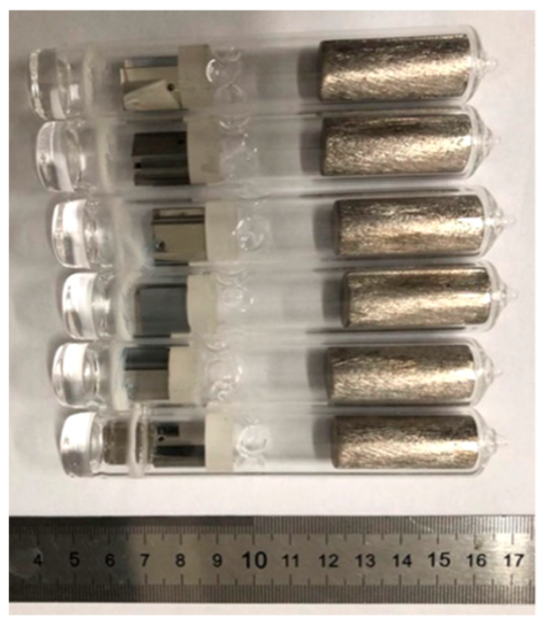
The LBE corrosion tests are performed with homemade equipment composed of a static quartz tube. Figure 1 shows the shape of the quartz tube with the inner diameter of 18 mm and the outer diameter of 20 mm, and the length of the quartz tube is 100 mm. The T91 samples with length and width of 14 mm and 10 mm respectively, and samples of 2−mm thickness are put in one side of the quart tube and the solid 45Pb−55Bi wt.% Pb/Bi cylinders (99.99% purity) with a total mass of 220 g are put in the other side. The vacuum of the quartz tube is pumped to 1 × 10⁻³ Pa by a molecular pump and sealed by an acetylene flame. Therefore the length of the quartz tube must be long enough to avoid burning the lead−bismuth alloy, such as 100 mm. The density of LBE is 10.2 g/cm3, which is higher than that of steel 7.85 g/cm3. Therefore, when the temperature exceeds 400 K, the Pb−Bi alloy melts in order to ensure that the LBE can submerge the sample and prevent it from floating up. The solid lead−bismuth cylinders are 14 mm in diameter and 35 mm in length. Then they are set on an inward depression in the quartz tube at 30 mm from the bottom and inserted a 14 mm diameter quartz plug is inserted between the sample and the depression. The physical diagram of the quartz tube is shown in Figure 2. Put the sealed quartz tube vertically into a muffle furnace with PID temperature control at 550 °C to ensure that the samples are corroded in LBE for up to 2000 h. Meanwhile, the samples of coated and non−coated steel are also tested under the same conditions. After the LBE corrosion test, the residual Pb−Bi on the surface of the samples is cleaned using a volume ratio of 1:1:1 CH3CH2OH, CH3COOH and H2O2.
The phase structure of the HEA coatings is characterized by X-ray diffraction (XRD, Smartlab 9 KW, Tokyo, Japan). Because the coating thickness is in the micron range, a grazing incidence XRD is adopted in order to exclude the influence of the substrate. A grazing incidence angle of 1° and a scanning speed of 4°/min are used. The surface morphologies and cross−sectional morphologies of the coatings are observed using a field emission scanning electron microscope (SEM, ZEISS SUPRA55, Oberkochen, Germany) and atomic force microscopy (AFM, Smart SPM 4000, Kyoto, Japan). When observing the cross−section morphology of the sample, the cross−section of the sample is embedded with epoxy resin, and the surface is sprayed with gold after grinding and polishing for subsequent observation. The chemical composition is analyzed by Electron energy dispersive X-ray spectrometry (EDS). A nanoindenter (Nano Indenter XP, Billerica, MA, USA) is used to measure the nanohardness of the coatings. Nanoindentation uses a Berkovich type diamond indenter with a maximum load of 700 mN and a maximum stroke of 40 μm. In order to eliminate the influence of the substrate, the substrate and coating are measured for hardness using a single stiffness measurement and a continuous stiffness measurement, respectively. The single stiffness measurement uses the unloading curve to obtain the contact stiffness. Each indentation cycle can only obtain a hardness at the maximum indentation depth. The continuous stiffness measurement method can directly obtain the contact stiffness of each data point collected during the press−in process corresponding to the press−in depth. Then, the hardness is calculated as a continuous function of the press−in depth, which is suitable for thin coatings [20].

3. Results and Discussion

3.1. Microstructure

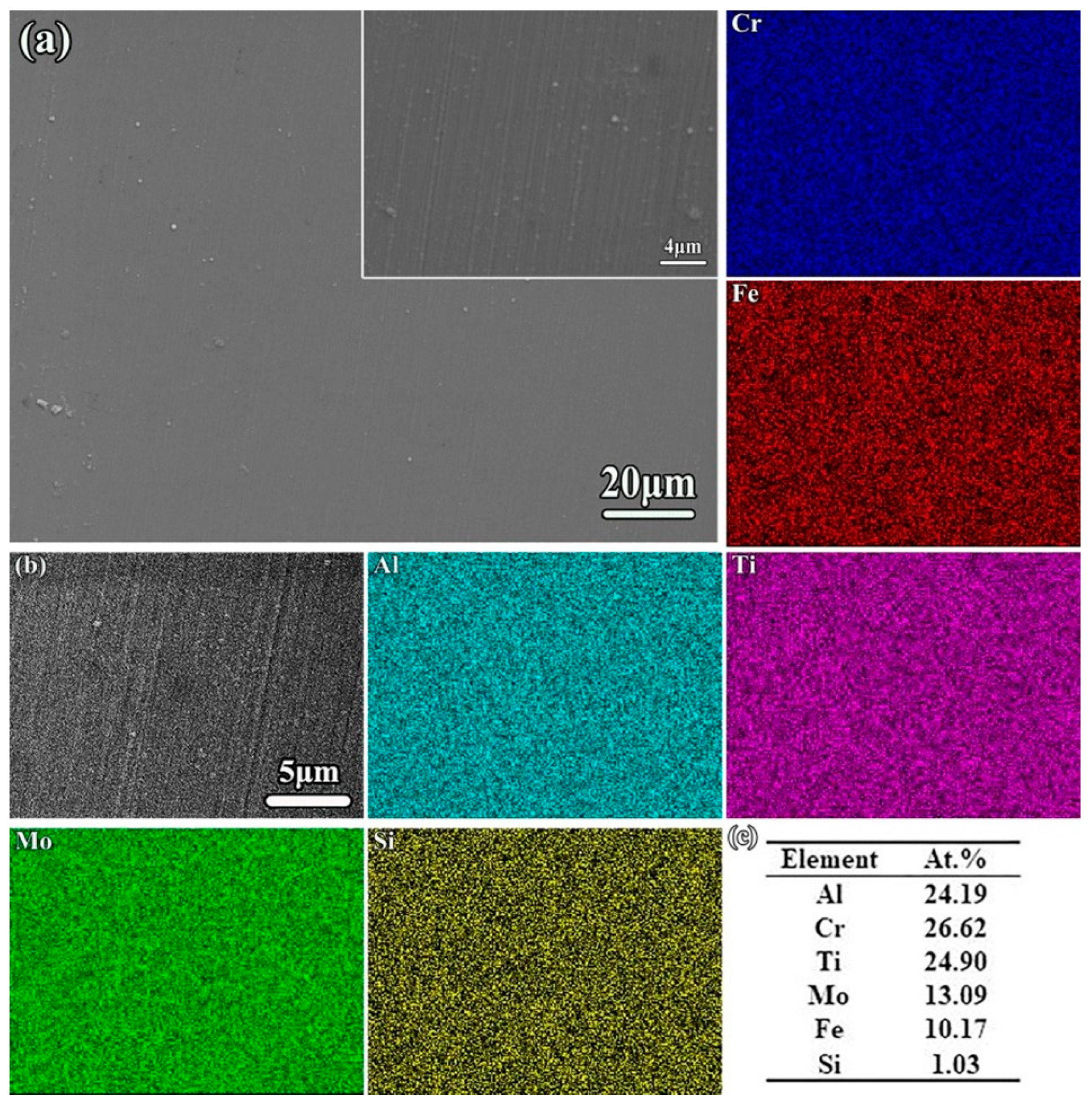
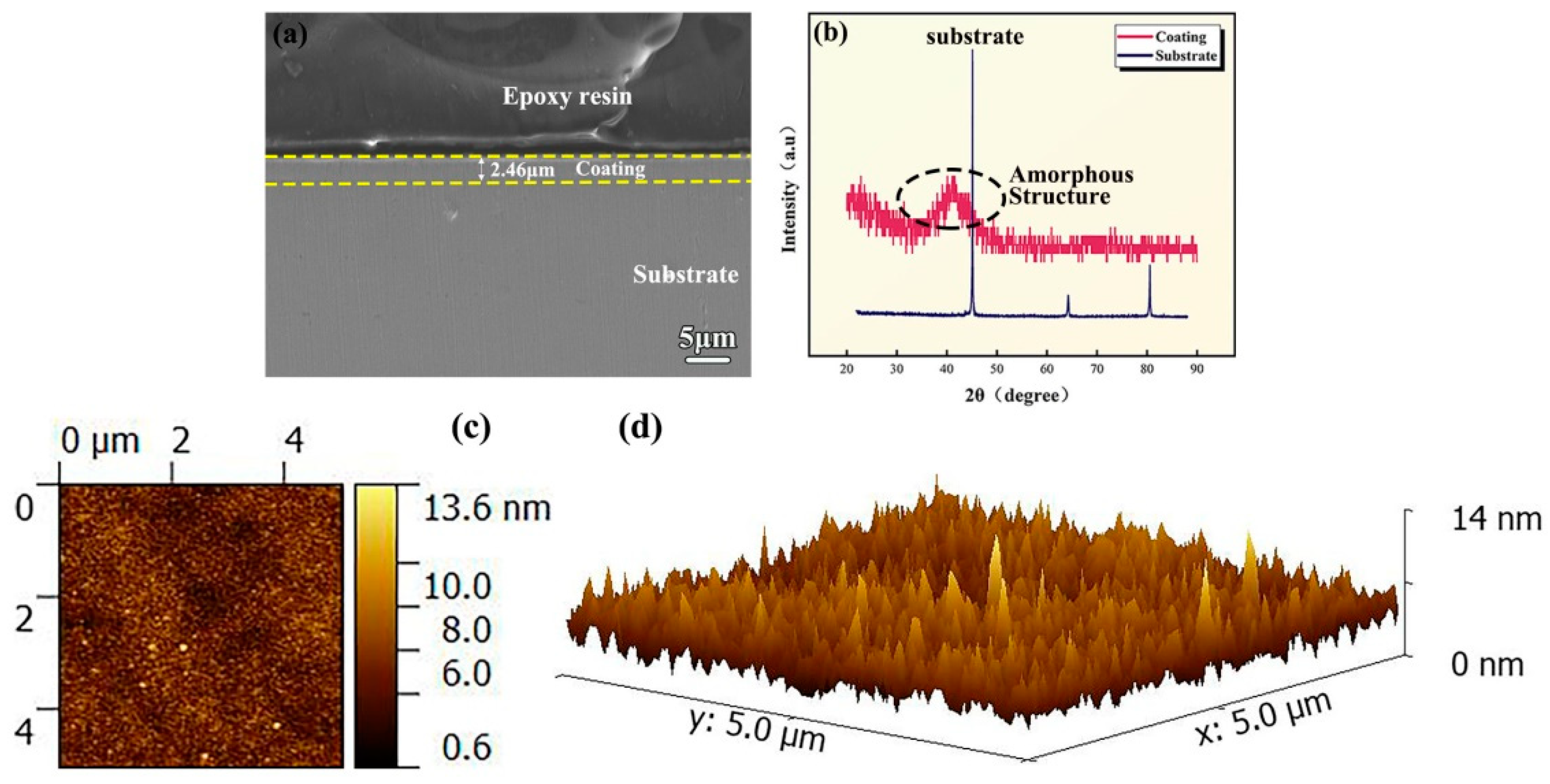
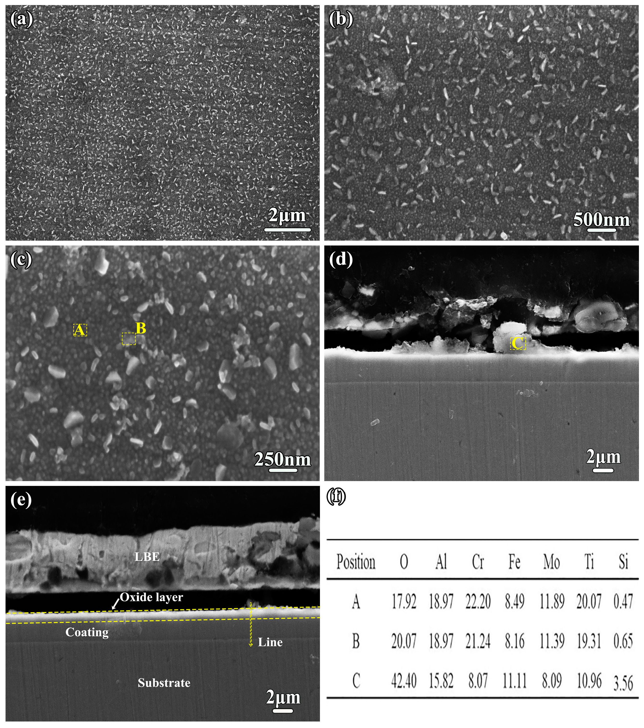
Figure 3a–c show the surface morphology SEM image of the as−deposited AlTiCrFeMoSi coating and surface EDS results on the T91 substrate, respectively. It can be seen that no cracks and holes are found in the coating. Moreover, a homogeneous distribution of the Al, Cr, Fe, Ti, Si, and Mo element in the coating was confirmed by EDS, indicating that the prepared high entropy alloy coating was of good quality. The high magnification in the upper right corner of Figure 3 shows some shallow linear scratches, which are from the polished substrate. The cross−sectional SEM image of the as−deposited AlTiCrFeMoSi coating is presented in Figure 4a and exhibits uniform thickness of approximately 2.46 μm. One can see that the interface of the coating is flat and straight and no cracks are observed between the substrate and the coating. The phase structure of the AlTiCrFeMoSi HEA coating is analyzed by XRD, as shown in Figure 4b. It shows that the coating has only one wide diffraction peak at a diffraction angle 2θ = 41.5°, which is similar to the AlTiVCrSi HEA coating prepared by Zheng et al [21]. Therefore, it can be concluded that the high−entropy alloy coating prepared in this work has a completely amorphous structure, which is attributed to the rapid cooling rate of magnetron sputtering and the large difference in atomic size. It has been reported in the literature [19,22,23] that high entropy alloy coatings can hinder the diffusion of elements during rapid cooling, preventing grain nucleation and growth. To increase the number of high−entropy alloy components and the huge difference in atomic size makes the high−entropy alloy system more chaotic, which is beneficial to increase the degree of atomic disordered stacking, the crystallization resistance, and to improve the glass forming ability. The completely amorphous AlTiCrFeMoSi HEA coating has a higher LBE corrosion resistance due to the lack of grain boundaries for element diffusion and the inherently sluggish diffusion effect of the HEA coatings. The more microscopic surface morphology of the coating is characterized by AFM, as shown in Figure 4c,d, which shows the 2D and 3D morphologies of the coating respectively. From Figure 4, one can see that the coating has a dense and smooth surface (Ra = 1.15 nm).

3.2. Mechanical Properties

The nanohardnesses of the AlTiCrFeMoSi HEA coating and T91 steel substrate are tested by nanoindentation. Five indentation experiments are performed for five substrate and coating samples, respectively, all with a maximum indentation depth of 2000 nm. The load−displacement (P−h) curve of the T91 substrate is shown in Figure 5a, and the nanohardness at 2000 nm depth of the substrate is obtained by analyzing the unloading curve. The coating is measured using the continuous stiffness method, and the load−displacement curve is shown in Figure 5b; there is no unloading curve. A section where the hardness varies smoothly with the depth of indentation is taken as coating nanohardness, as shown in the black dotted bordered rectangle in Figure 5b, the depth is approximately 500 nm as shown in Figure 5c. The nanohardness of the T91 steel substrate is calculated as 3.28 GPa. This is similar to the 3.15 GPa measured by Hu et al. [24]. The nanohardness for the AlTiCrFeMoSi HEA coating is 11.88 GPa. The nanohardness of the AlTiCrFeMoSi HEA coating is 2.62 times higher than that of the substrate (3.28 GPa). There are three reasons for the high nanohardness of the high entropy alloy coating in this work. First, the principal elements have significant differences in the atomic size, chemical bond, and crystal structure in high entropy alloys, which will result in serious lattice distortion [25,26]. Severe lattice distortion will lead to atomic migration from equilibrium positions and generate strain energy, which results in greater resistance to dislocation motion and a significant increase in solid solution strengthening. Meanwhile, when shear stress is applied to crystal alloy, dislocations will slip along certain crystal orientations at specific interfaces, but the amorphous coatings do not have dislocations, grain boundaries, stacking fault or other defects [27]. Therefore, the atoms move in a collective manner showing shear deformation when the atoms in an amorphous coating are stressed, which makes it necessary for the amorphous coating to have a higher stress in order to deform and for the coating to exhibit a higher hardness. Moreover, the atomic diffusion coefficient in high−entropy alloy is lower than that of reference metals and the atomic sluggish diffusion in high−entropy alloys [28,29], which can effectively hinder the formation of shear bands and improve the hardness of the coating.

3.3. LBE Corrosion Test

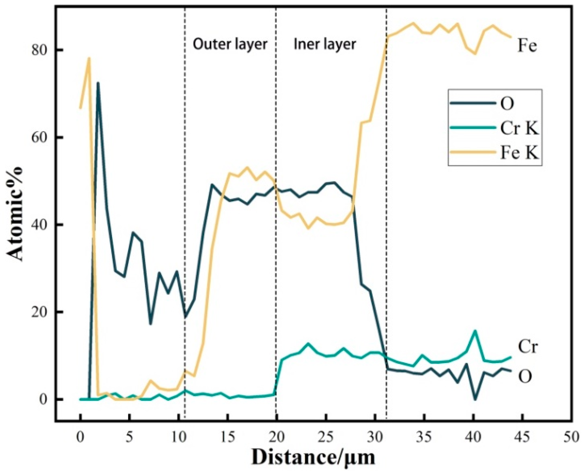
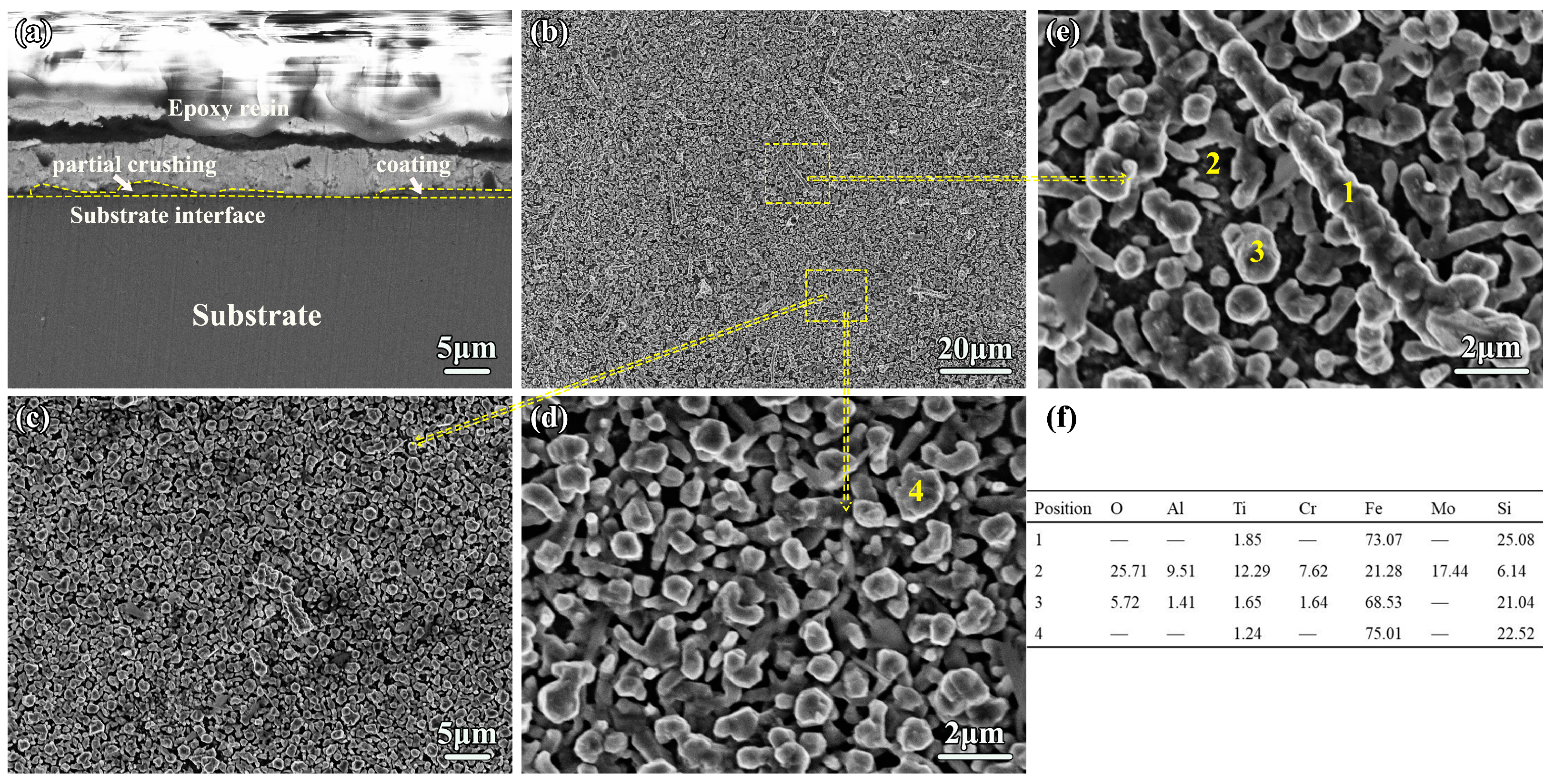
Figure 6 shows SEM cross sectional and surface images of the uncoated T91 steel substrate at 550 °C after 500 h static LBE corrosion. It can be seen that the T91 surface oxide film consists of a large number of stripy oxides with the presence of pores, and it shows that the substrate surface is roughened by LBE corrosion. Meanwhile, the EDS line scanning of the uncoating T91 substrate exposed to LBE at 550 °C for 500 h is shown in Figure 7. The result indicates that the surface oxide film (~19 μm) of the T91 substrate consists of a double layer after 500 h exposure to LBE at 550 °C. The Pb−Bi showed signs of penetration of the oxide film by micro−area EDS analysis of the oxide film on the substrate surface. Figure 8 shows SEM cross sectional and surface images of the as−deposited AlTiCrFeMoSi HEA coating. It can be seen that the surface oxide film consists of a large number of fine spherical particles. The coarse white oxides are analyzed by micro−area EDS, and both the fine black particles are the same coating composite oxide. Figure 8d,e shows that the substrate interface is straight and the high−entropy alloy coating still maintains coating integrity after 500 h of LBE corrosion, as shown by the yellow dotted straight line. The EDS line scanning of the AlTiCrFeMoSi HEA coating exposed to LBE at 550 °C for 500 h is shown in Figure 9. It indicates that the thickness of AlCrFeMoTiSi high−entropy alloy coating is about 1.8 μm, and combined with Figure 8d,e the uniform oxide layer on the coating surface is less than 1 μm. It shows that the high entropy alloy coating can effectively protect the substrate when samples are exposed to a static LBE at 550 °C after 500 h.
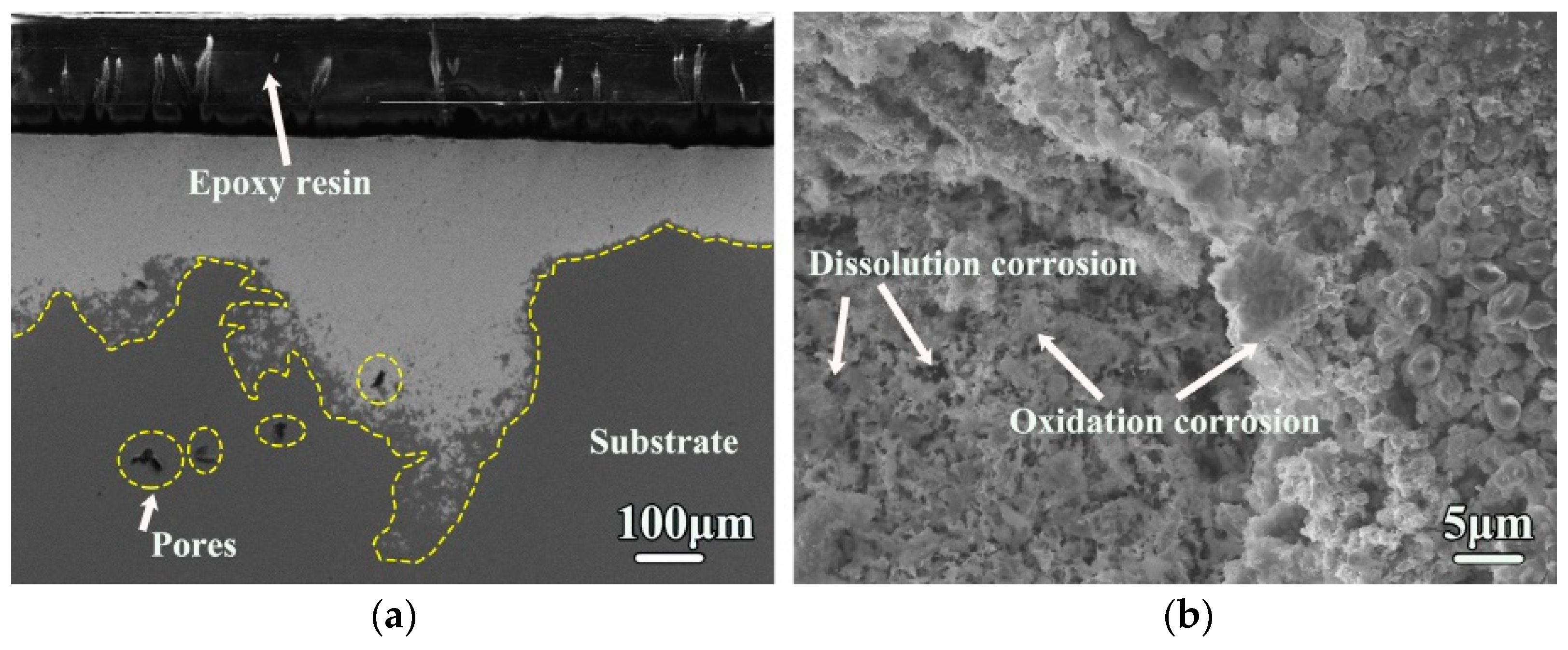
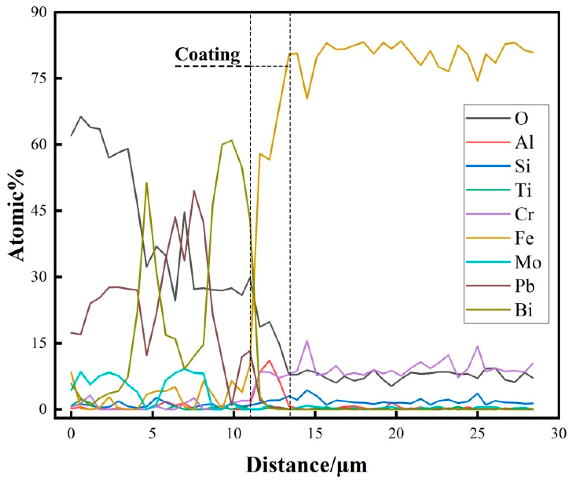
Figure 10 shows SEM cross−sectional and surface images of the uncoated T91 steel substrate at 550 °C after 2000 h LBE corrosion, indicating that the major element of T91 steel substrate dissolves significantly and many holes are produced, resulting in the penetration of Pb−Bi into the sunstrate. The Pb−Bi penetration distance is more than 200 μm, which is the same as marked by the yellow curve in Figure 10a. Figure 10b shows that there are many holes and oxidation products on the surface, which is similar to that of Bian et al. [30]. Long−term corrosion at low oxygen concentrations causes a strong dissolution corrosion of the material. It can also be found that many holes in Figure 10a are aggregated, as shown in the yellow circle. It is speculated that the formation of the hole is caused by the penetration of Pb−Bi into the substrate or caused in the process of substrate preparation. Figure 11 shows SEM cross−sectional and surface images of the as−deposited AlTiCrFeMoSi HEA coating. Figure 11a shows that the substrate interface is straight and there are still some coating residues on the surface. Figure 11b–e shows that there are still more dense oxide particles on the surface of the coating. Figure 11f further explains the above content. One can see that the coating exhibits excellent corrosion resistance against LBE with much thinner oxides scale and lower consumption of coating compared with the uncoated T91 steel at the same corrosion conditions. Meanwhile, the EDS line scanning of the AlTiCrFeMoSi HEA coating exposed to LBE at 550 °C for 2000 h is shown in Figure 12. The result indicates that the coating elements do not diffuse and migrate significantly to the coating surface or substrate, confirming further the integrity of the coating. Although the oxygen is detected in the coating surface, no obvious oxygen signal is detected in the substrate, suggesting that the coating has excellent LBE corrosion resistance at 550 °C.

4. Conclusions

In the current work, the as deposited AlTiCrFeMoSi HEA coating contains a completely amorphous structure, and displays extreme hardness (11.88 GPa). Both the T91 sample and the AlTiCrFeMoSi HEA coating are exposed to a static liquid lead−bismuth eutectic (LBE) at 550 °C for up to 2000 h. The experimental results indicate that the T91 sample has a deeper inward penetration of LBE into the steel than that of the AlTiCrFeMoSi HEA coating. The coating exhibits excellent corrosion resistance against the LBE with much thinner oxides scale and lower consumption of coating compared with the uncoated T91 steel at the same corrosion conditions, showing that the AlTiCrFeMoSi HEA coating has great potential in LBE cooled fast reactor application.

Author Contributions

Conceptualization, B.Y.; formal analysis, B.Y. and L.Z.; investigation, L.Z., Y.S. and Q.Y.; writing−original draft preparation, L.Z.; writing−review and editing, B.Y. and L.Z.; supervision, B.Y.; project administration, B.Y., L.Z., Y.S. and Q.Y.; funding acquisition, B.Y. All authors have read and agreed to the published version of the manuscript.

Funding

This research was funded by Innovation Center of Nuclear Materials for National Defense Industry [ICNM−2021−YZ−01]; The National Natural Science Foundation of China (51901242); The Department of Education of Anhui Province [2022AH051721].

Institutional Review Board Statement

Not applicable.

Informed Consent Statement

Not applicable.

Data Availability Statement

The data underlying this article will be shared on reasonable request from the corresponding author.

Conflicts of Interest

The authors declare no conflict of interest.

References

  1. Oigawa, H.; Tsujimoto, K.; Nishihara, K.; Sugawara, T.; Kurata, Y.; Takei, H.; Saito, S.; Sasa, T.; Obayashi, H. Role of ADS in the back–end of the fuel cycle strategies and associated design activities: The case of Japan. J. Nucl. Mater. 2011, 415, 229–236. [Google Scholar] [CrossRef]
  2. Zhang, J.; Li, N. Review of the studies on fundamental issues in LBE corrosion. J. Nucl. Mater. 2008, 373, 351–377. [Google Scholar] [CrossRef]
  3. Wang, H.; Xiao, J.; Wang, H.; Chen, Y.; Yin, X.; Guo, N. Corrosion Behavior and Surface Treatment of Cladding Materials Used in High−Temperature Lead−Bismuth Eutectic Alloy: A Review. Coatings 2021, 11, 364. [Google Scholar] [CrossRef]
  4. Fetzer, R.; Weisenburger, A.; Jianu, A.; Müller, G. Oxide scale formation of modified FeCrAl coatings exposed to liquid lead. Corros. Sci. 2012, 55, 213–218. [Google Scholar] [CrossRef]
  5. Engelko, V.; Mueller, G.; Rusanov, A.; Markov, V.; Tkachenko, K.; Weisenburger, A.; Kashtanov, A.; Chikiryaka, A.; Jianu, A. Surface modification/alloying using intense pulsed electron beam as a tool for improving the corrosion resistance of steels, exposed to heavy liquid metals. J. Nucl. Mater. 2011, 415, 270–275. [Google Scholar] [CrossRef]
  6. Wa, Q.; Wu, Z.; Liu, Y.; Yang, B.; Liu, H.D.; Ren, F.; Wang, P.; Xiao, Y.Y.; Zhang, J.; Zhang, G.D. Lead−bismuth eutectic (LBE) corrosion mechanism of nano−amorphous composite TiSiN coatings synthesized by cathodic arc ion plating. Corros. Sci. 2021, 183, 109264. [Google Scholar]
  7. Rivai, A.K.; Takahashi, M. Compatibility of surface–coated steels, refractory metals and ceramics to high temperature lead–bismuth eutectic. Prog. Nucl. Energy 2008, 50, 560–566. [Google Scholar] [CrossRef]
  8. Wu, Z.; Zhao, X.; Liu, Y.; Cai, Y.; Li, J.Y.; Chen, H.; Wan, Q.; Yang, D.; Tan, J.; Liu, H.D.; et al. Lead–bismuth eutectic (LBE) corrosion behavior of AlTiN coatings at 550 and 600 °C. J. Nucl. Mater. 2020, 539, 152280. [Google Scholar] [CrossRef]
  9. Miorin, E.; Montagner, F.; Zin, V.; Giuranno, D.; Ricci, E.; Pedroni, M.; Spampinato, V.; Vassallo, E.; Deambrosis, S.M. Al rich PVDprotective coatings: A promising approach to prevent T91 steel corrosion in stagnant liquid lead. Surf. Coat. Technol. 2019, 377, 124890. [Google Scholar] [CrossRef]
  10. Barshilia, H.C.; Prakash, M.S.; Jain, A.; Rajam, K.S. Structure, hardness and thermal stability of TiAlN and nanolayered TiAlN/CrNmultilayer films. Vacuum 2005, 77, 169–179. [Google Scholar] [CrossRef]
  11. Glasbrenner, H.; Grschel, F. Exposure of pre–stressed T91 coated with TiN, CrN and DLC to Pb–55.5Bi. J. Nucl. Mater. 2006, 356, 213–221. [Google Scholar] [CrossRef]
  12. Chakraborty, P.; Ghosh, A.; Dey, G.K. Compatibility of Lead−Bismuth Eutectic with SiC–Coated Graphite at Elevated Temperature. Metall. Mater. Trans. B. 2017, 48, 1–5. [Google Scholar] [CrossRef]
  13. Gong, X.; Xiang, C.; Auger, T.; Chen, J.; Liang, X.; Yu, Z.; Short, M.P.; Song, M.; Yin, Y. Liquid metal embrittlement of a dual–phaseAl0.7CoCrFeNi high–entropy alloy exposed to oxygen–saturated lead–bismuth eutectic. Scr. Mater. 2021, 194, 113652. [Google Scholar] [CrossRef]
  14. Shi, H.; Fetzer, R.; Jianu, A.; Weisenburger, A.; Heinzel, A.; Lang, F.; Mueller, G. Influence of alloying elements (Cu, Ti, Nb) on the microstructure and corrosion behaviour of AlCrFeNi–based high entropy alloys exposed to oxygen–containing molten Pb. Corros. Sci. 2021, 190, 109659. [Google Scholar] [CrossRef]
  15. Vogt, J.B.; Proriol Serre, I. A review of the surface modifications for corrosion mitigation of steels in lead and LBE. Coatings 2021, 11, 53. [Google Scholar] [CrossRef]
  16. Gorynin, I.; Karzov, G.; Markov, V.; Lavrukhin, V.S.; Yakovlev, V.A. Structural Materials for Power Plants with Heavy Liquid Metals as Coolants. 1999. Available online: https://inis.iaea.org/search/searchsinglerecord.aspx?recordsFor=SingleRecord&RN=34075879 (accessed on 25 January 2023).
  17. Zhang, J.; Li, N.; Chen, Y.; Rusanov, A.E. Corrosion behaviors of US steels in flowing lead–bismuth eutectic (LBE). J. Nucl. Mater. 2005, 336, 1–10. [Google Scholar] [CrossRef]
  18. Barbier, F.; Benamati, G.; Fazio, C.; Rusanov, A. Compatibility tests of steels in flowing liquid lead–bismuth. J. Nucl. Mater. 2001, 295, 149–156. [Google Scholar] [CrossRef]
  19. Li, W.; Liu, P.; Liaw, P.K. Microstructures and properties of high–entropy alloy films and coatings: A review. Mater. Res. Lett. 2018, 6, 199–229. [Google Scholar] [CrossRef]
  20. Pethica, J.B.; Oliver, W.C. Mechanical Properties of Nanometre Volumes of Material: Use of the Elastic Response of Small Area Indentations. Mrs Proc. 1988, 130, 13. [Google Scholar] [CrossRef]
  21. Zheng, S.; Cai, Z.; Pu, J.; Zeng, C.; Chen, S.; Chen, R.; Wang, L. A feasible method for the fabrication of VAlTiCrSi amorphous high entropy alloy film with outstanding anti–corrosion property. Appl. Surf. Sci. 2019, 483, 870–874. [Google Scholar] [CrossRef]
  22. Sheng, G.; Liu, C. Phase stability in high entropy alloys: Formation of solid–solution phase or amorphous phase. Prog. Nat. Sci. 2011, 21, 433–446. [Google Scholar]
  23. Zhang, W.; Liaw, P.K.; Zhang, Y. Science and technology in high–entropy alloys. Sci. China. Mat. 2018, 61, 2–22. [Google Scholar] [CrossRef] [Green Version]
  24. Hu, J.; Wang, X.; Gao, Y.; Zhuang, Z.; Zhang, T.; Fang, Q.; Liu, C. Microstructure and nano–hardness of 10 MeV Cl− Ion irradiated T91 steel. Plasma Sci. Technol. 2015, 17, 1088–1091. [Google Scholar] [CrossRef]
  25. Ye, Y.; Liu, C.; Yang, Y. A geometric model for intrinsic residual strain and phase stability in high entropy alloys. Acta. Mater. 2015, 94, 152–161. [Google Scholar] [CrossRef]
  26. Mizutani, U. Hume−Rothery rules for structurally complex alloy phases. MRS. Bull. 2012, 37, 169. [Google Scholar] [CrossRef]
  27. Tian, Z.; Wang, Y.; Chen, Y.; Dai, L.H. Strain gradient drives shear banding in metallic glasses. Phys. Rev. B 2017, 96, 094103. [Google Scholar] [CrossRef]
  28. Tsai, K.; Tsai, M.; Yeh, J. Sluggish diffusion in Co–Cr–Fe–Mn–Ni high–entropy alloys. Acta. Mater. 2013, 61, 4887–4897. [Google Scholar] [CrossRef]
  29. Zhou, Q.; Du, Y.; Han, W.; Ren, Y.; Zhai, H.; Wang, H. Identifying the origin of strain rate sensitivity in a high entropy bulk metallic glass. Scripta Mater. 2019, 164, 121–125. [Google Scholar] [CrossRef]
  30. Bian, L.; Xia, S.; Bai, Q.; Li, H.; Zhou, B. The effects of cold working on the corrosion behavior of an austenitic stainless steel in liquid lead–bismuth eutectic under vacuum at 873 K. J. Nucl. Mater. 2018, 509, 591–599. [Google Scholar] [CrossRef]
Figure 1. The design of experimental container for the liquid LBE corrosion testing.
Coatings 13 00332 g001
Figure 2. Quartz tube and T91 samples.
Coatings 13 00332 g002
Figure 3. The surface SEM image (a) of the as−deposited AlTiCrFeMoSi coating and surface EDS results (b,c) on the T91 substrate.
Coatings 13 00332 g003
Figure 4. (a) Cross sectional morphology image of the as−deposited AlTiCrFeMoSi HEA coating: (b) XRD pattern of as−deposited AlTiCrFeMoSi coating; (c,d) surface AFM 2D and 3D morphology.
Coatings 13 00332 g004
Figure 5. (a) Typical load−displacement curve of the T91 steel substrate; (b) load−displacement curve of the coating; (c) hardness−displacement curve of the as deposited AlTiCrFeMoSi HEA coating.
Coatings 13 00332 g005
Figure 6. (a,b) SEM surface and (c) cross sectional images of the T91 steel substrate at 550 °C for 500 h; (d) EDS analysis of the microzone shown in (b,c).
Coatings 13 00332 g006
Figure 7. EDS line scanning of the T91 substrate exposed to LBE at 550 °C for 500 h.
Coatings 13 00332 g007
Figure 8. (ac) SEM surface and (d,e) cross sectional images of the as−deposited AlTiCrFeMoSi HEA coating at 550 °C for 500 h; (f) EDS analysis of the microzone shown in (c,d).
Coatings 13 00332 g008
Figure 9. EDS line scanning of the AlTiCrFeMoSi HEA coating exposed to LBE at 550 °C for 500 h.
Coatings 13 00332 g009
Figure 10. (a) SEM cross−sectional and (b) surface images of the T91 steel substrate at 550 °C for 2000 h.
Coatings 13 00332 g010
Figure 11. (a) SEM cross−sectional and (be) surface images of the as−deposited AlTiCrFeMoSi HEA coating at 550 °C for 2000 h; (f) EDS analysis of the microzone shown in (d,e).
Coatings 13 00332 g011
Figure 12. EDS line scanning of the AlTiCrFeMoSi HEA coating exposed to LBE at 550 °C for 2000 h.
Coatings 13 00332 g012
Disclaimer/Publisher’s Note: The statements, opinions and data contained in all publications are solely those of the individual author(s) and contributor(s) and not of MDPI and/or the editor(s). MDPI and/or the editor(s) disclaim responsibility for any injury to people or property resulting from any ideas, methods, instructions or products referred to in the content.