Article

Effect of the Molybdenum Content on Wear and Corrosion Behavior of Fe-B-Based Surface-Alloyed Layer

Faculty of Engineering, Department of Aerospace Engineering, Zonguldak Bulent Ecevit University, Incivez, Zonguldak 67100, Turkey
Coatings 2023, 13(12), 2050; https://doi.org/10.3390/coatings13122050
Submission received: 13 November 2023 / Revised: 29 November 2023 / Accepted: 4 December 2023 / Published: 6 December 2023
(This article belongs to the Topic Alloys and Composites Corrosion and Mechanical Properties)

Abstract

:
In this study, Fe-Mo-B-based hardfacing electrodes containing different amounts of Mo were coated on an AISI 1020 steel substrate using the electric arc welding method. The findings show that molybdenum is highly effective on the microstructure and minor changes in the coating composition affect the phases and morphological properties. In the hardness tests, an increase of 73% was achieved in the Fe14Mo2B4-based hardfacing coating, compared to the base material, and a 30% increase was achieved, compared to the Fe16B4-based coating. The highest hardness value was measured as 56.4 HRC and the highest phase hardness was measured as 3228 HV in the FeMo2B4 phase. The lowest wear rate was measured in the Fe14Mo2B4-based coating. The wear rate of the Fe14Mo2B4-based coating was 8.1 times lower than that of the substrate material and 4.7 times lower than that of the Fe16B4-based coating. According to corrosion test results, the highest corrosion resistance was obtained in the Fe16B4-based coating. The current density value of the Fe16B4-based coating was measured to be 13.6 times lower than that of the substrate material.

1. Introduction

Steel is one of the most important metals, owing to its wide range of uses from structural applications to automotive, aerospace, and shipbuilding industries [1,2,3,4]. The reason why steel is an important metal is because of its mechanical properties such as high strength, high toughness, and relatively easy production and processing [5]. However, most steels, particularly carbon steels, cannot exhibit sufficient performance under service conditions where high wear resistance and corrosion resistance are required [6,7]. In today’s industrial conditions, interest in materials that exhibit high performance is increasing day by day. At this point, researchers are making intense efforts to improve the properties of the material. In service conditions where the use of steel is inevitable, improving the surface properties instead of improving the properties of the entire material appears to be a very economical engineering approach [8,9,10,11].
Although the surface properties of steel materials can be improved via various methods, hardfacing coatings are a good alternative, especially in aggressive working conditions such as mining and excavation, where the material is exposed to high wear and corrosion. In hardfacing coatings, the surface of the material is coated with a material that provides high performance using a suitable welding method [12]. Various welding methods, such as shielded manual arc welding (SMAW) [13], flux cored arc welding (FCAW) [14], plasma transfer arc welding (PTA) [15], gas tungsten arc welding (GTAW) [16], and laser welding (LW) [17,18,19], are used in hardfacing applications. Although these methods have advantages and disadvantages compared to each other, the SMAW is one of the most preferred methods due to being economical and simple. Many alloy compositions are used as coating materials in the hardfacing process. Nowadays, it is seen that coating materials containing carbides and borides formed via transition metals such as Cr, Ti, V, Nb, and Mn are frequently used [20]. One of the transition metals, molybdenum, is an element that can contribute to the improvement of material surface properties via in situ-forming boride and carbide phases on the coating surface [21,22]. There are various studies in the literature where molybdenum is used as a coating material [23,24]. In these studies, it is generally seen that the wear or corrosion properties on the surface are improved after hardfacing [25,26,27,28,29]. On the other hand, some studies have reported that molybdenum increases corrosion resistance in the presence of an element such as chromium or nickel, but its effect alone is still ambiguous [30,31]. İt is seen in the literature that hardfacing coating studies carried out with molybdenum-containing compounds focus mostly on wear. The studies performed with Fe-Mo-B-based hardfacing coatings are very limited, especially the studies examining the microstructures formed in varying molybdenum ratios and the corrosion behavior of the coating. The effect of molybdenum is unclear in some studies, which reveals that there are not enough studies on Fe-Mo-B-based coatings. In this study, Fe-Mo-B-based hardfacing electrodes containing different amounts of molybdenum were produced and coated on an AISI 1020 steel substrate using the electric arc welding method. Microstructural investigations, hardness test, and wear and corrosion resistance of the coated samples were comparatively examined with the substrate metal and the Fe-B-based coating.

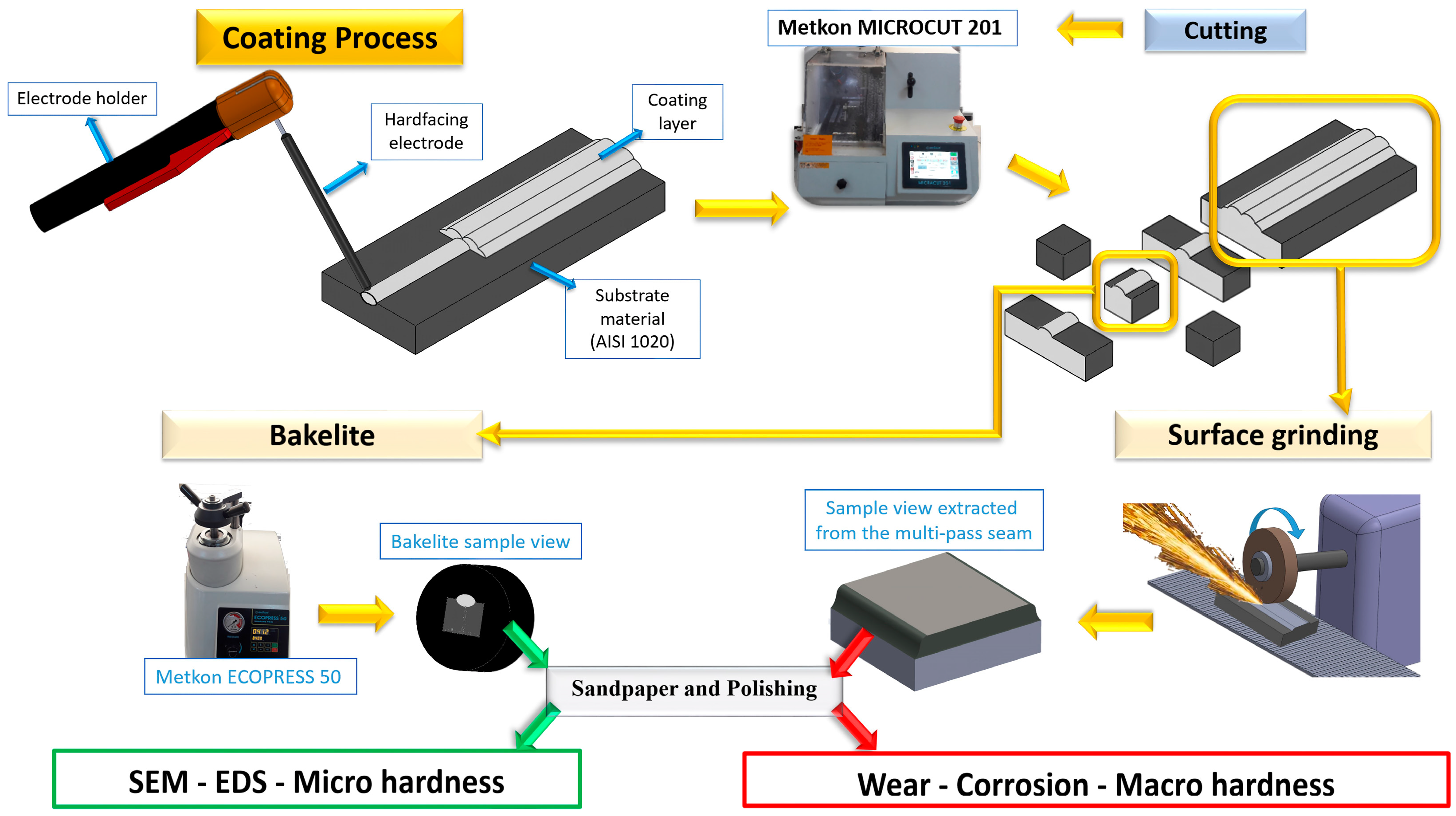
2. Experimental Procedure

In the experimental studies, hardfacing electrodes containing different ratios of Fe-Mo-B were produced. In the production of hardfacing electrodes, a H08A low carbon steel wire rod was used as the core metal, and ferromolybdenum, ferroboron, flux material (5%), and binder potassium silicate (17.5%) were used in the cover composition. The chemical compositions of ferro alloy powders and core metal are given in Table 1.
Covered electrodes were weighed by calculating their atomic ratios according to the compositions given in Table 2, and the powders were first mixed wet by adding a binder and then mixed as dry. The covering paste in the viscose form was pressed in a PTFE-coated aluminum mold and the core metal was passed through it. Atomic calculation of the electrode compositions and details of the production process can be found in previous studies carried by Kocaman et al. [32,33]. The coating process was carried out using an electric arc welding machine at a 125 A (amperes) and 25 V (volts) constant potential on the AISI 1020 steel substrate, of which its chemical composition is given in Table 1.
The coated samples were cut and subjected to standard metallographic operations as can be seen in Figure 1. Firstly, the samples’ surfaces were sanded with 240, 320, 600, 800, 1200, and 2500 mesh SiC paper, respectively. Then, the samples were polished with 6, 1, and 0.05 µm Al2O3 paste, respectively. The samples to be used for microstructural examinations were etched using 4% Nital solution. The surface morphology and elemental distribution of the samples were analyzed using the JEOL-JSM-6060 scanning electron microscope (SEM) and X-ray spectroscopy (EDS) device coupled to the scanning electron microscope. The phases in the microstructure were analyzed with Rigaku brand X-ray diffraction analysis (XRD) and defined using the X-pert High score program.
Hardness measurements of hardfacing coatings were carried out with Bulut Makina DIGIROCK RB model hardness device with Hardness Rockwell A Scale (HRA) and Hardness Rockwell C Scale (HRC). Rockwell hardness measurements were carried out using a conical diamond indenter under a load of 60 kgf for HRA and 150 kgf for HRC. Shimadzu HMV-G21D Hardness Vickers (HV) microhardness device was used for microhardness measurements. A dry sliding wear test was performed using a TriboTechnic wear device with reciprocating wear mode against an Al2O3 (2050 HV) ball with 10 mm dimensions. The average surface roughness of wear samples was measured as Ra = 0.035 (±0.003) µm before the wear test. Wear tests were carried out at two different loads, 4 N and 8 N, and at two different wear distances, 400 m and 800 m. Following the wear tests, the area of wear tracks was measured using a Taylor Hobson 2D profilometer. All wear tests were performed at a constant humidity (31%–34%) and room temperature (23–25 °C). Friction coefficient (FC) data were provided via a computer software connected to the wear device and was calculated according to the following formula.
F C = F s F N
In the formula, FS represents the lateral load (N) and FN the normal load.
The wear rate was calculated according to the formula [34] below, using the data obtained from the wear tracks’ measurement.
W R = V / S
where V is the wear trace volume and S is the sliding distance.
The wear track was calculated with Equation (3).
V = A E
where A is the cross-sectional surface area of the wear track and E is the eccenter distance which was chosen during all tests as 10 mm.
The Gamry 1010 E potansiyotat electrochemical work station equipped with a classic three-electrode system was used during electrochemical tests. A saturated calomel electrode (SCE)’s reference electrode and graphite counter electrode was used in the corrosion tests. Open circuit potential (OCP) was measured during 1200 s. The tests were performed in a 0.5 M NaCl solution with a potential range of −0.5 V, +1.5 V and the scanning rate was chosen as 1 mV/s. Ecor (corrosion potential) and Icor (corrosion current) were calculated by using Gamry Echem software (https://www.gamry.com/). Electrochemical impedance spectroscopy (EIS) tests were performed with an alternative current signal of 10 mV in the range of 100 kHz to 10 mHz.

3. Results and Discussion

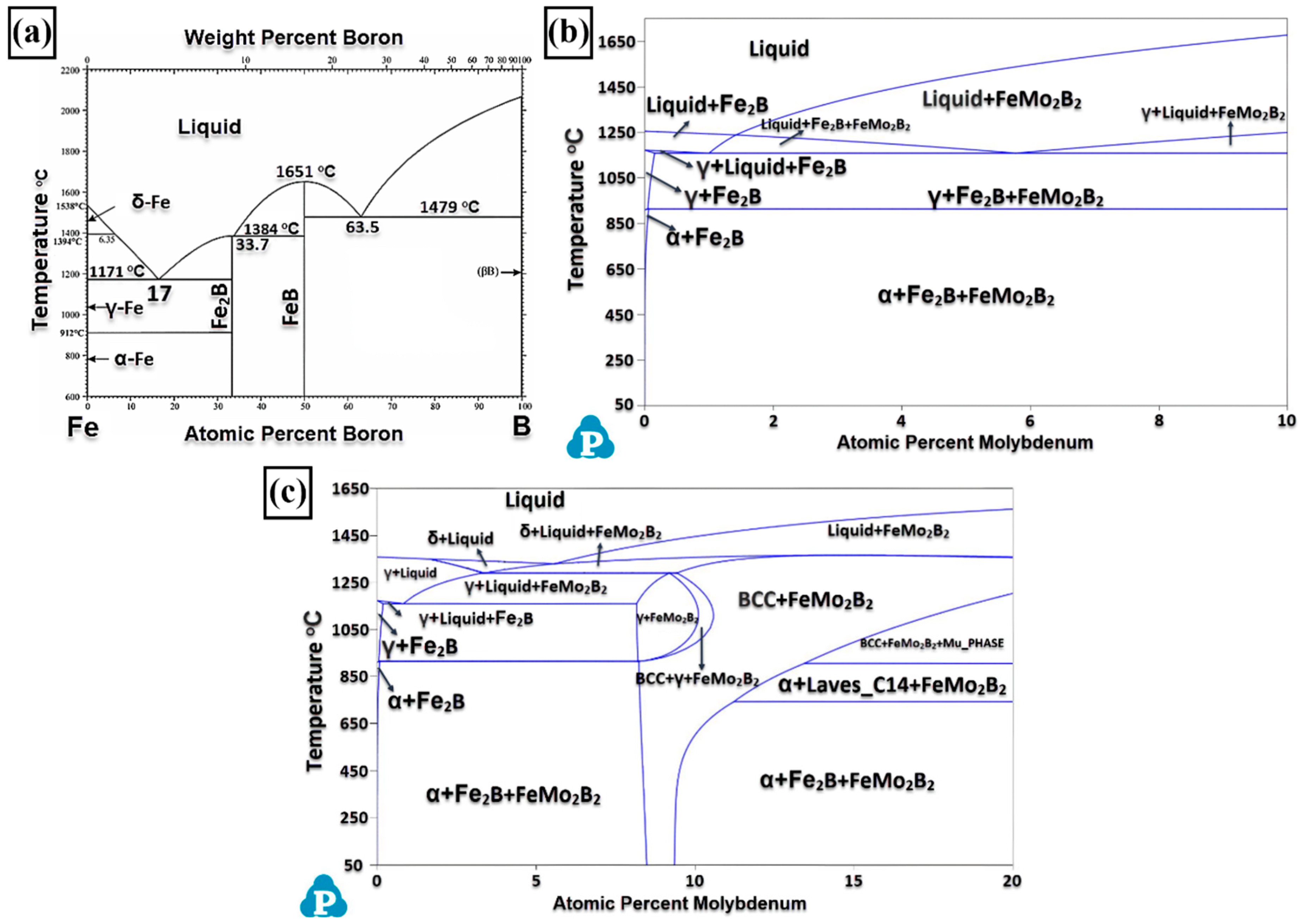
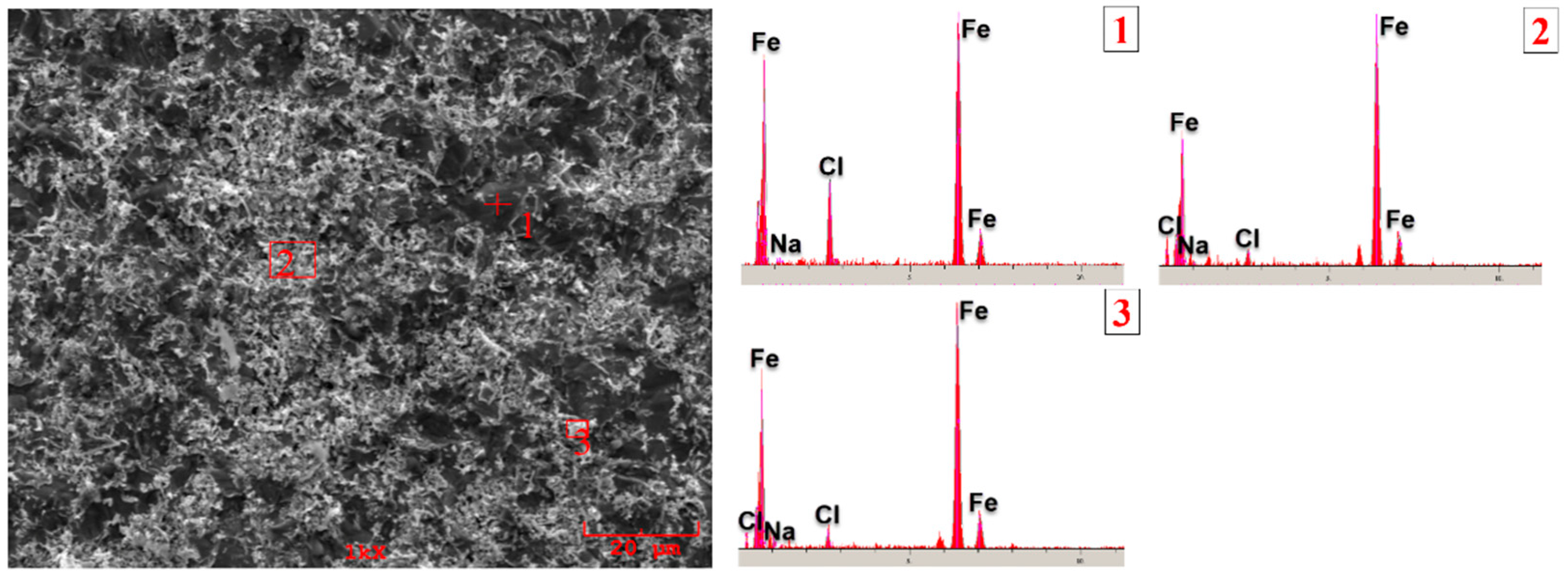
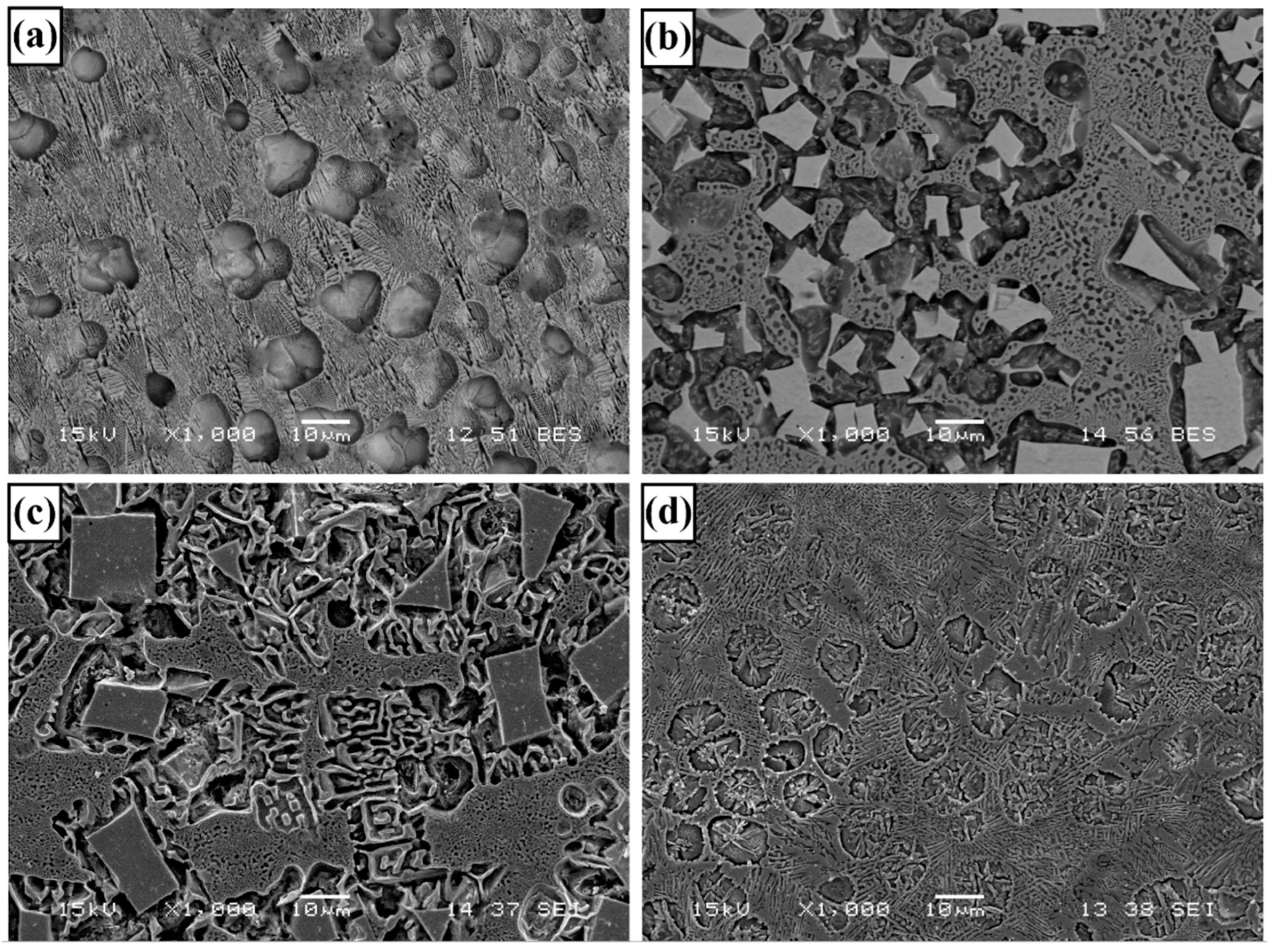
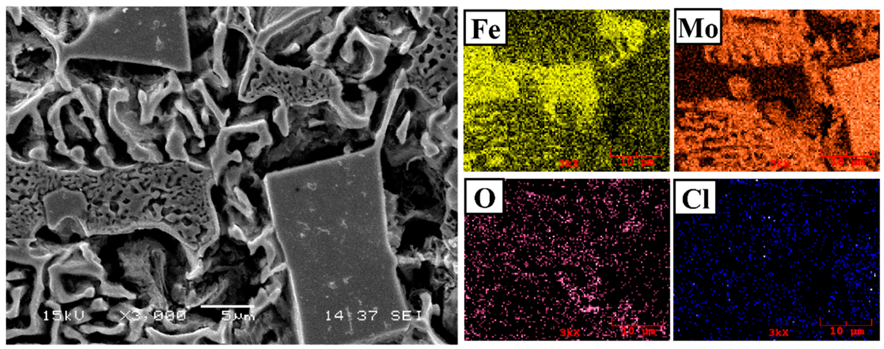
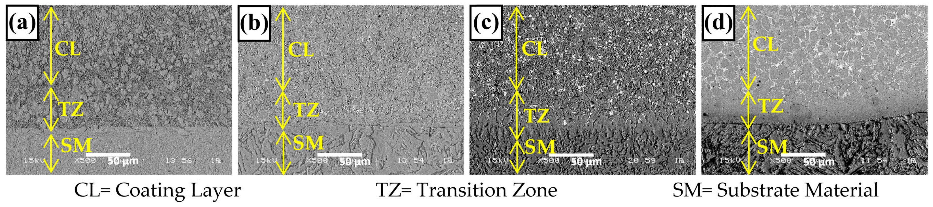
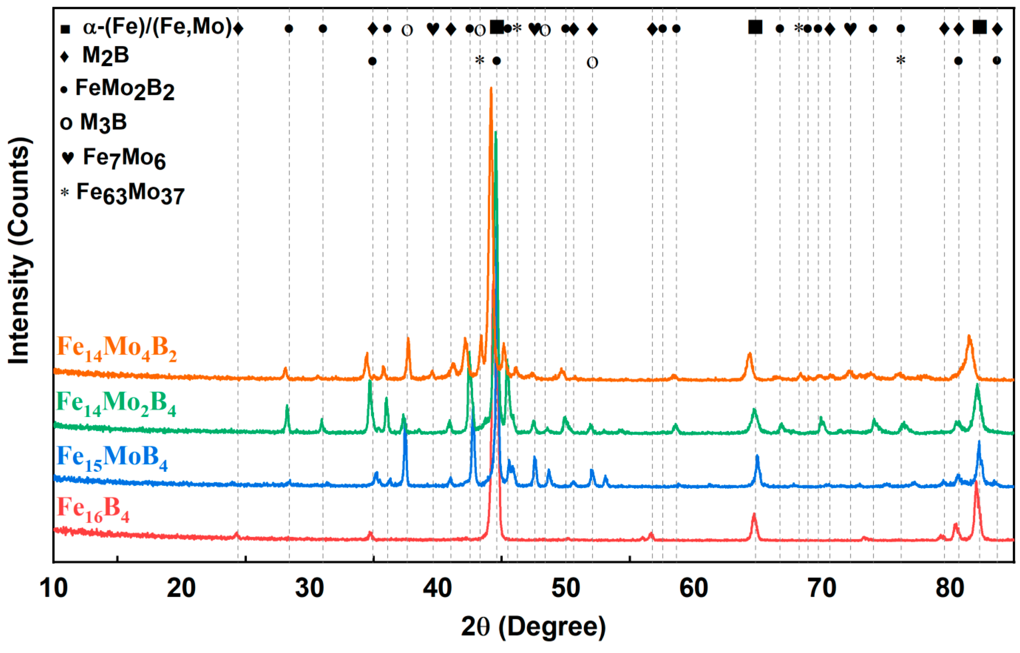
3.1. Microstructure and Phases Analysis

Figure 2 shows the substrate–coating transition zone of hardfacing coatings. One of the most important features that distinguish hard coating from other coating methods is that their coating thickness is quite high and they create strong metallurgical bonds with the substrate. These features enable hardfacing coatings to be used for a long time in aggressive environments. On the other hand, porosities that will occur in the transition zone and coating layer after coating will significantly reduce the performance of the coating. SEM images show that the alloys selected as the coating material and the process are compatible and a metallurgical bond is formed between the substrate material and the coating layer. In this study, the average thickness of coatings was measured as 5–5.5 mm. Additionally, no significant porosity formation was observed in either the transition zone or the coating layer. In the SEM images, during the coating process carried out at room temperature, columnar grains were formed at the interface, extending from the substrate material towards the coating area. During repeated melting and solidification, the temperature increases and the columnar grains grow from the colder substrate material towards the coating region. The interface, which develops depending on the dynamic solidification conditions of the welding process, has been reported in similar studies [25,32].
XRD analysis of hardfacing coatings is given in Figure 3. According to XRD analysis, the changing alloying element in the coating composition was affected by the phases in the microstructure. In the XRD analysis, α-Fe, FeMo2B2, M2B-type boride, R-Fe63Mo37, and trace amounts of the Fe3B and µ-Fe7Mo6-phase were detected. Normally, the R-Fe63Mo37 and Fe3B phase is a non-equilibrium phase formed under rapid cooling conditions [35]. However, it can be seen in trace amounts in a solidified microstructure under dynamic solidification conditions such as the welding process.
SEM images of hardfacing coatings are given in Figure 4. The Fe16B4-based hardfacing coating composition contains 20% atomic boron. During solidification, the Fe2B phase is expected to solidify first as seen in the Fe-B phase diagram given in Figure 5. As the eutectic temperature drops below the eutectic temperature, which is approximately ~1177 °C, the liquid phase will solidify eutectically. For this reason, primary Fe2B phases and the eutectic α-Fe + Fe2B structure can be found in the coating microstructure. However, since the electrode composition passes very close to the eutectic point, the amount of primary phases is expected to be low. In EDS analysis, α-Fe (point 1) represents Fe2B with a partial block structure (point 2) and a α-Fe + Fe2B eutectic structure (point 3). Normally, the boron element cannot be detected quantitatively via EDS analysis. However, with EDS analysis, signals can be received from points containing boron. As expected, there were trace amounts of block-structured Fe2B phases that solidify primarily, and the microstructure largely solidifies as a eutectic structure.
It is seen that significant changes occur in the microstructure of the Fe15MoB4-based coating with the addition of molybdenum in the electrode cover composition. According to EDS and MAP analysis, a molybdenum signal is received from these block-structured phases. It is also understood that these block-structured phases contain boron. It is known that for a fixed boron ratio in the Fe-Mo-B system, increasing the amount of molybdenum shifts the solidification to the hyper-eutectic side [36]. On the other hand, the high melting temperature and thermodynamically stable phase in the Fe15MoB4-based coating is the FeMo2B2 compound [37,38]. For this reason, solidification begins with the formation of FeMo2B2 solid crystals and this phase grows with a block structure. After the formation of the FeMo2B2 phase, theoretically, molybdenum is consumed in the melt, but there is still 15% atomic boron. Solidification continues with the formation of α-Fe, similar to a sub-eutectic composition according to the Fe-B phase diagram. For this reason, there are α-Fe islands around the FeMo2B2 phase. When the temperature drops below the eutectic line, the remaining liquid solidified as a α-Fe + Fe2B eutectic structure and continued to grow. It indicates that the phase detected as M2B in the XRD analysis is taken from the α-Fe + M2B structure, which solidifies eutectically around the block-structured phases. Although it was assumed that this system solidifies according to the Fe-B phase diagram, the eutectic formed is morphologically different from the eutectic structure formed in the Fe16B4-based coating. It is known that molybdenum can be dissolved in the Fe2B phase [39]. Possibly, molybdenum dissolved in the Fe2B phase causes this phase to solidify as (Fe,Mo)2B and the morphology of the eutectic structure changes. A similar microstructure has been reported as a reticular eutectic structure in the literature [36]. Also, a molybdenum signal was received from EDS region number 2. Although the solubility of molybdenum in α-Fe is quite low under normal conditions, its solubility has been reported to be ~24% at ~1450 °C [40,41]. In a process where solidification is dynamic, such as welding, rapid regional or structural cooling might have occurred [33]. For this reason, it was normal for the molybdenum solubility to increase regionally in α-Fe, and the dark gray regions are called α-(Fe,Mo). As a result, block-structured FeMo2B2, α-(Fe,Mo), and α-Fe + (Fe,Mo)2B eutectics were expected to form in the final microstructure.
There is a significant increase in the ratio of block-structured FeMo2B2 phases in the SEM image of the Fe15MoB4-based coating given in Figure 4. The thermodynamic analysis performed with PANDAT software (https://computherm.com/) (Figure 5) show similar phases occurring in the Fe15MoB4- and Fe14Mo2B4-based coatings. In XRD analysis, it was determined that the Fe14Mo2B4-based hardfacing coating contained α-Fe, FeMo2B2 phase, M2B-type boride, and trace amounts of Fe3B borides in its microstructure. Solidification is expected to begin with the formation of the FeMo2B2 phase, similar to the Fe15MoB4-based coating. However, in the microstructure of the Fe14Mo2B4-based coating, it is seen that the block-structured phases and the eutectic structure change morphologically. It also has been reported in the literature that the FeMo2B2 phase formed in the Fe-Mo-B system can solidify in different forms and the morphology of this phase can change depending on the Mo/B ratio [38]. In similar studies, it has been reported that a eutectic structure consisting of a FeMo2B2 and Fe,Mo solid solution can be found around the FeMo2B2 phase [39]. However, this eutectic structure solidifies into a morphologically floriform structure. Another phase detected in the XRD analysis, the M2B type phase, indicates the eutectic-solidified Fe2B phase. As stated in previous studies, Fe2B can dissolve some molybdenum during solidification and form the (Fe,Mo)2B phase [39]. The Fe3B phase detected in trace amounts in the XRD analysis was not visible in the microstructure in a distinguishable way. Yin et al. [36] stated that the Fe3B phase was distributed within the Fe-M2B eutectic structure. In the final microstructure, which consists of FeMo2B2, α-(Fe/Mo) + FeMo2B2 eutectic (floriform structure that solidifies around FeMo2B2), α-(Fe/Mo), and α-(Fe/Mo) + (Fe,Mo)2B (reticular eutectic structure).
A structure consisting of light-colored phases, eutectic-like structures with the same contrast as these phases, and a matrix phase can be seen in the SEM image of the Fe14Mo4B2-based coating. According to the thermodynamic analysis performed with PANDAT software (https://computherm.com/), the α-Fe, FeMo2B2, and Fe2B phases were expected to be present in the microstructure under stable solidification conditions. However, in XRD analysis, in addition to the α-Fe and FeMo2B2 phases, µ-Fe7Mo6 and R-Fe63Mo37 phases were detected. According to the Fe-Mo phase diagram, the R-Fe63Mo37 phase is an unstable phase below 1200 °C and indicates solidification at a high cooling rate [25]. A molybdenum signal was detected from white island-shaped phases in the EDS analysis. The first phase expected to form under balanced conditions was the FeMo2B2 phase. However, the surface of the island-shaped phase shown at EDS point number 1 has a faceted structure, unlike the FeMo2B2 phase. Possibly, this phase is the R-Fe63Mo37 phase, which solidifies out of equilibrium, as stated in the literature [25]. The µ-Fe7Mo6 phase, which was detected in trace amounts in the XRD analysis, could not be clearly detected in the microstructure. Previous studies also show that this phase is not clearly distinguishable [25,42]. Eutectic regions indicate the FeMo2B2 phase detected in XRD analysis. The amount of molybdenum affects not only the morphological properties of FeMo2B2 phases, but also the morphology of the eutectic structure (α-(Fe,Mo) + FeMo2B2). For this reason, increasing the amount of molybdenum and decreasing the boron rate affects the distance between the lamellar in the eutectic structure in the Fe14Mo4B2-based coating.

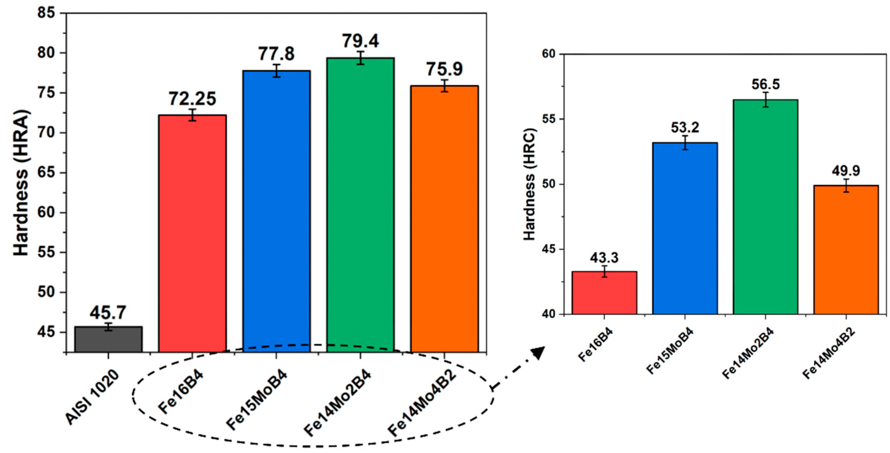
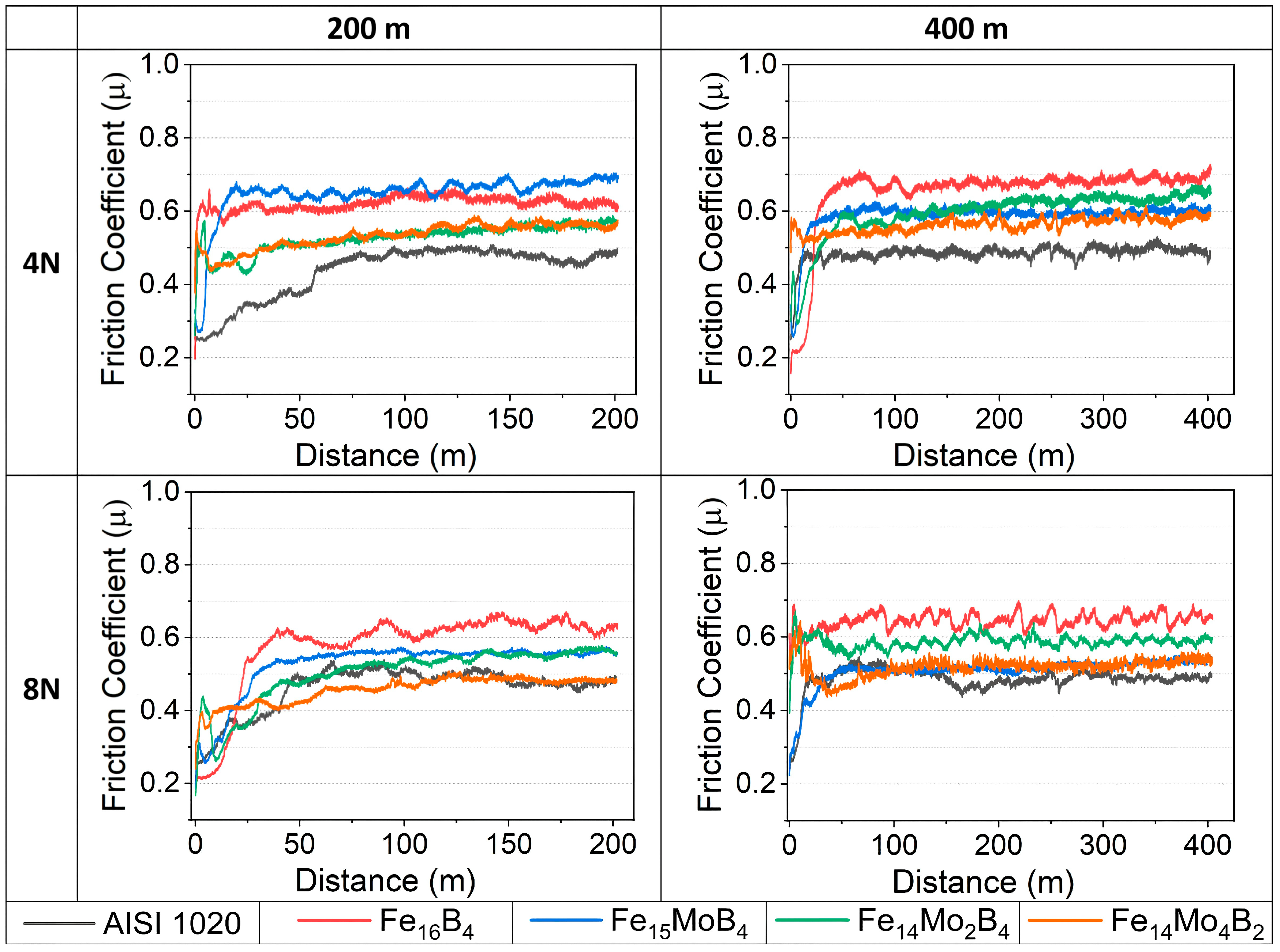
3.2. Hardness and Wear Tests

Figure 6 shows the hardness test results of hardfacing coatings. In the Fe16B4-, Fe15MoB2-, Fe14Mo2B2-, Fe14Mo4B2-based coatings carried out on the AISI 1020 steel substrate, there was an increase of 58%, 70%, 73%, and 66% according to the substrate material, respectively. Additionally, it was observed that an increase in hardness as the amount of molybdenum added to the Fe-B-based hardfacing electrode composition increases. With 5% molybdenum added to the electrode cover composition, an increase in hardness of 22.8% was observed, and with the addition of 10% molybdenum, an increase in HRC hardness of 30.48% was observed compared to the Fe16B4-based coating. On the other hand, the hardness value of the Fe14Mo2B4-based hardfacing coating was measured as 56.5 HRC, while the hardness value of the Fe14Mo4B2-based hardfacing coating was measured as 49.9 HRC. In other words, the hardness value of Fe14Mo2B4-based hardfacing was approximately ~13% higher than that of Fe14Mo4B2-based hardfacing. This shows that although the hardness increases with molybdenum for Fe-Mo-B-based coatings, the amount of boron in the coating composition has a significant effect on the increase in hardness. In addition, the top values of hardness were related to the phases in the microstructure, and especially the FeMo2B2 phase plays an important role in increasing the hardness.
In the study, the lowest microhardness value was measured from the substrate material as seen in Table 3. Among the coated samples, the lowest matrix phase hardness was measured in the Fe16B4-based hardfacing coating. The matrix phase hardness of the Fe16B4-based coating gives almost the same results as the substrate material. The solubility of boron, an interstitial element, in the α-Fe matrix was quite low. For this reason, the boron in the composition was found in Fe2B or the eutectic phase formed by this phase. With the addition of atomic 5% molybdenum into the alloy, there was a significant increase in the hardness of the matrix phase. Additionally, it was observed that this increase was not only in the matrix phase, but also in the eutectic structure. Due to the nature of the welding process, molybdenum may dissolve to some extent in the matrix phase and the Fe2B phase. This situation causes an increase in hardness in the matrix phase as a result of solid solution hardening [43]. Similarly, molybdenum dissolved in the Fe2B phase causes the hardness of this phase to increase. Although the hardness of the other phases was similar, trace changes were observed depending on the composition, especially in the matrix phase. On the other hand, the matrix hardness of the Fe14Mo4B2-based coating was less than that of other coatings containing molybdenum. The hardness of the R-Fe63Mo37 phase in the microstructure of the same coating was also measured to be lower than the boron-containing phases. As can be seen from previous studies, changes in both microstructural and atomic dimensions change the hardness of the coating [44,45]. The difference in the matrix phase between the compositions might cause distortion in the lattice, causing the hardness to be slightly different. Microstructurally, each phase prevents dislocation movement, but the physical properties of the phase determine the limit values of plastic deformation. As stated in the literature, boron-containing phases play a decisive role on the hardness of the coating [19]. The hardness values measured from the phases in the microstructure have an effect on the hardness. Although the hardness values measured in the study depend on the composition and production method for Fe-Mo-B-based alloys, they appear to be compatible with various studies [46,47,48].
Figure 7 shows the wear rate graph of hardfacing coatings depending on load and distance. According to the graph, it is understood that the wear rate increases with both the increasing distance and increasing load. In the study, the highest wear rate was measured from the substrate material. Among the coated samples, the highest wear rate was measured in Fe16B4 and the lowest wear rate in the Fe14Mo2B4-based coating. Wear rates exhibit a similar behavior to the hardness results. As Archard stated [49], the wear rate varies inversely with the hardness. The basic philosophy of hardfacing coatings is to cover the surface with a harder layer than the substrate material. As mentioned above, each hard phase in the microstructure of this hard layer formed on the substrate surface changes the effect of the coating on wear. In addition, not only the hardness of these phases, but also their compatibility with the surface, morphology, etc., properties also affect the wear behavior of the coating. In this study, the hard eutectic α-Fe + Fe2B structure, which forms the microstructure of the Fe16B4-based coating, increases the wear resistance of the substrate material. The high-hardness FeMo2B2 phase formed in the microstructure with the addition of molybdenum and the different morphologies of this phase cause further increase in wear resistance. On the other hand, although the wear resistance increases with the increasing molybdenum amount, the wear resistance of the Fe14Mo2B4-based coating was measured to be higher at all loads and distances than the wear resistance of the Fe14Mo4B2-based coating. Boron is a critical element in the formation of hard phases, and the volumetric fraction of the phases formed by boron affects the wear resistance of the coating. In addition, although boron provides the formation of the hard phase, the matrix phase is critical in terms of both hardness and wear resistance. The fact that molybdenum is soluble in the matrix phase and increases its hardness resultingly has an effect on wear. Likewise, both the hardness and wear resistance of the Fe16B4-based coating, where the matrix phase is soft, were measured to be lower than the Fe14Mo4B2-based coating.
Figure 8 shows the friction coefficient graphs obtained after the wear test at different loads and distances applied to hardfacing coatings. Friction coefficient values vary between ~0.4 and 0.7 µ. According to the friction coefficient data of the coated samples, it can be said that the highest friction coefficient value was obtained in Fe16B4-based hardfacing and the lowest friction coefficient values were obtained in Fe14Mo4B2-based hardfacing. The overall friction coefficient is closely related to the surface profile and phases in the microstructure [50,51,52]. In composite materials such as hardfacing, each phase has a different effect on wear. On the other hand, the hardness, morphology, volumetric ratio, and distribution of these phases are other parameters that affect the friction coefficient. The friction coefficients given in Figure 8 act independently of the surface hardness. However, it can be said that the smoothest surface among the samples is on the Fe14Mo4B2-based hardfacing coating after the substrate material. On the other hand, the composite structure seen in the microstructures of other coatings is likely to create resistance during sliding. These composite structures might cause an increase in the coefficient of friction. Similar studies in the literature have stated that the coefficient of friction increases with the increase in the amount of hard phase in the metal matrix composite [53]. In the study, no correlation was found in the change in friction coefficients according to load and distance.
In the EDS analysis of the substrate material shown in Figure 9, an intense amount of oxygen signal was received from the dark areas. The formation of an FeO-based oxide layer during wear on the carbon steel surface has been reported in similar studies [54]. The microstructure of the substrate material did not contain factors such as grain boundaries, secondary phases, and eutectic structure that would create resistance during wear compared to the coated samples. For this reason, friction occurs on a smoother surface. In the friction coefficient graph given in Figure 8, it reached the steady-state wear phase after a short running-in period. The homogeneous oxide layer formed on the surface might acted as a solid lubricant, causing the friction coefficient to be relatively lower than other samples. It is seen that this oxide layer forms debris at some points. Local adhesions may occur as a result of micro weld in softer and easily oxidized substrate material. Increasing heat during friction and the change in surface topography due to the oxide layer formed may also cause fluctuations in the friction coefficient [55]. On the other hand, oxide-based debris formed as a result of the delamination of the oxide layer was seen in the SEM image of the substrate material. It was understood that wear was dominated by oxidative and adhesive wear mechanism. The worn surface appearance of the hardfacing-coated samples shown in Figure 9 shows that the oxidized parts remained more localized compared to the substrate material.
As a result of the SEM analysis performed on the coated samples, different mechanisms played an active role during wear. It can be seen that debris and delaminations were formed on the surface of the Fe16B4-based hardfacing coating shown in Figure 10a after wear. Debris might have occurred due to the sawing effect created by the eutectic phase during friction. It was also observed that delamination occurs in the soft (matrix) phase during friction in the eutectic structure. This indicates that it might be pulled out due to adhesion formed in the soft matrix phase with the increasing heat in the later stages of friction. With the addition of molybdenum, the delamination of hard phases formed in the microstructure decreased by reducing the oxide detachment on the surface. However, the abrasive wear increases with the increasing hard phase friction and micro-abrasive lines appear on the surface. One of the basic mechanisms expected to develop during the wear of hardfacing coatings is micro-abrasive wear, which was expected to occur due to a three-body wear mechanism. As a result of the micro-abrasive wear mechanism, small pieces pulled out from the friction surfaces were plastered on the surface, causing wear called smeared [56,57,58]. The SEM image and MAP analysis shown in Figure 9 indicate this situation, where cracks occur directly in oxidized areas. Similarly, the cracks formed in Figure 10b and c indicate removal from the surface after smearing. On the other hand, block-structured phases formed via the addition of molybdenum caused a large hardness difference between the matrix and the particle. The difference in hardness between the matrix and the hard phase might have caused fatigue in the matrix phase. Fatigue occurring during wear might cause fatigue cracks and subsequent ruptures after a while, as shown in the SEM image of the Fe15MoB2-based coating given in Figure 9b. As a result, hard phases such as M2B and FeMo2B2 play an active role during friction. These hard phases and eutectic structures were in direct contact with the abrasive. For this reason, the increasing amount of block-structured or eutectic hard phase acts in the direction of the increasing wear resistance. Similar results have been reported in previous studies [27]. In the study, it was determined that micro-abrasive, adhesive, and oxidative wear were the dominant wear mechanism.

3.3. Corrosion Behavior

OCP curves are given in Figure 11a. The OCP curves become stable in a short time. As stated in the literature, when the open circuit potential reaches equilibrium, it indicates that the film formation and dissolution on the surface are in balance [59]. In all OCP curves, there was first a slight movement towards the anodic side and then the curves became stable. The OCP value of the substrate material was measured to be slightly more positive than the coated samples. This might be due to the oxide layer that forms more easily on the surface of the substrate material. According to the OCP test, the anodic corrosion tendency decreased with the increasing molybdenum amount in the coating composition. The OCP value of the Fe16B4-based coating was measured to be similar to molybdenum-containing coatings.
Tafel curves obtained from the samples subjected to the electrochemical corrosion test in the 0.5 M NaCl solution are given in Figure 11b. The corrosion potential obtained from these curves gives information about the direction of corrosion [27,60]. According to the curves, there was no big difference in corrosion potentials. However, the most noble sample in terms of corrosion potential is the AISI 1020 steel substrate. This shows the sample substrate material with the lowest corrosion tendency according to its corrosion potential. According to the corrosion parameters given in Table 4, it is seen that the addition of molybdenum to the molybdenum Fe-B-based coating composition does not cause a linear change on the corrosion potential. Among the coated samples, the noblest corrosion potential was measured in the Fe14Mo4B2-based coating. On the other hand, current density, which is a critical parameter in the kinetic interpretation of corrosion, is directly related to the rate of corrosion. According to corrosion current density values, the lowest current density was measured in the Fe16B4-based coating. Many researchers have reported that Fe-B alloys near the eutectic point have very good corrosion resistance [61,62,63,64]. There was a decrease in the current density values with the addition of molybdenum into the Fe16B4-based coating. In other words, the corrosion resistance of the coating has increased.
Another method used to understand corrosion in kinetic terms is the EIS method. The similarity of the EIS curves seen in Figure 11c indicates that similar corrosion mechanisms have developed in the coating layers. On the other hand, the diameter of the capacitive loop varies in direct proportion to the corrosion resistance. The corrosion resistance of the coating with a large capacitive loop diameter is high [65,66]. EIS test parameters obtained by equivalent circuit modeling are given in Table 5. According to the model, Rs is a measure of the solution resistance and Rct is a measure of the polarization resistance. A higher Rct value indicates higher corrosion resistance. The fact that both the capacitive loop diameter and the Rct value are large indicates that the corrosion resistance of the Fe16B4-based coating is higher. This can be associated with the microstructure of the Fe16B4-based coating. Factors such as phases and grain boundaries within the microstructure increase the polarization resistance [67]. Rct resistance increases especially in Fe16B4-based coatings that contain a high fraction of eutectic structure. According to the EIS data, the AISI 1020 steel substrate, which does not contain grain boundaries in the microstructure, has low corrosion resistance. Although the microstructure of the Fe14Mo2B4-based coating is complex, the Rct value was low. This may be related to the morphology and composition of the eutectic structure.
In the post-corrosion SEM image of the substrate material shown in Figure 12, it is seen that a cotton-like layer is covering the surface. In the EDS analysis carried out in this region, intense signals belonging to Fe and Cl elements were received. This indicates that the iron on the surface is dissolved as a result of the anodic reaction and ferrous salts are formed on the surface.
The reaction of the anodic dissolution occurring on the substrate surface is the oxidation reaction of α-Fe and is expected to occur according to the reaction given below. In the SEM image, it is understood that this reaction develops homogeneously on the surface. This type of homogeneous corrosion is a less dangerous corrosion mechanism, and generally, the homogeneous oxide layer formed on the surface polarizes the surface. However, the breakdown of this layer accelerates corrosion.
Anodic reaction [68,69]:
Fe Fe+2 + 2e
Cathodic Reaction:
½O2 + H2O + 2e  2OH
direct oxygen reduction of the cathodic reaction
2Fe + 2H2O +O2  2Fe+2 + 4OH 2Fe(OH)2
Figure 13 shows SEM images of hardfacing coatings after corrosion. In the images, there was no corrosion damage in the parts formed by FeMo2B2, R-Fe63Mo37 and these phases within this eutectic, but there was a significant amount of dissolution in the α-Fe/(Fe,Mo) regions between the matrix phase and the eutectic phase. This situation indicates the formation of galvanic corrosion caused by the potential difference between the boride phase and α-Fe. Also, this results in selective corrosion of the matrix phase.
In the Fe16B4-based coating, the matrix phase consists of α-Fe and dissolution can occur according to the reactions given above. The molybdenum added to the Fe16B4-based coating might have increased the corrosion resistance of the matrix by dissolving it in the matrix phase. Similarly, there was a significant dissolution in the phases around the FeMo2B2 phase. As a result of the potential difference between the FeMo2B2 phase and the surrounding phases, it may have an accelerating effect on dissolution. Similarly, it has been reported in the literature that the low molybdenum-containing phase in the region adjacent to the high molybdenum-containing phase in the eutectic structure will have corroded preferentially and caused intergranular corrosion [70]. It was also clearly seen in the SEM images. In the SEM image and MAP analysis given in Figure 14, the iron signal received from the eutectic region shows that there was no dissolution in these regions. That is, both M2B and FeMo2B2 phases behave as noble, with respect to the matrix phase.

4. Conclusions

In this study, it was aimed to investigate the effect of molybdenum on an Fe-B-based hardfacing coating. For this purpose, Fe-Mo-B-based hardfacing electrodes with different compositions were produced. These produced electrodes were observed microstructurally and hardness, wear, and corrosion tests were performed. Additionally, the results were compared with an AISI 1020 steel substrate and Fe-B-based hardfacing. The findings obtained in the study are as follows;
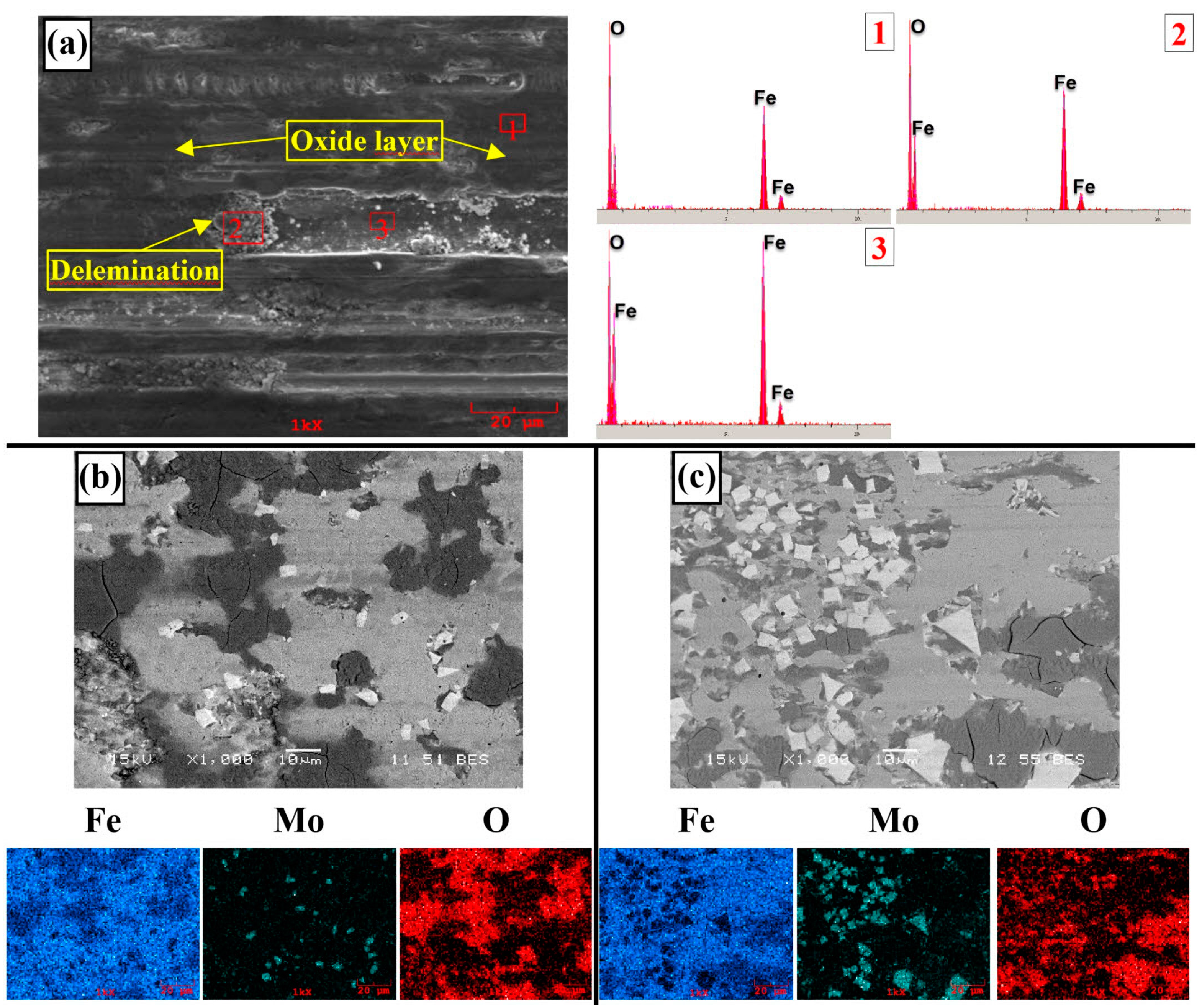
  • It has been determined that changes made in the electrode cover composition change the phases in the microstructure and that even trace changes have a significant morphological effect on some phases. In the study, α-Fe, FeMo2B2, Fe2B, and R-Fe63Mo37 phases were detected as major phases, and Fe3B and Fe7Mo6 phases were detected as minor phases. It has also been determined that molybdenum can dissolve in the α-Fe and Fe2B phase and can affect the morphological and mechanical properties of both these phases and the eutectic structures formed by these phases.
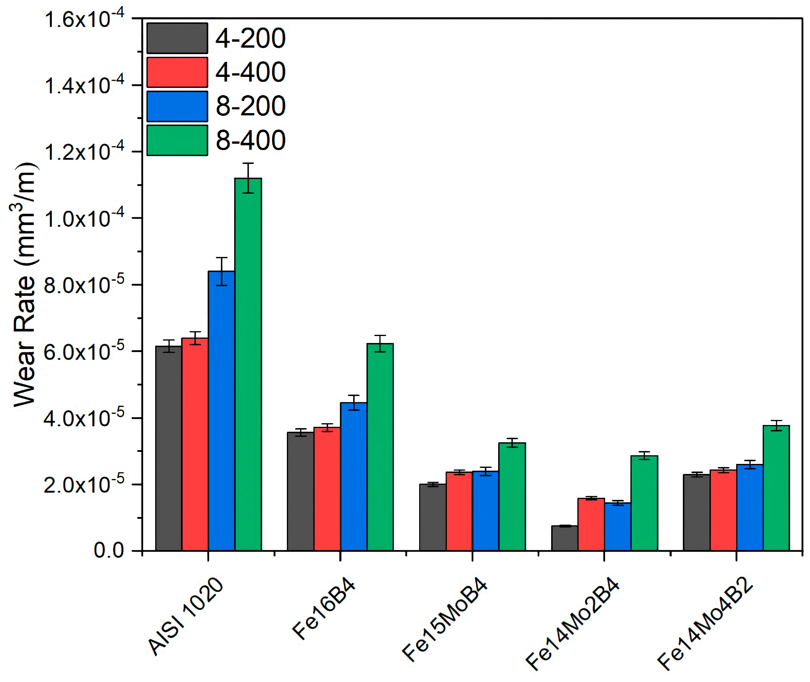
  • Neither molybdenum nor boron could provide the effect of both on the hardness and wear resistance of the coating. In addition, this effect reaches its maximum level for mixtures made in certain proportions. For this reason, optimizing the compositions in hardfacing coating works was critical. In the study, the highest hardness value was obtained in the Fe14Mo2B4-based coating as 56.4 HRC. It was observed that the hardness of this coating was ~73% higher than the substrate material and ~30.5% higher than the Fe16B4-based coating. According to microhardness measurements, although the hardness of the phases in the microstructure varies over a wide range, the highest phase hardness was measured as 3228 HV in the FeMo2B2 phase. In the study, the highest wear resistance was obtained in the Fe14Mo2B4-based coating. According to the wear rate values, up to ~8.1 times higher wear resistance was obtained in the Fe14Mo2B4-based coating compared to the AISI 1020 substrate material and up to ~4.7 times higher than the Fe16B4-based coating.
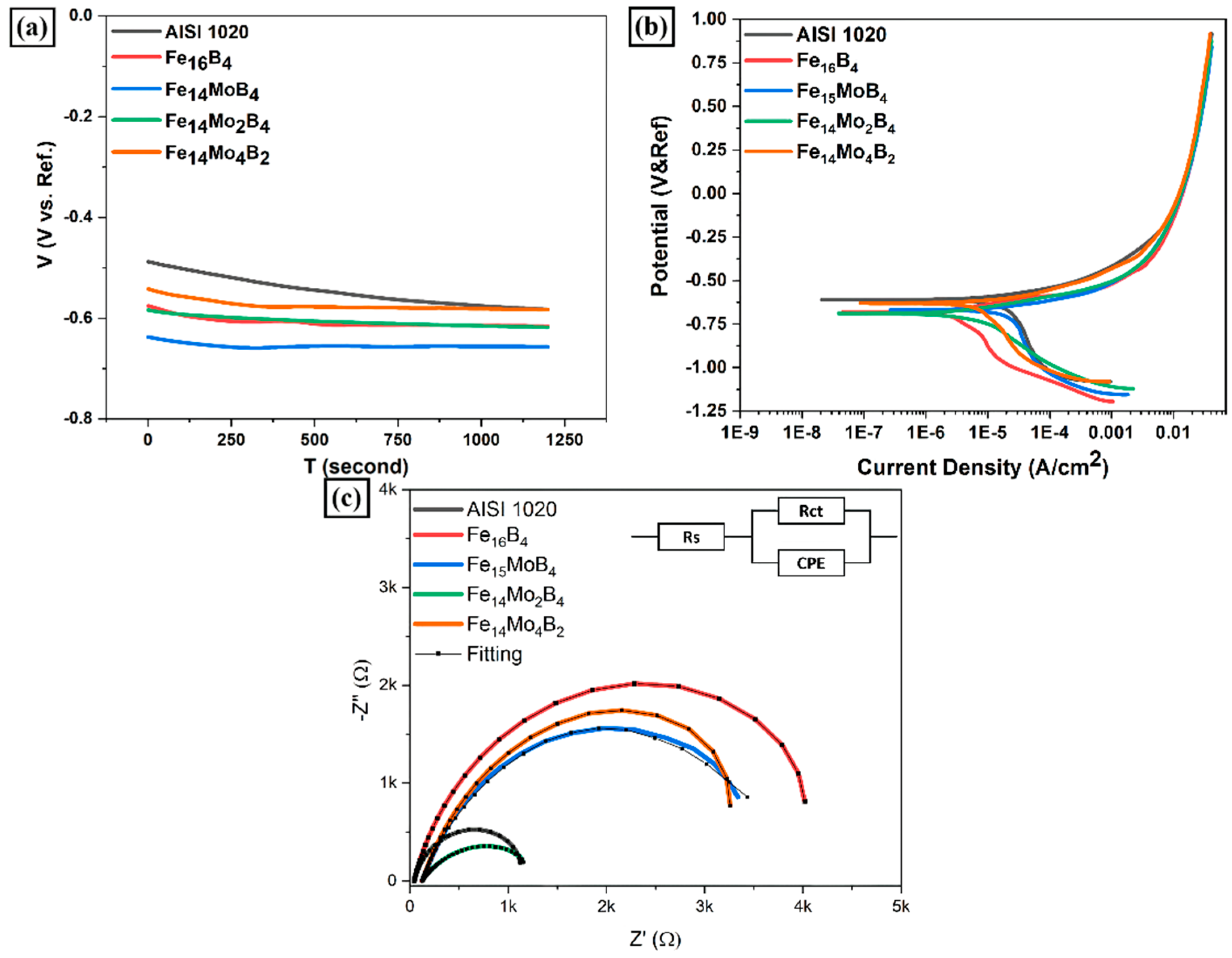
  • According to the corrosion test results, it was observed that there was no significant difference between the corrosion potentials of the substrate material and the coated samples. However, a significant difference was detected between the corrosion current density values. The current density of all samples with hardfacing coating is lower than the base material, meaning their corrosion resistance was better. In the study, the lowest current density value was measured as 2.078 µA/cm2 in the Fe16B4-based coating and it was found to be ~13.6 times more resistant to corrosion than the substrate material. Although the corrosion resistance of the Fe16B4-based coating, that is, molybdenum-free, was high, it has been determined that the corrosion resistance increases with the increasing molybdenum amount in molybdenum-containing hardfacing coatings.
  • From this study, it can be concluded that molybdenum is a good alternative that can be added to Fe-B-based hardfacing alloys to improve the properties of the coating. Furthermore, extending this study to reveal the effect of high temperature wear behavior on the coating will be beneficial for potential applications.

Funding

The study has been supported by the Scientific and Technological Research Council of Türkiye (TÜBİTAK) project number 219M195.

Institutional Review Board Statement

Not applicable.

Informed Consent Statement

Not applicable.

Data Availability Statement

The data cannot be made publicly available upon publication because there is no suitable repository that exists for hosting data in this field of study. The data that support the findings of this study are available upon reasonable request from the authors.

Acknowledgments

The author would like to thank Zonguldak Bulent Ecevit University and Sakarya University, whose laboratory facilities were used to carry out the study.

Conflicts of Interest

The author declares no conflict of interest.

References

  1. Zhang, K.; Zheng, Z.; Zhang, L.; Liu, Y.; Chen, S. Method for Dynamic Prediction of Oxygen Demand in Steelmaking Process Based on BOF Technology. Processes 2023, 11, 2404. [Google Scholar] [CrossRef]
  2. Steel Pipe Coatings Market to Hit $14.0 Billion by 2033. Focus Powder Coat. 2023, 2023, 1–6. [CrossRef]
  3. Pelser, W.A.; Marais, J.H.; van Laar, J.H.; Mathews, E.H. Development and Application of an Integrated Approach to Reduce Costs in Steel Production Planning. Process. Integr. Optim. Sustain. 2022, 6, 819–836. [Google Scholar] [CrossRef]
  4. Schubert, E.; Klassen, M.; Zerner, I.; Walz, C.; Sepold, G. Light-Weight Structures Produced by Laser Beam Joining for Future Applications in Automobile and Aerospace İndustry. J. Mater. Process. Technol. 2001, 115, 2–8. [Google Scholar] [CrossRef]
  5. Dong, Q.; Chen, X.; Gao, Y.; Hu, J.; Chen, X.; Xu, G. Steel BT—Civil Engineering Materials for Transportation Infrastructure; Dong, Q., Chen, X., Gao, Y., Hu, J., Chen, X., Xu, G., Eds.; Springer Nature: Singapore, 2023; pp. 267–296. ISBN 978-981-99-1300-8. [Google Scholar]
  6. Ren, X.; Fu, H.; Xing, J.; Yi, Y. Research on High-Temperature Dry Sliding Friction Wear Behavior of Ca Ti Modified High Boron High Speed Steel. Tribol. Int. 2019, 132, 165–176. [Google Scholar] [CrossRef]
  7. Qi, Y.; Luo, H.; Zheng, S.; Chen, C.; Lv, Z.; Xiong, M. Effect of Temperature on the Corrosion Behavior of Carbon Steel in Hydrogen Sulphide Environments. Int. J. Electrochem. Sci. 2014, 9, 2101–2112. [Google Scholar] [CrossRef]
  8. Liu, D.S.; Liu, R.P.; Wei, Y.H.; Pan, P. Properties of Cobalt Based Hardfacing Deposits with Various Carbon Contents. Surf. Eng. 2013, 29, 627–632. [Google Scholar] [CrossRef]
  9. Hutchings, I.; Shipway, P. 7—Surface Engineering, 2nd ed.; Hutchings, I., Shipway, P.B.T.-T., Eds.; Butter-worth-Heinemann: Oxford, UK, 2017; pp. 237–281. ISBN 978-0-08-100910-9. [Google Scholar]
  10. Burkov, A.A.; Kulik, M.A. Wear-Resistant and Anticorrosive Coatings Based on Chrome Carbide Cr7C3 Obtained by Electric Spark Deposition. Prot. Metall. Phys. Chem. Surf. 2020, 56, 1217–1221. [Google Scholar] [CrossRef]
  11. Bazhin, P.; Titov, N.; Zhidovich, A.; Avdeeva, V.; Kolomeichenko, A.; Stolin, A. Features of the Carbo-Vibroarc Surfacing in the Development of Multicomponent Cermet Wear-Resistant Coatings. Surf. Coat. Technol. 2022, 429, 127952. [Google Scholar] [CrossRef]
  12. Vasilescu, M.; Dobrescu, M. Hardfacing Corrosion and Wear Resistant Alloys. Adv. Mater. Res. 2015, 1114, 196–205. [Google Scholar] [CrossRef]
  13. Kocaman, E.; Kılınç, B.; Şen, Ş.; Şen, U. Development of Surface Properties with In Situ TiB2 Intermetallic-Assisted Coating by Fe(18-X)Ti2BX (x = 3,4,5)-Based Electrodes. Arab. J. Sci. Eng. 2021, 47, 8485–8501. [Google Scholar] [CrossRef]
  14. Trembach, B. Comparative Studies of the Three-Body Abrasion Wear Resistance of Hardfacing Fe-Cr-C-B-Ti Alloy. IOP Conf. Ser. Mater. Sci. Eng. 2023, 1277, 012016. [Google Scholar] [CrossRef]
  15. Ardigo-Besnard, M.; Tellier, A.; Besnard, A.; Chateau-Cornu, J.-P. Effect of the Microstructure on the Tribological Properties of HIPed and PTA-Welded Fe-Based Hardfacing Alloy. Surf. Coat. Technol. 2021, 425, 127691. [Google Scholar] [CrossRef]
  16. Kılınç, B.; Kocaman, E.; Şen, Ş.; Şen, U. Effect of Vanadium Content on the Microstructure and Wear Behavior of Fe(13-x)VxB7 (x = 0–5) Based Hard Surface Alloy Layers. Mater. Charact. 2021, 179, 111324. [Google Scholar] [CrossRef]
  17. Chen, C.; Wang, J.; Ge, Y.; Zhuang, M.; Ma, Z. Microstructure and Wear Resistance of High-Chromium Cast Iron with Mul-ticomponent Carbide Coating via Laser Cladding. Coatings 2023, 13, 1474. [Google Scholar] [CrossRef]
  18. Durmuş, H.; Çömez, N.; Gül, C.; Yuddaşkal, M.; Uzun, R.O. Ferromolibden ve Ferrobor Takviyeli Lazer Kaplamaların Aşınma Karakteristiği ve Mikroyapısı. DÜMF Mühendislik Derg. 2019, 10, 1009–1017. [Google Scholar] [CrossRef]
  19. Zhang, H.; Pan, Y.; Zhang, Y.; Lian, G.; Cao, Q.; Yang, J. Sensitivity Analysis for Process Parameters in Mo2FeB2 Ternary Boride Coating by Laser Cladding. Coatings 2022, 12, 1420. [Google Scholar] [CrossRef]
  20. Belov, D.S.; Blinkov, I.V.; Sergevnin, V.S.; Chernogor, A.V.; Demirov, A.P.; Polyanskii, A.M. Structure and Phase Formation in Arc PVD Zr–B–Si–C–Ti–(N) Coatings. Inorg. Mater. 2023, 59, 157–163. [Google Scholar] [CrossRef]
  21. Prysyazhnyuk, P.; Shlapak, L.; Ivanov, O.; Korniy, S.; Lutsak, L.; Burda, M.; Hnatenko, I.; Yurkiv, V. In Situ Formation of Molybdenum Borides at Hardfacing by Arc Welding with Flux-Cored Wires Containing a Reaction Mixture of B4C/Mo. Eastern-Eur. J. Enterp. Technol. 2020, 4, 46–51. [Google Scholar] [CrossRef]
  22. Wang, Y.-W.; Yang, Y.; Wang, X.-Y.; Li, W.; Tian, W. Microstructure and Wear Properties of İn-Situ Molybdenum Composite Coatings by Plasma Spraying Mo-B4C and MoO3-Al-B4C Composite Powders. Surf. Coat. Technol. 2023, 469, 129769. [Google Scholar] [CrossRef]
  23. Ye, F.; Zhang, Y.; Lou, Z.; Wang, Y. Enhanced Tribological Performance of Micro-Beam Plasma-Cladded Ni60 Coatings with Addition of Mo and Ag Lubricants in a Wide Temperature Range. Coatings 2023, 13, 1996. [Google Scholar] [CrossRef]
  24. Sun, M.; Pang, M. Defect Formation Mechanism and Performance Study of Laser Cladding Ni/Mo Composite Coating. Coatings 2021, 11, 1460. [Google Scholar] [CrossRef]
  25. Deng, X.; Zhang, G.; Wang, T.; Ren, S.; Bai, Z.; Cao, Q. Investigations on Microstructure and Wear Resistance of Fe-Mo Alloy Coating Fabricated by Plasma Transferred arc Cladding. Surf. Coat. Technol. 2018, 350, 480–487. [Google Scholar] [CrossRef]
  26. Dilawary, S.A.A.; Motallebzadeh, A.; Paksoy, H.A.; Akhter, R.; Atar, E.; Cimenoglu, H. LSM of Stellite 12 + 10wt % Mo Hardfacing Alloy for Enhancement in Wear Resistance. In Proceedings of the XXXI International Conference on Surface Modification Technologies (SMT31), Mons, Belgium, 5–7 July 2017. [Google Scholar]
  27. Li, Q.; Wang, Q.; Zhang, L.; Chen, D.X.; Jin, H.; Li, J.D.; Zhang, J.W. Microstructure, Wear and Electrochemical Behaviors of Laser Cladding Fe-Based Coatings with Various Molybdenum Contents. Mater. Res. Express 2022, 9, 026504. [Google Scholar] [CrossRef]
  28. Jiang, R.S.; Wang, Y.T.; Hu, L.; Xu, G.; De Liu, Z. Effect of Mo Content on the Corrosion Resistance of Fe-Based Amorphous Composite Coating. Mater. Sci. Forum 2016, 849, 636–641. [Google Scholar] [CrossRef]
  29. Bahmaeia, M.; Pourzarea, R.; Ghezloo, A. The Effect of Cerium Pre-Treatment on the Corrosion Resistance of Steel Sheets. Russ. J. Gen. Chem. 2013, 83, 2386–2391. [Google Scholar] [CrossRef]
  30. Hazza, M.; El-Dahshan, M. The Effect of Molybdenum on the Corrosion Behaviour of Some Steel Alloys. Desalination 1994, 95, 199–209. [Google Scholar] [CrossRef]
  31. Rockel, M.B. The Effect of Molybdenum on the Corrosion Behavior of Iron-Chromium Alloys. Corrosion 2013, 29, 393–396. [Google Scholar] [CrossRef]
  32. Kocaman, E.; Kılınç, B.; Şen, Ş.; Şen, U. In-situ TiB2 and Fe2Ti İntermetallic Assisted Hard Coatings by Fe-Ti-B Based Hardfacing electrodes. J. Alloys Compd. 2022, 900, 163478. [Google Scholar] [CrossRef]
  33. Kocaman, E.; Kilinç, B.; Şen, S.; Şen, U. Effect of Chromium Content on Fe(18-x)CrxB2(X=3,4,5) Hardfacing Electrode on Microstructure, Abrasion and Corrosion Behavior. J. Fac. Eng. Archit. Gazi Univ. 2020, 36, 177–190. [Google Scholar] [CrossRef]
  34. Duraisamy, R.; Kumar, S.M.; Kannan, A.R.; Shanmugam, N.S.; Sankaranarayanasamy, K.; Ramesh, M. Tribological Performance of Wire Arc Additive Manufactured 347 Austenitic Stainless Steel under Unlubricated Conditions at Elevated Temperatures. J. Manuf. Process. 2020, 56, 306–321. [Google Scholar] [CrossRef]
  35. Sunbul, S.E.; Akyol, S.; Onal, S.; Ozturk, S.; Sozeri, H.; Icin, K. Effect of Co, Cu, and Mo Alloying Metals on Electrochemical and Magnetic Properties of Fe-B Alloy. J. Alloys Compd. 2023, 947, 169652. [Google Scholar] [CrossRef]
  36. Ouyang, X.; Chen, G.; Yin, F.; Liu, Y.; Zhao, M. Effect of Molybdenum on the Microstructures of As-Cast Fe-B Alloys and Their Corrosion Resistance in Molten Zinc. Corrosion 2017, 73, 942–952. [Google Scholar] [CrossRef]
  37. Beardsley, M.B.; Sebright, J.L. Structurally Integrated Coatings for Wear and Corrosion; Caterpillar Inc.: Peoria, IL, USA, 2018. [Google Scholar]
  38. Wang, H.Q.; Sun, J.S.; Li, C.N.; Geng, S.N.; Sun, H.G.; Wang, G.L. Microstructure and Mechanical Properties of Molybdenum–İron–Boron–Chromium Cladding Using Argon arc Welding. Mater. Sci. Technol. 2016, 32, 1694–1701. [Google Scholar] [CrossRef]
  39. Sarasola, M.; Gómez-Acebo, T.; Castro, F. Microstructural Development during Liquid Phase Sintering of Fe and Fe–Mo Alloys Containing Elemental Boron Additions. Powder Metall. 2005, 48, 59–67. [Google Scholar] [CrossRef]
  40. Guillermet, A.F. The Fe−Mo (Iron−Molybdenum) System. Bull. Alloy. Phase Diagr. 1982, 3, 359–367. [Google Scholar] [CrossRef]
  41. Cho, I.-S.; Savelyev, K.D.; Golod, V.M. Development of Thermophysical Calculator for Stainless Steel Casting Alloys by Using CALPHAD Approach. China Foundry 2017, 14, 353–358. [Google Scholar] [CrossRef]
  42. Utkin, S.; Bondar, A.; Kublii, V.; Kapitanchuk, L.; Tikhonova, I. Solidus Surface of the Mo–Fe–B System. Powder Metall. Met. Ceram. 2020, 59, 89–105. [Google Scholar] [CrossRef]
  43. Chen, K.; Yang, X.; Li, W.; Xia, G.; Wang, S.; Wang, K. Study on the Wear and Corrosion Resistance of Fe–Mo Coatings on 65Mn Steel Ploughshares by Laser Cladding. Appl. Phys. A 2022, 128, 795. [Google Scholar] [CrossRef]
  44. Huang, Z.; Xing, J.; Guo, C. Improving Fracture Toughness and Hardness of Fe2B in High Boron White Cast İron by Chromium Addition. Mater. Des. 2010, 31, 3084–3089. [Google Scholar] [CrossRef]
  45. Lentz, J.; Röttger, A.; Theisen, W. Hardness and Modulus of Fe2B, Fe3(C,B), and Fe23(C,B)6 Borides and Carboborides in the Fe-C-B System. Mater. Charact. 2018, 135, 192–202. [Google Scholar] [CrossRef]
  46. Azakli, Y.; Cengiz, S.; Tarakci, M.; Gencer, Y. Characterisation of Boride Layer Formed on Fe–Mo Binary Alloys. Surf. Eng. 2016, 32, 589–595. [Google Scholar] [CrossRef]
  47. Hocaoğlu, R. Fe-Mo-Ti-B-C Esaslı Sert Dolgu Alaşımlı Örtülü Elektrotların Üretimi ve Özelliklerinin Incelenmesi = The Production and Investigation of the Properties of Fe-Mo-Ti-B-C Based Hardfacing Alloy Covered Electrodes; Sakarya University: Serdivan, Turkey, 2021. [Google Scholar]
  48. Márquez-Herrera, A.; Fernandez-Muñoz, J.; Zapata-Torres, M.; Melendez-Lira, M.; Cruz-Alcantar, P. Fe2B coating on ASTM A-36 Steel Surfaces and İts Evaluation of Hardness and Corrosion Resistance. Surf. Coat. Technol. 2014, 254, 433–439. [Google Scholar] [CrossRef]
  49. Archard, J.F. Contact and Rubbing of Flat Surfaces. J. Appl. Phys. 1953, 24, 981–988. [Google Scholar] [CrossRef]
  50. Sedlaček, M.; Podgornik, B.; Vižintin, J. Influence of Surface Preparation on Roughness Parameters, Friction and Wear. Wear 2009, 266, 482–487. [Google Scholar] [CrossRef]
  51. Chapter 8 Lubrication of Solid Surfaces. In Surface Effects in Adhesion, Fricti0N, Wear, and Lubrication; Buckley, D.H.B.T.-T.S. (Ed.) Elsevier: Amsterdam, The Netherlands, 1981; Volume 5, pp. 511–552. ISBN 0167-8922. [Google Scholar]
  52. Szeri, A.Z. Tribology, 3rd ed.; Meyers, R.A., Ed.; Academic Press: New York, NY, USA, 2003; pp. 127–152. ISBN 978-0-12-227410-7. [Google Scholar]
  53. Kalel, S.M.; Patil, S.R. Ceramic Reinforced Metal Matrix Composite ( MMC )—Processing. Int. J. Adv. Res. Sci. Eng. 2018, 7, 1047–1058. [Google Scholar]
  54. Lee, H.-Y. Effect of Changing Sliding Speed on Wear Behavior of Mild Carbon Steel. Metall. Mater. Int. 2020, 26, 1749–1756. [Google Scholar] [CrossRef]
  55. Menezes, P.L.; Kishore; Kailas, S.V.; Lovell, M.R. Role of Surface Texture, Roughness, and Hardness on Friction During Unidirectional Sliding. Tribol. Lett. 2011, 41, 1–15. [Google Scholar] [CrossRef]
  56. Sen, U. Wear Properties of Niobium Carbide Coatings Performed by Pack Method on AISI 1040 Steel. Thin Solid Films 2005, 483, 152–157. [Google Scholar] [CrossRef]
  57. Sen, U. Friction and Wear Properties of Thermo-Reactive Diffusion Coatings against Titanium Nitride Coated Steels. Mater. Des. 2005, 26, 167–174. [Google Scholar] [CrossRef]
  58. Sen, S.; Sen, U. Sliding Wear Behavior of Niobium Carbide Coated AISI 1040 Steel. Wear 2008, 264, 219–225. [Google Scholar] [CrossRef]
  59. Zhao, H.; Xie, L.; Xin, C.; Li, N.; Zhao, B.; Li, L. Effect of Molybdenum Content on Corrosion Resistance and Corrosion Behavior of Ti-Mo Titanium Alloy in Hydrochloric Acid. Mater. Today Commun. 2023, 34, 105032. [Google Scholar] [CrossRef]
  60. Guo, R.; Zhang, C.; Chen, Q.; Yang, Y.; Li, N.; Liu, L. Study of Structure and Corrosion Resistance of Fe-Based Amorphous Coatings Prepared by HVAF and HVOF. Corros. Sci. 2011, 53, 2351–2356. [Google Scholar] [CrossRef]
  61. Zhang, J.; Liu, J.; Liao, H.; Zeng, M.; Ma, S. A Review on Relationship between Morphology of Boride of Fe-B Alloys and the Wear/Corrosion Resistant Properties and Mechanisms. J. Mater. Res. Technol. 2019, 8, 6308–6320. [Google Scholar] [CrossRef]
  62. Ma, S.; Xing, J.; Fu, H.; Yi, D.; Li, Y.; Zhang, J.; Zhu, B.; Gao, Y. Microstructure and İnterface Characteristics of Fe–B Alloy in Liquid 0.25wt.% Al–Zn at Various Bath Temperatures. Mater. Chem. Phys. 2012, 132, 977–986. [Google Scholar] [CrossRef]
  63. Ma, S.; Xing, J.; Fu, H.; Yi, D.; Zhang, J.; Li, Y.; Zhang, Z.; Zhu, B.; Ma, S. Interfacial Morphology and Corrosion Resistance of Fe–B Cast Steel Containing Chromium and Nickel in Liquid Zinc. Corros. Sci. 2011, 53, 2826–2834. [Google Scholar] [CrossRef]
  64. Ma, S.; Xing, J.; Fu, H.; Yi, D.; Zhi, X.; Li, Y. Effects of Boron Concentration on the Corrosion Resistance of Fe–B Alloys İmmersed in 460 °C Molten Zinc Bath. Surf. Coat. Technol. 2010, 204, 2208–2214. [Google Scholar] [CrossRef]
  65. Abakay, E.; Şen, U. Effect of Morphological and Microstructural Variations on the Properties of Electroless Nickel Boron Coatings. Trans. Indian Inst. Metall. 2023, 76, 657–664. [Google Scholar] [CrossRef]
  66. Gu, Z.; Mao, P.; Gou, Y.; Chao, Y.; Xi, S. Microstructure and Properties of MgMoNbFeTi2Yx High Entropy Alloy Coatings by Laser Cladding. Surf. Coat. Technol. 2020, 402, 126303. [Google Scholar] [CrossRef]
  67. Qin, L.-Y.; Lian, J.-S.; Jiang, Q. Effect of Grain Size on Corrosion Behavior of Electrodeposited Bulk Nanocrystalline Ni. Trans. Nonferrous Metall. Soc. China 2010, 20, 82–89. [Google Scholar] [CrossRef]
  68. Lu, B.; Luo, J.; Chiovelli, S. Corrosion and Wear Resistance of Chrome White İrons—A Correlation to Their Composition and Microstructure. Metall. Mater. Trans. A 2006, 37, 3029–3038. [Google Scholar] [CrossRef]
  69. Kocaman, E.; Kılınç, B.; Durmaz, M.; Şen, Ş.; Şen, U. The İnfluence of Chromium content on Wear and Corrosion Behavior of Surface Alloyed Steel with Fe(16−x)Crx(B,C)4 Electrode. Eng. Sci. Technol. Int. J. 2021, 24, 533–542. [Google Scholar] [CrossRef]
  70. Liu, C.; Liu, Z.; Gao, Y.; Wang, X.; Zheng, C. Effect of Cr Content on Corrosion Resistance of Ni-XCr-Mo Laser-Cladding Coatings under H2S-Induced High-Temperature Corrosion Atmosphere. Materials 2022, 15, 1885. [Google Scholar] [CrossRef] [PubMed]
Figure 1. Schematic illustration of production processes.
Coatings 13 02050 g001
Figure 2. SEM images of transition zone (a) Fe16B4, (b) Fe15MoB4, (c) Fe14Mo2B4, and (d) Fe14Mo4B2.
Coatings 13 02050 g002
Figure 3. XRD analysis of hardfacing coatings.
Coatings 13 02050 g003
Figure 4. SEM images, EDS, and MAP analysis of coatings layer.
Coatings 13 02050 g004
Figure 5. (a) Fe-B phase diagram; (b,c) equilibrium phase diagram of Fe-Mo-B system.
Coatings 13 02050 g005
Figure 6. Hardness results of hardfacing coatings.
Coatings 13 02050 g006
Figure 7. Wear rate of samples.
Coatings 13 02050 g007
Figure 8. Friction coefficient graph of hardfacing coatings.
Coatings 13 02050 g008
Figure 9. Worn surfaces. (a) SEM images and EDS analysis of AISI 1020 steel substrate; (b) SEM image and MAP analysis of Fe15MoB4-based coating; and (c) SEM image and MAP analysis of Fe14Mo2B4-based coating.
Coatings 13 02050 g009
Figure 10. Wear surface of hardfacing coatings (a) Fe16B4, (b)Fe15MoB4, (c) Fe14Mo2B4, and (d) Fe14Mo4B2.
Coatings 13 02050 g010
Figure 11. (a) OCP diagram and (b) Tafel curves of coating layers; (c) EIS diagram.
Coatings 13 02050 g011
Figure 12. SEM image and EDS analysis of corroded surface of AISI 1020 steel substrate.
Coatings 13 02050 g012
Figure 13. Corroded surface of (a) Fe16B4-, (b) Fe15MoB4-, (c) Fe14Mo2B4-, and (d) Fe14Mo4B2-based hardfacing coatings.
Coatings 13 02050 g013
Figure 14. Corroded surface of Fe14Mo2B4-based coating.
Coatings 13 02050 g014
Table 1. Compositions of powders used in experimental studies (wt.%).
CCrMoBMnSiPSFe
H08A <0.10.064--0.35–0.400.10<0.02<0.02Bal.
AISI 10200.220.0250.02-0.520.170.0230.019Bal.
Ferro-Mo--60--1.50.0500.1038.35
Ferro-B0.312- 18.58 0.390.0290.00380.602
Table 2. Chemical composition of electrodes cover (at.%).
CompoundBMoFe
Fe16B420-Bal.
Fe15MoB4205Bal.
Fe14Mo2B42010Bal.
Fe14Mo4B21020Bal.
Table 3. Microhardness results of hardfacing coatings.
SampleMatrix
(HV0.01)
Eutectic (α-Fe-M2B) (HV0.01)Eutectic (α-Fe-FeMo2B2) (HV0.01)FeMo2B2
(HV0.01)
R-(Fe63Mo37)
(HV0.01)
AISI 1020143–147----
Fe16B4173–180478–542---
Fe15MoB4424–542996–1200-1953–2973-
Fe14Mo2B4459–5731053–1242642–9561970–3228-
Fe14Mo4B2368–379-520–754-718–840
Table 4. Tafel parameters of hardfacing coatings.
SampleEcor (mV)Icor (µA/cm2)Cr (mpy)
AISI 1020−609.31528.33116.291
Fe16B4−683.4552.0781.544
Fe15MoB4−669.67815.28711.245
FeMo2B4−688.6666.6014.808
FeMo4B2−632.6275.6503.603
Table 5. EIS test parameters.
SampleRs (Ω)CPE-1 (µF.cm−2) Rct-1 (kΩ)
AISI 102042.782.2 × 10−41.29
Fe16B440.412.29 × 10−44.87
Fe15MoB4126.31.08 × 10−44.25
Fe14Mo2B4134.42.43 × 10−41.4
Fe14Mo4B21291.11 × 10−44.38
Disclaimer/Publisher’s Note: The statements, opinions and data contained in all publications are solely those of the individual author(s) and contributor(s) and not of MDPI and/or the editor(s). MDPI and/or the editor(s) disclaim responsibility for any injury to people or property resulting from any ideas, methods, instructions or products referred to in the content.

