Abstract
This study explores the impact of shot peening residual compressive stress on repairing surface cracks in the 7075-T651 aluminum alloy. Two models were developed for crack repair via shot peening and fatigue test finite element modeling. A multi-step numerical simulation introduced shot peening-induced residual stress into the fatigue test model, and subsequent simulations analyzed the crack repair mechanism. The research results indicate that increasing pressure and projectile size improve repair effectiveness, but higher pressure causes material damage, and larger projectiles decrease fatigue life. Crack repair effectiveness decreased with higher loading levels, more significantly at higher loads. Experimental and simulation results matched well, validating the simulation model for shot peen repair processes and offering optimization possibilities.
Keywords:
shot peening; aluminum alloy; cracks; residual stress; fatigue life; multi-step simulation 1. Introduction
Aluminum alloys are widely used in the aerospace, automotive, and structural engineering fields due to their light weight, high strength, and excellent corrosion resistance [1,2,3]. However, surface cracks may occur in aluminum alloys due to external forces or environmental factors, posing a potential threat to their mechanical performance and service life [4,5,6]. Therefore, the development of effective surface crack repair techniques is of great significance in improving the reliability and service life of aluminum alloys.
Over the past few decades, various surface crack repair techniques have been proposed and studied, among which shot peening repair technology has attracted considerable attention due to its efficiency, non-destructiveness, and cost-effectiveness [7,8,9]. Shot peening repair involves the high-speed impact of fine particles against the surface of the crack to remove defects and stress concentration areas at the crack tip, thereby achieving surface repair and strengthening [10,11,12]. Shot peening repair technology has broad application prospects and is expected to be used for repairing various types of surface cracks in aluminum alloys, including fatigue cracks, corrosion cracks, and stress corrosion cracks.
The foundation of shot peening repair technology lies in the application extension of shot peening strengthening technology. In order to thoroughly investigate the principles and influencing factors of shot peening repair technology, a mature understanding of shot peening strengthening technology is required [13,14,15]. Zhang Hongwei et al. [16,17,18] developed finite element models for single and multiple projectiles in shot peening to study the simulation of surface strengthening in aluminum alloys. Chen Jiawei et al. [19,20], through ANSYS simulation and experimental verification, explored the influence of shot peening treatment on the surface characteristics of 7075 aluminum alloy and established function models to predict residual stress and pit deformation. Bu Jiali et al. [21] investigated the effect of different shot peening intensities on the fatigue performance of TC17 titanium alloy, finding that an appropriate shot peening treatment could improve fatigue life, while an excessively high shot peening intensity could lead to increased surface roughness and the generation of microcracks.
The initiation and fracture of cracks in metallic materials require consideration of the correlation between local and macroscopic material behavior. Víctor Tuninetti et al. [22] systematically investigated a Ti-6Al-4V alloy, comprehensively characterizing its macro-, micro-, and submicrometric mechanical properties under various stress fields. The study considered anisotropic effects, providing an analytical relationship to estimate flow stress under compression and tensile loading from the composite hardness value obtained by instrumented nanoindentation testing. Carlos Rojas-Ulloa et al. [23] employed nanoindentation-induced mechanical deformation to identify orthotropic elastic moduli and validate the asymmetric orthotropic CPB06 nonlinear plasticity model for simulating the nonuniform macroscopic mechanical response of Ti-6Al-4V alloy. Pandi Pitchai et al. [24] conducted a study on chromium(rhenium)-alumina metal-matrix composite microcantilevers, highlighting metal-ceramic interface failure. Experimental results demonstrate increased bending strength in alumina-reinforced microcantilevers, with brittle cracking along chromium-alumina interfaces as the predominant fracture mode.
Research on shot peening strengthening has shown that shot peening treatment can improve the surface characteristics of materials, including residual stress fields and roughness, with the main effect being the enhancement of fatigue performance. Wang Cheng et al. [25] used a multi-step numerical simulation approach and found that residual compressive stress generated by shot peening can effectively suppress fatigue crack propagation behavior in AISI 304 stainless steel. J. Efrain Rodriguez-Sanchez et al. [26,27] studied the influence of shot peening on stress intensity factors in fatigue-crack-repaired weldments and concluded, through experiments and calculations, that shot peening has a limited inhibitory effect on fatigue crack propagation. However, Jinta Arakawa et al. [28] found that an ultrasonic shot peening treatment significantly improves the fatigue life of surface fatigue cracks in SCS6 materials. By calculating the initial effective stress intensity factor range, it was confirmed that the ultrasonic shot peening treatment can repair surface fatigue cracks in SCS6 materials, rendering them harmless.
Shot peening repair technology effectively suppresses fatigue crack propagation by inducing residual compressive stress through shot peening, achieving the goal of crack repair. In order to promote the application of shot peening repair technology in aluminum alloy materials, this study utilizes the ANSYS numerical simulation platform to establish shot peening strengthening models and fatigue test finite element models. By combining shot peening simulation with fatigue test simulation using a multi-step numerical simulation approach, the mechanisms and influencing factors of the shot peening repair of fatigue cracks in aluminum alloy materials are analyzed. Through the integration of simulation and experimental validation, this study provides a scientific theoretical foundation and effective technical guidance for the repair of surface cracks in aluminum alloys.
2. Experimental Materials
The material used in the experiment was a standard 7075-T651 aluminum alloy, and its chemical composition is detailed in Table 1. The specimens were prepared following the “Axial Strain-Controlled Low-Cycle Fatigue Test Method for Metallic Materials (GB/T 15248-2008)”, and a dimensional drawing of one is shown in Figure 1.

Table 1.
Chemical composition of aluminum alloy (wt.%).

Figure 1.
specimen dimension drawing (mm).
3. Finite Element Simulation and Verification
Finite element simulation plays a crucial role in materials engineering research. It is a numerical simulation method that involves dividing complex engineering structures or materials into a finite number of small elements. Mathematical models are then applied to simulate and analyze the behavior of materials.
3.1. Shot Peening Finite Element Simulation
Shot peening was simulated using ANSYS/LS-DYNA to illustrate the effect of shot peening treatment on the surface crack repair process in aluminum alloy. In order to perform shot peening repair on aluminum alloy specimens with surface cracks, the entire surface of the specimen needs to undergo the shot peening treatment. Assuming that the projectiles uniformly impact the surface of the specimen during the shot peening process, a finite element simulation of the localized crack region can represent the entire shot peening process. A finite element model for repairing surface cracks in aluminum alloy through shot peening was established, as shown in Figure 2.
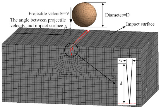
Figure 2.
Finite element model of shot peening for crack repair.
In the finite element model, the diameter of the projectiles (D) was set to 0.5 mm. The pellets undergo free mesh partitioning, while the target material undergoes regular mesh partitioning with a mesh size of 0.02 mm. To verify mesh convergence, follow the steps below: 1. Run the shot-peening finite element model using a baseline mesh size of 0.05 mm and record the output parameters of stress and strain. 2. Utilize adaptive mesh refinement techniques, adjusting the mesh refinement level based on error indicators obtained from simulation results. 3. Run the model with the refined mesh and record the same output parameters. 4. Compare the simulation results between the baseline mesh and the refined mesh, analyzing differences in output parameters to assess convergence. If the variations in output parameters gradually decrease and stabilize with mesh refinement, the simulation is considered convergent. If significant differences persist or no clear trend emerges, further mesh refinement is necessary. During the process of shot peening, the plastic deformation of the projectiles upon impacting the target material can be disregarded. This is due to the significantly greater hardness of the projectile material in comparison to the target material. Additionally, since the primary focus is on studying the target material, the projectiles can be treated as rigid bodies, simplifying the simulation model accordingly. The target material is a 7075-T651 aluminum alloy, and the mechanical properties of the material are provided in Table 2.

Table 2.
Mechanical properties of materials.
The dynamic mechanical response of the target material under the action of a large number of shot blasting loads is characterized using the Johnson-Cook constitutive model, as shown in Equation (1) and Table 3. The graph in Figure 3 depicts the stress-strain curve [29].

Table 3.
Parameters of the Johnson-Cook model for the 7075-T651 aluminum alloy.
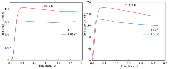
Figure 3.
True stress-strain curves of Al7075.
In the formula, represents the equivalent stress, represents the equivalent plastic strain, and represents the equivalent strain rate, where is the reference strain rate. , where is the room temperature, and is the melting point of material. The terms , , and describe the material’s hardening effect, strain rate strengthening effect, and temperature softening effect, respectively.
All surfaces, except for the one impacted by the projectile, were subjected to non-reflective conditions, with additional fixed constraints applied to the bottom surface. The projectile velocity (V) was defined as 80 m/s and determined by Equation (2).
where the shot peening pressure (P) was 0.5 MPa, the shot peening flow rate (m) was 2 kg/min, and the projectile diameter (D) was 0.5 mm. The angle (A) between the projectile velocity direction and the target material surface was set to 90°. The crack width (w) was 0.05 mm, and the crack depth (d) was 0.15 mm.
During the process of shot peening for crack repair, the continuous impact of projectiles on the target material crack leads to various energy conversion and storage phenomena, including heat release, macroscopic plastic deformation, and storage of strain energy. Among them, macroscopic plastic deformation promotes crack closure, and the stored energy results in interactions within the target material, forming residual compressive stress due to shot peening. This, in turn, promotes the compression of closed cracks, ultimately achieving the goal of crack repair. Figure 4a depicts the residual stress field after one impact of the projectile on the crack, while Figure 4b shows the residual stress field after three impacts. As shown in Figure 4a,b, as the shot peening progresses, plastic deformation increases, and the crack gradually closes. The maximum residual stress after a single impact is 317 MPa, while after three impacts, it reduces to 218 MPa. In comparison to that after a single impact, the residual stress distribution becomes more uniform and covers a larger area after three impacts. This suggests that multiple impacts can equalize the residual stress and expand the peening effect. The depth-wise distribution of residual stress is obtained using the area averaging method, as depicted in Figure 4c. Evidently, due to energy conservation, the cracked region experiences more significant macroscopic plastic deformation, leading to a lower storage of strain energy. Consequently, the residual stress in the cracked region is lower than that in the crack-free region. Simultaneously, it is observed that at a crack depth of 0.15 mm, higher residual stress occurs within the depth range of 0.1 to 0.3 mm, with the peak residual stress concentrating at the crack tip. This phenomenon effectively inhibits crack propagation.
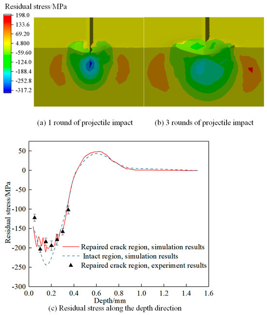
Figure 4.
Shot peening repair crack simulation results.
3.2. Fatigue Test Finite Element Simulation
The modeling of the fatigue test was conducted using DesignModeler, following the geometry of the standard specimen. The specimen model was imported into Workbench, and the mechanical properties of the 7075-T651 aluminum alloy were assigned. Additionally, cracks were introduced at the chamfered edges of the specimen, and a hexahedral mesh was utilized to enhance computational accuracy. Figure 5 illustrates a finite element model of a cracked specimen in conjunction with the material fatigue life S-N curve. The specimen is subjected to fatigue testing following the guidelines outlined in the Chinese standard ‘Metallic Materials—Axial Strain-Controlled Low Cycle Fatigue Testing Method (GB/T 15248-2008).’ The testing involves applying constraints and loading conditions consistent with fatigue tensile testing, as depicted in Figure 6. One end of the specimen is firmly constrained, while a tensile load is applied to the other end. The fatigue life S-N curve corresponding to a stress ratio of R = 0.1 is selected from the software’s material engineering library. The loading is defined as sinusoidal alternating stress with a testing frequency of 78 Hz, and the material fatigue strength factor is set at, .
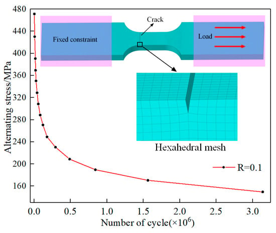
Figure 5.
The finite element model of a cracked specimen and the material fatigue life S-N curve.
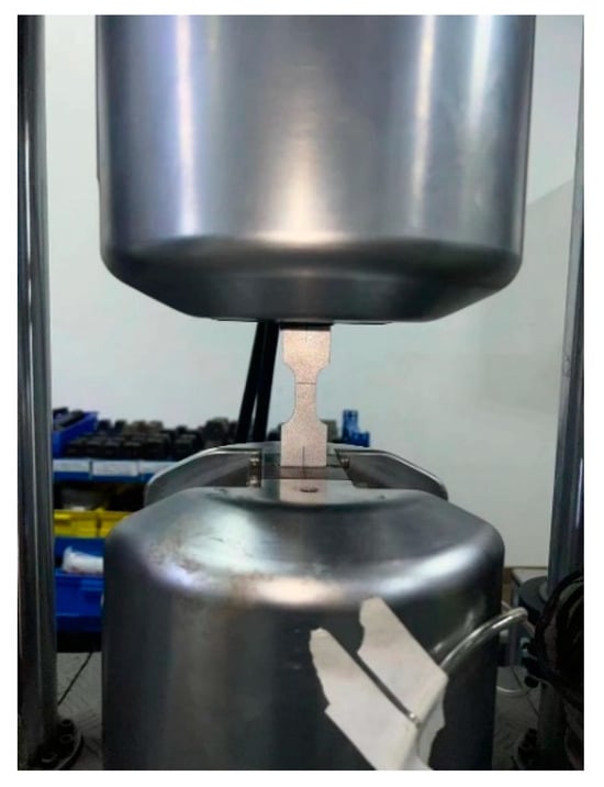
Figure 6.
Fatigue life test.
To investigate the influence of fatigue cracks on the fatigue strength of the specimen, numerical simulations of fatigue were performed on both the cracked specimen and the intact specimen, with a maximum alternating load of 200 MPa. The numerical simulation results are shown in Figure 7. Figure 7a,b presents the fatigue life contour maps for the cracked specimen and the intact specimen, respectively. The minimum fatigue life for the cracked specimen is 1.6531 × 10⁵ cycles, while for the intact specimen, it is 2.2301 × 10⁵ cycles. It can be observed that the presence of cracks reduces the fatigue life of the specimen by 25.87%. Due to energy release at the crack tip, the fracture in the cracked specimen occurs adjacent to the chamfered surface. Figure 7c,d shows the equivalent alternating stresses experienced by the cracked specimen and the intact specimen, respectively. A comparative analysis reveals that the stress on the crack surface is higher than that on the back surface due to the presence of the crack. However, the stress distribution overall is relatively uniform in the middle of the specimen. Stress concentration occurs at the chamfered edges of the specimen, which corresponds to the location of the minimum fatigue life on the chamfered surface. In fatigue testing, the load is applied to the surfaces at both ends of the specimen, and stress is transmitted from the surface to the interior. Additionally, as the specimen narrows from the wider section to the narrower section, stress concentration occurs at the chamfered surface.
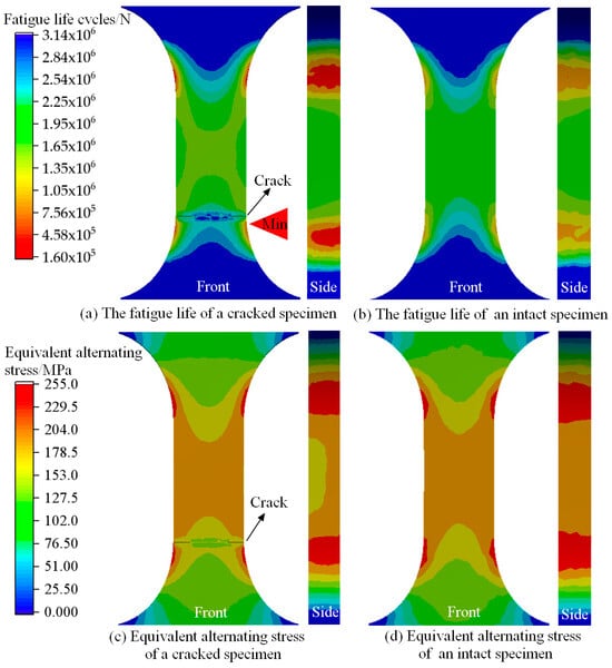
Figure 7.
Simulation results of a fatigue test with a maximum stress of 200 MPa.
4. Multi-Step Simulation of Crack Repair by Shot Peening and Fatigue Testing
Based on the principles of Linear Elastic Fracture Mechanics (LEFM), the introduction of residual compressive stress fields during crack repair by shot peening can effectively inhibit the propagation of fatigue cracks. This inhibitory effect is attributed to the reduction in the crack tip’s energy release rate, which essentially involves the conversion or transfer of energy. In the multi-step simulation of crack repair by shot peening, the introduced compressive stress from shot peening is considered an additional boundary condition, and the changes in the stress field at the crack tip are also taken into consideration. By using appropriate boundary conditions and geometrical shapes, the stress field at the crack tip can be calculated. The Dislocation Stress Field formula is employed to calculate the stress components at the crack tip:
where and are the radial and tangential stress components at the crack tip, is the stress intensity factor at the crack tip, is the radial distance from the crack tip, and is the polar angle at the crack tip.
Using the LEFM theory, the energy release rate at the crack tip can be calculated, which represents the energy required for crack propagation. According to Griffith’s criterion, the energy release rate can be calculated based on the stress intensity factor :
where is Poisson’s ratio and is the elastic modulus.
Adjustments to the stress field and energy release rate at the crack tip are made based on the compressive stress introduced from shot peening. The introduced compressive stress is obtained through simulation calculations and is then superimposed with the stress field at the crack tip. Additionally, shot peening induces crack closure, so the fatigue testing also incorporates the plastic deformation caused by shot peening. The multi-step simulation process is illustrated in Figure 8. The specific simulation conditions are presented in Table 4. It is important to note that the multi-step simulation in this study represents a simplified model, and the actual scenarios are more complex. In practical applications, factors such as nonlinear material behavior, changes in crack morphology, and the relaxation of residual stresses during the fatigue testing process need to be considered.
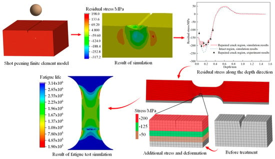
Figure 8.
Multi-step simulation process.

Table 4.
Multi-step simulation cases.
5. Results and Discussion
The objective of this study is to investigate the mechanisms and influencing factors of crack repair in aluminum alloys when using shot peening. The effectiveness of crack repair is evaluated by characterizing the fatigue life of the specimens. The experiment utilized specimens conforming to uniform standards. Cracks, with a width of 0.05 mm and a depth of 0.15 mm, were manufactured using a wire-cutting machine and positioned at the chamfer of the specimen. Multiple sets of shot peening were conducted to repair the cracked specimens, followed by fatigue tests. Each group underwent three repeated trials, and the average of the fatigue test results was calculated based on three experiments.
5.1. Effect of Shot Peening Pressure on Crack Repair
During the shot peening stage, simulations were conducted using 0.3, 0.4, 0.5, and 0.6 MPa shot peening pressures with 0.5 mm diameter projectiles. The resulting residual stresses on the aluminum alloy surface under different shot peening pressures are shown in Figure 9a. Taking the example of a shot peening pressure of 0.5 MPa, the obtained residual stresses were applied to the surface of the specimen, as illustrated in Figure 9b. The simulation results demonstrate that the impact of projectiles can induce crack closure. In the specimen model, a crack with a width of 0.001 mm and a depth of 0.15 mm (initial crack width of 0.05 mm and depth of 0.15 mm) was created to represent a closed crack. Due to the sufficiently small crack width, the crack is considered closed. Fatigue testing was performed on the specimen shown in Figure 9b by applying a maximum alternating load of 200 MPa with a load ratio of 0.1, and the fatigue life of the specimen was obtained, as depicted in Figure 9c. By applying this approach, the fatigue life of aluminum alloy specimens subjected to different shot peening pressures was determined, as shown in Figure 9d. The fatigue life of the specimens serves as an indicator of the effectiveness of crack repair, enabling the investigation of the influence of shot peening pressure on crack repair in aluminum alloys.
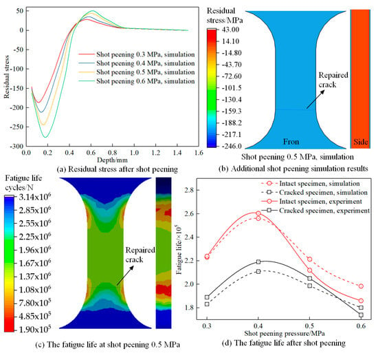
Figure 9.
Effect of shot peening pressure on crack repair.
From Figure 9a, it can be observed that increasing the shot peening pressure significantly increases the residual stress values on the aluminum alloy surface, and the depth of the residual stress layer also increases. Analyzing Figure 9b, it is evident that shot peening can enhance the fatigue life of the aluminum alloy. The most significant improvement in fatigue life is observed at a shot peening pressure of 0.4 MPa, while further increasing the pressure leads to a decrease in the surface strengthening effect. The ratio of fatigue life between the cracked specimen and the intact specimen can be considered an indicator of crack repair effectiveness, denoted as the crack repair ratio (, where is the crack repair ratio, is the fatigue life of the cracked specimen, and is the fatigue life of the intact specimen). The crack repair ratios at the four pressures are 82.1%, 82.4%, 89.8%, and 90.8%, respectively. This indicates that increasing the shot peening pressure slightly improves the crack repair ratio, but it does not necessarily result in an increase in the fatigue life of the specimen. Higher pressure shot peening can damage the surface structure of the material and promote the initiation of new cracks, leading to a decrease in fatigue life. For the crack model used in this study (crack depth of 0.15 mm, width of 0.05 mm), the maximum fatigue life and crack repair ratio are achieved at a shot peening pressure of 0.4 MPa, with a crack repair ratio of 82.4%.
5.2. Effect of Projectile Size on Crack Repair
During the shot peening stage, simulations were conducted using projectiles with diameters of 0.3, 0.4, 0.5, and 0.6 mm at a shot peening pressure of 0.4 MPa. The resulting residual stresses on the aluminum alloy surface under different projectile sizes are shown in Figure 9a. The residual stresses obtained from different shot peening processes were introduced into the fatigue specimens, and fatigue life simulations were performed according to the previously described method and conditions. The fatigue lives of the specimens under different projectile sizes are depicted in Figure 10b. Figure 10a demonstrates that increasing the projectile size leads to an increase in the depth of the residual stress layer and the maximum residual stress value, although the increase is not substantial. Figure 10b reveals that larger projectile sizes result in a decrease in the fatigue life of the strengthened material. This is attributed to the fact that larger projectiles increase the surface roughness of the material, leading to a decrease in the uniformity of the surface residual stress layer and an increased likelihood of stress concentration on the material surface, which facilitates crack initiation during fatigue testing. However, from the perspective of crack repair, larger projectile sizes significantly improve the crack repair ratio. This is because larger projectiles induce greater plastic deformation on the material surface, enhancing the healing of the crack and improving the crack repair ratio. For the crack model used in this study, the specimen exhibits the maximum fatigue life and a crack repair ratio of 74.3% when using a projectile diameter of 0.3 mm.
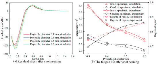
Figure 10.
Effect of projectile size on crack repair.
5.3. Effect of Tensile Load on Crack Repair
During the shot peening stage, aluminum alloy surfaces were subjected to a simulation using 0.5 mm diameter projectiles at 0.4 MPa, resulting in residual stresses. These residual stresses were introduced into the fatigue specimens. Fatigue test simulations were then conducted using the methodology previously described. The maximum alternating loads were set at 150, 180, 210, and 240 MPa. This yielded fatigue lifetimes for specimens under the same shot peening conditions, as depicted in Figure 11. Increasing the tensile load led to a significant reduction in material fatigue life, which is governed by the material’s fatigue behavior. Notably, at different tensile loads, the ratio of fatigue lifetimes between cracked and uncracked specimens denoted different levels of crack closure. Specifically, at 150, 180, 210, and 240 MPa loads, the crack closure ratios were 85.28%, 82.04%, 76.10%, and 53.06%, respectively. This trend indicates a higher crack closure at lower loads and a lower closure at higher loads. The crack closure decreased with an increasing load, and there was a more pronounced effect at higher loads. Consequently, repaired cracks were more susceptible to fracture at elevated loads compared to intact specimens, leading to reduced fatigue lifetimes.
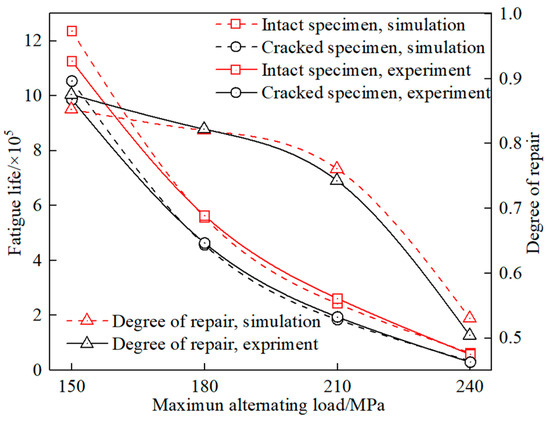
Figure 11.
Effect of tensile load on crack repair.
6. Conclusions
(1) The maximum deviation between the experimental and multi-step simulation results for fatigue life was 14.07%, with a difference of 4080 cycles. This substantial agreement highlights the high fidelity of the multi-step simulation model and approach in accurately simulating the crack repair process of shot-peened aluminum alloy. This methodology is capable of optimizing parameters and processes for crack repair through shot peening.
(2) For the aluminum alloy cracks investigated in this study (crack depth of 0.15 mm, width of 0.05 mm), employing 0.3 mm diameter projectiles at a pressure of 0.4 MPa during shot peening achieved fatigue lifetimes ranging from 82% to 90% compared to that of the standard specimen. This was the most effective crack repair technique.
(3) Increasing both the shot peening pressure and projectile size enhanced the crack closure. However, a higher pressure can damage the surface microstructure, while larger projectiles may lead to increased surface roughness, both contributing to a reduced fatigue life.
(4) In the 150 MPa load fatigue test, crack-repaired specimens exhibited a fatigue life of 85.28% compared to that of the standard specimen. This demonstrates the positive effect of shot peening on the early-stage and emergency repair of cracks in aluminum alloy structural components.
Author Contributions
Conceptualization, J.Z., and K.L.; methodology, J.Z., and J.H.; validation, J.H., and K.L.; formal analysis, J.Z.; investigation, J.Z., and J.H.; resources, J.H., and K.L.; writing—original draft preparation, J.Z.; writing—review and editing, K.L.; supervision, K.L.; project administration, K.L.; funding acquisition, K.L. All authors have read and agreed to the published version of the manuscript.
Funding
This research was Supported by the National Key Research and Development Program of China (2022YFD2202103); National Natural Science Foundation of China (51475483).
Institutional Review Board Statement
Written informed consent has been obtained from the patients to publish this paper.
Data Availability Statement
The data that supports the findings of this study are available from the corresponding author upon reasonable request.
Conflicts of Interest
The authors declare no conflict of interest.
Nomenclature
| V | The speed of the projectiles during shot peening. |
| Projectile diameter. | |
| The shot peening pressure. | |
| The Poisson’s ratio of a material. | |
| The density of the material. | |
| E | The elastic modulus of the material. |
| The yield strength of the material. | |
| G | The shear modulus of the material. |
| σ | The flow stress. |
| A | The flow stress at the yield point of the material under the reference condition. |
| B | The constants that illustrate the characteristics of the material. |
| ε | The corresponding plastic strain. |
| n | Strain hardening exponent. |
| C | Strain rate sensitivity coefficient. |
| Strain rate factor. | |
| T | Temperature factor. |
| The room temperature. | |
| The melting point of material. | |
| h | Temperature sensitivity coefficient. |
| m | The shot peening flow rate. |
| d | The crack depth. |
| w | The crack width. |
| S-N | The relationship between stress and the number of cycles. |
| R | The stress ratio. |
| The material fatigue strength factor. | |
| The radial stress components at the crack tip. | |
| The tangential stress components at the crack tip. | |
| The stress intensity factor at the crack tip. | |
| The radial distance from the crack tip. | |
| The polar angle at the crack tip. | |
| LEFM | Linear Elastic Fracture Mechanics. |
| The energy release rate. | |
| The crack repair ratio. | |
| The fatigue life of the cracked specimen. | |
| The fatigue life of the intact specimen. |
References
- Xu, T.; Li, G.; Xie, M.; Liu, M.; Zhang, D.; Zhao, Y.; Chen, G.; Kai, X. Microstructure and mechanical properties of in-situ nano γ-Al2O3p/A356 aluminum matrix composite. J. Alloys Compd. 2019, 787, 72–85. [Google Scholar] [CrossRef]
- Song, X.Y.; Wang, Y.J.; Zhang, J.X.; Du, D.A.; Yang, H.Y.; Zhao, L.; Peng, F.; Li, X.; Qiu, F. Microstructure and mechanical properties of aluminum alloy composites with endogenous nano-TiCp. Ceram. Int. 2023, 49, 6923–6931. [Google Scholar] [CrossRef]
- Ganiev, I.N.; Rakhimova, N.O.; Kurbonova, M.Z.; Davlatzoda, F.S.; Yakubov, U.S. Effect of Titanium Additions on the Corrosion and Electrochemical Properties of Aluminum Alloy AB1. Inorg. Mater. 2022, 58, 893–897. [Google Scholar] [CrossRef]
- Valdez, B.; Kiyota, S.; Stoytcheva, M.; Zlatev, R.; Bastidas, J.M. Cerium-based conversion coatings to improve the corrosion resistance of aluminum alloy 6061-T6. Corros. Sci. 2014, 87, 141–149. [Google Scholar] [CrossRef]
- Wang, Y.L.; Zhu, Y.L.; Hou, S.; Sun, H.X.; Zhou, Y. Investigation on fatigue performance of cold expansion holes of 6061-T6 aluminum alloy. Int. J. Fatigue 2017, 95, 216–228. [Google Scholar] [CrossRef]
- Chang, J.; Wang, Z.; Zhu, Q.; Wang, Z. SVR Prediction Algorithm for Crack Propagation of Aviation Aluminum Alloy. J. Math. 2020, 2020, 1034639. [Google Scholar] [CrossRef]
- Hu, Y.; Cheng, H.; Yu, J.; Yao, Z. An experimental study on crack closure induced by laser peening in pre-cracked aluminum alloy 2024-T351 and fatigue life extension. Int. J. Fatigue 2019, 130, 105232. [Google Scholar] [CrossRef]
- Trško, L.; Guagliano, M.; Bokůvka, O.; Nový, F.; Jambor, M.; Florková, Z. Influence of severe shot peening on the surface state and ultrahigh-cycle fatigue behavior of an AW 7075 aluminum alloy. J. Mater. Eng. Perform. 2017, 26, 2784–2797. [Google Scholar] [CrossRef]
- Maleki, E.; Unal, O.; Kashyzadeh, K.R. Effects of conventional, severe, over, and re-shot peening processes on the fatigue behavior of mild carbon steel. Surf. Coat. Technol. 2018, 344, 62–74. [Google Scholar] [CrossRef]
- Wang, C.; Lai, Y.; Wang, L.; Wang, C. Dislocation-based study on the influences of shot peening on fatigue resistance. Surf. Coat. Technol. 2020, 383, 125247. [Google Scholar] [CrossRef]
- Keller, S.; Horstmann, M.; Kashaev, N.; Klusemann, B. Experimentally validated multi-step simulation strategy to predict the fatigue crack propagation rate in residual stress fields after laser shock peening. Int. J. Fatigue 2019, 124, 265–276. [Google Scholar] [CrossRef]
- Keller, S.; Horstmann, M.; Kashaev, N.; Klusemann, B. Crack closure mechanisms in residual stress fields generated by laser shock peening: A combined experimental-numerical approach. Eng. Fract. Mech. 2019, 221, 106630. [Google Scholar] [CrossRef]
- Lv, Z.; Hou, R.; Wang, R.; Zhang, Y.; Zhang, M. Numerical investigation on the residual stress in abrasive waterjet peening. Int. J. Adv. Manuf. Technol. 2022, 123, 1695–1706. [Google Scholar] [CrossRef]
- Ohta, T.; Ma, N. Shot velocity measurement using particle image velocimetry and a numerical analysis of the residual stress in fine particle shot peening. J. Manuf. Process. 2020, 58, 1138–1149. [Google Scholar] [CrossRef]
- Zhang, X.; Huang, J.; Niu, Z.; Zhong, Y.; Zhou, W.; Chen, G.; Fu, X. Analysis of shot peening residual stress distribution based on dislocation configuration. Mater. Sci. Technol. 2022, 38, 1257–1265. [Google Scholar] [CrossRef]
- Zhang, H.W.; Zhang, Y.D.; Qiong, W.U. Three-dimensional numerical analysis of residual stress field for shot-peening. J. Aerosp. Power 2010, 25, 603–609. [Google Scholar]
- Zhang, H.W.; Zhang, Y.D.; Zhao, X.C. Numerical analysis of residual stress field for shot-peening process based on Kriging model. J. Syst. Simul. 2011, 23, 826–831. [Google Scholar]
- Zhang, H.-W.; Chen, J.-Q.; Zhang, Y.-D. Numerical simulation of shot-peening process based on multiple shot model. J. Plast. Eng. 2012, 19, 118–125. [Google Scholar]
- Chen, J.-W.; Liao, K.; Che, X.-F.; Zhong, L.-P.; Xi, H. Simulation and experiment study of surface stress-deformation by shot peening on Al-based alloy. Surf. Technol. 2018, 47, 41–47. [Google Scholar]
- Chen, J.-W.; Liao, K.; Li, L.-J.; Gao, Z.-C.; Chen, H.; Xi, H. Function relationship between shot peening parameters and surface characteristic of Al-based alloy and application. Surf. Technol. 2019, 48, 212–220. [Google Scholar]
- Jiali, B.U.; Yang, L.Ü.; Bozhi, L.I.U.; Zhenyu, H.A.N.; Wenwei, T.O.N.G.; Zhikun, G.A.O. Effect of different shot peening strength on fatigue resistance of TC17 titanium alloy. J. Aerosp. Power 2022, 37, 1225–1233. [Google Scholar]
- Tuninetti, V.; Jaramillo, A.F.; Riu, G.; Rojas-Ulloa, C.; Znaidi, A.; Medina, C.; Mateo, A.M.; Roa, J.J. Experimental Correlation of Mechanical Properties of the Ti-6Al-4V Alloy at Different Length Scales. Metals 2021, 11, 104. [Google Scholar] [CrossRef]
- Rojas-Ulloa, C.; Bouffioux, C.; Jaramillo, A.F.; García-Herrera, C.M.; Hussain, T.; Duchêne, L.; Riu, G.; Josep Roa, J.; Flores, P.; Marie Habraken, A.; et al. Nanomechanical Characterization of the Deformation Response of Orthotropic Ti–6Al–4V. Adv. Eng. Mater. 2021, 23, 2001341. [Google Scholar] [CrossRef]
- Węglewski, W.; Pitchai, P.; Bochenek, K.; Bolzon, G.; Konetschnik, R.; Sartory, B.; Ebner, R.; Kiener, D.; Basista, M. Experimental and Numerical Investigation of the Deformation and Fracture Mode of Microcantilever Beams Made of Cr(Re)/Al2O3 Metal–Matrix Composite. Metall. Mater. Trans. A 2020, 51, 2377–2390. [Google Scholar] [CrossRef]
- Wu, G.; Wang, Z.; Gan, J.; Yang, Y.; Meng, Q.; Wei, S.; Huang, H. FE analysis of shot-peening-induced residual stresses of AISI 304 stainless steel by considering mesh density and friction coefficient. Surf. Eng. 2019, 35, 242–254. [Google Scholar] [CrossRef]
- Rodriguez-Sanchez, J.E.; Rodriguez-Castellanos, A.; Perez-Guerrero, F. Shot Peening Effect on Fatigue Crack Repaired Weldments. Adv. Mater. Sci. Eng. 2017, 2017, 3720403. [Google Scholar] [CrossRef]
- Lucon, E. An assessment of different approaches for measuring crack sizes in fatigue and fracture mechanics specimens. Theor. Appl. Fract. Mech. 2021, 116, 103119. [Google Scholar] [CrossRef]
- Arakawa, J.; Hayashi, Y.; Akebono, H.; Sugeta, A. Effectiveness of Ultrasonic Shot Peening on Stainless Cast Steel SCS6 Containing a Fatigue Crack. J. Soc. Mater. Sci. Jpn. 2019, 68, 897–903. [Google Scholar] [CrossRef]
- Rasaee, S.; Mirzaei, A.H.; Almasi, D. Constitutive modelling of Al7075 using the Johnson–Cook model. Bull. Mater. Sci. 2020, 43, 23. [Google Scholar] [CrossRef]
Disclaimer/Publisher’s Note: The statements, opinions and data contained in all publications are solely those of the individual author(s) and contributor(s) and not of MDPI and/or the editor(s). MDPI and/or the editor(s) disclaim responsibility for any injury to people or property resulting from any ideas, methods, instructions or products referred to in the content. |
© 2023 by the authors. Licensee MDPI, Basel, Switzerland. This article is an open access article distributed under the terms and conditions of the Creative Commons Attribution (CC BY) license (https://creativecommons.org/licenses/by/4.0/).