
Influence of Plasma Arc Current on the Friction and Wear Properties of CoCrFeNiMn High Entropy Alloy Coatings Prepared on CGI through Plasma Transfer Arc Cladding

 ,
, 


Abstract
:1. Introduction
2. Materials and Methods
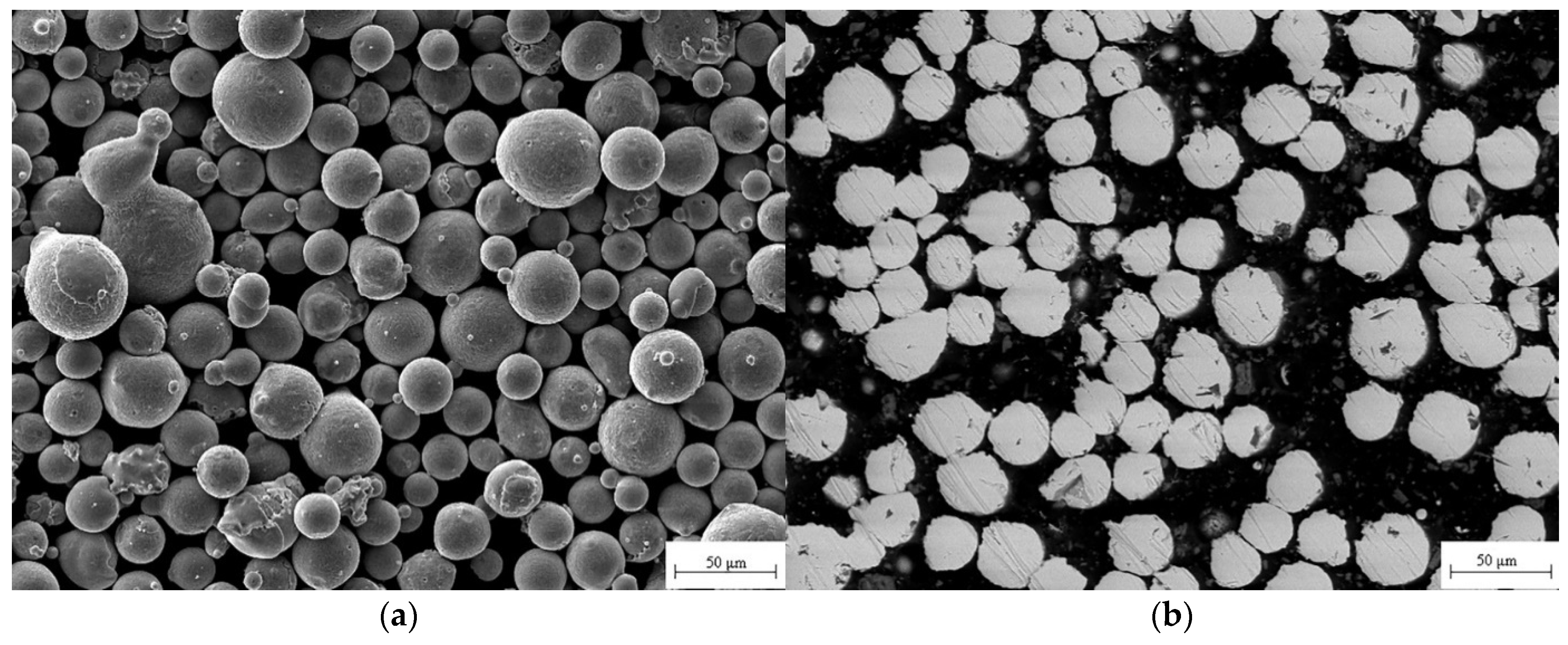
2.1. Preparation of the HEA Coatings
2.2. Characterization of the HEA Coatings
2.3. Wear Test
3. Results and Discussions
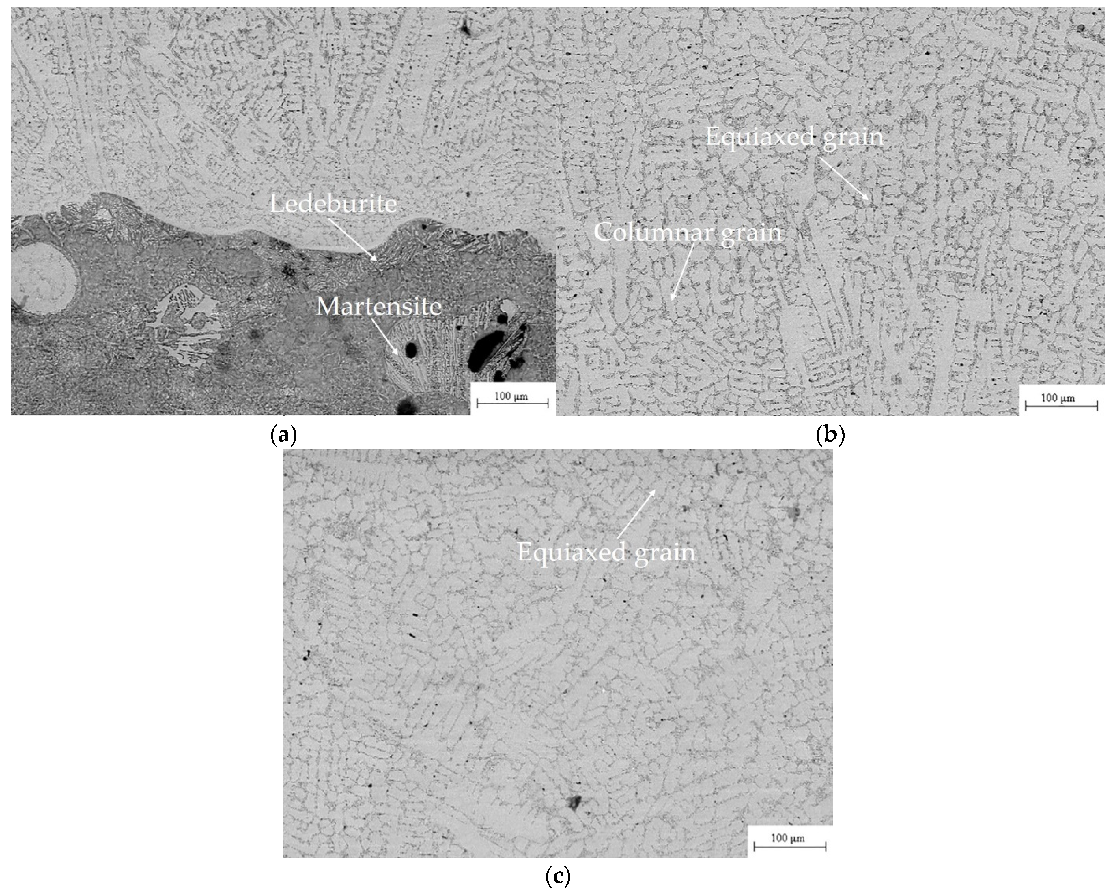
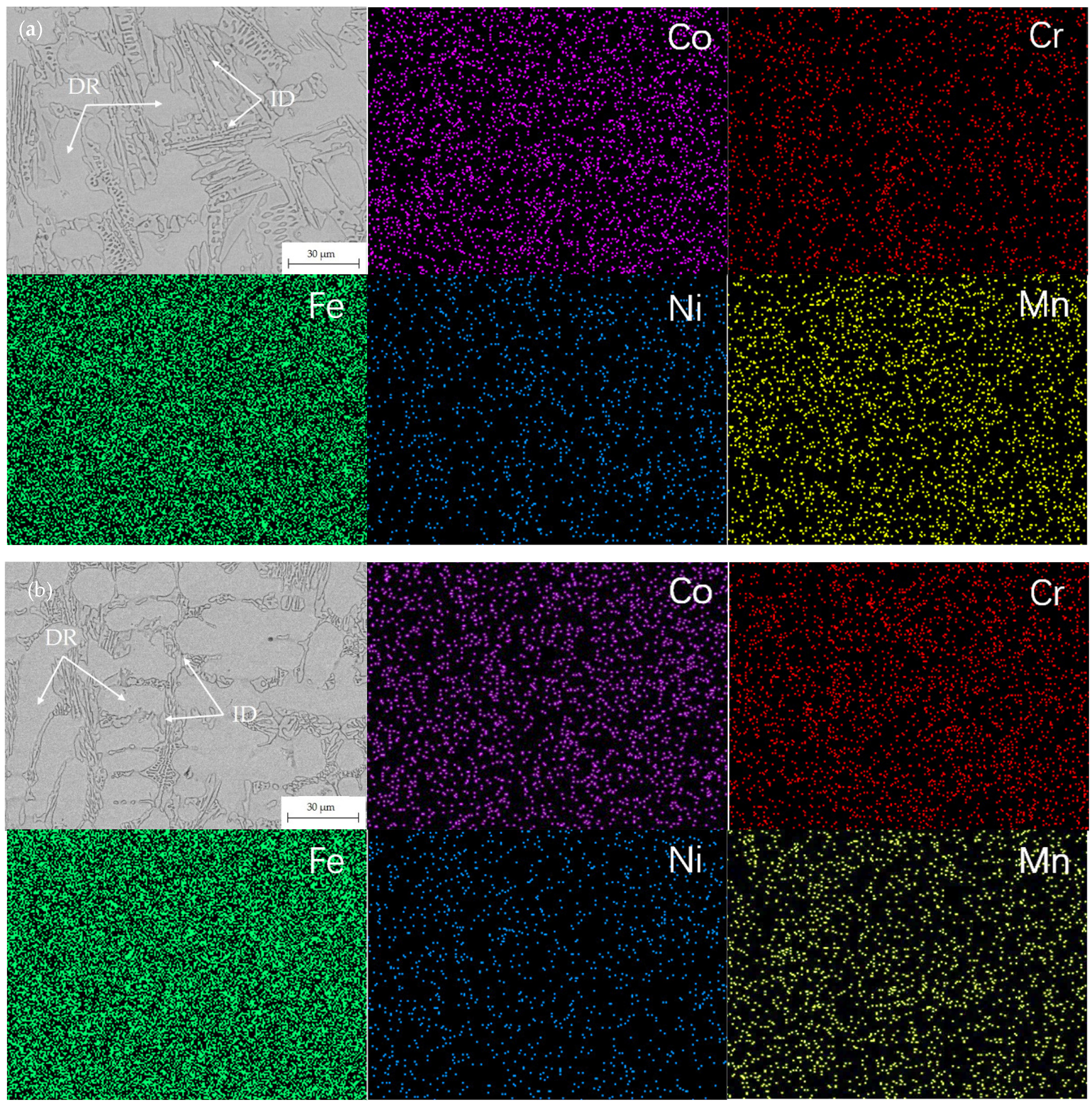
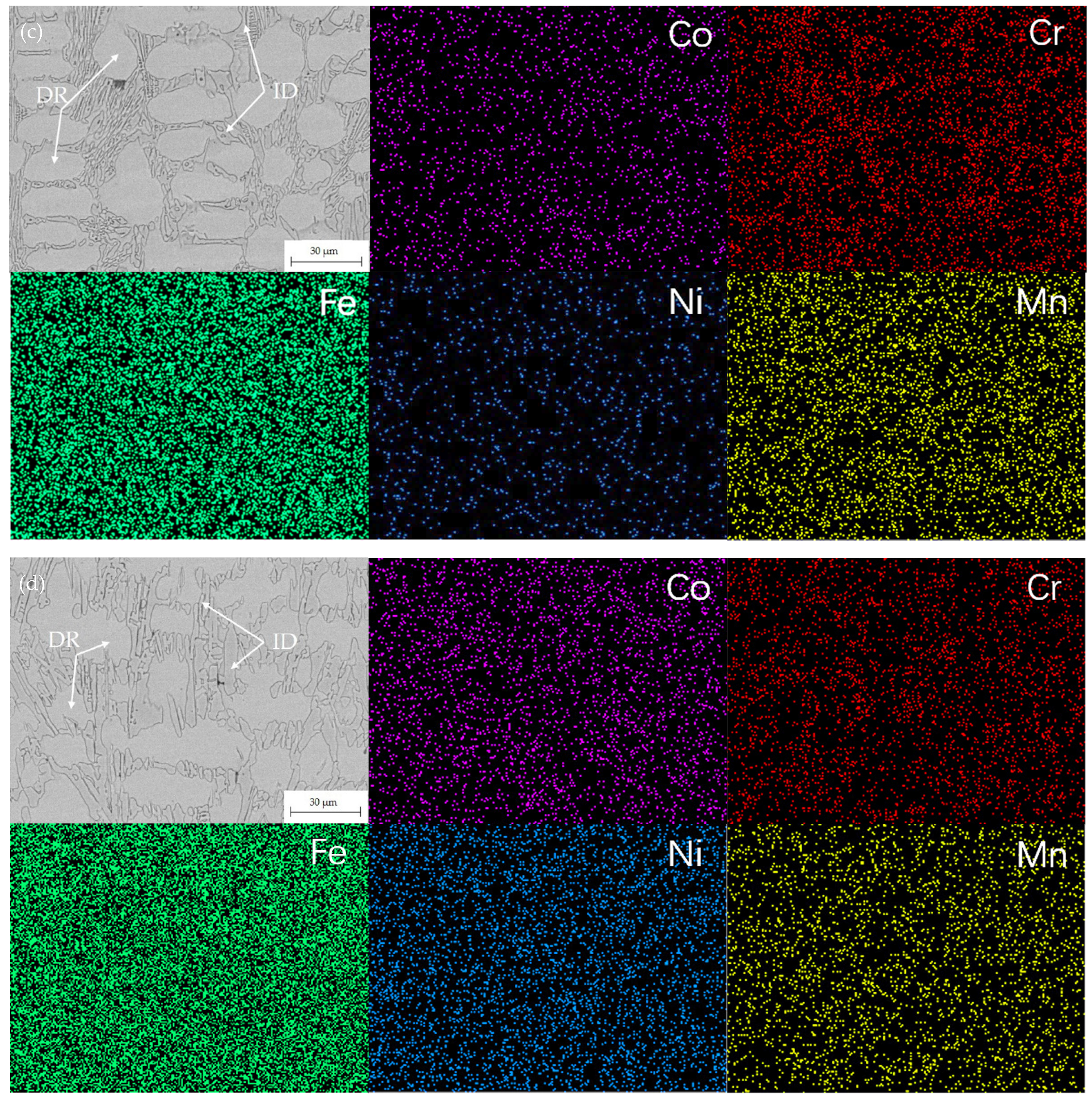
3.1. Microstructure of the HEA Feedstock and Coatings
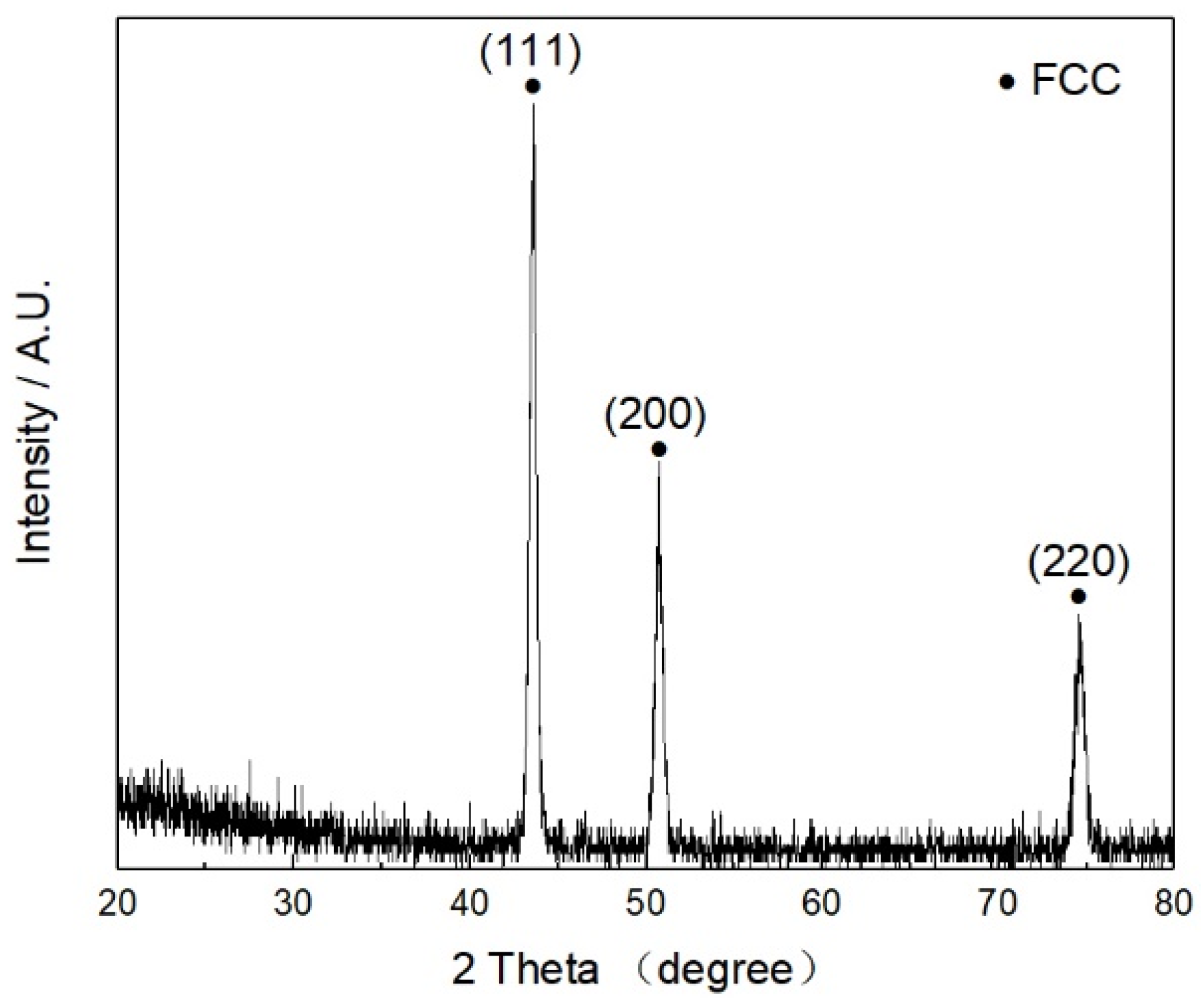
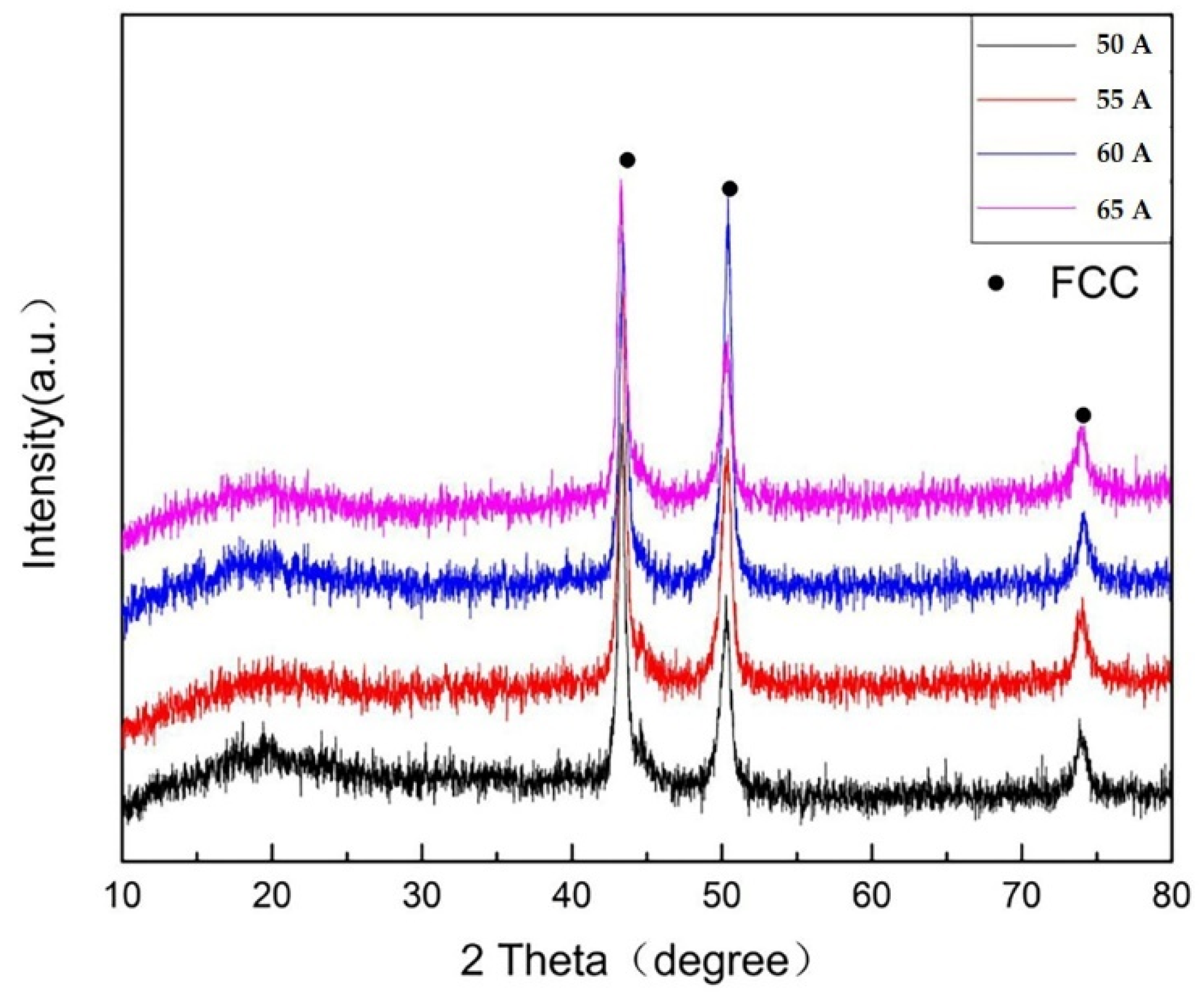
3.2. Phases
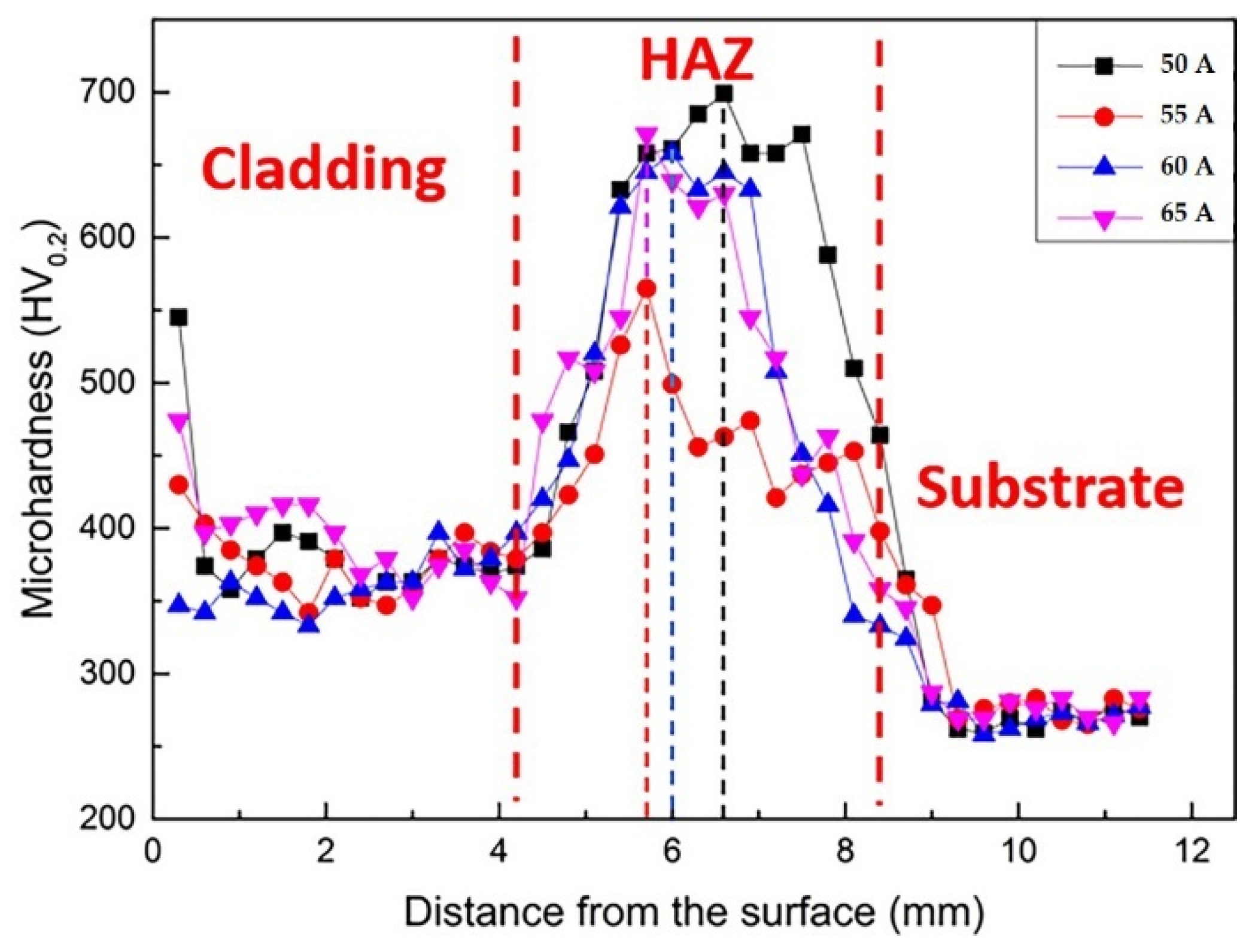
3.3. Microhardness
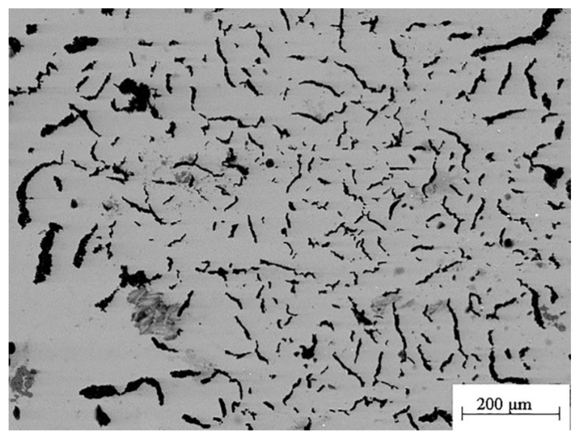
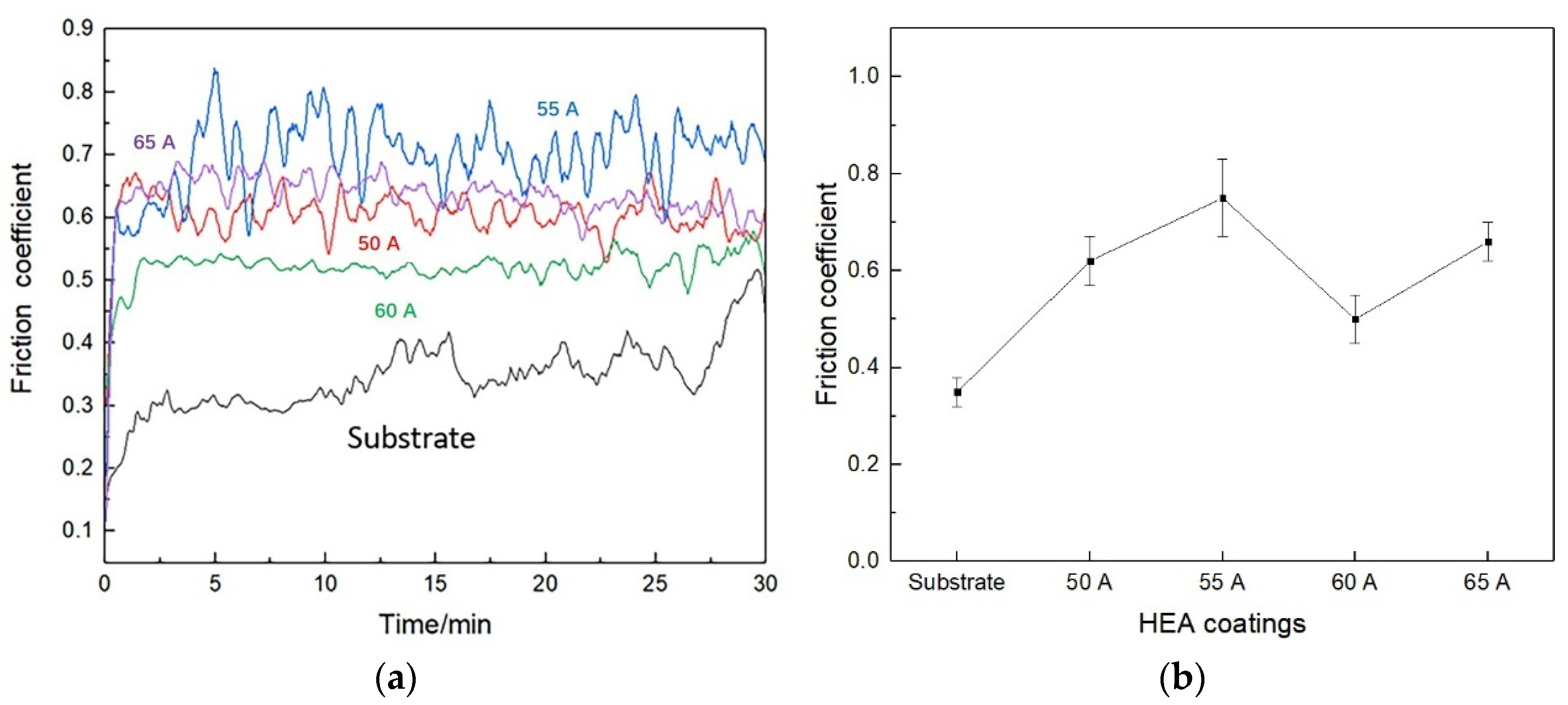
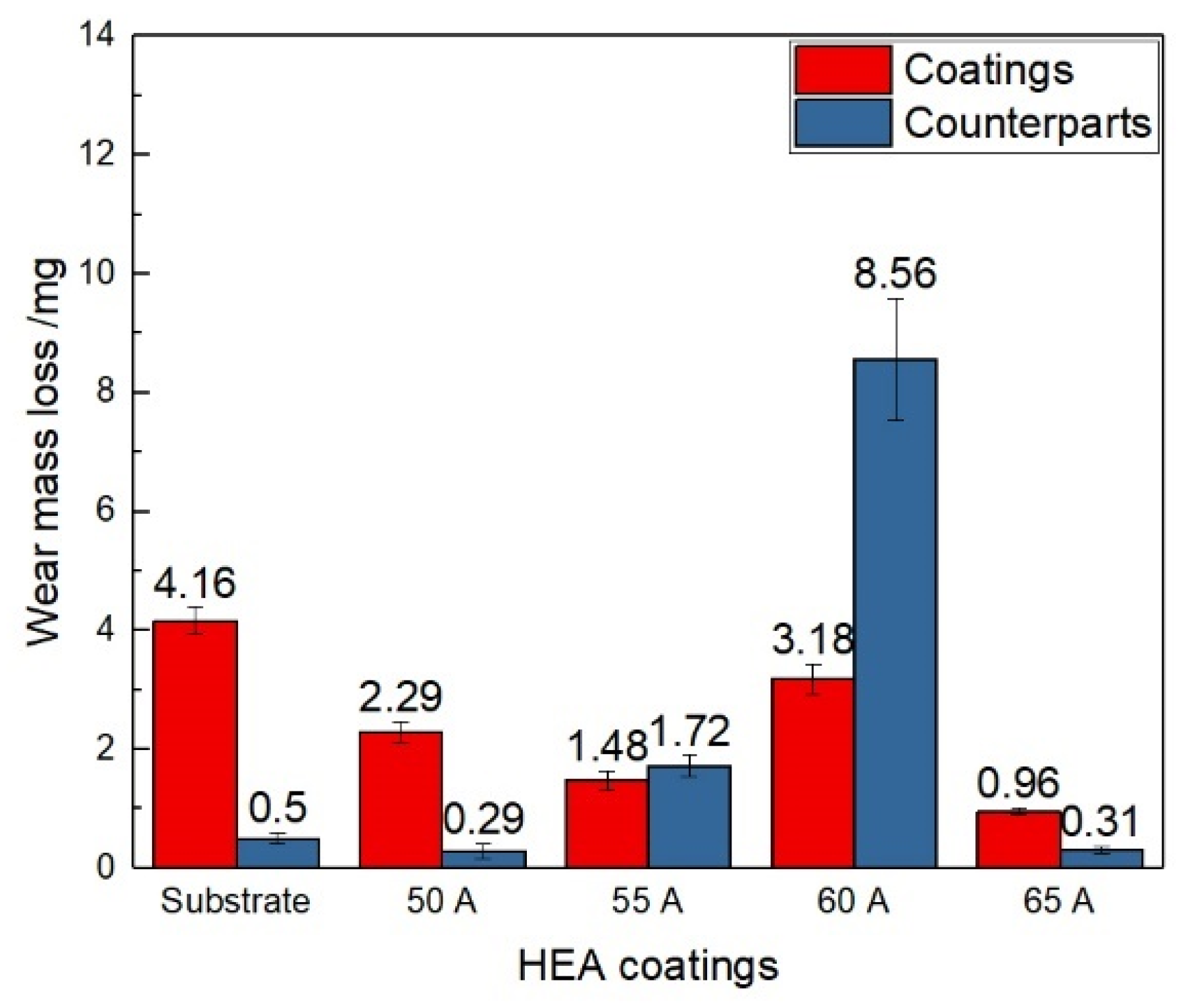
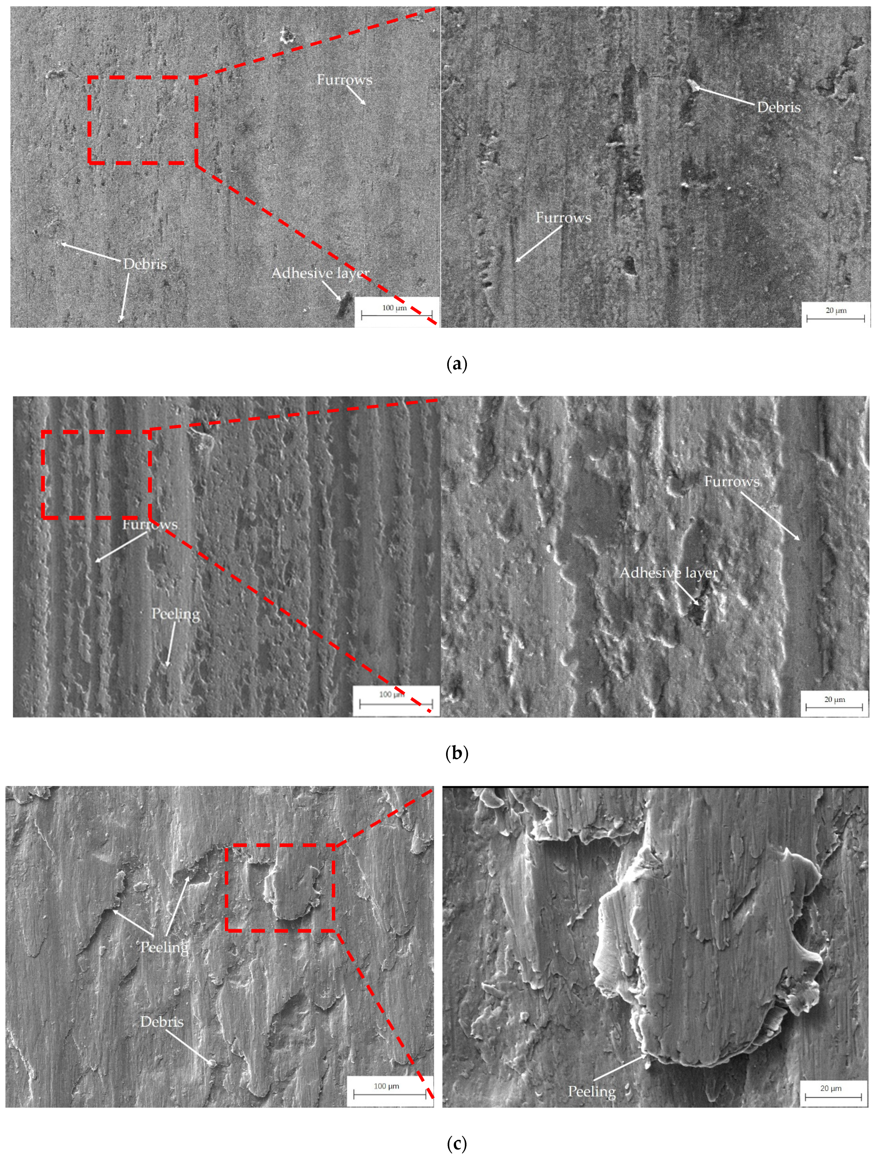
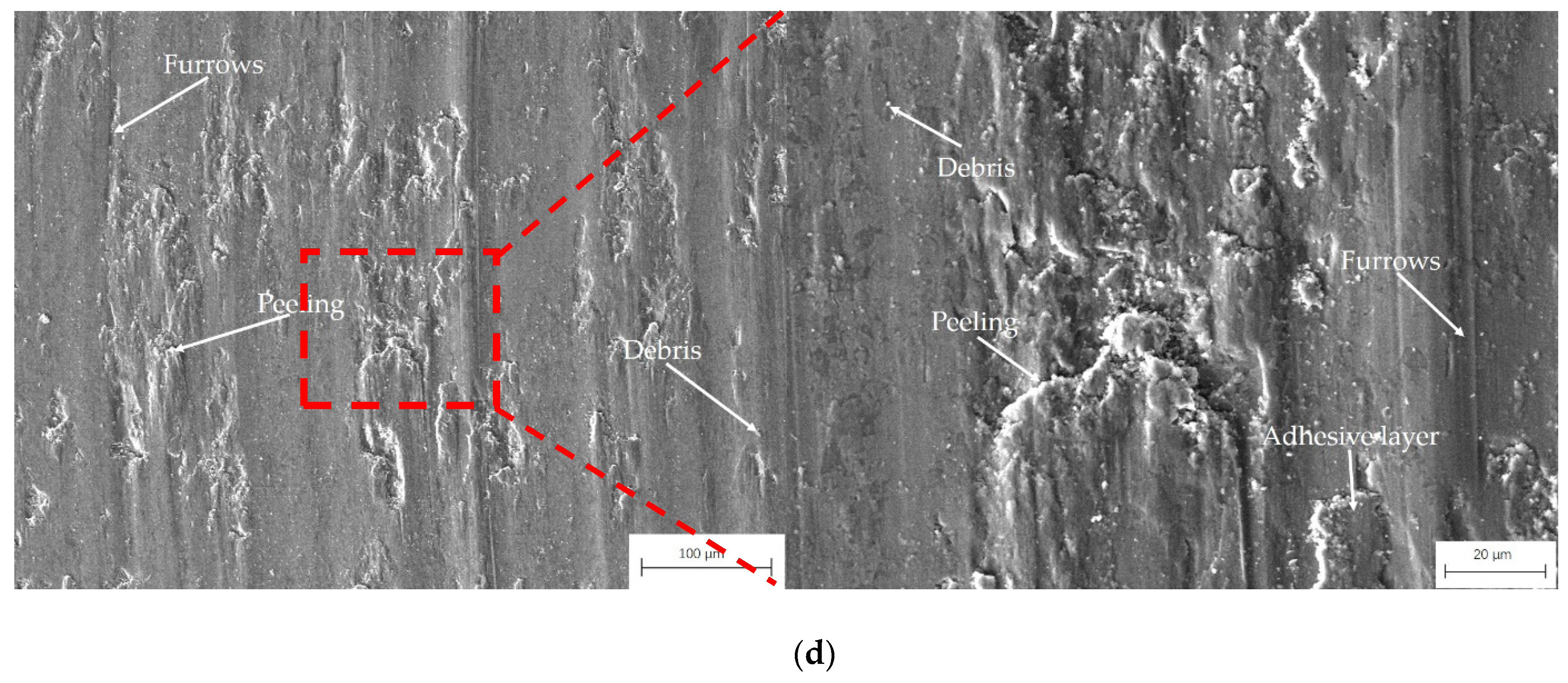
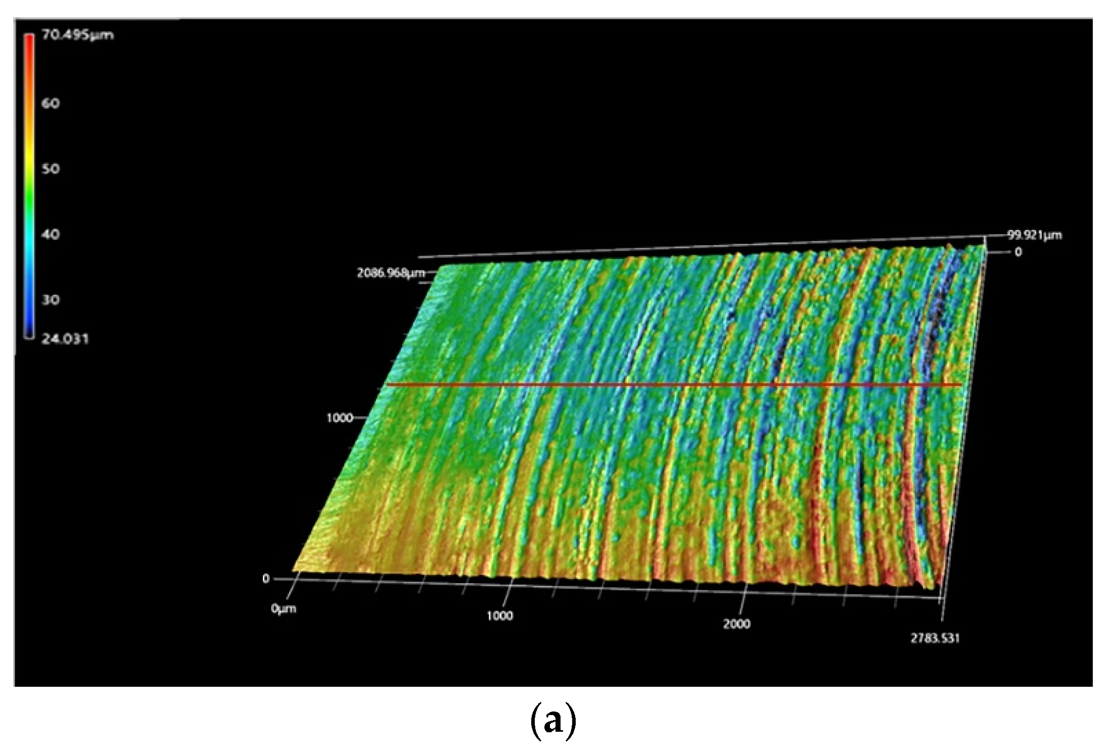
3.4. Wear Resistance
4. Conclusions
- The CoCrFeNiMn HEA coating consisted mainly of martensite and ledeburite in the bonding zone, columnar and equiaxed grains in the middle of the coating and equiaxed grains in the top zone of the coating. The HEA coating had a simple face-centered-cubic solid solution structure similar to the powder.
- The CoCrFeNiMn HEA coating had the highest microhardness of 394 ± 21.6 HV0.2 and the lowest wear mass loss when the plasma arc current was 65 A.
- The CoCrFeNiMn HEA coating had mean friction coefficients ranging from 0.5 to 0.75, which were all higher than that of the compacted graphite iron substrate.
- There were abrasive, adhesive and oxidation wear forms in the HEA coatings against N80 friction pair. The HEA coating presented higher friction coefficient and better wear resistance than compacted graphite iron.
Author Contributions
Funding
Institutional Review Board Statement
Informed Consent Statement
Data Availability Statement
Conflicts of Interest
References
- Yeh, J.-W.; Chen, S.K.; Lin, S.-J.; Gan, J.-Y.; Chin, T.-S.; Shun, T.-T.; Tsau, C.-H.; Chang, S.-Y. Nanostructured High-Entropy Alloys with Multiple Principal Elements: Novel Alloy Design Concepts and Outcomes. Adv. Eng. Mater. 2004, 6, 299–303. [Google Scholar] [CrossRef]
- Zhang, Y.; Zuo, T.T.; Tang, Z.; Gao, M.C.; Dahmen, K.A.; Liaw, P.K.; Lu, Z.P. Microstructures and properties of high-entropy alloys. Prog. Mater. Sci. 2014, 61, 1–93. [Google Scholar] [CrossRef]
- Guo, Y.; Shang, X.; Liu, Q. Microstructure and properties of in-situ TiN reinforced laser cladding CoCr2FeNiTi high-entropy alloy composite coatings. Surf. Coat. Technol. 2018, 344, 353–358. [Google Scholar] [CrossRef]
- Pogrebnjak, A.; Yakushchenko, I.; Bagdasaryan, A.; Bondar, O.; Krause-Rehberg, R.; Abadias, G.; Chartier, P.; Oyoshi, K.; Takeda, Y.; Beresnev, V.; et al. Microstructure, physical and chemical properties of nanostructured (Ti–Hf–Zr–V–Nb)N coatings under different deposition conditions. Mater. Chem. Phys. 2014, 147, 1079–1091. [Google Scholar] [CrossRef]
- Sun, Z.; Li, X.; Wang, Z. Microstructure and mechanical properties of low activation Fe–Ti–Cr–V–W multi-principal element alloys. J. Nucl. Mater. 2020, 533, 152078. [Google Scholar] [CrossRef]
- Yang, X.; Zhang, Y. Prediction of high-entropy stabilized solid-solution in multi-component alloys. Mater. Chem. Phys. 2012, 132, 233–238. [Google Scholar] [CrossRef]
- Dong, Y.; Zhou, K.; Lu, Y.; Gao, X.; Wang, T.; Li, T. Effect of vanadium addition on the microstructure and properties of AlCoCrFeNi high entropy alloy. Mater. Des. 2014, 57, 67–72. [Google Scholar] [CrossRef]
- Zhao, Y.; Qiao, J.; Ma, S.; Gao, M.; Yang, H.; Chen, M.; Zhang, A. A hexagonal close-packed high-entropy alloy: The effect of entropy. Mater. Des. 2016, 96, 10–15. [Google Scholar] [CrossRef]
- Inoue, A.; Makino, A.; Mizushima, T. Ferromagnetic bulk glassy alloys. J. Magn. Magn. Mater. 2000, 215–216, 246–252. [Google Scholar] [CrossRef]
- Wang, J.; Zheng, Z.; Xu, J.; Wang, Y. Microstructure and magnetic properties of mechanically alloyed FeSiBAlNi (Nb) high entropy alloys. J. Magn. Magn. Mater. 2014, 355, 58–64. [Google Scholar] [CrossRef]
- Yang, T.; Zhao, Y.L.; Tong, Y.; Jiao, Z.B.; Wei, J.; Cai, J.X.; Han, X.D.; Chen, D.; Hu, A.; Kai, J.J.; et al. Multicomponent intermetallic nanoparticles and superb mechanical behaviors of complex alloys. Science 2018, 362, 933–937. [Google Scholar] [CrossRef] [PubMed] [Green Version]
- Fu, Z.; Jiang, L.; Wardini, J.L.; MacDonald, B.E.; Wen, H.; Xiong, W.; Zhang, D.; Zhou, Y.; Rupert, T.J.; Chen, W.; et al. A high-entropy alloy with hierarchical nanoprecipitates and ultrahigh strength. Sci. Adv. 2018, 4, eaat8712. [Google Scholar] [CrossRef] [PubMed] [Green Version]
- Zou, Y.; Ma, H.; Spolenak, R. Ultrastrong ductile and stable high-entropy alloys at small scales. Nat. Commun. 2015, 6, 7748. [Google Scholar] [CrossRef] [PubMed] [Green Version]
- Yao, Y.; Huang, Z.; Xie, P.; Lacey, S.D.; Jacob, R.J.; Xie, H.; Chen, F.; Nie, A.; Pu, T.; Rehwoldt, M.; et al. Carbothermal shock synthesis of high-entropy-alloy nanoparticles. Science 2018, 359, 1489–1494. [Google Scholar] [CrossRef] [Green Version]
- El-Atwani, O.; Li, N.; Li, M.; Devaraj, A.; Baldwin, J.K.S.; Schneider, M.M.; Sobieraj, D.; Wróbel, J.S.; Nguyen-Manh, D.; Maloy, S.A.; et al. Outstanding radiation resistance of tungsten-based high-entropy alloys. Sci. Adv. 2019, 5, eaav2002. [Google Scholar] [CrossRef] [Green Version]
- Qiu, Y.; Thomas, S.; Gibson, M.A.; Fraser, H.L.; Birbilis, N. Corrosion of high entropy alloys. NPJ Mater. Degrad. 2017, 1, 15. [Google Scholar] [CrossRef]
- Chuang, M.-H.; Tsai, M.-H.; Wang, W.-R.; Lin, S.-J.; Yeh, J.-W. Microstructure and wear behavior of AlxCo1.5CrFeNi1.5Tiy high-entropy alloys. Acta Mater. 2011, 59, 6308–6317. [Google Scholar] [CrossRef]
- Zhang, S.; Wu, C.; Yi, J.; Zhang, C. Synthesis and characterization of FeCoCrAlCu high-entropy alloy coating by laser surface alloying. Surf. Coat. Technol. 2015, 262, 64–69. [Google Scholar] [CrossRef]
- Moazzen, P.; Toroghinejad, M.R.; Zargar, T.; Cavaliere, P. Investigation of hardness, wear and magnetic properties of NiCoCrFeZrx HEA prepared through mechanical alloying and spark plasma sintering. J. Alloys Compd. 2022, 892, 161924. [Google Scholar] [CrossRef]
- Nagarjuna, C.; Jeong, K.Y.; Lee, Y.; Woo, S.M.; Hong, S.I.; Kim, H.S.; Hong, S.-J. Strengthening the mechanical properties and wear resistance of CoCrFeMnNi high entropy alloy fabricated by powder metallurgy. Adv. Powder Technol. 2022, 33, 103519. [Google Scholar] [CrossRef]
- Hassan, M.A.; Ghayad, I.; Mohamed, A.; El-Nikhaily, A.E.; Elkady, O.A. Improvement ductility and corrosion resistance of CoCrFeNi and AlCoCrFeNi HEAs by electroless copper technique. J. Mater. Res. Technol. 2021, 13, 463–485. [Google Scholar] [CrossRef]
- Lai, C.-H.; Lin, S.-J.; Yeh, J.-W.; Chang, S.-Y. Preparation and characterization of AlCrTaTiZr multi-element nitride coatings. Surf. Coat. Technol. 2006, 201, 3275–3280. [Google Scholar] [CrossRef]
- Chen, T.-K.; Shun, T.; Yeh, J.; Wong, M. Nanostructured nitride films of multi-element high-entropy alloys by reactive DC sputtering. Surf. Coat. Technol. 2004, 188–189, 193–200. [Google Scholar] [CrossRef]
- Meghwal, A.; Anupam, A.; Murty, B.S.; Berndt, C.C.; Kottada, R.S.; Ang, A.S.M. Thermal spray high-entropy alloy coatings: A review. J. Therm. Spray Technol. 2020, 29, 857–893. [Google Scholar] [CrossRef]
- Shu, F.; Wang, B.; Zhao, H.; Tan, C.; Zhou, J.; Zhang, J. Effects of Line Energy on Microstructure and Mechanical Properties of CoCrFeNiBSi High-Entropy Alloy Laser Cladding Coatings. J. Therm. Spray Technol. 2020, 29, 789–797. [Google Scholar] [CrossRef]
- Qiu, X.; Zhang, Y.; Liu, C. Effect of Ti content on structure and properties of Al2CrFeNiCoCuTix high-entropy alloy coatings. J. Alloys Compd. 2013, 585, 282–286. [Google Scholar] [CrossRef]
- Feng, X.; Tang, G.; Sun, M.; Ma, X.; Wang, L.; Yukimura, K. Structure and properties of multi-targets magnetron sputtered ZrNbTaTiW multi-elements alloy thin films. Surf. Coat. Technol. 2013, 228, S424–S427. [Google Scholar] [CrossRef]
- Chen, J.; Chen, P.; Lin, C.; Chang, C.; Chang, Y.; Wu, W. Characterization of multi-element alloy claddings manufactured by the tungsten inert gas process. Surf. Coat. Technol. 2009, 203, 2983–2988. [Google Scholar] [CrossRef]
- Chen, L.; Bobzin, K.; Zhou, Z.; Zhao, L.; Öte, M.; Königstein, T.; Tan, Z.; He, D. Wear behavior of HVOF-sprayed Al0.6TiCrFeCoNi high entropy alloy coatings at different temperatures. Surf. Coat. Technol. 2019, 358, 215–222. [Google Scholar] [CrossRef]
- Wu, W.; Jiang, L.; Jiang, H.; Pan, X.; Cao, Z.; Deng, D.; Wang, T.; Li, T. Phase Evolution and Properties of Al2CrFeNiMo x High-Entropy Alloys Coatings by Laser Cladding. J. Therm. Spray Technol. 2015, 24, 1333–1340. [Google Scholar] [CrossRef]
- Cai, Y.; Chen, Y.; Manladan, S.M.; Luo, Z.; Gao, F.; Li, L. Influence of dilution rate on the microstructure and properties of FeCrCoNi high-entropy alloy coating. Mater. Des. 2018, 142, 124–137. [Google Scholar] [CrossRef]
- Cheng, J.; Liu, D.; Liang, X.; Chen, Y. Evolution of microstructure and mechanical properties of in situ synthesized TiC–TiB2/CoCrCuFeNi high entropy alloy coatings. Surf. Coat. Technol. 2015, 281, 109–116. [Google Scholar] [CrossRef]
- Sudha, C.; Shankar, P.; Rao, R.S.; Thirumurugesan, R.; Vijayalakshmi, M.; Raj, B. Microchemical and microstructural studies in a PTA weld overlay of Ni–Cr–Si–B alloy on AISI 304L stainless steel. Surf. Coat. Technol. 2008, 202, 2103–2112. [Google Scholar] [CrossRef]
- Meng, F.; Zhang, Z.; Wu, B.; Hu, W.; Ai, X.; Meng, X.; Ding, Z.; Zhang, L. Turning processes and mechanism of compacted graphite iron used for high performance engine. J. Manuf. Process. 2021, 68, 951–960. [Google Scholar] [CrossRef]
- Gao, P.-H.; Fu, R.-T.; Chen, B.-Y.; Zeng, S.-C.; Zhang, B.; Yang, Z.; Guo, Y.-C.; Liang, M.-X.; Li, J.-P.; Lu, Y.-Q.; et al. Corrosion Resistance of CoCrFeNiMn High Entropy Alloy Coating Prepared through Plasma Transfer Arc Claddings. Metals 2021, 11, 1876. [Google Scholar] [CrossRef]
- Ye, F.; Jiao, Z.; Zhao, L. Effect of Y2O3 addition on the microstructure and properties of Ni60 additives by micro-plasma cladding. Mater. Res. Express 2019, 6, 026562. [Google Scholar] [CrossRef]
- Ye, F.; Jiao, Z.; Yang, Y. Effect of medium temperature precipitation phase and Mn element diffusion mechanism on high temperature oxidation process of repair and remanufacture CoCrFeMnNi high-entropy alloy cladding. Mater. Res. Express 2019, 6, 056521. [Google Scholar] [CrossRef]
- Laurent-Brocq, M.; Akhatova, A.; Perrière, L.; Chebini, S.; Sauvage, X.; Leroy, E.; Champion, Y. Insights into the phase diagram of the CrMnFeCoNi high entropy alloy. Acta Mater. 2015, 88, 355–365. [Google Scholar] [CrossRef]
- Salishchev, G.; Tikhonovsky, M.; Shaysultanov, D.; Stepanov, N.; Kuznetsov, A.; Kolodiy, I.; Tortika, A.; Senkov, O. Effect of Mn and V on structure and mechanical properties of high-entropy alloys based on CoCrFeNi system. J. Alloys Compd. 2014, 591, 11–21. [Google Scholar] [CrossRef]
- Chen, B.; Gao, P.; Zhang, B.; Zhao, D.; Wang, W.; Jin, C.; Yang, Z.; Guo, Y.; Liang, M.; Li, J.; et al. Wear Properties of Iron-Based Alloy Coatings Prepared by Plasma Transfer Arc Cladding. Coatings 2022, 12, 243. [Google Scholar] [CrossRef]
- Lin, D.; Zhang, N.; He, B.; Gong, X.; Zhang, Y.; Li, D.; Dong, F. Structural Evolution and Performance Changes in FeCoCrNiAlNb x High-Entropy Alloy Coatings Cladded by Laser. J. Therm. Spray Technol. 2017, 26, 2005–2012. [Google Scholar] [CrossRef]
- Wang, C.; Gao, Y.; Wang, R.; Wei, D.; Cai, M.; Fu, Y. Microstructure of laser-clad Ni60 cladding layers added with different amounts of rare-earth oxides on 6063 Al alloys. J. Alloys Compd. 2018, 740, 1099–1107. [Google Scholar] [CrossRef]
- Laplanche, G.; Berglund, S.; Reinhart, C.; Kostka, A.; Fox, F.; George, E. Phase stability and kinetics of σ-phase precipitation in CrMnFeCoNi high-entropy alloys. Acta Mater. 2018, 161, 338–351. [Google Scholar] [CrossRef]
- Ye, F.; Jiao, Z.; Yuan, Y. Precipitation behaviors and properties of micro-beam plasma arc cladded CoCrFeMnNi high-entropy alloy at elevated temperatures. Mater. Chem. Phys. 2019, 236, 121801. [Google Scholar] [CrossRef]
- Xiao, J.-K.; Tan, H.; Wu, Y.-Q.; Chen, J.; Zhang, C. Microstructure and wear behavior of FeCoNiCrMn high entropy alloy coating deposited by plasma spraying. Surf. Coat. Technol. 2020, 385, 125430. [Google Scholar] [CrossRef]
- Zhang, A.; Han, J.; Su, B.; Li, P.; Meng, J. Microstructure, mechanical properties and tribological performance of CoCrFeNi high entropy alloy matrix self-lubricating composite. Mater. Des. 2016, 114, 253–263. [Google Scholar] [CrossRef]
- Guo, Z.; Zhang, A.; Han, J.; Meng, J. Microstructure, mechanical and tribological properties of CoCrFeNiMn high entropy alloy matrix composites with addition of Cr3C2. Tribol. Int. 2020, 151, 106436. [Google Scholar] [CrossRef]
- Zhang, Y.; Zuo, T.; Cheng, Y.; Liaw, P.K. High-entropy Alloys with High Saturation Magnetization, Electrical Resistivity and Malleability. Sci. Rep. 2013, 3, 1455. [Google Scholar] [CrossRef] [Green Version]
- Li, M.; Zhang, Q.; Han, B.; Song, L.; Li, J.; Zhang, S. Effects of ultrasonic impact treatment on structures and properties of laser cladding Al0.5CoCrFeMnNi high entropy alloy coatings. Mater. Chem. Phys. 2021, 258, 123850. [Google Scholar] [CrossRef]


| Elements | Co | Cr | Fe | Ni | Mn |
|---|---|---|---|---|---|
| Contents/wt.% | 20.58 | 18.35 | 19.98 | 20.49 | 20.48 |
| Elements | C | Si | Mn | S | P | Fe |
|---|---|---|---|---|---|---|
| Contents/wt.% | 3.4–3.7 | 2.4–3.0 | ≤0.6 | ≤0.6 | ≤0.06 | Bal |
| Weight Percent/wt.% | Region | Cr | Mn | Fe | Co | Ni | |
|---|---|---|---|---|---|---|---|
| Coatings | |||||||
| 50 A | Dendrite | 2.76 | 4.035 | 81.85 | 5.565 | 5.79 | |
| Interdendrite | 7.885 | 5.9 | 79.54 | 4.03 | 2.64 | ||
| 55 A | Dendrite | 2.195 | 6.73 | 73.85 | 6.795 | 6.85 | |
| Interdendrite | 14.925 | 9.135 | 65.23 | 6.365 | 4.33 | ||
| 60 A | Dendrite | 4.125 | 5.595 | 74.47 | 7.905 | 7.805 | |
| Interdendrite | 12.14 | 9.21 | 68.493 | 5.813 | 4.343 | ||
| 65 A | Dendrite | 3.23 | 5.255 | 77.155 | 6.675 | 7.69 | |
| Interdendrite | 12.03 | 9.123 | 72.913 | 3.413 | 2.52 | ||
| Plasma Arc Current/A | Lattice Parameters/Å | Dendritic Crystal Width/μm |
|---|---|---|
| Powder | 3.59751 ± 0.00018 | 34 ± 19 |
| 50 A | 3.59857 ± 0.00013 | 18.902 ± 2.101 |
| 55 A | 3.60065 ± 0.00013 | 16.837 ± 1.868 |
| 60 A | 3.60311 ± 0.00033 | 12.878 ± 2.081 |
| 65 A | 3.60063 ± 0.00007 | 10.023 ± 1.075 |
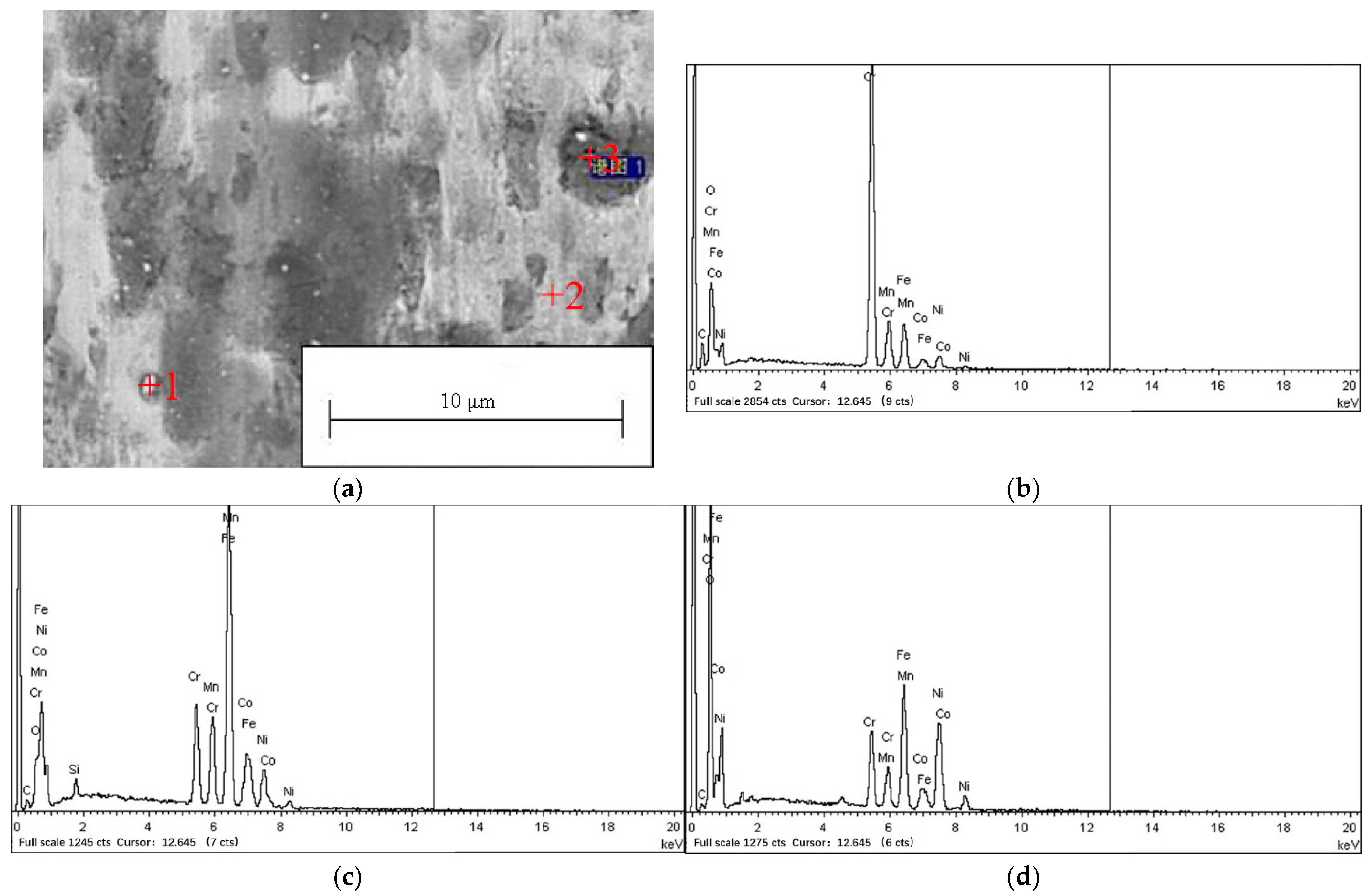
| Weight Percent/wt.% | O | C | Cr | Mn | Fe | Co | Ni | |
|---|---|---|---|---|---|---|---|---|
| Point | ||||||||
| Point 1 | 7.76 | 12.82 | 55.60 | 3.45 | 12.75 | 2.20 | 5.41 | |
| Point 2 | 3.78 | 4.53 | 10.44 | 11.62 | 49.59 | 8.79 | 10.24 | |
| Point 3 | 31.41 | 3.41 | 9.13 | 4.68 | 21.20 | 4.14 | 26.02 | |
Publisher’s Note: MDPI stays neutral with regard to jurisdictional claims in published maps and institutional affiliations. |
© 2022 by the authors. Licensee MDPI, Basel, Switzerland. This article is an open access article distributed under the terms and conditions of the Creative Commons Attribution (CC BY) license (https://creativecommons.org/licenses/by/4.0/).
Share and Cite
Gao, P.; Fu, R.; Liu, J.; Chen, B.; Zhang, B.; Zhao, D.; Yang, Z.; Guo, Y.; Liang, M.; Li, J.; et al. Influence of Plasma Arc Current on the Friction and Wear Properties of CoCrFeNiMn High Entropy Alloy Coatings Prepared on CGI through Plasma Transfer Arc Cladding. Coatings 2022, 12, 633. https://doi.org/10.3390/coatings12050633
Gao P, Fu R, Liu J, Chen B, Zhang B, Zhao D, Yang Z, Guo Y, Liang M, Li J, et al. Influence of Plasma Arc Current on the Friction and Wear Properties of CoCrFeNiMn High Entropy Alloy Coatings Prepared on CGI through Plasma Transfer Arc Cladding. Coatings. 2022; 12(5):633. https://doi.org/10.3390/coatings12050633
Chicago/Turabian StyleGao, Peihu, Ruitao Fu, Jilin Liu, Baiyang Chen, Bo Zhang, Daming Zhao, Zhong Yang, Yongchun Guo, Minxian Liang, Jianping Li, and et al. 2022. "Influence of Plasma Arc Current on the Friction and Wear Properties of CoCrFeNiMn High Entropy Alloy Coatings Prepared on CGI through Plasma Transfer Arc Cladding" Coatings 12, no. 5: 633. https://doi.org/10.3390/coatings12050633
APA StyleGao, P., Fu, R., Liu, J., Chen, B., Zhang, B., Zhao, D., Yang, Z., Guo, Y., Liang, M., Li, J., Wang, W., Yan, Z., & Zhang, L. (2022). Influence of Plasma Arc Current on the Friction and Wear Properties of CoCrFeNiMn High Entropy Alloy Coatings Prepared on CGI through Plasma Transfer Arc Cladding. Coatings, 12(5), 633. https://doi.org/10.3390/coatings12050633