Article

Tribological Properties of the 40Cr/GCr15 Tribo-Pair under Unidirectional Rotary and Reciprocating Dry Sliding

1
School of Materials Science and Engineering, Shanghai University, Shanghai 200444, China
2
State Key Laboratory of Advanced Special Steel, Shanghai University, Shanghai 200444, China
*
Author to whom correspondence should be addressed.
Coatings 2022, 12(5), 557; https://doi.org/10.3390/coatings12050557
Submission received: 24 March 2022 / Revised: 17 April 2022 / Accepted: 18 April 2022 / Published: 20 April 2022
(This article belongs to the Special Issue Microstructure, Fatigue and Wear Properties of Steels)

Abstract

:
The unidirectional rotary and reciprocating sliding experiments of the 40Cr pin/GCr15 disc tribo-pair were carried out on the MFT-5000 Rtec friction and wear tester under the same test conditions with a sliding speed of 0.2 m/s and a load of 150 N. Compared with reciprocating sliding, the tribo-pair in rotary sliding exhibits a stabler friction coefficient and better wear resistance. By analyzing the wear surface morphologies of the two pins, the main wear mechanism was found to be adhesive wear. For the tribo-layer of pin under reciprocating sliding, the surface microstructure plastically converges and forms a ridge from both sides to the middle, while a vortex structure is generated in the tribo-layer of pin under rotating sliding. The metamorphic structure and mircohardness of tribo-layer caused by the sliding forms are the key factors affecting the tribological properties.

1. Introduction

The friction and wear behavior of mechanical tribological pairs can be influenced by several variables, such as contact geometry, lubricant rheology and chemistry, relative motion, applied forces, the presence of third-bodies at the interface, temperature, stiffness and vibrations [1]. Parts operating in different sliding modes may be made of the same material. For example, 40Cr steel is commonly used to manufacture transmission shaft or piston parts. The metal-to-metal bearing combination in total hip arthroplasty [2,3] also has different sliding modes during its service process. Different sliding modes will inevitably lead to different tribological properties during its service, which is a field that needs in-depth research.
Plenty of studies have shown that the sliding modes affect the friction and wear properties in tribo-systems. Mussa et al. [4] reported that the motion form had significant influences on the wear volume and crack nucleation of the specimens in sliding contact. Han et al. [5] showed that the relative scuffing resistances of 1080 steel and grey cast iron were totally different with various sliding motions. Cho et al. [6,7] investigated the relationship between the sliding motion and the surface life against scuffing failure under lubricated conditions. Wu et al. [8] concluded that lubricant starvation caused by the piled-up of nano-MoS2 in unidirectional sliding impaired the lubrication performance, whereas reciprocating sliding improved the lubrication performance by forming net-like clusters with MoS2 nanoparticles. Balarini et al. [9] also detected that the presence of MoS2 tribo-film led to effective friction reduction only in tests with reciprocating motion. Liu et al. [10] suggested that the origin of the low friction of hydrogenated diamond-like carbon (H-DLC) films depended on unidirectional and reciprocating motions. Zhang et al. [11] compared the unidirectional and reciprocating sliding of a Cu–Al alloy and found that the reciprocating sliding was favorable for producing a morphologically vortical pattern and the DRX (dynamic recrystallization) structure, which rarely occurs under unidirectional sliding. In addition, the different types of sliding motion also have certain impacts on the friction and wear properties of coatings [12], nanoscale composites [13] and magnesium alloys [14].
Up till now, few comparative studies have been done about the influences of motion forms on the friction and wear behavior of structural steel under the same friction system. The general opinion is that the microstructural evolution and plastic deformation occurring in the sliding friction-induced deformation layer (tribo-layer) directly affect the friction and wear behaviors [15]. However, the early comparative studies [16,17,18,19] of different sliding motions of steels did not take into account the microstructural evolution and microhardness gradient in tribo-layers. As one of the most widely used friction pair materials in mechanical transmission components, the tribological behaviors of 40Cr steel were mainly investigated under unidirectional sliding conditions [20,21]. There are few studies on reciprocating the tribological behavior of 40Cr steel, especially the comparison of reciprocating and unidirectional sliding friction.
In the present work, the tribological behaviors of normalized 40Cr pin against hardened GCr15 disc/flat tribo-pair were studied using the MTF-5000 Rtec multifunctional tribometer on a reciprocating and rotary pin-on-disk contact in the same test conditions. The microstructural evolution in the tribo-layers with sliding mode is analyzed, so as to provide reference for the optimization of steel–steel friction pairs.

2. Materials and Experimental Methods

2.1. Sample Preparation

Commercial 40Cr steel and GCr15 steel with the chemical compositions listed in Table 1 were used as pin and disc/flat materials. The 40Cr pin had initial dimensions of Φ6 mm × 12 mm and hardness of 222 HBW after normalized at 850 °C. The GCr15 disc and flat had initial dimensions of Φ50 mm × 6 mm and 35 mm × 20 mm × 8 mm, respectively, and hardness of 60 HRC after oil quenching at 830 °C and tempering at 180 °C for 2 h. The surface roughness of the samples was 0.6 μm.

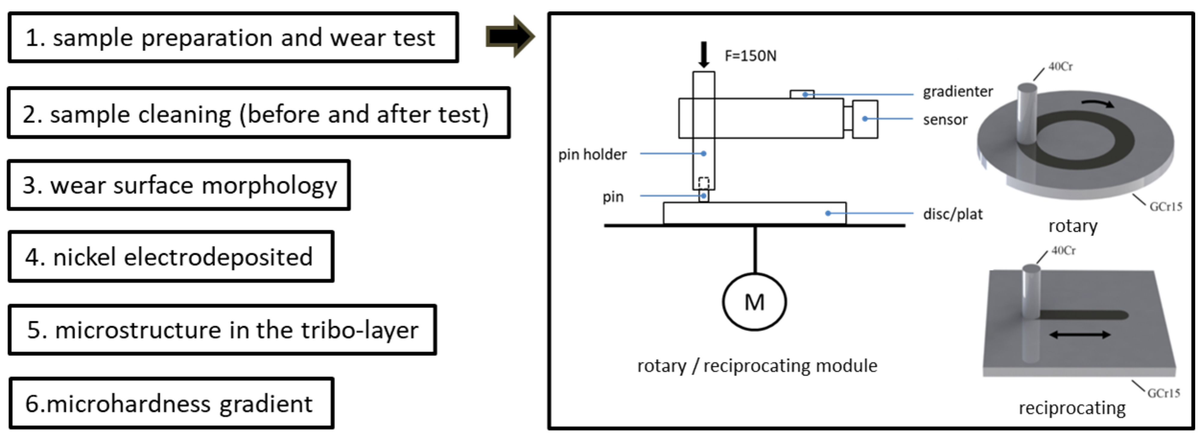
2.2. Wear Test and Characterization

The dry sliding wear test was carried out using a Rtec MTF-5000 multifunctional tribometer (Rtec instruments, San Jose, CA, USA) in a pin-on-flat contact in reciprocating and rotary configurations at room temperature in air. For reciprocating motion, a sliding stroke was 10 mm, and reciprocating frequency was 10 Hz (0.2 m/s sliding speed). To ensure the same sliding speed, rotary motion was carried out at 200 rpm with a gyration radius of 9.55 mm. The normal load was 150 N for two motion forms, and the nominal contact pressure was around 5.31 MPa. Wear tests were conducted at different friction durations in the range of 15 to 240 min. Before and after the experiment, the specimens were ultrasonically cleaned for 10 min in a mixture of acetone and ethanol. The testing results were averaged from three repeated tests. The mass loss of sample was determined by a G&G-JJ124BC precision electronic balance (G&G, Guangdong, China) with 0.1 mg resolution, and the corresponding wear rate was calculated by the equation: W = (E0 − E1)/T, where W is the wear rate (g/s), E0 is mass before test (g), E1 is mass after test (g) and T is sliding time (s). The experimental data are the averages of three repeated tests.
A Sigma-300 field emission scanning electron microscope (FE-SEM) (ZEISS, Oberkochen, Germany) was employed to observe the wear surfaces and cross-sectional morphologies of the pin specimens. After worn surface observation, the pin was nickel electrodeposited to protect the worn surface against damage and edging effect. The composition ratio of the plating solution is shown in Table 2. The plating current was 25 mA/cm2, and the plating time was 40 min.
The pins were cross-sectioned perpendicularly to the center of wear scar and parallel to the sliding direction, then inlayed using epoxy resin The center of the cross-sectional specimen was selected for observing the microstructure and measure microhardness of the tribo-layer. In addition, the pin specimens after reciprocating sliding were tested at quartile points along the sliding direction. These samples were prepared by grinding, mechanical polishing and electrolytic polishing.
The cross-sectioned microhardness of the tribo-layer of the pin was measured by a VH-1102 Vickers hardness tester (Buehler, Lake Bluff, IL, USA) under a 10 g load for 10 s. The transverse distance of two adjacent microhardness indentations was kept three times larger than the maximum diagonal to prevent interactions between consecutive measurements [22]. Each reported hardness value was the average of at least seven effective measured results.
Figure 1 summarizes the experimental flow and adds some details.

3. Results and Discussion

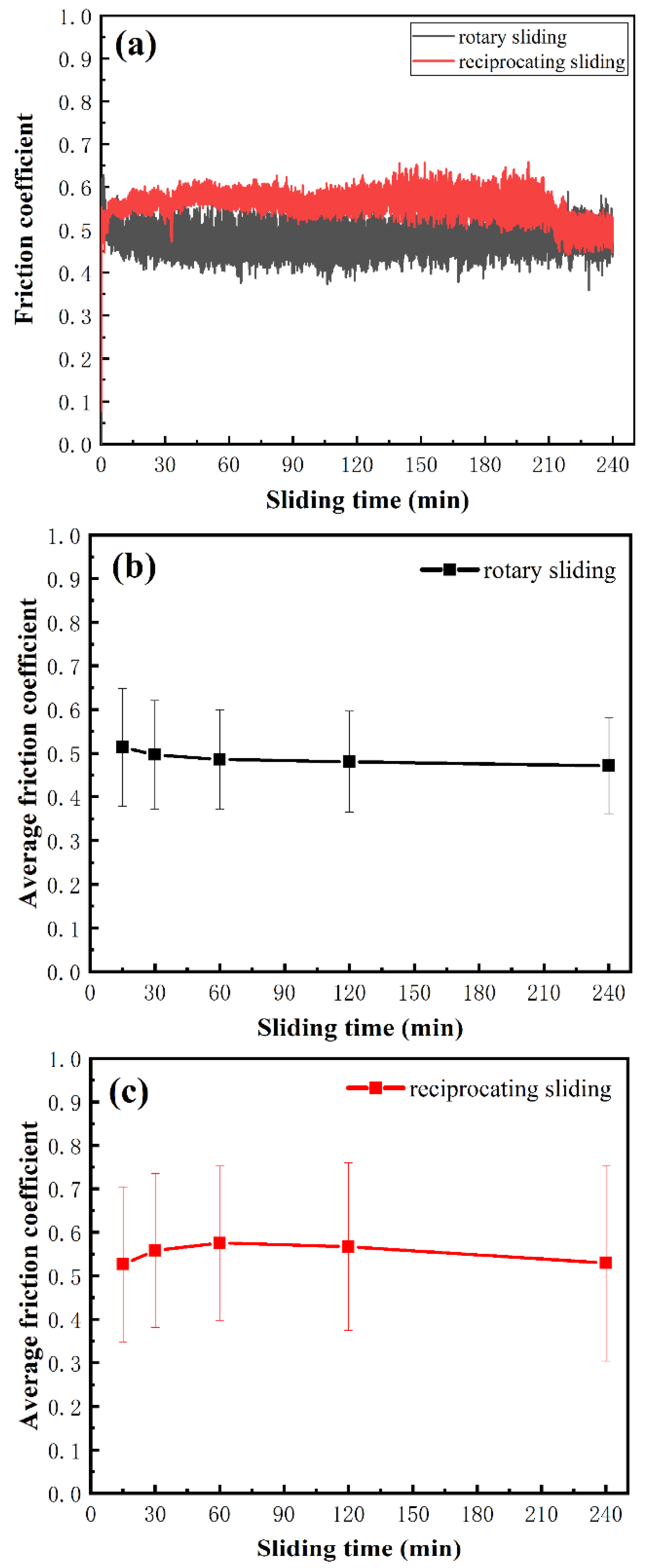
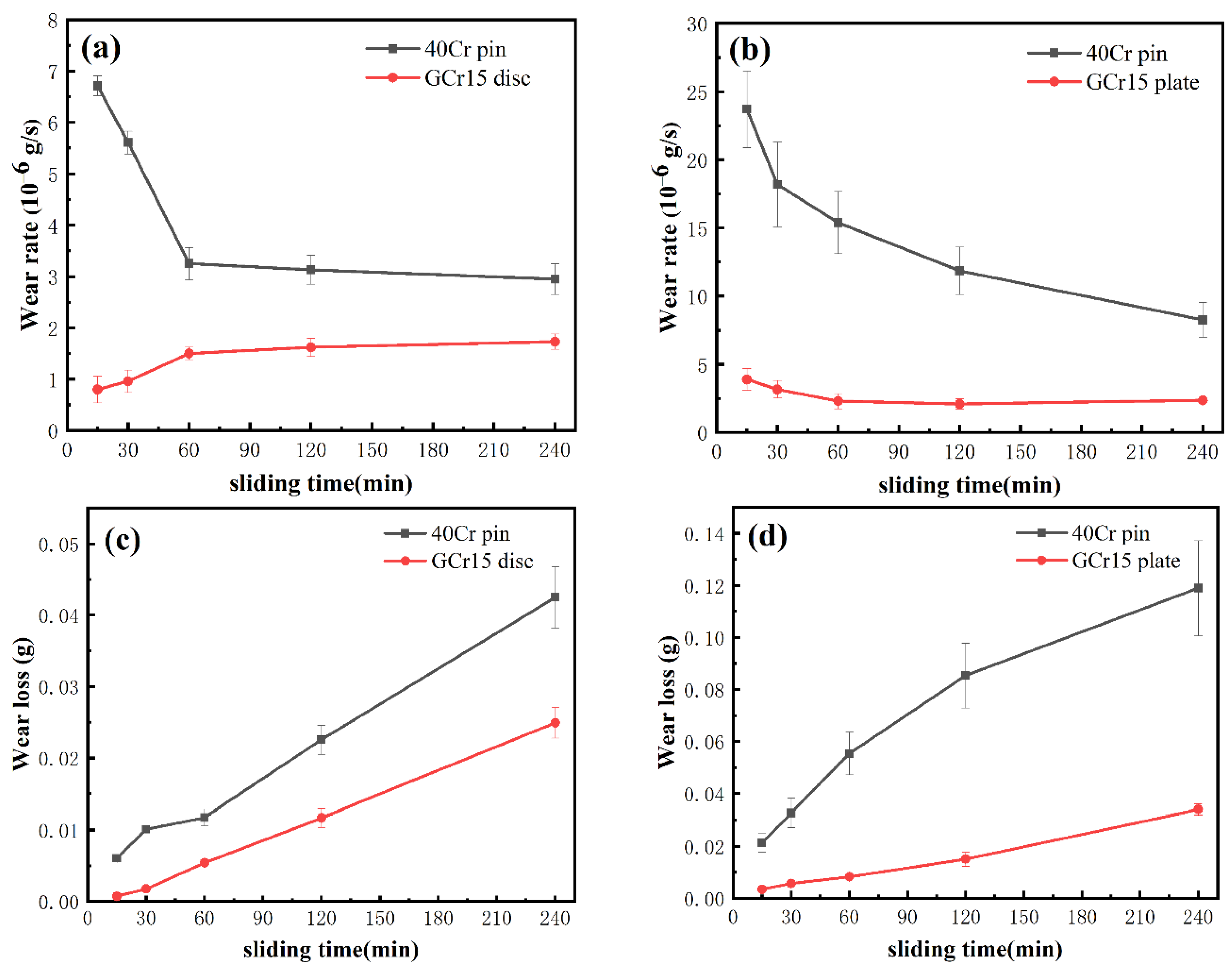
3.1. Tribological Performance

Figure 2 exhibits the friction coefficient (CoF) curves of normalized 40Cr pins and GCr15 specimens found via the rotary and reciprocating sliding. The error bars were obtained by calculating the standard deviation of the CoF, which can be used to characterize the degree of fluctuation of the CoF. The results showed that the CoF of reciprocating sliding is higher than that of rotating sliding. Compared with the rotary sliding with an error bar fluctuation range of 0.12, the CoF of reciprocating sliding was more unstable with an error bar fluctuation range of 0.2. For unidirectional sliding, Grützmacher et al. [23] suggested that the CoF curve showed some fluctuations due to the interaction of the presence of wear particles and the contact asperity, which was typical of frictional contacts with high contact ratios. As interfacial medium, debris may cause a larger friction coefficient and larger fluctuation under reciprocating sliding [10,18]. In addition, the stroke of reciprocating sliding is shorter than that of rotary sliding, and the heat dissipation is slower, which intensified the formation and propagation of surface microcracks and the detachment of debris from the matrix [24].
Figure 3 shows the changes in wear rates and mass loss with sliding time after rotary and reciprocating sliding tests. The mass loss measured in two different sliding modes show that the samples under unidirectional sliding exhibited higher wear resistance than those under reciprocating sliding, which is similar what was reported in [4,11]. Note that, although most of the wear debris disappeared after cleaning the sample, the debris was not completely ejected from the system as the third body in the interface [25]. It means that the wear rate and mass loss measured in this paper do not represent the actual material loss, but these data reflect the different stages and trends of wear and provide a certain reference for comparing the degree of material wear under the two motion forms. The formation, coalescence, and detachment from the sliding interface of wear particles greatly affected the friction and wear performance [18]. Therefore, the analysis of wear particles is further work that needs to be done.
The different trends of the wear rate from above tests indicated that the wear mechanism may have changed correspondingly. To explain the above phenomena and appreciate how the sliding modes affect the wear resistant, SEM observations of the worn surfaces of pin, flat and disc samples, and the cross-sectional morphologies of pin after different test durations were carried out. The microhardness along the depths ranging from the worn surface to the matrix for various distances was analyzed to discuss the wear mechanism and the possible reasons for different wear rates caused by sliding friction modes.

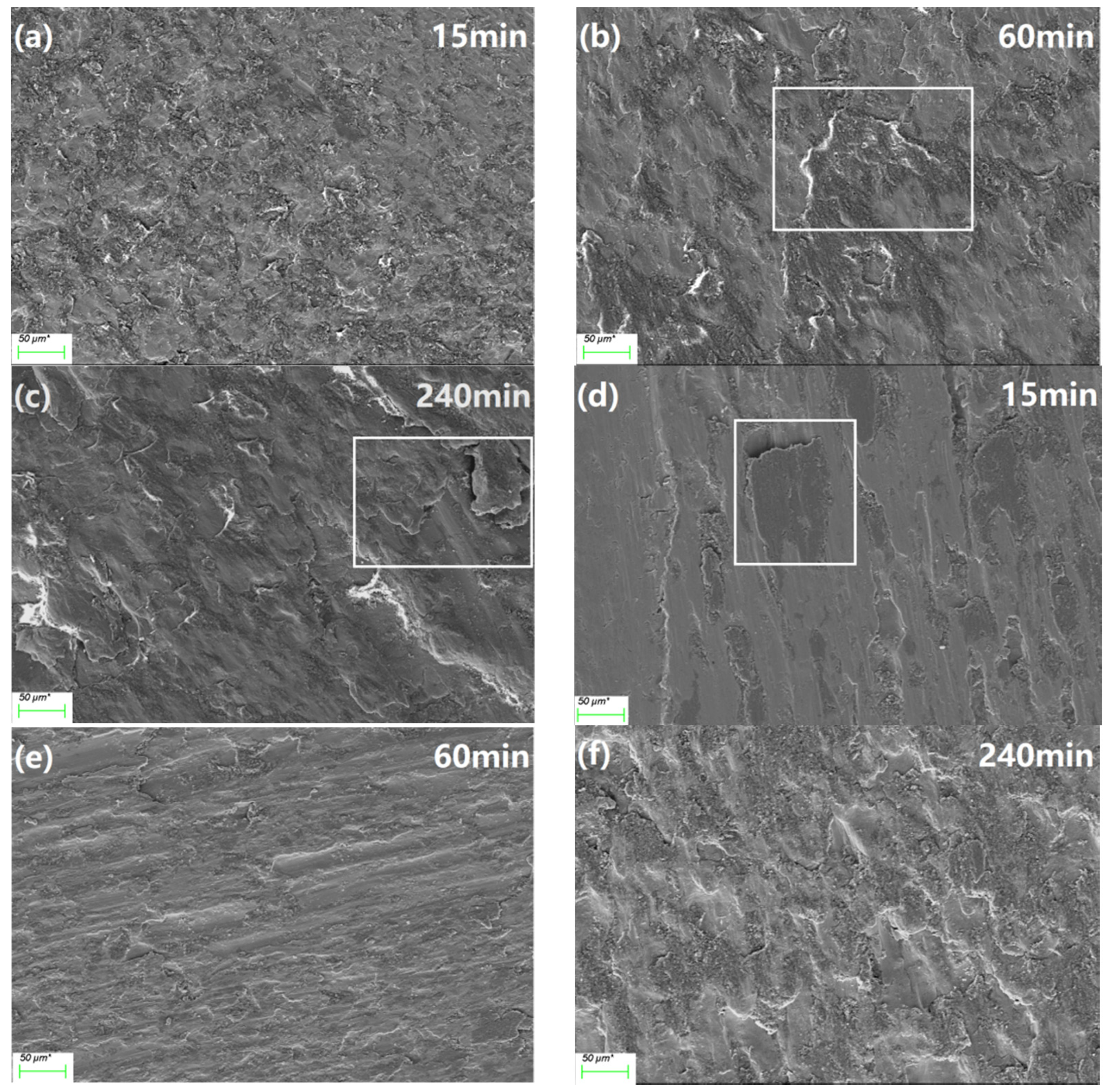
3.2. Wear Surface Morphology

3.2.1. Pin Samples

The dry sliding wear mechanism of pin sample under rotary sliding involved basically oxidation wear and adhesive wear. In the initial stage (Figure 4a), some porous initial oxide layer can be observed on the wear surface of pin sample. With the increase in sliding time, it was sintered and solidified under the action of friction heat; mixed and compacted with wear debris particles; and transformed into a larger black layer structure, as shown in Figure 4b, that may be the so-called mechanical mixing layer (MML) [26]. The studies [27,28] have testified that the hardness of MML is higher than that of the matrix material, which plays a protective role in the friction process as anti-friction layer. When the oxide film reaches the critical thickness, it becomes unstable and easy to peel off as wear debris due to its brittleness nature and the internal stress [5]. As shown in Figure 4c, the wear surface seriously peeled off and the groove became deeper.
For the reciprocating sliding, it can be seen in Figure 4d–f that the adhesive tracks on the wear surface are more severe and rougher. The oxide layer was sheared and squeezed to develop a cellular structure in both directions during sliding. Periodic bidirectional shear leads to a rougher surface, which is similar to the result in [4]. This also explains the results in Figure 2 and Figure 3. With the progress of wear and the action of reciprocating shear forces, the oxide layer was completely removed from the surface in the form of extrusion or delamination. The silver–white matrix material was revealed (Figure 4e). Additionally, the formed hard oxide debris, as abrasive particles ploughed the wear surface, aggravating the wear of tribo-pair, as shown in Figure 3. Additionally, the uneven wear surface of reciprocating sliding pin reflected more severe plastic deformation and sharp friction, as shown in Figure 2. The high temperature induced by friction heat softened the surface layer and then promoted the further plastic flow of tribo-layer [29].

3.2.2. Disc and Flat Samples

Figure 5 reveals the typical wear surfaces of disk and flat. The wear surface morphology after unidirectional rotating sliding was found to be very different from that after reciprocating sliding. For rotary sliding (Figure 5a–c), the main damage mechanisms are grooves running in the sliding direction and plastically deformed side ridges around the grooves, indicating that abrasive wear mainly took place at the initial stage. In the process of rotary sliding, the soft pin sample surface is prone to plastic deformation [30]; it softens and adheres to the friction plate surface with sliding time. Large pieces of protrusive material with dark grey could be observed on the wear surface, which distributed unevenly along the sliding direction, as shown in Figure 5c. They were assumed to be the products transferred from the pin surface due to plastic deformation and extrusion under the action of friction. After 60 min of rotary sliding, the grooves gradually decreased and the adhesion marks gradually increased in the worn surface of the disc specimen, which indicates that the adhesive wear gradually plays a dominant role as the main wear mechanism. The softer and more ductile pin metals tended to undergo more interlocking and hence agglomeration [18], and then transferred to the surface of the disc and formed a layered structure which peeled off from the disc substrate (Figure 5b,c). This is one of the reasons that the wear rate of the disc was much lower than that of the pin (Figure 3a).
For reciprocating sliding, it can be observed from the wear surfaces (Figure 5d–f) that they were much smoother and had fewer grooves. In addition, large clumps of adhesive material and oxide blocks were observed, indicating the main wear mechanisms were adhesive wear and oxidation wear. As shown in Figure 5d, there were small pits and black adhesive pits distributed on the wear surface of flat after 15 min sliding. The studies [17,18] have shown that compared with unidirectional motion, the reciprocating debris particles are smaller, and the possibility of debris remaining in the contact area increases. This was because the particles are easier to break when the motion or the direction of applied stress is reversed. With the progress of wear, the wear debris falling off during the wear process was repeatedly coated on the surface of the grinding plate under repeated compressive stress, resulting in a rough surface, as shown in Figure 5e. In Figure 5f, it can be observed that there are many oxide fragments on the wear surface of the plate, which are compacted debris and those adhesive transferred materials from the pin surface. They are subjected to back-and-forth shear stress and friction heat in the wear process, accumulated and compacted on the wear surface, causing more serious oxidation. This is the reason why the friction coefficient decreases (Figure 2) and the wear rate hardly increases after a long period of reciprocating sliding (Figure 3). The comparative analysis of the wear surfaces of the two sliding forms indicated that under reciprocating sliding conditions, more attention should be paid to the improvement of the anti-adhesive wear performance of the disc.

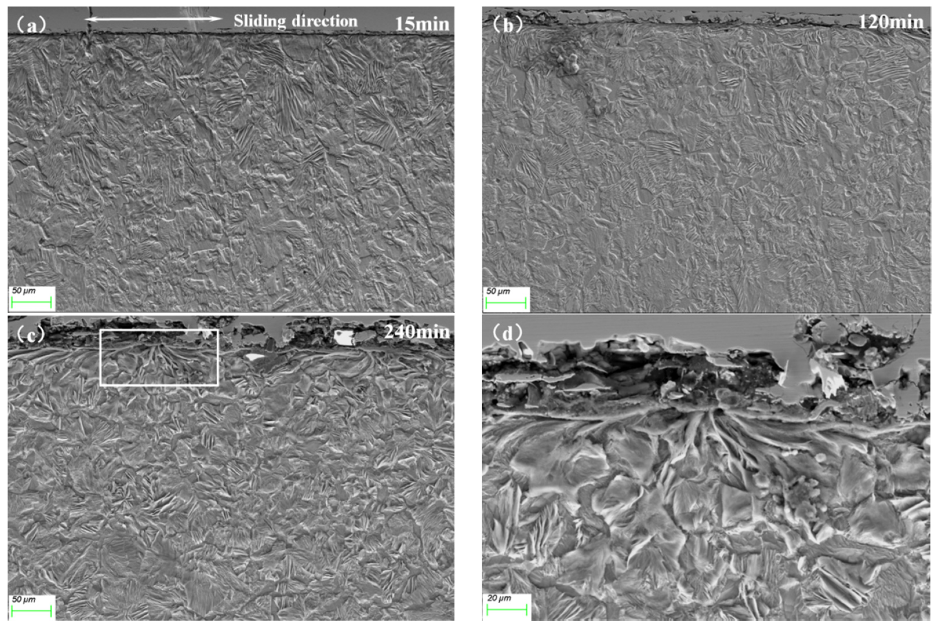
3.3. Microstructural Evolution in the Tribo-Layer

3.3.1. Rotary Sliding

Figure 6 displays the cross-sectional microstructure in the central area of the rotary sliding pin under different sliding durations. The plastic deformation intensified with the extended testing duration, which revealed obvious plastic flow along the sliding direction in the near surface area. As reported in [27], structurally, such a distinct area could be divided into different zones as follows (the outer layer is a protective Ni coating):
(I) The mechanical mixing layer (MML). A large amount of pearlite in this layer was deformed and broken, and there was an obvious gap in the local area. During the process of repeated cyclic friction, flake pearlite on the surface was plastically deformed along the sliding direction under the action of normal stress and shear stress. However, due to its brittleness nature, it was easy to break and expand along the ferrite with low hardness and formed pores.
(II) The plastic deformation layer (PDL). The plastic flow line along the sliding direction can be observed, and the deformation degree gradually decreased from the worn surface to the matrix. The severe plastic deformation induced by sliding friction caused abundant defects, such as dislocations and vacancies, which had a great influence on the grain refinement and strain hardening behavior of materials during friction.
After the sliding duration of 15 min, as shown in Figure 6a, the microstructure of the sub-surface layer absorbed a certain amount of friction energy, resulting in discontinuity and partial fracturing of the structure [31]. With the increase in wear time, as shown in Figure 6b, it can be observed that the protective MML layer thickened, which reduced the wear rate of pin samples (Figure 3a). At this time, the laminar flow between pearlite and ferrite on the surface of the deformation layer was destroyed and mixed near the surface, which formed a vortex structure. Our previous study [21] reported a similar vortex structure, which was caused by uneven local stress distribution, and sub-surface observations revealed a nanocrystalline structure. Due to the local high strain [32] and shear instability [33,34] during frictional wear, the dislocation continued to accumulate with the deformation process and gradually formed sub-structures with high densities of defects, until the original gradient structure formed fragments and particle aggregates of different scales [35]. Such sub-structural fragments underwent translational and rotational deformation along the sliding direction [36], eventually forming a discontinuous, vortex structure with a radius depending on the thickness of the fragmentation layer in a local area under a certain depth from the wear surface (Figure 6b). It should be noted that due to the structural incompatibility between the crushed material and the surrounding nanocrystalline layers [36], the presence of defects such as voids and cracks could be clearly observed at the boundaries of the turbulent-like structure, such as the large number of cracks between the MML layer and the vortex structure in Figure 6d. The main features of this generated turbulent-like structure are the accumulation of severe plastic deformation and the high degree of grain refinement, and we measured the microhardness of this structure, which will be discussed in Section 3.4.

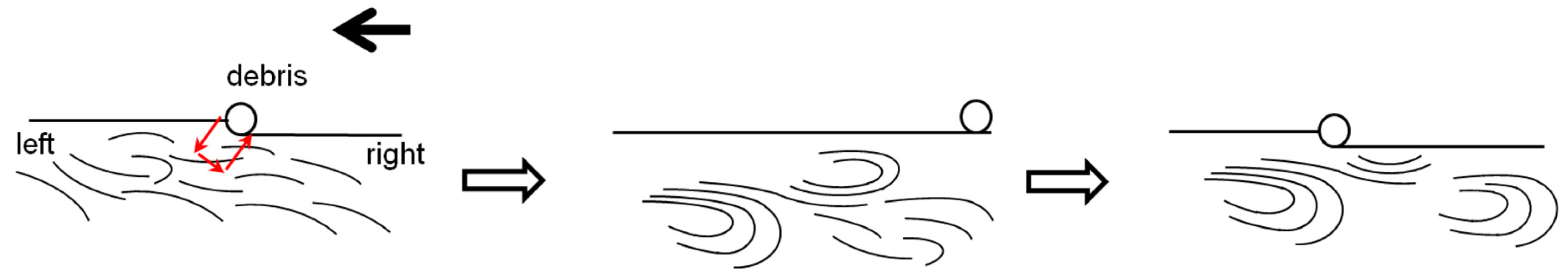
3.3.2. Reciprocating Sliding

Figure 7 displays the cross-sectional microstructure in the central area of the reciprocating sliding pin under different sliding durations. No obvious MML layer or PDL layer was observed in a short test period (Figure 7a), and the wear surface was relatively flat. The fatigue failure caused by bidirectional shear force during reciprocating sliding may be the reason that why MML layer was difficult to form. In addition, although the sliding speed was consistent, the smaller motion trajectory under reciprocating sliding accelerated the accumulation of friction heat, which made it difficult to form MML [37]. The wear rate of the pin specimen under unidirectional rotational sliding was much lower than that under reciprocating sliding (Figure 3), which indicated that the formation of the MML layer was beneficial for reducing the wear rate.
It is noteworthy to mention that no vortex structure like that of a unidirectional sliding pin (Figure 6) was found in the cross-sections of reciprocating sliding pins after extensive tests. Differently, Zhang et al. [11] found that the reciprocating motion facilitated the generation of vortex structures in nanostructured copper. Grützmacher et al. [38] reported the vortex-like nanostructures under reciprocating sliding. On the one hand, reciprocating sliding sheared in both directions with opposite strains, so one possible reason for the structures is that strain rates are insufficient to produce a nanocrystalline structure, such as a nanostructured mixed layer (NML). This substructure provided enough inhomogeneity to allow shear instability, offering conditions for the creation of vortex structures [39]. The reports on the vortex structure of steel materials focused on unidirectional sliding [21,35]. Of course, this speculation requires sufficient experiments or computational analysis to verify. On the other hand, related experiments have shown that the vortex structures tended to occur in FCC metals or their alloys with low stacking fault energies [11,30,31,32]. These softer metals are characterized by the rapid accumulation of dislocations in the early stages of strain, reducing their energy by adapting to low-angle subgrain boundaries. After further deformation, the subcrystal diameter decreased and the difference in subcrystal orientation increased, leading to the appearance of large-angle grain boundaries [31]. Zhang et al. [11] found that the reciprocating motion facilitated the generation of vortex structures in nanostructured copper. The recrystallization of low stacking fault energies materials during wear would dominate the surface and sub-surface structural evolution patterns [40], contributing to the formation of nanocrystals [41], when vorticity resulting from shear instability may more readily drive mechanical mixing and the formation of NML-like structures [42]. In summary, compared to the nanostructured copper reported by [11], BCC-structured steel materials under reciprocating sliding would have difficulties in forming vortex structures. In addition, the alloying element addition [35,43] had an effect on the formation of the vortex structure by changing the plastic deformation mechanism or by suppressing the grain boundary migration rate. Therefore, it is also important to consider the adjustments in alloy composition or initial microstructure under different friction systems.
An interesting phenomenon can be observed in Figure 7b,c: the tissue on both sides was biased towards the central region. To further observe this phenomenon, Figure 8 shows the cross-sectional microstructure of each region after 120 min of reciprocating sliding. The PDL depth increased gradually, and the deformation flow line was gradually apparent from the center of the pin to its edge, which implied that the outer layer of the pin underwent greater plastic deformation and work hardening. Furthermore, it can also be found in Figure 8a,b,d,e that the outer microstructure of the pin showed that the edge flowed to the middle due to the shear force in the opposite direction during reciprocating sliding. In addition, the analysis on the cross-sectional microstructure of the pin after different reciprocating sliding duration showed that the flow line in the outer layer bended and aggregated towards the center regardless of the test duration. The longer the test lasted or the longer the pin slid, the more pronounced this phenomenon became (Figure 7).

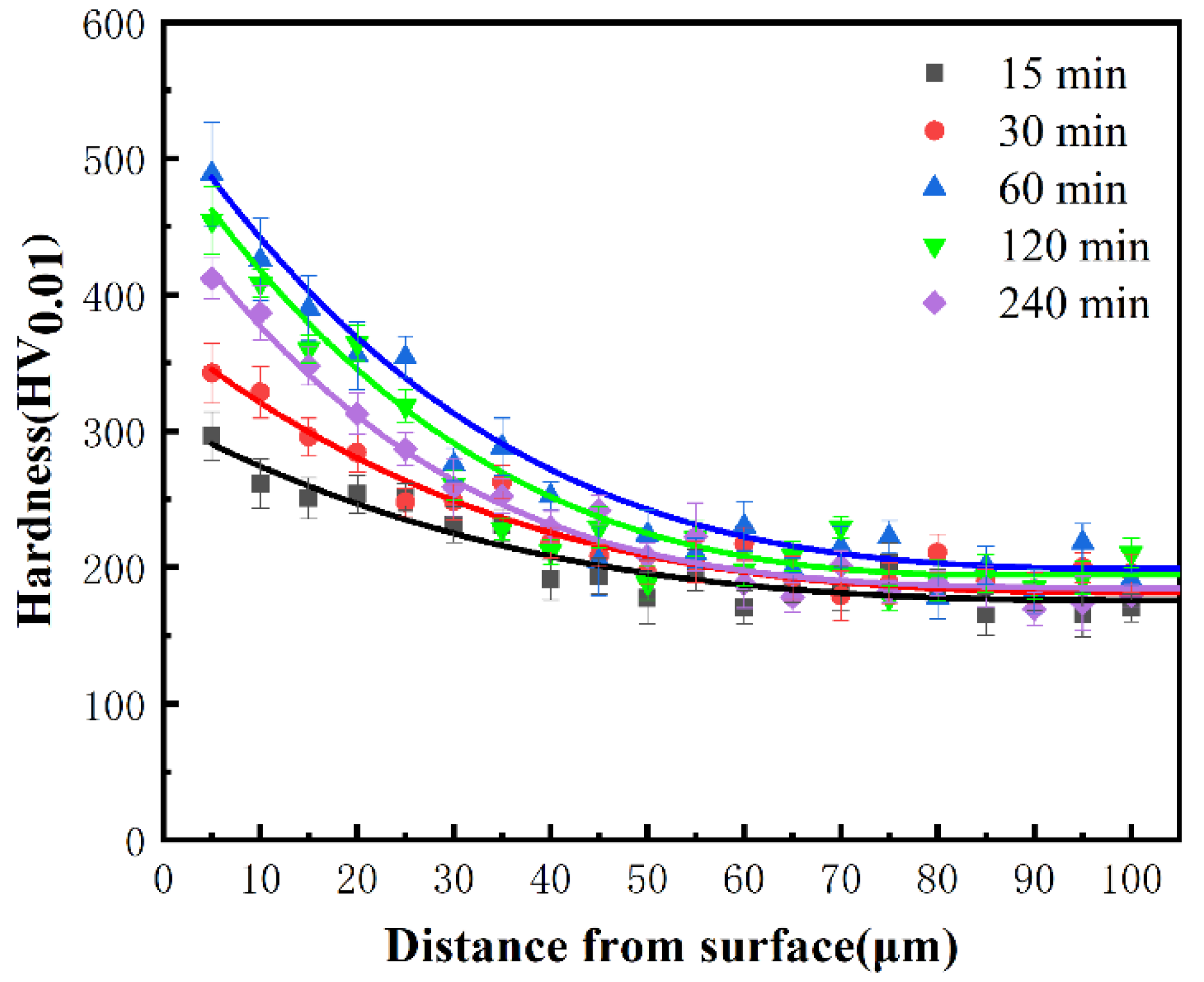
3.4. Microhardness Gradient

Figure 9 illustrates the variations in microhardness throughout the depth from the worn surface to the matrix after sliding for various durations under rotary sliding. The highest hardness appeared in the outermost area. The cross-sectional hardness gradually decreased from the surface to the matrix. It is not difficult to find that this trend was consistent with the microstructural evolution in the sub-surface layer, as shown in Figure 6. The outmost layer region exhibited higher microhardness after 60 min sliding, which is consistent with the trend of reducing wear rate in the pin samples in Figure 3 and the massive oxide on the wear surface in the Figure 4b. Rosenkranz et al. [44] reported that enlarged surface oxidation can lead to a significant increase in hardness and thus reduce wear, which was confirmed by our experimental results. At this time, many vortex structures generated at the outer surface. The microhardness values near this region increased steeply, exhibiting a relatively high microhardness of 489 HV0.01, which was similar to the results shown in [34]. Unfortunately, none of the studies [31,32,33] have carried out hardness characterization of the vortex structure. In addition, the formed structure and surrounding microstructures can be further analyzed by nanoindentation technology, which is the work we need to carry out in the future.
Our previous study [21] confirmed that the vortex structure was mainly composed of nanocrystals caused by severe plastic deformation, forming hardened areas near the wear surface. As shown in Figure 6d, after 120 min of sliding, the vortex structure boundary was prone to forming cracks and peel off at the boundary. Concurrently, the plastic toughness of the surface material could not effectively absorb friction energy through plastic deformation, through the formation and expansion of cracks and brittle hard abrasive chips from the parent matrix to absorb and dissipate friction energy. The surface material gradually lost its strain hardenability. The tissue of this layer was gradually extruded from the surface of the plastic deformation layer during the wear process [45]; i.e., its plastic deformability decayed. At the same time, the tissue at the bottom of the vortex layer continued to transform into a vortex structure under shear (Figure 10); i.e., the vortex structure underwent a cyclic process of stripping and regrowth during steady state, during which a large number of fragmentation products were carried away from the tribo-layer. In return, an imminent stripped layer formed, and the wear rate increased [21].
The microhardnesses of different sliding modes were also compared in the report [4], but the hardnesses of different positions under reciprocating sliding was ignored. In Figure 11, microhardness curves are plotted according to the location of each region in Figure 8f. The results show a gradual decrease in microhardness from the edge region to the center region, a trend consistent with the degree of plastic deformation in the cross-sectional organization of Figure 8. The smaller and more uneven oxide layers (Figure 7 and Figure 8) under reciprocating sliding may be responsible for this trend [27,28]. Besides, unlike unidirectional rotational sliding, shearing in both directions under reciprocating sliding led to an inconsistent direction of plastic deformation, with plastic flow on one side weakening plastic deformation in the opposite direction. This offset was most evident in the central region: the direction of deformation changed at a location in the middle. The lower hardness in the intermediate region also increased the actual contact area, raised the incidence of adhesion [46], accelerated the flaking of abrasive chips and led to a much higher wear rate of the pin sample under reciprocating sliding than under rotary sliding, as in Figure 3.
Those results suggest that the sliding mode significantly influenced the response of the tribo-layer’s microstructure and the hardness gradient. It can provide some reference value for the optimization of steel–steel tribo-pair, although it is not comprehensive enough. More investigation is worth doing for different debris sizes and morphologies, along with finite element analysis of the contact pressure and mechanism analysis at the dislocation level.

4. Conclusions

Based the comparative study of the tribological properties of the 40Cr/GCr15 tribo-pair under unidirectional rotary and reciprocating sliding tests, the following conclusions can be drawn: The 40Cr/GCr15 tribo-pair under unidirectional sliding exhibited higher wear resistance than under reciprocating sliding. The wear mechanisms of the pin sample under rotary sliding involved mainly oxidation wear and adhesive wear, whereas the wear mechanism of the pin sample under reciprocating sliding involved mainly severe adhesive wear. The sliding mode significantly influenced the response of the tribo-layer’s microstructure and the hardness gradient. For reciprocating sliding, the microstructural plastic flow of the tribo-layer converged from the edge to the center area, and the PDL thickness decreased from the edge area to the center area. This trend was consistent with the measured hardness in the tribo-layer. Under unidirectional rotary sliding, the severely deformed vortex structure with high microhardness and brittleness was formed in the tribo-layer. The reason for the difficulty in forming the vortex structure in reciprocating sliding may have been the relatively high stacking fault energy and insufficient strain rate. Therefore, it is necessary to perform further study at the dislocation level and finite element simulations. These are underway.

Author Contributions

Conceptualization, J.C., H.T., W.W., X.W. and H.Z.; methodology, J.C., H.T., W.W., X.W. and H.Z.; investigation and formal analysis, J.C., H.T., W.W., X.W. and H.Z.; writing—original draft preparation, J.C., H.T., W.W., X.W. and H.Z.; writing—review and editing, J.C., H.T., W.W., X.W. and H.Z. All authors have read and agreed to the published version of the manuscript.

Funding

The work was supported by the National Natural Science Foundation of China (Grant No. 52031004).

Institutional Review Board Statement

Not applicable.

Informed Consent Statement

Not applicable.

Data Availability Statement

The data presented in this study are available on request from the corresponding author.

Acknowledgments

The authors also wished to thank Xiaofei Guo for her valuable advice in the paper.

Conflicts of Interest

The authors declare no conflict of interest.

References

  1. Blau, P. The significance and use of the friction coefficient. Tribol. Int. 2001, 34, 585–591. [Google Scholar] [CrossRef]
  2. Jamari, J.; Ammarullah, M.I.; Saad, A.P.M.; Syahrom, A.; Uddin, M.; van der Heide, E.; Basri, H. The Effect of Bottom Profile Dimples on the Femoral Head on Wear in Metal-on-Metal Total Hip Arthroplasty. J. Funct. Biomater. 2021, 12, 38. [Google Scholar] [CrossRef] [PubMed]
  3. Ammarullah, M.I.; Afif, I.Y.; Maula, M.I.; Winarni, T.I.; Tauviqirrahman, M.; Akbar, I.; Basri, H.; van der Heide, E.; Jamari, J. Tresca Stress Simulation of Metal-on-Metal Total Hip Arthroplasty during Normal Walking Activity. Materials 2021, 14, 7554. [Google Scholar] [CrossRef] [PubMed]
  4. Mussa, A.; Krakhmalev, P.; Bergström, J. Sliding wear and fatigue cracking damage mechanisms in reciprocal and unidirectional sliding of high-strength steels in dry contact. Wear 2020, 444–445, 203119. [Google Scholar] [CrossRef]
  5. Han, J.M.; Zhang, R.; Ajayi, O.O.; Barber, G.C.; Zou, Q.; Guessous, L.; Schall, D.; Alnabulsi, S. Scuffing behavior of gray iron and 1080 steel in reciprocating and rotational sliding. Wear 2010, 271, 1854–1861. [Google Scholar] [CrossRef]
  6. Cho, D.H.; Lee, Y.Z. Comparison of scuffing life between unidirectional and reciprocating sliding motion. Wear 2011, 271, 1637–1641. [Google Scholar] [CrossRef]
  7. Cho, D.H.; Kim, J.S.; Jia, J.; Lee, Y.Z. Comparative analysis based on adiabatic shear instability for scuffing failure between unidirectional and reciprocating sliding motion. Wear 2013, 297, 774–780. [Google Scholar] [CrossRef]
  8. Wu, H.; Li, X.; He, X.; Lu, J.; Wang, L.; Zhou, B.; Dong, G. An investigation on the lubrication mechanism of MoS2 nanoparticles in unidirectional and reciprocating sliding point contact: The flow pattern effect around contact area. Tribol. Int. 2018, 122, 38–45. [Google Scholar] [CrossRef]
  9. Balarini, R.; Diniz, G.A.S.; Profito, F.J.; Souza, R.M. Comparison of unidirectional and reciprocating tribometers in tests with MoDTC-containing oils under boundary lubrication. Tribol. Int. 2019, 149, 105686. [Google Scholar] [CrossRef]
  10. Liu, Y.; Chen, L.; Jiang, B.; Liu, Y.; Zhang, B.; Xiao, C.; Zhang, J.; Qian, L. Origin of low friction in hydrogenated diamond-like carbon films due to graphene nanoscroll formation depending on sliding mode: Unidirection and reciprocation. Carbon 2020, 173, 696–704. [Google Scholar] [CrossRef]
  11. Zhang, Q.; Chen, X.; Han, Z. Subsurface morphological pattern, microstructure and wear response of Cu and Cu–Al alloys subjected to unidirectional and reciprocating sliding. Wear 2020, 462–463, 2023521. [Google Scholar] [CrossRef]
  12. Podgornik, B.; Vizintin, J.; Ronkainen, H.; Holmberg, K. Friction and wear properties of DLC-coated plasma nitrided steel in unidirectional and reciprocating sliding. Thin Solid Film. 2000, 377, 254–260. [Google Scholar] [CrossRef]
  13. Jumahat, A.; Talib, A.A.A.; Sharudin, H.; Zulfikli, N.W.M. Tribological behavior of nanoclay-filled basalt fiber-reinforced polymer composites. In Tribology of Polymer Composites; Elsevier: Amsterdam, The Netherlands, 2021; pp. 143–162. [Google Scholar]
  14. Blau, P.; Walukas, M. Sliding friction and wear of magnesium alloy AZ91D produced by two different methods. Tribol. Int. 2000, 33, 573–579. [Google Scholar] [CrossRef]
  15. Rigney, D.A.; Divakar, R.; Kuo, S.M. Deformation substructures associated with very large plastic strains. Scr. Metall. Mater. 1992, 27, 975–980. [Google Scholar] [CrossRef]
  16. Ward, R. A comparison of reciprocating and continuous sliding wear. Wear 1970, 15, 423–434. [Google Scholar] [CrossRef]
  17. Noboru, Y.; Fusao, H. A Comparison of Wear of Annealed Carbon Steels between Reciprocating Friction and Uni-Directional Friction under Lubrication. Trans. Jpn. Soc. Mech. Eng. Ser. C 1981, 47, 1354–1365. [Google Scholar]
  18. Hwang, D.H.; Kim, D.E.; Lee, S.J. Influence of wear particle interaction in the sliding interface on friction of metals. Wear 1999, 225–229, 427–439. [Google Scholar] [CrossRef]
  19. Marui, E.; Endo, H. Effect of reciprocating and unidirectional sliding motion on the friction and wear of copper on steel. Wear 2001, 249, 582–591. [Google Scholar] [CrossRef]
  20. Zhao, X.; Zhao, B.; Liu, Y.; Cai, Y.; Hu, C. Research on friction and wear behavior of gradient nano-structured 40Cr steel induced by high frequency impacting and rolling. Eng. Fail. Anal. 2017, 83, 167–177. [Google Scholar] [CrossRef]
  21. Liang, S.; Zhu, P.; Yang, Y.; He, X.; Wei, X. Subsurface Dynamic Deformation and Nano-structural Evolution in 40Cr Steel Under Dry Sliding Wear. Tribol. Lett. 2019, 67, 102. [Google Scholar] [CrossRef]
  22. Chromik, R.R.; Zhang, Y. Nanomechanical testing of third bodies. Curr. Opin. Solid State Mater. Sci. 2018, 22, 144–155. [Google Scholar] [CrossRef]
  23. Grützmacher, P.G.; Rosenkranz, A.; Rammacher, S.; Gachot, C.; Mücklich, F. The influence of centrifugal forces on friction and wear in rotational sliding. Tribol. Int. 2017, 116, 256–263. [Google Scholar] [CrossRef]
  24. So, H. Characteristics of wear results tested by pin-on-disc at moderate to high speeds. Tribol. Int. 1996, 29, 415–423. [Google Scholar] [CrossRef]
  25. Fillot, N.; Iordanoff, I.; Berthier, Y. Wear modeling and the third body concept. Wear 2007, 262, 949–957. [Google Scholar] [CrossRef]
  26. Young, J.L.; Wilsdorf, K.D.; Hull, R. The generation of mechanically mixed layers (MMLs) during sliding contact and the effects of lubricant thereon. Wear 2000, 246, 74–90. [Google Scholar] [CrossRef]
  27. Venkataraman, B.; Sundararajan, G. Correlation between the characteristics of the mechanically mixed layer and wear behaviour of aluminium, Al-7075 alloy and Al-MMCs. Wear 2000, 245, 22–38. [Google Scholar] [CrossRef]
  28. Ghazali, M.J.; Rainforth, W.M.; Omar, M.Z. A comparative study of mechanically mixed layers (MMLs) characteristics of commercial aluminium alloys sliding against alumina and steel sliders. J. Mater. Processing Technol. 2008, 201, 662–668. [Google Scholar] [CrossRef]
  29. Alsaran, A. Determination of tribological properties of ion-nitrided AISI 5140 steel. Mater. Charact. 2002, 49, 171–176. [Google Scholar] [CrossRef]
  30. Viáfara, C.C.; Sinatora, A. Influence of hardness of the harder body on wear regime transition in a sliding pair of steels. Wear 2009, 267, 425–432. [Google Scholar] [CrossRef]
  31. Kolubaev, A.; Tarasov, S.; Sizova, O.; Kolubaev, E. Scale-dependent subsurface deformation of metallic materials in sliding. Tribol. Int. 2010, 43, 695–699. [Google Scholar] [CrossRef]
  32. Schouwenaars, R.; Jacobo, V.H.; Ortiz, A. Microstructural aspects of wear in soft tribological alloys. Wear 2007, 263, 727–735. [Google Scholar] [CrossRef]
  33. Tarasov, S.; Rubtsov, V.; Kolubaev, A. Subsurface shear instability and nanostructuring of metals in sliding. Wear 2010, 268, 59–66. [Google Scholar] [CrossRef]
  34. Yao, B.; Han, Z.; Li, Y.S.; Tao, N.R.; Lu, K. Dry sliding tribological properties of nanostructured copper subjected to dynamic plastic deformation. Wear 2011, 271, 1609–1616. [Google Scholar] [CrossRef]
  35. Sharkeev, Y.P.; Legostaeva, E.V.; Panin, S.V.; Gritsenko, B.P. Experimental investigation of friction and wear of Mo ion implanted ferritic/pearlitic steel. Surf. Coat. Technol. 2002, 158, 674–679. [Google Scholar] [CrossRef]
  36. Panin, V.; Kolubaev, A.; Tarasov, S.; Popov, V. Subsurface layer formation during sliding friction. Wear 2001, 249, 860–867. [Google Scholar] [CrossRef]
  37. Zhu, J.; Ma, L.; Joyce, R.S. Friction and wear of Cu-15wt%Ni-8wt%Sn bronze lubricated by grease at room and elevated temperature. Wear 2020, 460–461, 203474. [Google Scholar] [CrossRef]
  38. Grützmacher, P.G.; Suarez, S.; Tolosa, A.; Gachot, C.; Song, G.; Wang, B.; Presser, V.; Mücklich, F.; Anasori, B.; Rosenkranz, A. Superior Wear-Resistance of Ti3C2Tx Multilayer Coatings. ACS Nano 2021, 15, 8216–8224. [Google Scholar] [CrossRef]
  39. Rigney, D.A. Transfer, mixing and associated chemical and mechanical processes during the sliding of ductile materials. Wear 2000, 245, 1–9. [Google Scholar] [CrossRef]
  40. Bill, R.C.; Wisander, D. Recrystallization as a controlling process in the wear of some F.C.C. metals. Wear 1977, 41, 351–363. [Google Scholar] [CrossRef]
  41. Karthikeyan, S.; Agrawal, A.; Rigney, D.A. Molecular dynamics simulations of sliding in an Fe–Cu tribopair system. Wear 2009, 267, 1166–1176. [Google Scholar] [CrossRef]
  42. Rigney, D.A.; Karthikeyan, S. The Evolution of Tribomaterial during Sliding: A Brief Introduction. Tribol. Lett. 2010, 39, 3–7. [Google Scholar] [CrossRef]
  43. Chen, X.; Han, Z.; Lu, K. Wear mechanism transition dominated by subsurface recrystallization structure in Cu-Al alloys. Wear 2014, 320, 41–50. [Google Scholar] [CrossRef]
  44. Rosenkranz, A.; Heib, T.; Gachot, C.; Mücklich, F. Oil film lifetime and wear particle analysis of laser-patterned stainless steel surfaces. Wear 2015, 334, 1–12. [Google Scholar] [CrossRef]
  45. Psakhie, S.G.; Zolnikov, K.P.; Dmitriev, A.I.; Smolin, A.Y.; Shilko, E.V. Dynamic vortex defects in deformed material. Phys. Mesomech. 2014, 17, 15–22. [Google Scholar] [CrossRef]
  46. Li, C.; Bell, T. Sliding wear properties of active screen plasma nitrided 316 austenitic stainless steel. Wear 2004, 256, 1144–1152. [Google Scholar] [CrossRef]
Figure 1. Schematic diagram of workflow of experimental test.
Coatings 12 00557 g001
Figure 2. The variation of friction coefficient with the sliding time under rotary sliding and reciprocating sliding modes (a); the average friction coefficient with error bars for rotary sliding (b) and reciprocating sliding (c).
Coatings 12 00557 g002
Figure 3. The variation in wear rate with the sliding time under rotary (a) and reciprocating sliding (b); the average mass loss of the pins under rotary (c) and reciprocating sliding (d).
Coatings 12 00557 g003
Figure 4. Surface morphology of pin sample in rotary (ac) and reciprocating sliding (df) under different sliding durations.
Coatings 12 00557 g004
Figure 5. Surface morphology of GCr15 disc or flat after rotary (ac) and reciprocating sliding (df) for different sliding durations.
Coatings 12 00557 g005
Figure 6. Cross-sectional microstructures of 40Cr pins after rotary sliding: (a) 15 min, (b) 120 min, (c) 240 min, (d) the magnified region in (b).
Coatings 12 00557 g006
Figure 7. Cross-sectional microstructures of 40Cr pins after reciprocating sliding: (a) 15 min, (b) 120 min, (c) 240 min, (d) the magnified region in (c).
Coatings 12 00557 g007
Figure 8. Cross-sectional microstructures of 40Cr pin after reciprocating 120 min sliding: (a) left edge area, (b) left quarter area, (c) central area, (d) right quarter area, (e) right edge area, (f) the sketch of the location of each quartering point.
Coatings 12 00557 g008
Figure 9. Microhardness changes below the central area of 40Cr pin wear surface after different sliding distances under rotary sliding.
Coatings 12 00557 g009
Figure 10. Schematic diagram of the development of the vortex structure.
Coatings 12 00557 g010
Figure 11. Microhardness changes in different areas of 40Cr pin wear surface and different depths below the surface under reciprocating sliding duration of: (a) 15 min; (b) 120 min; the abscissa represents each area in Figure 8f.
Coatings 12 00557 g011
Table 1. Chemical compositions of 40Cr and GCr15 steels (wt.%).
MaterialCCrMnSiNiSPFe
40Cr0.4340.8930.6440.2420.0260.0070.014Balance
GCr151.0101.4790.3150.2180.0220.0080.021Balance
Table 2. Composition of the electroplating nickel bath.
CompositionNiSO4·7H2ONiCl2H3BO3NaC12H25SO4
Content320 g /L45 g/L30 g/L0.5 g/L
Publisher’s Note: MDPI stays neutral with regard to jurisdictional claims in published maps and institutional affiliations.

