Article

Study on the Cutting Performance of CrN/AlCrN-Coated Carbide PCB Milling Cutter

College of Marine Equipment and Mechanical Engineering, Jimei University, Xiamen 361021, China
*
Authors to whom correspondence should be addressed.
Coatings 2022, 12(5), 556; https://doi.org/10.3390/coatings12050556
Submission received: 11 March 2022 / Revised: 11 April 2022 / Accepted: 13 April 2022 / Published: 20 April 2022

Abstract

:
A CrN/AlCrN coating was prepared on a carbide substrate and PCB milling cutter by the cathodic arc ion plating technique. The organization, mechanical and tribological properties of the coating were studied. The milling performance of the coated milling cutters was investigated by milling tests. The results show that the surface of the CrN/AlCrN coating is smooth and dense without obvious defects. The coating has high hardness, low roughness and good bonding strength, presenting excellent mechanical properties. The coating showed better tribological performance and a lower friction coefficient under low load than that under high load, and the wear forms were adhesive wear and a small amount of oxidation wear. The coated milling cutters showed excellent milling performance when working at lower feed rates. The service life of coated milling cutters is significantly higher compared to uncoated cutters.

1. Introduction

In recent years, the rapid promotion and application of 5G communication technology has greatly stimulated the development of the printed circuit board (PCB) industry [1]. The PCB is the core basic component that provides mechanical assembly support and electrical connection of components for various electronic systems, while enabling electronic equipment signal transmission, signal transceiving and power supply, and is known as “the mother of electronic products” [2].
PCBs are mainly laminated composites composed of metal, synthetic resin and glass fiber [3], and the common processing methods for the slots and holes are high-speed milling and drilling [4,5], involving mainly micro-drills and micro-milling tools. As the most commonly used and effective cutting tool in the slot processing of printed circuit boards, the milling accuracy, efficiency and service life of the milling tool play a crucial role in the slot processing of printed circuit boards [6]. Most of the current research on printed board machining is focused on drilling [7,8], which plays an important role in printed board manufacturing, but milling the slot is also a key process in the printed board production [9]. As the glass fiber in the printed circuit board contains SiO2, Al2O3 and other components, tool processing for a printed circuit board will lead to very serious tool wear, so the performance requirements of the tool are also increasingly high. However, existing tool materials and related designs are excellent, and it is difficult to make a breakthrough in uncoated tools. Physical vapor deposition (PVD) technology has been widely used in tool manufacturing to improve the properties of the tool such as hardness, wear resistance and other properties of the tool to better solve the contradiction between the hardness, wear resistance and flexural strength; impact toughness of the tool material in the previous tool manufacturing; effectively extend the service life of the tool, prompting the tool to obtain excellent comprehensive mechanical properties; and significantly improve the machining efficiency and service life [10].
At present, the processing tools for printed circuit boards at home and abroad have developed from ordinary micro-tools to coated tools. For example, in the process of processing printed circuit boards, Lee et al. [11] found that the mechanisms of TIN-coated tools are abrasive wear, bonded wear and diffusion wear through an in-depth study of cutting force, cutting temperature and tool wear, and Lee et al. [12] deposited Ti(1 − x)AlxN film on PCB tools by cathodic arc ion plating, which improved the life of PCB-coated tools by more than two times compared with ordinary carbide tools. Some scholars found that composite-coated PCB tools have better machining quality compared to single-layer CrN-coated tools [13]. Lin et al. [14] found that depositing a ZrN coating on the surface of PCB tools can improve their cutting quality while extending the durability of the tools. Although single-layer coatings can improve the cutting performance of PCB tools, there are disadvantages such as poor bonding, lower hardness and rougher surface. The composite coating is widely used for its high hardness, high corrosion resistance and high wear resistance.
CrN is an early application in industrial machining, but its use has some limitations due to its low oxidation resistance and low hardness. AlCrN coating is a multi-layer coating developed on the basis of CrN coating, which has higher hardness and wear resistance compared to CrN coating [15,16]. Therefore, CrAlN coating is deposited on the surface of CrN to obtain CrN/CrAlN composite coating with better corrosion resistance, wear resistance and adhesion [17]. DLC coatings show good performance in processing aluminum alloy plates. The presence of hard particles in printed circuit boards can lead to poor wear resistance of DLC coatings. At present, most companies process PCB primarily using a conventional carbide tool + AlCrN coating process, and there are few reports on the study of wear and cutting mechanisms of CrN/CrAlN composite coatings.
In this paper, CrN/AlCrN coatings were prepared on carbide substrates using cathodic arc ion plating technology; the microstructure and mechanical properties of the coatings were investigated and the wear mechanisms of the coatings under different loads were studied. In addition, CrN/AlCrN coating was deposited on PCB milling cutters and the cutting performance was investigated.

2. Experimental Details

2.1. Coating Preparation

CrN/AlCrN coatings were deposited on k05 carbide specimens and PCB milling cutters using cathodic arc ion plating technology. Cemented carbide specimen composition is shown in Table 1, and the geometric parameters and shape of the milling cutter are shown in Table 2 and Figure 1. Firstly, the surface of the specimen was polished using 120–2000 mesh water abrasive paper, and then polished manually using abrasive paste and cleaned using 2CRD200 ultrasonic cleaning equipment (Novatec, Padova, ltaly). Ultrasonic degreasing followed, by applying the cleaning solution and pure water extracted from 15 cylinders in turn, then soaking, rinsing and drying. The whole cleaning process took 54 min in total. The cleaned specimen and milling cutter were clamped on the furnace frame and put into the coating deposition equipment (ICS, Milan, ltaly).
Before the coating deposition, the vacuum of the furnace chamber of the equipment was pumped to vacuum 0.5 Pa, then the chamber was heated gradually to 480 °C until the setting temperature was achieved, after which the furnace chamber was insulated for 45 min. An amount of 200 sccm argon gas was put in, the bias voltage was set to −700 V and the target was cleaned for 3 min, after which the bias voltage of the substrate was raised to −800 V. The target current was set to 110 A for cleaning and etching; this step lasted 15 min to remove the oxide layer and impurities on the surface. After waiting for the end of etching, we kept the vacuum level at 2.5 Pa, the coating temperature at 420 °C and adjusted the bias voltage to −100 V. A Cr target of purity 99.96 % was used to pre-deposit the CrN layer on the substrate surface in N2; the target current was 120 A and the deposition time was 10 min. The AlCrN layer was deposited on the CrN layer using an Al70Cr30 alloy target of purity 99.94 % with the target current of 140 A and a deposition time of 90 min. Finally, a 130 A current was applied to the Cr target and Al70Cr30 alloy target, and the deposition time was 30 min.

2.2. Structural and Performance Characterization Methods

Scanning electron microscopy (SEM, Crossbeam 550, ZEISS, Jena, Germany) was used to observe the surface morphology and cross-sectional characteristics of the CrN/AlCrN coatings; a laser confocal microscope (VK-X1000, KEYENCE, Ōsaka, Japan) was used to test and observe the three-dimensional microscopic morphology of the substrate and coatings and to obtain the surface roughness values. The phase composition of the AlCrN coating was analyzed using an X-ray diffractometer (XRD, Bruker D8 advance, Bruker, Karlsruhe, Germany) with a Cu-radiation wavelength of 0.154 nm, grazing incidence angle of 2°, scan step of 0.02 and scan rate of 3°/min; the range of 2θ was 30°–80°.
The bonding strength of the coating was characterized by the indentation test using a Rockwell hardness tester with a diamond indenter with the taper angle of 120°; a load of 150 kg for a duration of 5 s was applied. The indentation morphological characteristics were observed using an optical microscope, and the bonding strength grade was judged according to the standard comparison table. In order to further accurately obtain the size of the bonding force of the coating using an automatic coating adhesion scratcher (WS-2005, ZKKH, Lanzhou, China) during the experimental process, a Rockwell C-type diamond stylus (angle 120° and spherical tip radius 0.2 mm) was used with a constant speed and set load (constant or gradually increasing) in the sample surface across the set distance. With the loading load increasing, the coating surface will be destroyed and produce a scratch when the coating surface begins to appear due to adhesion failure and a large expansion of cracks; a small amount of coating will begin to peel off when the loading force is the value of the bonding force. The test set the loading range from 0 to 100 N; the scratch length was 5 mm, the scratch speed was 5 mm/min, the loading rate was 100 N/min and the acoustic signal curve was controlled by a computer. The coating hardness measurement was performed using a micro-Vickers hardness tester with an experimental set load of 25 g; five points were randomly selected on the surface of the carbide-coated specimen for determination and the average value was taken as the coating hardness.
The tribological properties of the coating were tested by a ring-on-block sliding tribological tester (MM-2HB, HengXu, Jinan, China) under dry conditions; the loads were 12 N and 20 N, the test time was 10 min, the rotating speed was 400 r/min and the friction ring diameter was 40 mm. We repeated the test three times to obtain the experimental data. In addition, the wear morphology of the coating was characterized by SEM and the elemental distribution of the wear surface was analyzed by an energy dispersive spectrometer (EDS, ZEISS, Jena, Germany).

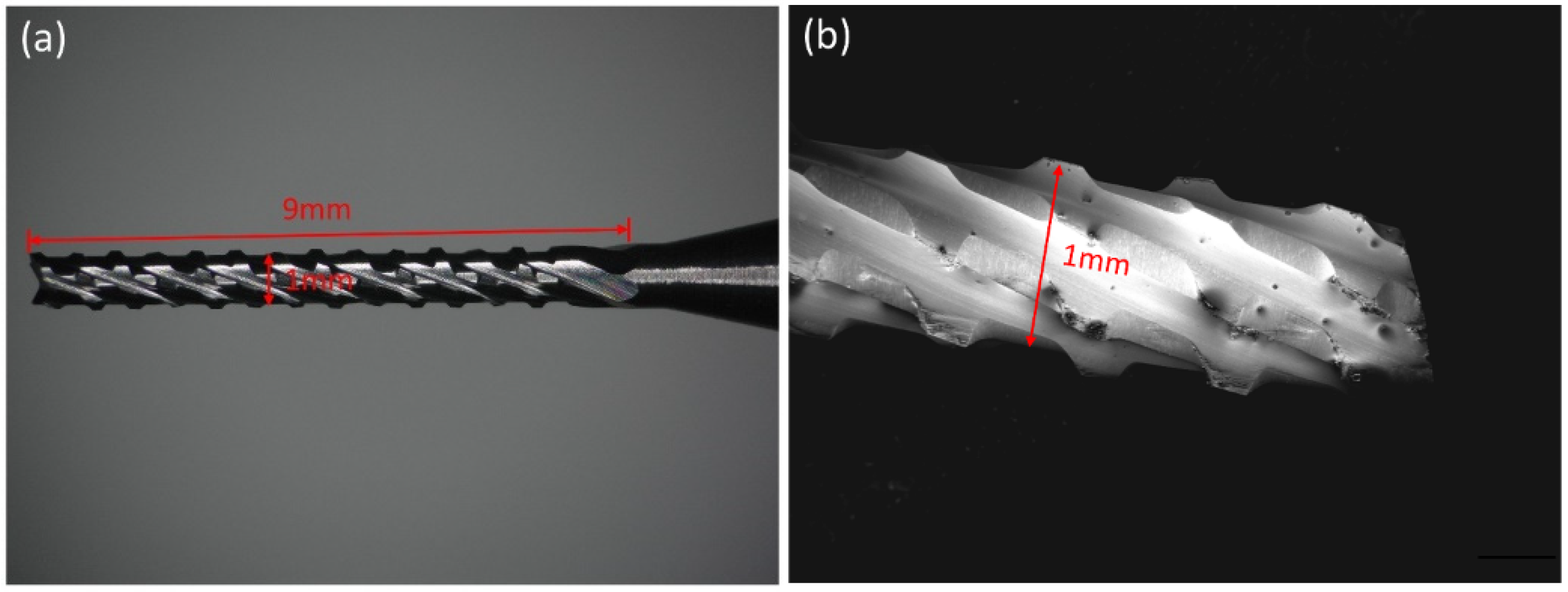
2.3. Milling Experiment

In order to evaluate the service life and wear mechanism of coated milling cutters, IT158 (stack height 6.0 mm, ITEQ, Hsinchu, China), a multifunctional filled epoxy sheet with medium Tg value and high thermal reliability and low coefficient of thermal expansion, was used as the machining material, while the glass fiber contained in the copper-clad sheet would lead to severe tool-wear during machining. The experimental machining machine was selected as a PR-2228/S4 machining center, the air-cooling method was used for cooling during machining and the experimental set unit milling length was 0.55 m. The copper-clad plate IT158 was fixed on the mounting plate and the chips generated were carried away by a vacuum cleaner. The machining process is shown in Figure 2. The experimental parameters are listed in Table 3, while uncoated milling cutters were used for comparison. Considering the wear variation and contingency of coated milling cutters under the same conditions, two tests were repeated under each condition to verify the repeatability. The wear of PCB milling cutters was obtained using a VHK-2000 digital microscope (KEYENCE, Ōsaka, Japan) at milling lengths of 1.1, 3.3 and 5.5 m, with intermittent observations during tool breakage, and the wear pattern was obtained by scanning electron microscopy. Finally, the total milling lengths, wear values and wear mechanisms of the PCB slots machined by the coated milling cutters with different milling parameters were obtained. Figure 3 shows the wear of the tool. According to the international standard (ISO 8688-2:1989) [18], the wear standard is the rear face wear width (VB) of the tool, and the tool wear can be quantitatively determined by measuring the rear face wear width value.

3. Results and Discussion

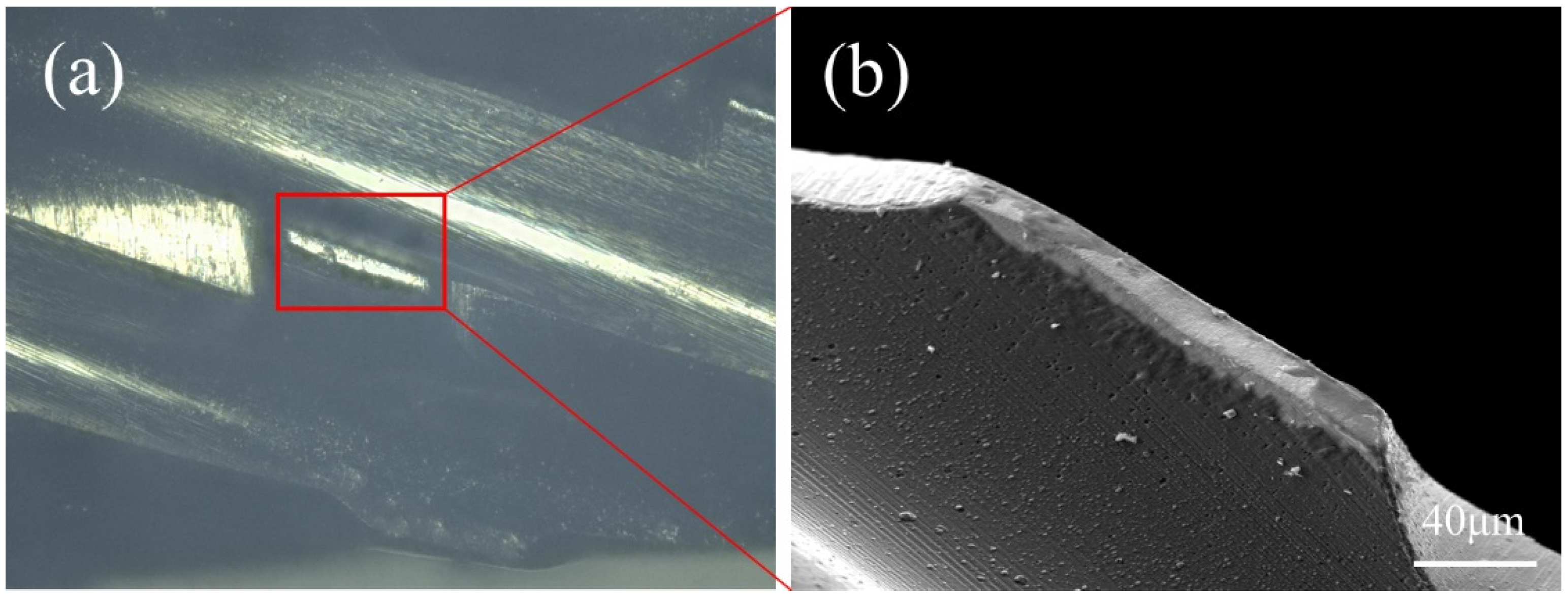
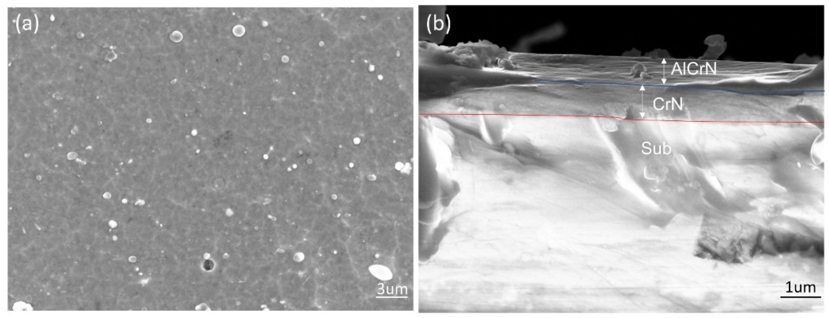
3.1. Microscopic Morphology of the Coating

SEM was used to observe the surface and cross-sectional morphology of the CrN/AlCrN coating, as shown in Figure 4. Large particles and pits with different sizes were observed on the coating surface, and the particle and pit sizes were counted and found to be in the range 1–3 μm. Compared to the large particle size of the AlCrN coating, which is usually in the range 1–10 μm [19], CrN/AlCrN coatings show better surface quality, as evidenced by the dense coating surface, the absence of visible defects and the smaller size of large particles. These tiny droplets are mainly emitted from the cathode point, where atomic and ionic collisions promote their formation on the substrate during the deposition process. Since the poor adhesion of these droplet particles affects the surface quality and mechanical properties of the coating, many studies have been conducted to reduce the large particles through adjusting the process parameters. For example, an appropriate increase in the magnitude of the arc current can reduce the number and size of particles on the surface of the coating [20]. The cross-sectional morphology of the coating in Figure 4b shows that the coating is flat and dense as well as there being no obvious boundary between the layers; the thickness of the top layer of CrN/AlCrN is 0.8 ± 0.11 μm and the middle layer of CrN is 1.0 ± 0.08 μm.

3.2. Coating Composition and Phase Composition

Figure 5 shows the elemental energy spectrum of the coating surface. The coating is mainly composed of Al: 30.46 at.%, Cr: 18.80 at.% and N: 50.74 at.%, where N is the main constituent element, which is mainly related to the N2 flux. In the subsequent energy spectral surface scans, the constituent elements were found to be uniformly distributed on the surface of the coating. The analysis of the line scan spectra of the elements of the coating cross-section is shown in Figure 6. The values of the vertical coordinates represent the elemental content of the coating as the coating thickness changes, and the distribution pattern of the elemental content of Al, Cr and N is generally consistent with the content of the surface scan.
The results of the XRD diffraction spectrum in Figure 7 show that the three diffraction peaks of the coating ((111), (200) and (220)) are located at 38.53, 44.77 and 65.19, respectively, while the crystallinity in the (200) direction is good. Based on the XRD results, the crystal size of the coating was obtained by Scherrer’s theoretical equation [21]: D = K λ / ( β cos θ ) , where K is a constant (0.9), λ is the wavelength of the X-rays (0.15406 nm), β is the value of the radian corresponding to the full width at half maximum (FWHM) of the coating (200) peak and θ is the Bragg angle. The grain size obtained was 18.65 nm.

3.3. Hardness and Surface Roughness of the Coating

The surface morphology of the coating and the substrate is shown in Figure 8. It can be found that the surface morphology of the substrate is smooth before and after coating, which indicates that the roughness is not significantly changed after coating. The roughness value of the substrate is 70 nm and the roughness value of the surface is 120 nm with coating, and the change in roughness value is consistent with the surface morphology. The hardness of the coating was measured by a micro-Vickers hardness tester, and the average hardness value of the coating was 3512 HV0.025, which is 59.1% higher than that of the substrate (2208 HV0.025). Therefore, the deposited CrN/AlCrN coating has good mechanical properties without significantly changing the surface quality of the substrate.

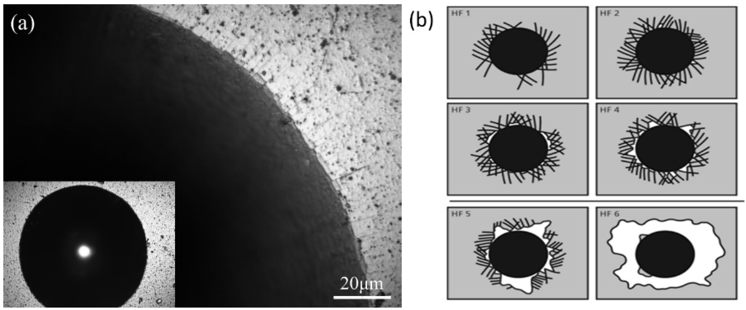
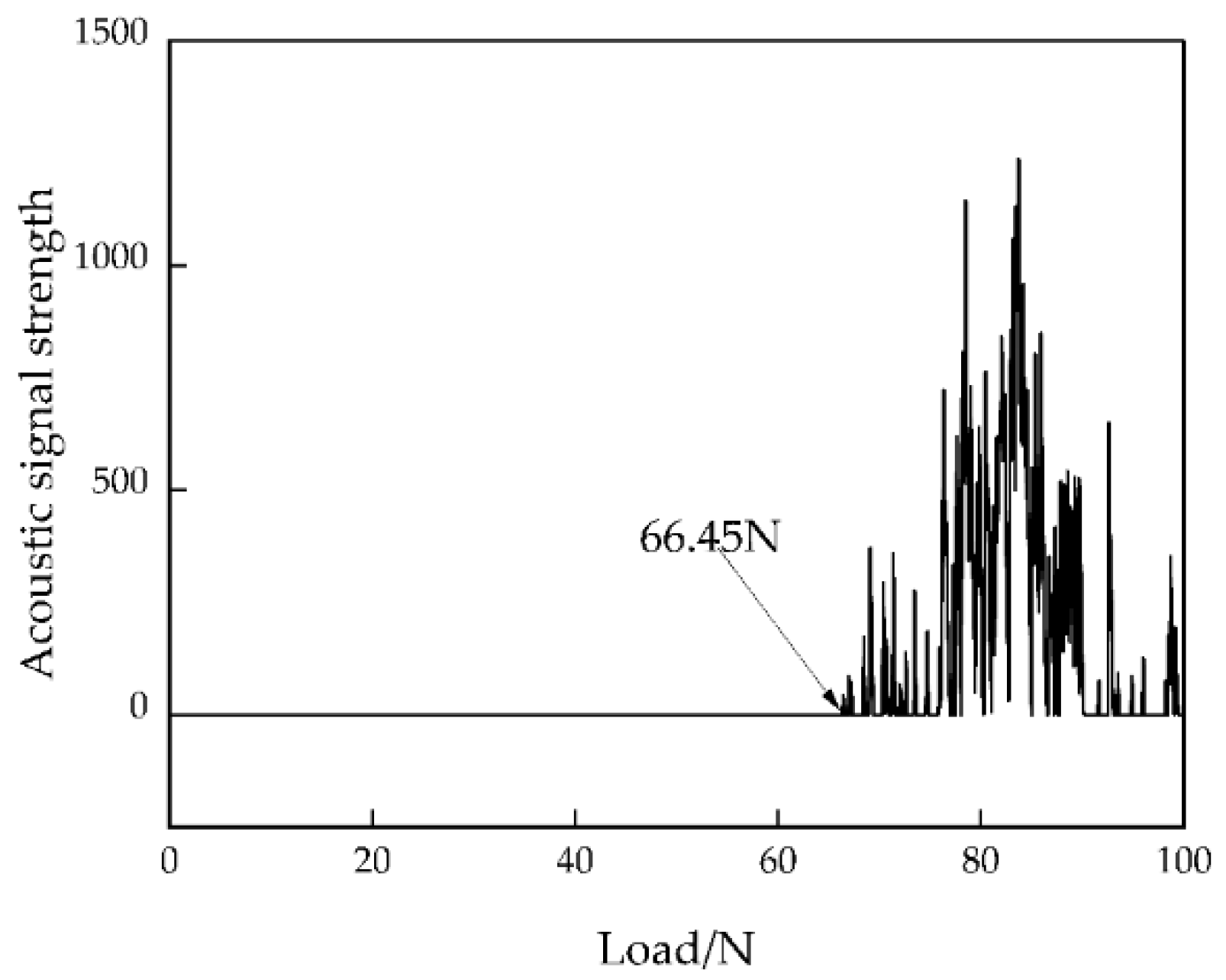
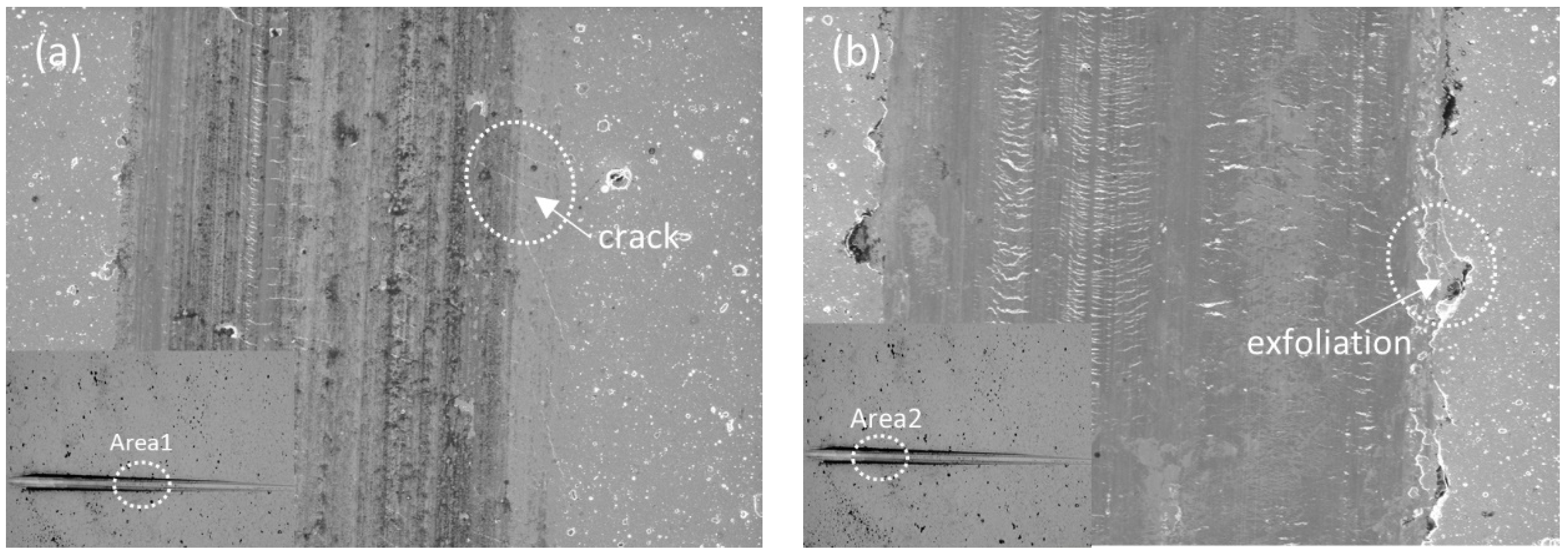
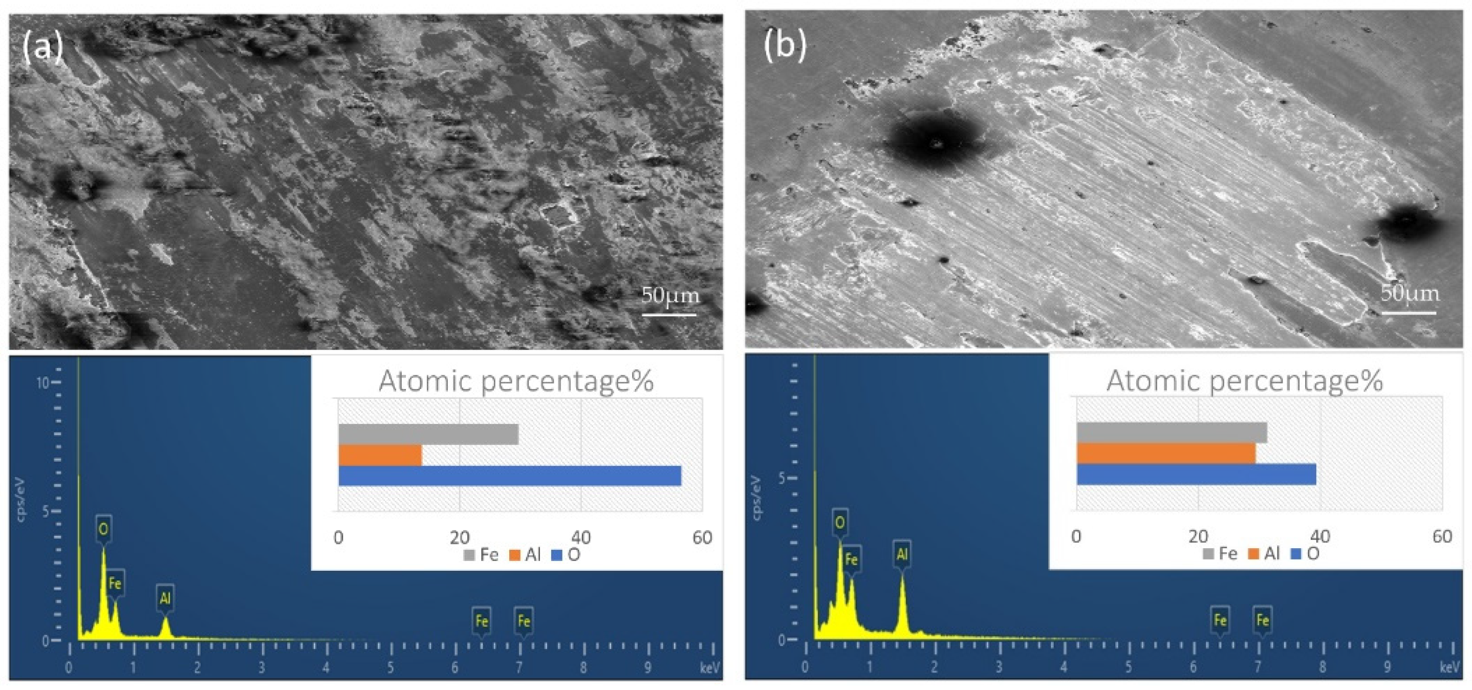
3.4. Bonding Strength of the Coating

In the high-speed milling process of PCB, the bonding strength of coating and substrate has an important influence on the tool life of the coated milling cutters. If the bonding strength between the coating and substrate is poor, coating delamination and spalling will become the main failure form, resulting in low service life of the coated tools. According to the determination criteria in Figure 9b, the bonding strength level is divided into HF1–HF6 from high to low, and there are damage modes such as cracks around the indentation (HF1–HF6) and coating flaking (HF5, HF6). When the conical diamond indenter is pressed against the specimen, both the coating and the substrate will show plastic deformation. In addition, the coating and substrate undergo significant radial tensile strain during the applied load, and circumferential cracks with different numbers and lengths appear at the edges of the indentation area. The indentation pattern of the CrN/AlCrN coating is observed in Figure 9a, which shows that the number of cracks around the indentation is small, the length of cracks is not significantly extended and there is no peeling on the surface of the coating, thus the bonding strength of the CrN/AlCrN coating is HF1.
The bonding force of the coating was tested using a scratch tester, and from Figure 10 the acoustic signal curve of the scratches, it can be found that the curve starts to fluctuate when the applied load is 66.45 N, indicating that the bonding force Lc2 of the CrN/AlCrN coating is 66.45 N. The scratch morphology of the coating is shown in Figure 11, with fine cracks at coating area 1, a few fragments at the edges of the scratches and whisker-like flaking at the crack fragments. It is clear from area 2 that the coating has peeled off extensively.

3.5. Tribological Test

When PCBs are machined using coated milling cutters, the quality and accuracy of the machining is related to the tribological properties of the coating. Experiments were conducted using a ring-on-block tester, and the friction coefficient value curve of the coating is shown in Figure 12. It can be seen from the figure that the friction coefficients are different under different experimental loads. Under the load of 20 N, the friction coefficient grows rapidly in the early stage, and the friction coefficient curve is smooth and keeps stable at about 0.45 at 200 s. The friction coefficient grows faster in the late stage of wear, mainly due to the serious wear of the coating. When the load is 12 N, the friction coefficient curve is relatively smooth, with values fluctuating around 0.4, and the friction coefficient starts to grow rapidly after 350 s. Comparing the friction coefficient curves under both loads, it can be found that the friction coefficient of the coating under both loads did not show a jump increase, which is mainly due to the excellent bonding strength of the coating [22]. In addition, the coating exhibited better friction performance at low loads, as evidenced by lower and smoother friction coefficient values. The wear tracks of the coatings were observed using scanning electron microscopy and energy dispersive spectroscopy (EDS) was performed to investigate the wear mechanisms of the coatings. From the surface wear morphology and EDS mapping in Figure 13, various defects were found on the surface of the coating with the load of 12 N, which was mainly due to the adhesion of the coating to the opposing ring. In the EDS spectrum, it was found that in addition to the coating elements, a large amount of O and Fe elements were also present, and Fe elements were mainly transferred with Fe elements on the opposing ring. Therefore, under light load, the coating wear mechanisms are mainly adhesive wear and oxidation wear. Under a heavy load of 20 N, the ploughing phenomenon caused by the ploughing of hard particles exists on the coating surface, and a certain amount of O and Fe elements are present in the subsequent EDS spectrum.

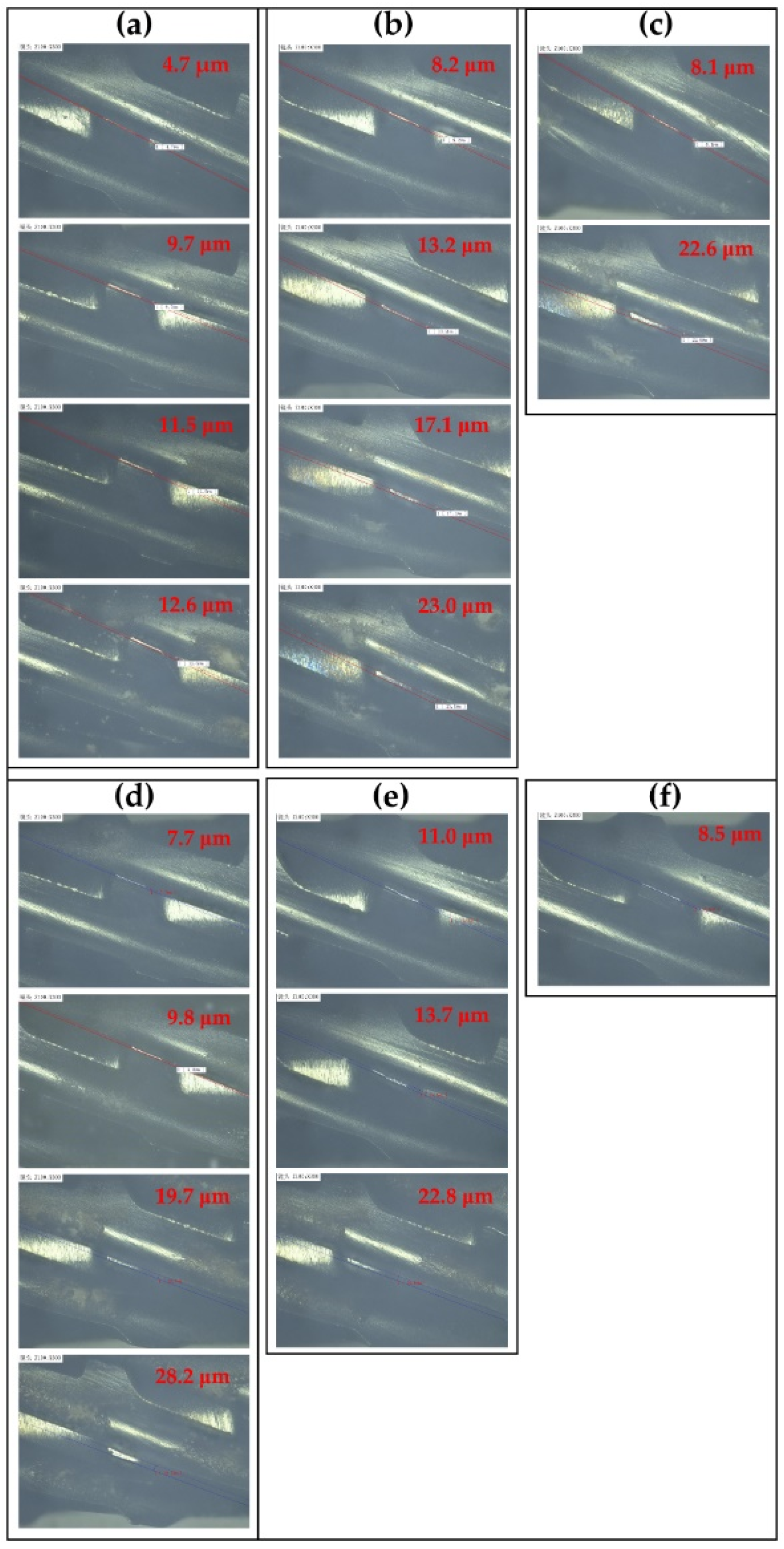
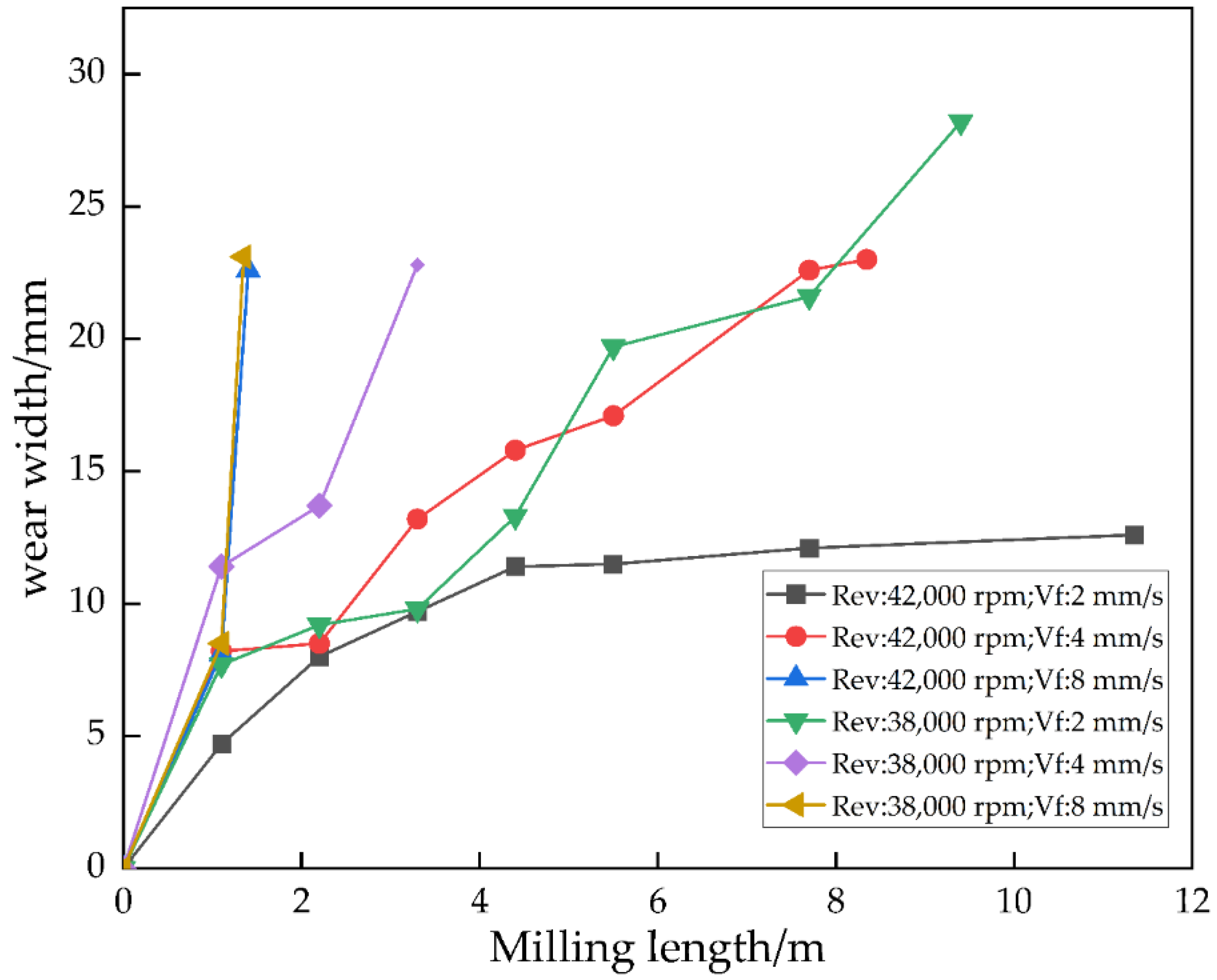
3.6. Milling Experiment

To study the wear mechanism and service life of the coated milling cutter, the wear of the cutting edge of the PCB milling cutter under different milling parameters and the relationship between the wear of the tool surface and the total milling length were observed intermittently by digital microscopy, as shown in Figure 14 and Figure 15. It can be found that the tool wear increases with the increasing in cutting length. When the rotating speed is 42,000 rpm and the feed rate is 2 mm/s, the maximum wear of the milling cutter is 12.6 μm; when the feed rate increases to 4 mm/s, the maximum wear of the milling cutter is 23.0 μm; when the feed rate increases to 8 mm/s, the flank wear of the milling cutter quickly reaches 22.6 μm and tool breakage occurs. When the rotating speed is 38,000 rpm and the feed rate is 2 mm/s, the maximum wear of the milling cutter is 28.2 μm; when the feed speed is increased to 4 mm/s, the maximum wear of the milling cutter is 22.8 μm; when the feed speed is increased to 8 mm/s, the breakage occurs after 8.5 μm wear. Comparing only the spindle speed, the higher spindle speed for cutting at the same feed rate and milling distance results in less tool wear, so the higher spindle speed is more beneficial to the milling process. The experiments were carried out at the feed rates of 2, 4 and 8 mm/s, and the tool wear increased with the increasing feed speed for the same milling tool length. Therefore, the coated milling cutter has better milling performance and service life at higher spindle speed and lower feed rate.
The total milling lengths of coated and uncoated milling cutters with different milling parameters are plotted in Figure 16, from which it can be found that the service life of coated milling cutters is improved by 9.08, 6.88, 0.76, 7.39, 4.66 and 0.18 m compared with uncoated milling cutters under different milling parameters. It can be found that the tool life is improved after the coating treatment, especially for the low feed speed. In both spindle speeds when the feed speed is 8 mm/s, the tool life before and after the coating has not changed much, mainly because the higher feed speed makes the tool wear rapidly to the set wear amount, and the rapid wear causes the coating to fall off.
When using PCB milling cutters for high-speed milling with different parameters, the problems faced include not only the friction between the milling cutter and the cutting material, but also the intermittent impact force caused by intermittent milling, both of which may cause rapid wear and even sudden breakage of the cutter. The experimental results show that the total milling length of uncoated milling cutters processing PCB slots under different milling parameters is not more than 3 m when breakage occurs. When the milling cutter wears, the cutting edge of the uncoated cutter cannot withstand the high frictional resistance, which will lead to rapid fracture when milling the PCB slot, so the wear resistance of the uncoated cutter is poor.
When coated milling cutters are used for PCB slot machining, the wear of the milling cutter mainly depends on the friction coefficient of the coating, surface roughness and bonding strength, which mainly affect the friction performance, chip evacuation ability and cutting force during PCB milling. From previous studies, it is known that coated milling cutters with larger friction coefficients and surface roughness are more susceptible to severe abrasive wear and large frictional resistance than those with low friction coefficients and surface roughness. With the gradual increasing of the tool wear, the frictional resistance and cutting force between the edge of the end mill and the PCB will instantly exceed the load-bearing capacity, leading to the breakage of the PCB milling cutter. As the CrN/AlCrN-coated milling cutter has a low coefficient of friction, it will reduce the frictional resistance and slow down the wear rate of the milling cutter during the milling process, and the lower surface roughness will give the milling cutter excellent chip evacuation ability. Indentation tests have shown that the CrN/AlCrN coating has excellent bond strength and that the coating does not delaminate or even flake off from the tool prematurely during high-speed milling of PCB grooves. Therefore, the cutting edge is well protected from severe wear caused by the high-hardness fillers (SiO2, Al2O3, etc.) in the PCB. The results show that the CrN/AlCrN-coated milling cutter has better cutting performance and service life than the uncoated cutter.
The wear of the coated milling cutter for different milling parameters obtained using SEM photography is shown in Figure 17. When the rotating speed is 42,000 rpm and the feed rate is 2 mm/s, the cutting edge is slightly worn without any built-up edge and coating flaking, and when the feed rate is increased to 4 mm/s, the wear of the cutting edge of the coated milling cutter is further intensified. Figure 17d–f show the experimental wear patterns obtained at a lower spindle speed of 38,000 rpm, which shows the more severe wear of the coated tool at the same feed rate compared to the higher spindle speed. Therefore, the failure of the coated milling cutters is mainly in the form of severe wear, blade peeling and built-up edge.

4. Conclusions

(1)
The surface of the CrN/AlCrN coating is dense and free of obvious defects, and the multilayer structure has no obvious boundary. The coating consists of Al, Cr and N elements and is uniformly distributed. After coating, the roughness increased by 50 nm, the microhardness increased by 59.1% and the bonding force was 66.45 N.
(2)
In the tribological test, the friction coefficient increased with the increase in load. The average friction coefficient at the load of 12 N was 0.4. The wear mechanisms of the coating were adhesive wear and oxidative wear. At the load of 20 N, the average friction coefficient was 0.45, and the wear mechanisms were abrasive and oxidative wear.
(3)
The coated PCB milling cutter had better milling performance and higher service life at higher spindle speed and lower feed rate for slot machining. As the feed rate increased, the wear of the coated tool gradually increased at the same milling length. When the spindle speed was 42,000 rpm and the feed rate was 2 mm/s, the total milling length of the printed circuit board processed by the coated milling tool was up to 11.35 m.
(4)
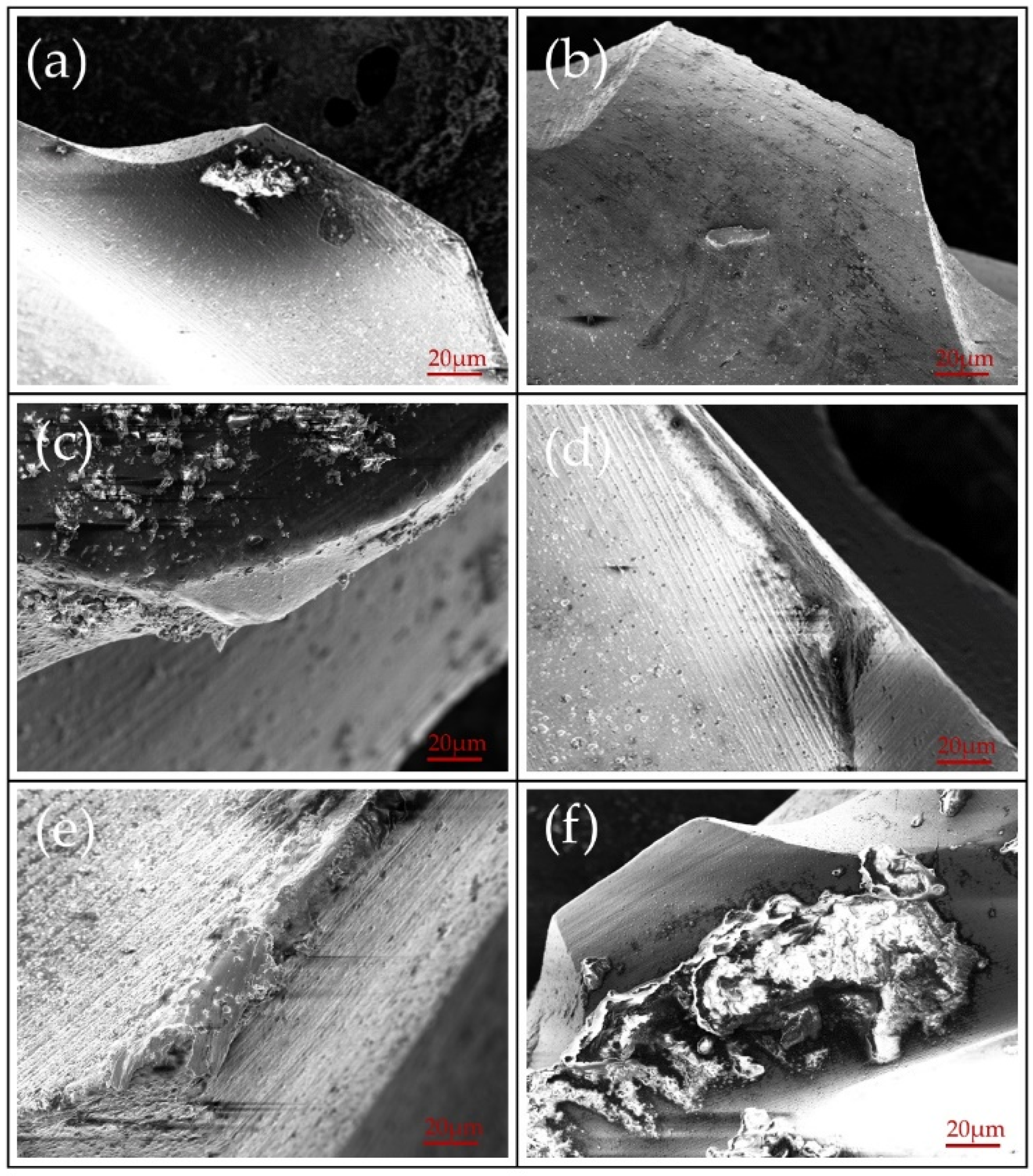
Compared with the uncoated milling cutter, the coated milling cutter showed better wear resistance and cutting performance. Under suitable milling parameters, the service life of the coated milling cutter quadrupled over the uncoated milling cutter. The failure of the coated milling cutters was mainly in the form of severe wear, blade peeling and built-up edge.

Author Contributions

Conceptualization, R.W. and H.Y.; methodology, Z.G.; formal analysis, R.W.; writing—original draft preparation, R.W.; writing—review and editing, S.W.; supervision, R.L.; project administration, R.L.; funding acquisition, R.L. All authors have read and agreed to the published version of the manuscript.

Funding

This research was supported by the University-Industry Cooperation Project of Fujian Province (Grant No. 2021H6031), the Collaborative Special Project for Fuxia-Quan Autonomous Region (Grant No. 3502ZCQXT2021004), the Major Science and Technology Project of Xiamen City (Grant No. 3502Z20191022) and the Educational Research Project for Young and Middle-aged Teachers of Fujian Province (Grant No. JAT210253).

Institutional Review Board Statement

Not applicable.

Informed Consent Statement

Not applicable.

Data Availability Statement

Not applicable.

Conflicts of Interest

The authors declare no conflict of interest.

References

  1. Shi, H.; Liu, X.; Lou, Y. Materials and micro drilling of high frequency and high speed printed circuit board: A review. Int. J. Adv. Manuf. Technol. 2019, 100, 827–841. [Google Scholar] [CrossRef]
  2. Leng, J.; Ruan, G.; Song, Y.; Liu, Q.; Fu, Y.; Ding, K.; Chen, X. A loosely-coupled deep reinforcement learning approach for order acceptance decision of mass-individualized printed circuit board manufacturing in industry 4.0. J. Clean. Prod. 2021, 280, 124405. [Google Scholar] [CrossRef]
  3. Varun, K.; Manan, G. Comparative study of different natural fibre printed circuit board (PCB) composites. Mater. Today Proc. 2021, 44, 2097–2101. [Google Scholar] [CrossRef]
  4. Park, J.; Wie, K.; Park, J.; Ahn, S. Evaluation of machinability in the micro end milling of printed circuit boards. Proc. Inst. Mech. Eng. Part B J. Eng. Manuf. 2009, 223, 1465–1474. [Google Scholar] [CrossRef]
  5. Zheng, L.; Wang, C.; Yang, L.; Song, Y.; Fu, L. Characteristics of chip formation in the micro-drilling of multi-material sheets. Int. J. Mach. Tools Manuf. 2012, 52, 40–49. [Google Scholar] [CrossRef]
  6. May, P.; Ashfold, M.; Mankelevich, Y.A. Microcrystalline, nanocrystalline, and ultrananocrystalline diamond chemical vapor deposition: Experiment and modeling of the factors controlling growth rate, nucleation, and crystal size. J. Appl. Phys. 2007, 101, 053115. [Google Scholar] [CrossRef] [Green Version]
  7. Mircea, A. The optimization of printed circuit board manufacturing by improving the drilling process productivity. Comput. Ind. Eng. 2008, 55, 279–294. [Google Scholar] [CrossRef]
  8. Huang, X.; Wang, C.; Yang, T.; He, Y.; Li, Y.; Zheng, L. Wear characteristics of micro-drill during ultra-high speed drilling multi-layer PCB consisting of copper foil and ceramic particle filled GFRPs. Procedia CIRP 2021, 101, 326–329. [Google Scholar] [CrossRef]
  9. Shen, B.; Sun, F.-H.; Xue, H.-G.; Chen, M.; Zhang, Z. Study on fabrication and cutting performance of high quality diamond coated PCB milling tools with complicated geometries. Surf. Eng. 2009, 25, 70–76. [Google Scholar] [CrossRef]
  10. Kumar, K.M.; Nithin Tom, M.; Baburaj, M. Sustainable milling of Ti-6Al-4 V super alloy using AlCrN and TiAlN coated tools. Mater. Today Proc. 2022, 50, 1732–1738. [Google Scholar] [CrossRef]
  11. Li, H. High-Speed Milling of Microwave Printed Circuit Boards Using TiN Coated Tools. Master’s Thesis, Nanjing University of Aeronautics and Astronautics, Nanjing, China, 2012. [Google Scholar]
  12. Lee, H.Y.; Nam, K.H.; Yoon, J.S.; Han, J.G.; Jun, Y.H. Industrial application of WC–Ti(1−x)AlxN nanocomposite films synthesized by cathodic arc ion plating process on a printed circuit board drill. Surf. Coat. Technol. 2001, 146–147, 532–536. [Google Scholar] [CrossRef]
  13. Yao, S.H.; Su, Y.L.; Kao, W.H.; Cheng, K.W.; Su, C.T. Nanolayer CrNx/WNy coatings used on micro drills for machining of printed circuit boards. J. Mater. Process. Technol. 2010, 210, 660–668. [Google Scholar] [CrossRef]
  14. Lin, Z.-C.; Ho, C.-Y. Performance of coated tungsten carbide tools on milling printed circuit board. J. Mater. Process. Technol. 2009, 209, 303–309. [Google Scholar] [CrossRef]
  15. Chen, W.; Zheng, J.; Meng, X.; Kwon, S.; Zhang, S. Investigation on microstructures and mechanical properties of AlCrN coatings deposited on the surface of plasma nitrocarburized cool-work tool steels. Vacuum 2015, 121, 194–201. [Google Scholar] [CrossRef]
  16. Kumar, T.S.; Jebaraj, A.V. Metallurgical characterization of CrN and AlCrN physical vapour deposition coatings on aluminium alloy AA 6061. Mater. Today Proc. 2020, 22, 1479–1488. [Google Scholar] [CrossRef]
  17. Yemurai, V.; Arash, F.-A.; Hassan, E.; Omid, I. Influence of post-deposition annealing temperature on morphological, mechanical and electrochemical properties of CrN/CrAlN multilayer coating deposited by cathodic arc evaporation- physical vapor deposition process. Surf. Coat. Technol. 2022, 432, 128090. [Google Scholar] [CrossRef]
  18. ISO 8688-2: 1989; Tool Life Testing in Milling—Part 2: End Milling. S/OL. International Organization for Standardization: Geneva, Switzerland, 1989.
  19. Warcholinski, B.; Gilewicz, A.; Myslinski, P.; Dobruchowska, E.; Murzynski, D. Structure and properties of AlCrN coatings deposited using cathodic arc evaporation. Coatings 2020, 10, 793. [Google Scholar] [CrossRef]
  20. Zhu, S.; Qin, Y.; Mei, H. Influence of Arc Current on Surface Properties and Corrosion Resistance of AlCrN Coatings Deposited by Multi-arc Ion Plating. Int. J. Electrochem. Sci 2020, 15, 5352–5361. [Google Scholar] [CrossRef]
  21. Tang, J.-F.; Lin, C.-Y.; Yang, F.-C.; Chang, C.-L. Influence of Nitrogen Content and Bias Voltage on Residual Stress and the Tribological and Mechanical Properties of CrAlN Films. Coatings 2020, 10, 546. [Google Scholar] [CrossRef]
  22. Kenzhegulov, A.K.; Mamaeva, A.A.; Panichkin, A.V.; Prosolov, K.A.; BroŃczyk, A.; Capanidis, D. Investigation of the adhesion properties of calcium-phosphate coating to titanium substrate with regards to the parameters of high-frequency magnetron sputtering. Acta Bioeng. Biomech. 2020, 22, 111–120. [Google Scholar] [CrossRef] [PubMed]
Figure 1. PCB end mills: (a) the overall groove of the end mill; (b) the partial cutting edge of the end mill.
Coatings 12 00556 g001
Figure 2. PCB processing.
Coatings 12 00556 g002
Figure 3. Wear of PCB tool: (a) PCB tools; (b) Local zoom.
Coatings 12 00556 g003
Figure 4. Coating microscopic morphology: (a) Surface appearance; (b) Cross-sectional shape.
Coatings 12 00556 g004
Figure 5. Surface energy spectrum analysis of coatings.
Coatings 12 00556 g005
Figure 6. Elemental line scan spectra of the cross-sections of the coating.
Coatings 12 00556 g006
Figure 7. XRD pattern of the coating.
Coatings 12 00556 g007
Figure 8. Three-dimensional morphology and line profile curves: (a) coating; (b) substrate.
Coatings 12 00556 g008
Figure 9. (a) Indentation profile of the coating; (b) VDI-3198 standard.
Coatings 12 00556 g009
Figure 10. Acoustic signal curve of scratches.
Coatings 12 00556 g010
Figure 11. Scratch appearance of the coating: (a) Area 1; (b) Area 2.
Coatings 12 00556 g011
Figure 12. Friction coefficient curve.
Coatings 12 00556 g012
Figure 13. Microscopic morphology and elemental analysis of coated abrasion marks: (a) 12 N; (b) 20 N.
Coatings 12 00556 g013
Figure 14. Typical wear patterns of the cutting edges of coated milling cutters with different milling parameters: (a) Rev: 42,000 rpm; Vf: 2 mm/s; (b) Rev: 42,000 rpm; Vf: 4 mm/s; (c) Rev: 42,000 rpm; Vf: 8 mm/s; (d) Rev: 38,000 rpm; Vf: 2 mm/s; (e) Rev: 38,000 rpm; Vf: 4 mm/s; (f) Rev: 38,000 rpm; Vf: 8 mm/s.
Coatings 12 00556 g014
Figure 15. Flank wear value of the cutting edge of coated milling cutters with different milling parameters.
Coatings 12 00556 g015
Figure 16. Total milling length for coated and uncoated milling cutters with different milling parameters: (a) Rev: 42,000 rpm; Vf: 2 mm/s; (b) Rev: 42,000 rpm; Vf: 4 mm/s; (c) Rev: 42,000 rpm; Vf: 8 mm/s; (d) Rev: 38,000 rpm; Vf: 2 mm/s; (e) Rev: 38,000 rpm; Vf: 4 mm/s; (f) Rev: 38,000 rpm; Vf: 8 mm/s.
Coatings 12 00556 g016
Figure 17. Micromorphology of coated milling cutters with different milling parameters: (a) Rev: 42,000 rpm; Vf: 2 mm/s; (b) Rev: 42,000 rpm; Vf: 4 mm/s; (c) Rev: 42,000 rpm; Vf: 8 mm/s; (d) Rev: 38,000 rpm; Vf: 2 mm/s; (e) Rev: 38,000 rpm; Vf: 4 mm/s; (f) Rev: 38,000 rpm; Vf: 8 mm/s.
Coatings 12 00556 g017
Table 1. Cemented carbide specimen composition.
ModelWC%Co%Graininess
K0593.006.200.4
Table 2. Geometric parameters of the tool.
External
Diameter
Blade LengthFull LengthNumber of BladesLateral Groove DepthTooth
Height
Spiral
Angle
1.0 mm28.0 mm37.0 mm70.070 mm0.16 mm12°
Table 3. Milling experiment parameters.
ProgramsSpindle Speed (rpm)Feeding Speed (mm/s)
Program 142,0002
Program 242,0004
Program 342,0008
Program 438,0002
Program 538,0004
Program 638,0008
Publisher’s Note: MDPI stays neutral with regard to jurisdictional claims in published maps and institutional affiliations.

