Abstract
A mathematical model of the cavity flow of the fan nozzle, a mathematical model of jet atomisation, and a simplified physical model of the equivalent entity are established. A simulation of the spraying flow at different spraying pressures is carried out using a 0.48 calibre nozzle as a case study, and compared with experimental data; error results between 4.3% and 7.5% indicate the simulation means used are reliable and the simulation model is valid. The simulation means include using the effective simulation model to further explore the evaluation index of atomisation characteristics; in the critical Weber number on the impact of atomised particles, analysis of the impact of the critical Weber number on the diameter of atomised particles and the speed of movement, and determining the critical Weber number; atomisation spraying effect, for atomisation pressure on atomised particle diameter, speed of movement, impact kinetic energy, deposition rate, and liquid film growth, etc. The results show that, in the existing high-pressure airless spraying equipment within the range of permissible pressure 6~16 MPa, with the increase in atomisation pressure, the better the atomisation effect of the paint, the better the atomised particle spraying adhesion deposition rate of the paint, and the better the overall spraying effect.
1. Introduction
Due to the high corrosiveness and wave impact of the deep sea operation area, the coating and anti-corrosion of large-scale offshore engineering equipment is very important. Meanwhile, the development of sea transportation and river transportation also requires the improvement of production capacity [1].
The coating of a ship’s outer plate is the last process of shipbuilding production in the shipyard. In this last process, once the quality problem of spraying occurs, the workers will rework, so that the coating of the steel plate primer has to be destroyed. This kind of rework due to the coating quality problem of the ship’s outer plate will bring huge pressure to the shipyard’s production and scheduling, which is very likely to cause the second docking of the ship, causing significant economic losses, and even affect the delivery of the ship, bringing huge operating pressure to the shipyard.
At present, Polymer-Composite Materials (PCMs) can enhance the durability of marine equipment and protect the working surfaces of marine equipment exposed to environmental factors such as sea water, precipitation, solar radiation, and a variety of mechanical loads during storms [2]. At the same time, it should be noted that of all the known thermosetting polymers used as binders for Composite Materials (CMs), a wide range of properties of epoxy composites allows them to be used as ready-made products or protective covers [1].
At present, China is the world’s largest shipbuilding country, but not a shipbuilding power. In the past 10 years, China, Japan, and South Korea have always maintained the top three places in the world in terms of total shipbuilding tonnage and economic output, and are competing for first place. However, due to the low level of automation, backward manufacturing equipment, and other factors, China is not a shipbuilding power. For a long time, Chinese shipbuilding enterprises have been less profitable than South Korea and Japan.
The 19th National Congress of the Communist Party of China (CPC) pointed out: “Adhere to land and sea coordination, accelerate the building of a maritime power”. The shipbuilding enterprises, which build the major marine equipment, face the arduous task of intelligent transformation and upgrading.
Ship painting is one of the three main manufacturing links in the integrated assembly and construction of “hull, outfit and coating” in shipyards, and is the most arduous and polluting for workers. At present, occupational health problems are obvious, labour costs are extremely high, and the pressure of environmental protection is huge.
The ship’s outer plate spraying is an important part of the ship painting, its construction is difficult, the coating quality requirements are high, the amount of work material is large. With the characteristics of large operating area and complex convergence of curved profile, the existing process is two workers standing on the elevated car basket at a height of 40 meters, one person driving the elevated car and one person holding a high-pressure spray gun to spray paint, as shown in Figure 1.
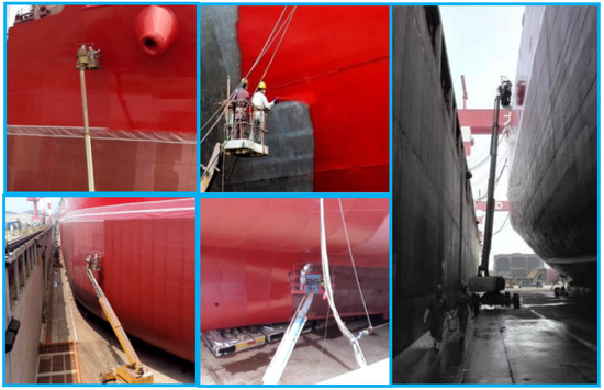
Figure 1.
Current situation of coating on ship’s outer plate in shipyard.
Environmental protection, energy saving and high efficiency of hull surface spraying is the bottleneck of shipbuilding. High-pressure airless spraying is the main process of surface spraying on the inner and outer plates of ship dock, which needs to be pressurized to 15 MPa, and the spray gun keeps 0.2–0.5 m spray distance from the outer plate of the hull. Figure 2 is the work track of ship outer plate coating workers in a shipyard in China. Spray gun along the ship board at a speed of 1 m/s about sweeping spraying, spraying trajectory is “zigzag”, and finally on the surface of the outer hull of the uniform establishment and primer contact good 150 μm antifouling paint film. Spraying fluid motion mechanism, is the basic problem of the study of the quality of spraying, paint spraying effect directly affects the quality of adhesion of the coating, so this paper on high-pressure airless spraying flow field simulation, for the subsequent development of paint mist recovery flow field research to lay the foundation.
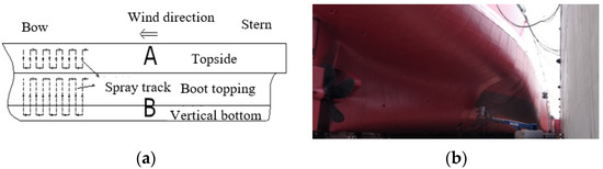
Figure 2.
Manual painting track of ship’s outer plate in a shipyard dock in China. (a) Construction drawing; (b) Physical drawing.
At present, there are the following problems in the ship outer plate spraying process:
- (a)
- Open spraying: spreading paint mist falling into the shipyard dock and polluting the shipyard seaside environment;
- (b)
- Large surface work on the ship’s hull is intensive and inefficient, and once workers are on the elevated car, it is inconvenient to get off and they need to bring diapers, etc. to reduce the number of toilet breaks;
- (c)
- Workers are in a toxic environment for a long time and the toxic paint mist is very harmful to human health;
- (d)
- Workers standing at a height of 40 m have the potential danger of falling, and standing in the gondola of the elevated truck for a long time is hot and sunny in summer and bitingly cold in winter;
- (e)
- Due to the above problems, it is now increasingly difficult to recruit workers, causing serious labour shortages in shipyards.
The use of wall climbing robots with paint mist recovery function to achieve machine replacement can solve the above problems. At present, the US, Europe, Japan, and Korea have developed products, but the cost is expensive and the technology and market are blocked to China. A few domestic institutes have started research on this type of robot, but the process is still in its infancy.
There is more foreign research, mainly in the United States, Germany, and other countries, on the numerical simulation of high-pressure airless spraying. This began in the late 1980s, starting in the United States, gradually developing into more German research in recent years. Supramolecular, chemistry-based self-healing (extrinsic and intrinsic) anti-corrosion coatings have also become a new hot topic; research is directed outward from the field to impact self-healing materials and the inhibition of corrosion processes [3]. As early as the 1980s, the thesis of Lefebvre et al. in the United States was devoted to the basic physical properties of high-pressure airless spraying.
The international situation (except China) is as follows:
In 1993, scientists studied and described the hydrodynamic phenomena of droplet impact, including bouncing, spreading, and splashing from solid surfaces, where cavitation and gas entrainment into the impacted liquid could be observed [4].
In 2004, through fan experiments, scientists investigated the relationship between gun supply pressure, gun-target distance, gun travel speed, target angle, and spray cone angle in spray systems [5].
In 2004, scientists investigated the relationship between the local flow field and wall heat flow in a spherical packed bed and obtained the velocity and temperature fields of the gas as it passed through a periodic wall section test chamber by means of computational fluid dynamics [6].
In 2006, scientists investigated the importance of air in causing splash phenomena with droplet impact [7]. The experimental study and associated computational model simulations provided further insight into the large scale spattering phenomenon, which occurs when paint particles strike and diffuse the initial edge of the liquid and are entrained into the displaced and accelerated air.
In 2010, scientists investigated the effects of droplet velocity, impact angle, and ambient air pressure on the splash threshold and ambient gas motion around the droplet [8]. Experimental observations were made using droplets with a diameter of 1.7 mm, varying droplet velocity, impact angle, and ambient pressure, and the K-H instability was considered to be a suitable instability theory.
In 2013, Qiaoyan Ye et al. conducted an experimental study of the droplet size distribution and droplet velocity required for the simulation by applying a computational fluid dynamics program to the flow field and droplet trajectory, using a Spraytec-Fraunhofer type particle size meter and a laser Doppler anemometer, pointing out the effects of wind speed and spray distance on the target surface transfer efficiency and paint film thickness distribution [9].
In 2013, Mark A et al. proposed a new simulation framework for electrostatic spraying based on a new algorithm for the coupled simulation of airflow, electromagnetic fields, and paint droplets. The compressible solver is based on a finite volume discretization on a dynamic Cartesian octree grid and uses a unique immersion boundary method to model the presence of objects in the fluid, effectively increasing the computational speed [10].
In 2015, Andulkar M V et al. proposed a new method for the automatic generation of offline painting robot trajectories, giving a model of the paint distribution, gun, and task constraints to generate free-form trajectories for robot painting through paint thickness and minimum paint thickness deviation, which dealt flexibly and efficiently with variations in part geometry and paint distribution [11].
In 2018, Qiaoyan Ye et al. conducted a numerical study of the spraying process using three atomisers: a high-speed rotary nozzle, an airless gun, and a pneumatic air gun, and the simulation results showed that the impact droplet characteristics of the three atomisers differed significantly and had a large impact on the performance of the paint film.
In 2021, K Bobzin et al. proposed a new method for metallising thermoplastics by thermal spraying, based on the latest validated predictions of the material response of thermoplastics at relevant temperatures and strain rates. Based on these predictions, high-speed arc spraying was chosen as the coating process. In addition, the process parameters were adjusted to achieve continuous coating [12].
In 2021, Mohsin Abbas et al. used ultrasonic spraying to prepare nano-Zno coated PET and PHBHHx materials for oxygen and UV barrier properties. A chemical deposition method applying ultrasonic spraying (USSC) was explored for the preparation of zinc oxide nanoparticles (ZnO NPs) using ultrasonic spraying. Based on a series of experiments, the most suitable ink composition parameters, ultrasonic spraying process parameters, and number of spraying passes (up to 50× passes) were selected [13,14].
The research situation in China is as follows:
In China, high-pressure airless spraying technology is applied relatively early in the fields of petroleum, chemical industry, and shipbuilding. In the 1990s, China’s shipyards began to apply high-pressure airless spraying construction, but over the years there have been few in-depth studies by relevant scholars. In 2010, relevant studies were conducted by scholars [15]. The main research has the following sections.
In 2011, Teng Yan et al. used the magnesium oxide indentation method and studied the effect of the working parameters such as nozzle equivalent diameter and atomisation pressure on the atomisation effect of paint, and pointed out the relationship between the Sauter mean diameter and characteristic diameter of paint atomisation particles with the variation of atomisation pressure [16].
In 2013, Kang Jin et al. used the Lamina laminar flow model to numerically simulate the internal flow field of fan nozzles, pointing out the relationship between the more the inlet structure changes and the pressure gradient and velocity variation of the flow field [17].
In 2013, Wang Shuangyong et al. carried out a simulation analysis of the internal flow field of high-pressure airless nozzles for man-made panel construction applications, and derived the distribution pattern of the internal pressure and velocity fields of high-pressure airless nozzles [18].
In 2013, Yin Shuo et al. conducted a numerical analysis of the effect of nozzle outlet diameter on the cold spray jet flow field and the optimal position of the substrate, and used the CFD software Fluent to simulate the single-phase free jet and two-phase impact jet flow fields after the nozzle with different outlet diameters [19].
In 2015, Xu Xiaoming et al. carried out a study on the relationship between spray pressure and spray flow of airless spray guns and found that, with the increase in atomisation pressure, the coating spray mass flow rate showed a significant increase in trend [20].
In 2017, Zhang Yong et al. conducted a study on the jet characteristics of supersonic plasma spraying, and in the same year, Wang Haidou et al. analysed the status of the microscopic interaction between the plasma jet and the sprayed particles [21].
In 2018, Sun Yu et al. used the Laminar flow model to numerically simulate the flow field of a grey fan nozzle to find out that the pressure and velocity field clouds are laminarly distributed, and pointed out that the inlet pressure is more reasonable at 15–20 MPa [22].
In 2020, Xie Tianhai et al. did an experimental study on the removal of thermal barrier coatings via a plasma spraying method with abrasive water jets. The results showed that the erosion hole diameter and hole depth increased with the increase in abrasive concentration, jet pressure, punching time, and target distance, and the coating removal rate increased with the increase in abrasive hardness and particle size [23].
In 2022, Yi Zhengyao et al. investigated the macroscopic morphology, microstructure, microhardness, and friction-wear of ZrO2-added NiCrAlY by ultrasonic-assisted direct laser deposition process. Using this method to prepare ZrO2-added NiCrAlY material can effectively improve the metallurgical bonding between the material and the substrate, and obtain a more uniform ceramic distribution as well. Ultrasonic assistance could make the upper surface more smooth and flat [24].
Computational fluid dynamics (CFD) simulation is the main means to study the fluid cavitation effect from a theoretical point of view. In this paper, we explore and summarize the numerical analysis of spraying particle atomisation diameter, particle motion velocity, impact kinetic energy, and liquid film growth at different pressures and spraying distances using fluent software. In particular, we examine the effect of the critical Weber number on the simulation and other laws, aiming to provide reference for subsequent experimental research, so that these laws can be used more effectively to optimize the process parameters.
2. The Research Object and Its Theoretical Model
2.1. Research Object
The research object of this paper is a type of VLCC hull outer plate surface spraying in the case shipyard. Figure 3 shows the current status of their work.
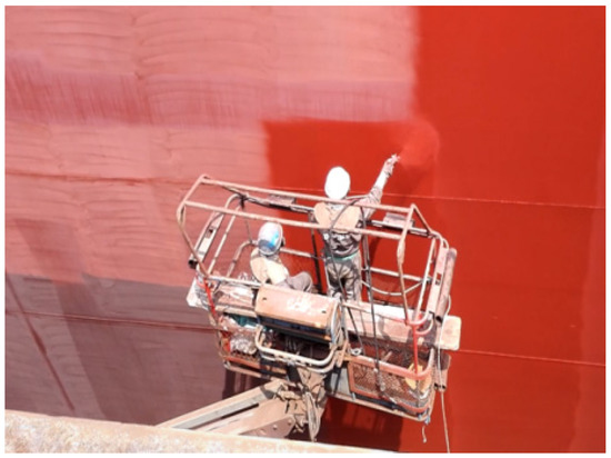
Figure 3.
Current status of hull painting work in a shipyard in Dalian.
The spraying area, spraying distance, and “zigzag” spray trajectory of the hull outer plate surface in the dock are shown in Figure 4.
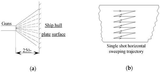
Figure 4.
The current situation of manual work for painting the inner and outer plates of ship docks of the ship dock: (a) Spray gun painting distance; (b) “Zigzag” painting trajectory.
The basic parameters of the spray gun recommended by the paint manufacturer are shown in Table 1.

Table 1.
Spray gun and paint type and working parameters.
Figure 5 is a spraying robot system 2D model design where we see the structure analysis diagram of the spraying robot that can recover the paint mist, respectively showing the internal structure of the spraying robot, the cutting diagram of the recovery cover, and the equipment construction diagram of the wall climbing operation.
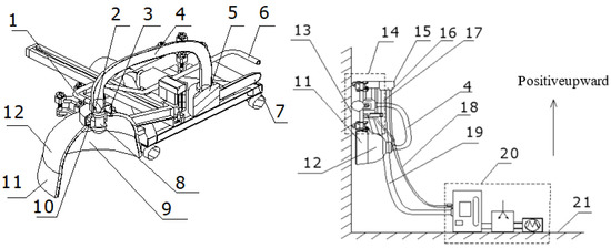
Figure 5.
Spraying robot system 2D model design: 1. Nozzle feed pipe; 2. Paint supply pipe; 3. Vacuum recovery cavity; 4. Vacuum recovery tube; 5. Recovery heater; 6. Paint feeding pipe; 7. Heater recovery tube; 8. Nozzle; 9. Protective; 10. Paint mist recovery hole; 11. Protection cover and seal; 12. The protective cover; 13. Ship plate; 14. The frame of the robot; 15. Free rotation connector; 16. Rotary feed pipe joints; 17. Rotation recovery pipe joint; 18. The feed tube; 19. The recovery of spray robot; 20. The recovery of feeding pipe and ground system; 21. Dock ground.
2.2. Mathematical Model of Cavity Flow
The structure of the exit section of the gun cavity flow mathematical model is shown in Figure 6. The main parameters that determine its structure include the diameter d of the exit cylindrical section, the length L of the cylindrical section, the half angle α of the V-shaped groove, the offset b of the groove, and the depth a of the blind end of the exit.
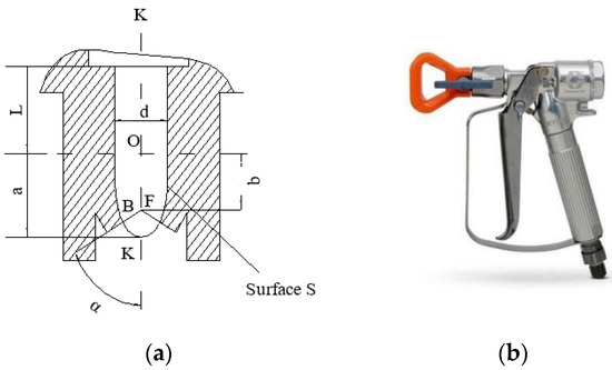
Figure 6.
Nozzle inner chamber exit section structure. (a): Structure diagram; (b): Physical map.
The cavity flow paint component is laminar and turbulent flow, and turbulent flow is chosen for the study in this paper. Let its flow critical Reynolds number Re be 8000–10,000, the paint property density ρ be 1320 kg/m3, and the dynamic viscosity γ be 0.275 kg/(m.s). The paint needs to satisfy the following equations in the flow process.
2.2.1. Continuity Equation
The continuity equation means that the difference between the mass of the fluid flowing into and out of the control body through the control surface should be equal to the increment of the fluid mass inside the control body. Derive the integral equation of the fluid continuity equation in the form shown in Equation (1):
where vol is the control body and A is the control surface. For the flow of an incompressible homogeneous fluid such as paint, the density term is constant to remain constant, so the above equation is transformed into a differential form in the right-angle coordinate system, i.e., the paint maintains the mass conservation equation inside the control body as shown in Equation (2).
2.2.2. Conservation of Momentum Equation
Viscous incompressible fluids need to conform to the conservation of momentum equations during flow, namely the Navier–Stokes equations. The expression of this equation in vector form under the inertial reference system is shown in Equation (3).
where p is the static pressure which is the pressure of the paint inside the nozzle and represents the external volume force. Paint flowing inside the nozzle belongs to the incompressible fluid flow; its viscosity and density are constant and remain unchanged. Equation (3) in the right-angle coordinate system is shown in Equation (4).
where ρ is the density of the paint, (u,v,w) and (FX,FY,FZ) are the velocity components of the paint at the position (x,y,z) at time t and the components of the external force, respectively, μ is the dynamic viscosity of the paint, which is a constant, and ∆ is the Laplace operator.
2.3. Mathematical Model of Atomisation Mathematical Model
The CFD software combines theoretical derivation and experiment to propose a mathematical model of fan spraying Flat-Fan-Atomizer atomization model that is more compatible with high-pressure airless spraying, which considers that the jet is ejected from a slender nozzle to form a flat liquid film, and then broken under the action of air to form droplets. The basic principle of this model is the same as that of the Pressure-Swirl Atomizer model. The mechanism of interaction between air and the liquid film is not clear, and it is generally believed that the aerodynamic instability causes the liquid film to break up. The assumed mathematical model suggests that the growing Kelvin–Helmholtz wave on the liquid film causes the final liquid to break up into lines. The further fragmentation of the linear droplet into droplets is then due to varus instability. Once a droplet is formed, its state of motion is affected by drag, collisions, merging, and secondary fragmentation.
The thickness t of the liquid film jet ejected from the nozzle is related to the mass flow rate defined by Equation (5)
where dinj is the equivalent nozzle diameter (m); M is the equivalent mass flow rate (kg/m3), u is the axial velocity at the exit of the paint nozzle (m/s); and ρ is the paint density (kg/m3). The total velocity of the paint at the nozzle outlet is related to the nozzle pressure.
∆p in Equation (6) represents the pressure difference between inlet and outlet (MPa) and kv is the velocity coefficient. The spraying process should satisfy the energy conservation equation and sufficient mass flow rate, which is related to the nozzle’s internal structure and pressure. The expression is shown in Equation (7).
The axial velocity of the paint u is shown in Equation (8).
where U is the total velocity of the paint (m/s) and θ is a known amount of spray diffusion angle. After the initial atomisation of droplets, secondary fragmentation occurs when the droplets interact with the surrounding air due to their large diameter. The random secondary droplet model treats the fragmentation process with particle diameter distributed in a certain range as a random discrete event. The secondary fragmentation model calculates the time of fragmentation and the number of new particles; if the particle diameter is greater than a certain critical diameter, the particle will be fragmented. The critical value of the critical Weber number formula shown in Equation (9).
where We is the liquid Weber number; ρg is the air density (kg/m3); ua is the relative velocity between the droplet and the air (m/s); r is the droplet radius (m); and σ is the droplet surface tension coefficient (N/m).
2.4. Evaluation Indicators for Atomisation Characteristics
The evaluation of droplet atomisation can be defined using the mean diameter Dj,k, as shown in Equation (10).
where j and k are integers and f(D) is the droplet diameter distribution function. Depending on the value of j and k, the mean diameter represents different meanings; Table 2 shows some common mean diameter definitions.
Table 2.
The definition of the mean diameter.
The common index used to evaluate the atomisation effect in the spray atomisation process is the D3,2 Sauter diameter, which is defined as the particle size of a hypothetical droplet group with the same particle shape, the same total volume, the same total surface area, and uniform particle size, i.e., the diameter of a sphere with the same surface area as the actual atomised droplet. As the droplet shape is not usually spherical by the action of air, it is more reasonable to use the Sauter diameter as an evaluation criterion for the study of droplet diameter variation in this paper.
2.5. Physical Simulation Model
According to the physical meaning of the equivalent diameter of the nozzle, that is, to ensure that the nozzle at a given inlet pressure and the equivalent diameter of the circular nozzle flow rate is the same, the equivalent area at the exit of the control model is the same as the equivalent diameter of 0.48 mm nozzle area, that is, 0.18 mm2. In the premise of the known equivalent area, to facilitate the calculation, we take the equivalent diameter of 0.48 mm multiples; assuming that the nozzle cavity diameter of 0.96 mm, the calculation can be obtained nozzle opening angle of 22.5°. This simplification not only facilitates the subsequent modelling and mesh division and other operations, but also helps to maintain the structural uniformity of different inlet forms of fan nozzle.
Figure 7a shows a 0.48 mm diameter nozzle internal cavity body modelling the dimensions of each part. Figure 7b shows the equivalent diameter of the nozzle modelling.
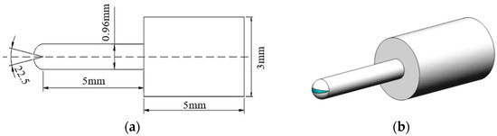
Figure 7.
Inner cavity model size of 0.48 mm equivalent diameter nozzle: (a) 0.48 mm equivalent nozzle internal cavity model size; (b) 0.48 mm equivalent nozzle internal cavity geometry model.
The flow field model of the nozzle cavity with an equivalent diameter of 0.48 mm is established. The airless spray nozzle is usually an elliptical (rugby ball shaped) nozzle outlet to spray a flat, approximately rectangular spray area, as shown in Figure 8a. In order to obtain the flow rate at the front spherical outlet in the numerical simulation, the front cut-out part needs to be included in the nozzle modelling and meshed uniformly. Considering the symmetry of the internal cavity structure of the nozzle, it is sufficient to model and mesh only a quarter of the nozzle in order to improve the calculation speed. Specifically, by modelling with Solidworks software, the actual angle of the front spherical cut-out is divided into lines at its spherical nozzle, and finally a one-quarter 3D geometric model of the nozzle inner cavity is obtained, as shown in Figure 8b.
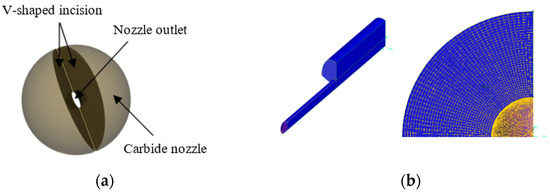
Figure 8.
Internal cavity structure and meshing: (a) Approximate rectangular spray area nozzle structure; (b) Equivalent nozzle internal cavity mesh division.
The boundary conditions are specified using a fan nozzle spraying model to virtually complete the spraying process, corresponding to the boundary divisions of pressure inlet, pressure outlet, wall boundary, and symmetry boundary. The spray atomisation fan area and the surrounding mesh are encrypted. For the solution of the problem of coupled motion of the discrete and continuous phases, the boundary conditions of the continuous phase are specified, while the boundary conditions of the discrete phase particles are also given when contact with the flow field boundary occurs.
(1) Under continuous phase boundary conditions, the inlet of the flow field boundary is designated as the velocity inlet, and the magnitude of its velocity value is determined by the velocity of the gun movement. The outlet of the flow field is set as a pressure outlet boundary, and the pressure is set to a standard atmospheric pressure, representing the free boundary of the flow field outlet. The surface being sprayed is set as a wall boundary condition and, to simulate the gun movement, the wall is designated as a moving wall, moving at the same speed as the air phase movement. The rest of the flow field boundary is far enough away from the gun range that a solid wall boundary is used, using no heat through and no velocity slip conditions.
(2) The following types of boundary conditions can be specified for discrete phase particles on collision with flow field boundaries. (a) Reflective boundaries—the particle will bounce back after colliding with this type of boundary with some loss of momentum; (b) trap boundary—when a particle collides with such a boundary, the calculation of the particle’s associated trajectory is terminated directly; (c) escape boundary—when a particle collides with a boundary, the calculation of the trajectory of the particle is terminated and no more information about the particle is counted; and (d) wall-film boundary—depending on the energy of the particle collision with the boundary and the temperature of the boundary, four scenarios will occur: adhesion, bounce, extension, and breakage. In order to calculate the deposition of paint on the wall, the surface to be painted is defined as the wall-film boundary. The entrance and exit of the flow field are defined as escape boundaries, which represent the disappearance of the particles after they have crossed.
For the solution of problems with coupled motion of the discrete and continuous phases, it is necessary to specify the boundary conditions not only for the continuous phase, but also for the discrete phase particles when they come into contact with the flow field boundary.
The numerical simulation model of this nozzle mainly involves four types of boundary conditions; the specific settings are shown in Table 3.
Table 3.
Setting of boundary conditions in numerical simulation model of nozzle.
Clicking on the models, the viscous models available in Fluent are: inviscid, laminar, Spalart–Allmaras single equation turbulence (SA), k-esilon (dual equation modelling), k-omega (dual equation modelling), transition k-kl-omega, transition SST, Reynolds stress model, scale adaptive model, Detached-Eddy Simulation (DES) turbulence model, and Large Eddy Simulation (LES). Factors to be considered when choosing a model are: the physical properties of the fluid, the simplicity of the problem, the accuracy of the calculation results, etc.
There is a range of suitability for each model; DES and LES finite element models are finely divided, have a large number of meshes, are computationally intensive, take a long time, and require a large amount of memory, so they are generally not used in practice; S-A turbulence models are generally used for solving problems with flows such as airfoil and wall boundary layers, while for jet-like problems such models are not suitable for solving; the standard k-ε turbulence model is highly stable and can be used for general turbulence problems with good accuracy and economy. The Realizable k-ε model has the advantage of keeping the Reynolds stress consistent with the real turbulent flow compared to the previous two k-ε models.
In this study, if paint is used as the fluid of study then viscous is chosen. The Edit Viscous Model dialog box appears, and although the Reynolds number of the flow in the inner cavity of this paper is small for laminar flow, the k-epsilon model is used for good convergence and small computational effort, and the RNG model is selected. The result of the setup is shown in Figure 9.
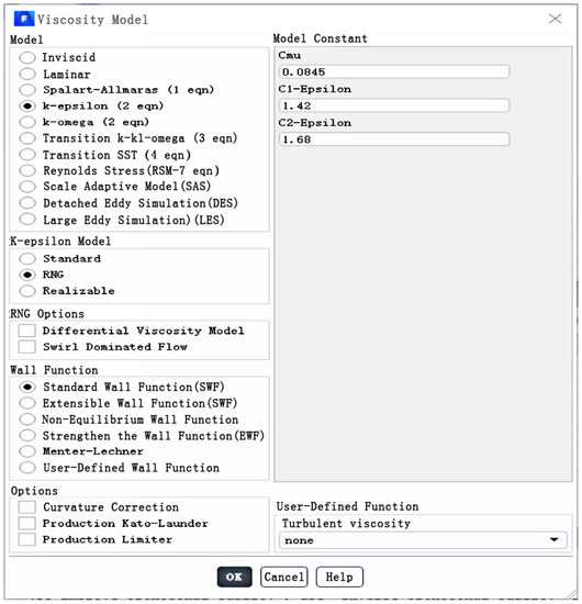
Figure 9.
Viscosity model selection dialog.
To edit the fluid material selection, we clicked on the material and created the fluid. The name defaults to air, so we changed air to youqi for easy identification. Then, we set the density and viscosity of the fluid. The density is known to be ρ = 1320 kg/m3 and the kinetic viscosity V = 0.275 kg/(m.s). The result is shown in Figure 10.
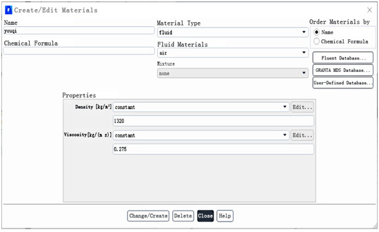
Figure 10.
Material settings dialog.
To check the unit area conditions, we clicked on fluid to make sure the material name is the same as the youqi just named.
Boundary condition setting: click on the entrance, edit the pressure entrance, because this paper simulation using pressure 6–20 MPa for analysis, the example using 8 MPa solution, converted into Pa to fill in the total pressure.The outlet is the pressure boundary condition, according to the default setting, and finally set the boundary condition of wall and symmetry boundary, here also choose the default setting. The pressure inlet settings are shown in Figure 11.
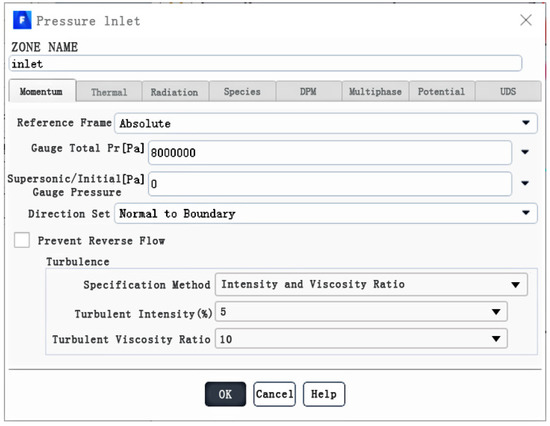
Figure 11.
Pressure inlet setting dialog.
The calculation process, using a steady-state calculation model, assumed that the density of paint coatings was 1320 kg/m3, viscosity was 0.275 kg/(m.s), and the surface tension was 0.036 n/m.
The experimental method: the paint used for spraying was epoxy resin paint from PPG Industries, USA. The hull surface paint was applied by mixing the topcoat base, hardener, and thinner in a certain ratio before spraying onto the hull surface. The mixing ratio is one barrel of topcoat base: one barrel of curing agent: 1/20 barrel of thinner, i.e.17.6:1.2:1. The paint material and worker operation are shown in Figure 12.
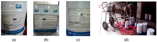
Figure 12.
Shipyard experimental paint and operation: (a) Topcoat base (SIGMADUR 550 BASE RAL 3000); (b) Hardener (SIGMADUR) 188/520/550; and (c) Thinner21-06 (AMERCOAT). (d) The worker is mixing three paints in proportion.
As the pressure range of the high-pressure airless spraying pump set is between 6 and 20 MPa, to prevent overload and remove the highest pressure of 20 MPa, the experiment was divided into seven groups, namely 6, 8, 10, 12, 14, 16 and 18 MPa. Each group was processed 10 times, a total of 70 times, and the average taken.
We prepared 70 scale fluid collection vessels on site, and conducted 70 paint collection experiments in seven groups.
We adjusted the pressure of the spray gun to 6, 8, 10, 12, 14, 16 and 18 MPa; each time, the paint sprayed by the spray gun was vertically aligned with the experimental fluid collection vessel, and sprayed for 1 min each instance. After the sample was collected, we allowed it to stand still for 1 h to ensure that all paint was deposited on the bottom of the vessel. Then, an ultrasonic sensor was used to measure the depth of the paint in the container and the volume converted. The average value of the difference in paint before and after the seven groups of experiments was the flow rate of paint sprayed per minute. After data processing, the experimental values of the shipyard were collected Table 4.
Table 4.
Error comparison between simulation and experiment.
It can be seen from the above table that the volume flow value obtained by simulation is relatively close to the experimental value, and the relative error is generally controlled within 8%. Therefore, it is feasible to use numerical simulation to simulate the flow field of the spraying equipment in the shipyard and analyse the jet flow mechanism of the spraying robot.
Therefore, next, the established model and the numerical simulation method can be further used to analyse the characteristics of the jet atomised particles.
3. Effect of Critical Weber Number on Atomisation Effect and Determination
A plane at different distances between the nozzle and the outer plate is selected as the monitoring surface. Seven layers of monitoring surfaces are selected, 0.02, 0.05, 0.09, 0.13, 0.17, 0.21, and 0.25 m from the nozzle.
3.1. Critical Weber Number versus Atomised Particle Diameter Variation
Different critical Weber numbers are selected for simulation as 6, 12 and 18, and the variation of coating particle diameter under different critical Weber numbers is obtained by simulation.
Different critical Weber numbers are selected for simulation as 6, 12, and 18, and the variation of coating particle diameter under different critical Weber numbers is obtained by simulation, as shown in Figure 13. Through the statistical analysis of the above particle information, the change in particle diameter can be drawn with the change in spraying distance curve, as shown in Figure 13.
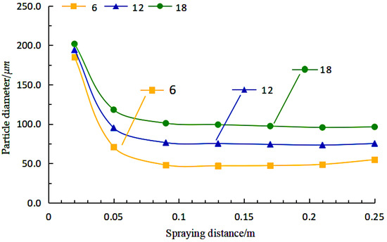
Figure 13.
Variation of particle diameter with spraying distance for different critical Weber numbers.
As can be seen from Figure 13, the nozzle aspect ratio of the particle diameter change trend is basically the same, the particles leaving the nozzle when the particle diameter decreases rapidly, but the droplet velocity change trend is different. After the atomisation is complete, the droplet diameter remains stable, no longer changing.
Atomisation process is mainly divided into two stages: the first stage of spraying distance is within 0.1 m; the paint droplet breakage mainly occurs in this area, at this time the droplet and the air phase relative speed is very large at the same time after the first atomization droplet diameter is also the largest; the second stage of spraying is mainly located in the area outside the spraying distance of 0.1 m, when the paint has been atomized completely, and the Weber number of droplets has been less than the critical Weber number of fragmentation. The paint in this stage mainly shows that the droplet speed is reduced, the diameter remains stable and the spraying range is gradually expanded. It can be seen that the Weber number is about large, the larger the particle diameter, so the more difficult to atomize.
3.2. Critical Weber Number of Atomised Particle Velocity Change Relationship
Assuming different Weber numbers of 6, 12 and 18 for the selected simulation, the simulation yields the spraying velocity of the paint particles under different critical Weber numbers, as shown in Figure 14. Figure 14 shows the rapid velocity of the paint drops, as high as 108 m/s, after leaving the nozzle. As the spraying distance increases, the droplets continue to exchange momentum with the air phase and the velocity decreases to 20–40 m/s when it reaches the vicinity of the wall. The velocity decay of the particles is directly influenced by the critical Weber number of fragmentation and is not influenced by the nozzle aspect ratio when the equivalent nozzle diameter is constant. As can be seen, the larger the critical Weber number, the greater the particle velocity, the more difficult the drops are to atomise.
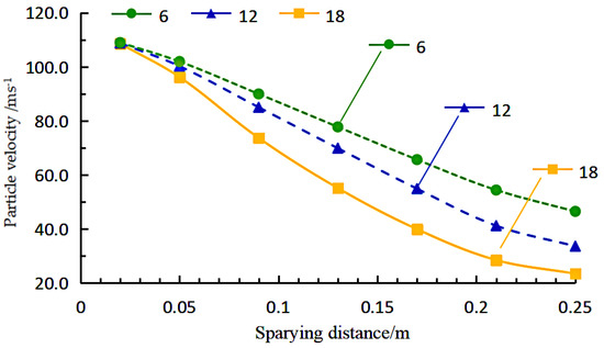
Figure 14.
Variation of particle velocity with spraying distance under different critical Weber numbers.
3.3. Determination of Critical Weber Number
The larger the critical Weber number, the more difficult it is to atomise the paint. In order to accurately simulate the atomisation effect, the critical Weber number parameter for the breaking of the paint is specified in the model at a spraying distance of 0.1 m, and the trend of particle diameter with velocity is plotted for different Weber numbers, as in Figure 15.
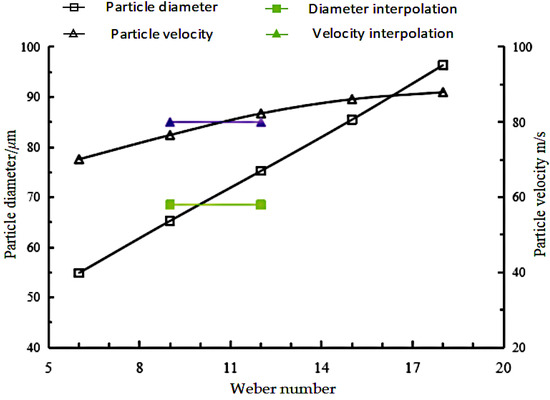
Figure 15.
Experimental interpolation to find the critical Weber Number.
The experimental value of the particle Sauter diameter is about 68.5 μm, interpolation in Figure 15, the critical Weber number is about 9.97, and the particle spraying speed near the axis at 100 mm is 80 m/s, the interpolation in Figure 15 can be calculated to get the critical Weber number is 10.7. Considering that the difference of 0.7 in the critical Weber number only leads to a difference of 2–3 μm in the atomization diameter, and the droplet velocity measurement is easily affected by the environment, and the experimentally obtained particle diameter is relatively accurate. Therefore, the critical Weber number of the broken paint is 9.97.
4. Analysis of Atomisation Effect
4.1. Effect of Atomisation Pressure on the Diameter of Atomised Particles
The atomisation diameters of the particles at different atomisation pressures are obtained by taking random pressure values between 1.5 MPa and 6.5 MPa. As the pressure increases, the atomisation diameter of the paint becomes smaller and smaller. The diameter of the droplets is largest when the paint particles first leave the nozzle and the liquid film is broken. This is followed by a secondary atomisation with the surrounding air, at which stage the number of small paint droplets gradually increases. After the secondary atomisation is complete, the droplet diameter remains stable and gradually spreads along the spraying diffusion angle over the entire spraying area.
The trend of the coating particle diameter at different pressures and different spraying distances is summarized in Figure 16. As can be seen from the curve, the curve down section that is the first stage of coating atomisation length is gradually lengthened with the increase in spraying pressure. When the atomisation pressure is 6 MPa, the length of the first stage of coating atomisation is only about 0.07 m, and when the pressure grows to 10 MPa, the atomisation area increases to about 0.1 m.
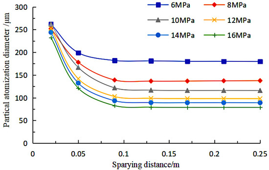
Figure 16.
Relationship between particle atomisation diameter and spraying distance and pressure.
The information of droplet diameter on the monitoring surface at the statistical spraying distance of 0.25 m is obtained to find the stable atomisation effect of the coating at different pressures, as shown in Figure 17.
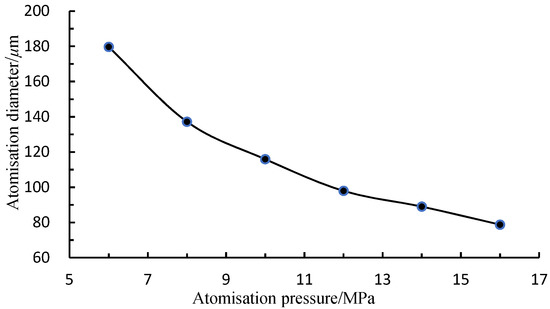
Figure 17.
The change curve of coating atomisation diameter with atomisation pressure.
With the increase in atomisation pressure, the droplet diameter in the fully atomised state decreases rapidly. The atomisation effect is more obviously affected by the atomisation pressure when the atomisation pressure is 6–10 MPa. When the atomisation pressure increases to more than 10 MPa, the atomisation diameter of the coating decreases at a slower rate by continuing to increase the atomisation pressure.
In order to more clearly analyse the change and distribution of particle diameter at different locations, statistics of particle diameter distribution within different monitoring surfaces are plotted to obtain information on particles at different locations under different pressures, and the scattering results of paint droplet diameter are shown in Figure 18, where D3,2 indicates the particle diameter and P indicates the spraying pressure.
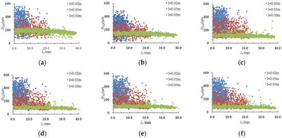
Figure 18.
Particle diameter dispersion under different atomisation pressure: (a) 6 MPa; (b) 8 MPa; (c) 10 MPa; (d) 12 MPa; (e) 14 MPa; and (f) 16 MPa.
The droplet particle diameter distribution of the paint formed at the completion of the initial atomisation is wide, and the droplet diameter distribution at 0.02 m monitoring surface from the nozzle ranges from 100 to 600 μm. With the spraying atomisation process, at 0.05 m monitoring surface can be found in the 400~600 μm particle size range of the paint, accounted for the reduction, indicating that in 0.02~0.05 m this range of large diameter droplets broke. When the particles reach the monitoring surface at 0.09 m from the nozzle, it can be found that the droplets above 200 μm break, with only a very small number of particles with a larger diameter.
The above phenomenon can be more clearly reflected by the standard deviation statistics of droplet diameter, and the standard deviation of droplets of different cross-sections is shown in Table 5.
Table 5.
Standard deviation of droplet diameter.
The distribution of particle diameter at 6–16 MPa is counted as shown in Figure 19. As the pressure increases, the diameter distribution of the atomised paint particles becomes more concentrated. The reason for this change is that increasing the atomisation pressure makes the kinetic energy of large particles increase, which makes it more difficult to maintain a stable form and thus tends to break into smaller droplets.
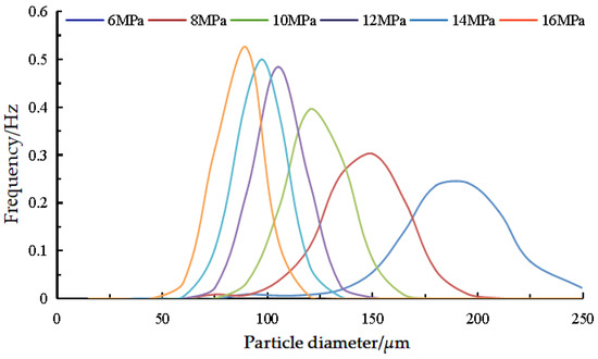
Figure 19.
Particle diameter distribution.
Figure 20 analyses the relationship between particle velocity and particle diameter for different pressures and spray distances of 0.05, 0.13 m, and 0.25 m, respectively.
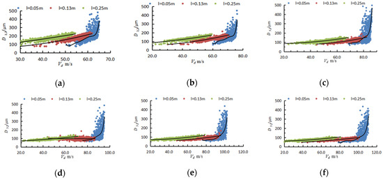
Figure 20.
Relation between droplet diameter and velocity in different spray pressure: (a) 6 MPa; (b) 8 MPa; (c) 10 MPa; (d) 12 MPa; (e) 14 MPa; and (f) 16 MPa.
The relationship between particle diameter and particle velocity at different pressures is generally consistent, as can be seen in Figure 20. At the 0.05 m cross-section, the fit reveals that the velocities of the larger diameter droplets are generally higher, while the velocities of the more thoroughly atomised droplets are more widely distributed and exist in all velocity intervals. At 0.13 m, the droplets are generally fully atomised and distributed across the velocity range, with only a few large diameter droplets that have not yet been atomised still having high velocities. The droplets with higher velocities at the 0.25 m cross section also have higher diameters.
4.2. Effect of Atomisation Particle Speed on Atomisation Effect
The velocity of the paint droplets affects the impact kinetic energy of the paint, therefore it is necessary to analyse the velocity of the atomised particles. The impact kinetic energy is related to the impact strength of the paint on the wall; too much speed will increase the kinetic energy of the paint, resulting in the paint colliding with the outer hull plate and then splashing, thus reducing the deposition rate, resulting in waste of paint and environmental pollution problems. The relationship between the axial velocity of the paint and the spray distance of the paint particles is shown in Figure 21.
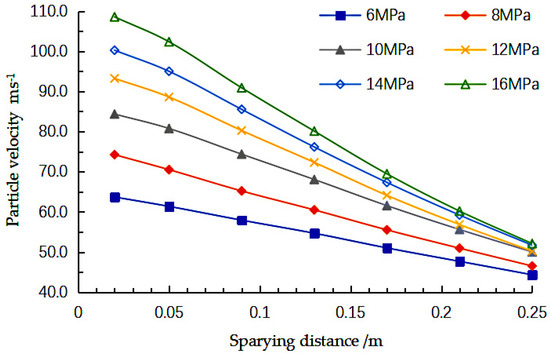
Figure 21.
Variation of particle velocity with spraying distance under different pressure.
The results of the calculation of the rate of change of the atomised particles are shown in Table 6.
Table 6.
Variation rate of droplet velocity.
4.3. Droplet Impact Kinetic Energy Analysis
Atomisation pressure will have a direct impact on the atomisation effect of the paint, including droplet diameter and speed, which in turn leads to a change in the impact kinetic energy E when the droplet touches the wall. The impact kinetic energy of a single droplet during the spraying process is more obvious compared with the change in droplet diameter and speed. Droplet kinetic energy and spraying distance and the relationship between the spraying pressure is shown in Table 7.
Table 7.
Variation rate of droplet impact kinetic energy E.
As the atomisation pressure increases, the kinetic energy loss of droplets at the end stage of spraying increases significantly, and when the pressure increases to more than 10 MPa, the impact kinetic energy loss ratio of single droplets reaches more than 95%, indicating that the atomisation process is very intense. The impact kinetic energy at the moment of coating to the outer plate is inversely proportional to the deposition rate of the coating. We studied the distribution of droplet impact kinetic energy at a spraying distance of 0.25 m under 16 MPa pressure, and drew the droplet kinetic energy distribution and its fitted surface as shown in Figure 22, where E indicates the droplet impact kinetic energy. It can be seen that when the paint is near the surface of the outer plate, the impact kinetic energy of the paint is higher in the middle part of the spraying rectangle.
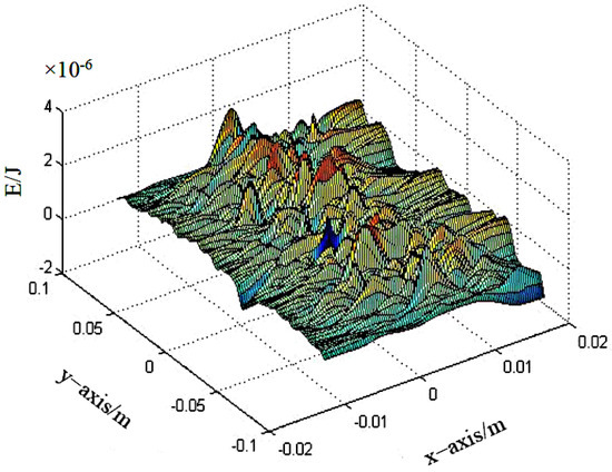
Figure 22.
Coating impact kinetic energy E distribution.
Figure 23 shows the fitting curve of the radial distribution of the impact kinetic energy of the coating within the monitoring surface of 0.25 m.
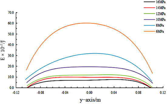
Figure 23.
Fitting curve of kinetic energy E radial distribution of paint.
Figure 24 shows the fitting curve of the direction distribution of the vertical spraying sector.
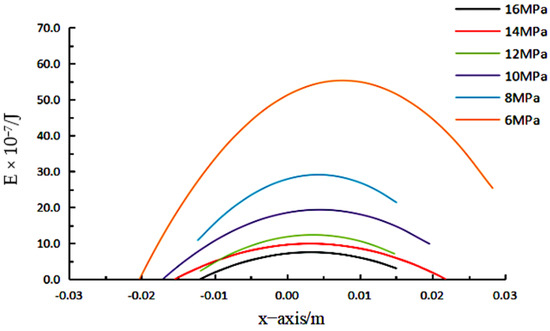
Figure 24.
Directional kinetic energy E distribution fitting curve.
As shown in Figure 24, the impact kinetic energy of the coating sprayed on the outer plate gradually decreases with the increase in spraying pressure, and at the same time, the decrease rate of the impact kinetic energy of the droplets also slows down. Combined with the collision fracture model, the theoretical spraying deposition rate increases gradually with the increase in atomising pressure. The droplet impact kinetic energy distribution is radial symmetric, and the impact kinetic energy is large near the axis and low near the edge of the spraying area. No deviation occurs in the fitting, indicating that the droplet distribution is affected very little by gravity in the spraying atomisation process. When the spraying pressure is below 10 MPa, the impact kinetic energy of the coating gradually decreases along the radial direction from the axis to both sides. When the spraying pressure is above 10 MPa, the droplet impact kinetic energy in the vicinity of the axis remains consistent, and then decreases at the edge of the spraying area.
The impact kinetic energy distribution of the paint in the direction of the vertical spraying sector is counted, and the effect of pressure on the impact kinetic energy is the same as in the sector range. The difference is that the impact kinetic energy distribution of the paint is no longer symmetrical with respect to the axis, a clear shift in kinetic energy distribution can be found along the direction, and the lower the pressure the more obvious the shift in the kinetic energy of the paint. The analysis suggests that this is due to the effect of the droplet shift caused by the gun movement, as it is in the same direction as the spraying direction, so this part of the kinetic energy shift does not have a significant effect on the paint deposition effect.
4.4. Effect of Atomisation Pressure on Deposition Rate
The results of calculating the coating deposition rate at different spraying pressures at a spraying speed of 0.5 m/s, while comparing the atomised spraying diffusion angle of 45° and 60°, are shown in Figure 25.
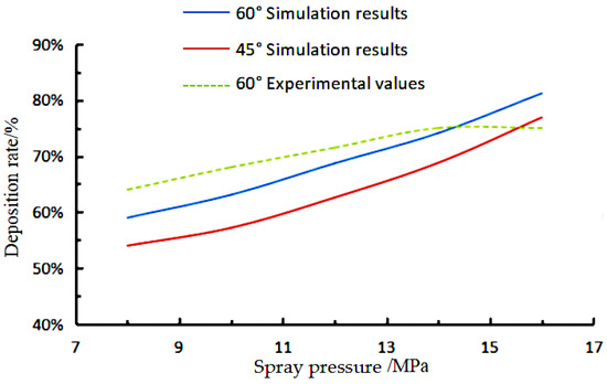
Figure 25.
Relation between paint deposition rate and spray pressure.
As the atomisation pressure increases, there is a significant increase in the deposition rate of the paint, which rapidly rises from approximately 60% to around 80%. This is consistent with the analysis of the change in the kinetic energy of the paint droplets above. By varying the diffusion angle of the atomised spray, it can be found that increasing the diffusion angle also helps to increase the deposition rate of the paint.
4.5. Liquid Film Thickness Growth Analysis
According to the principle of film thickness growth, on the one hand, the reason is that the spraying mass flow of paint increases rapidly with the increase in spraying pressure. On the other hand, the deposition rate of paint also increases with the increase in spraying pressure, and the distribution of the film thickness of paint shows the law of high and low in the middle on both sides. It can be found that the film thickness is relatively low in the middle of the spraying area, and the film thickness is thicker at the edge of the spraying rectangle.
According to the paint collision breakage model, when the impact kinetic energy of paint is greater than the critical impact kinetic energy, the deposition rate of paint will gradually decrease with the increase in impact kinetic energy. So, according to the droplet impact kinetic energy analysis, it can be concluded that the coating deposition rate is low near the axis within the spraying sector, and the coating deposition rate will increase significantly near the outside of the spraying sector. The comprehensive analysis shows that the thickness of the paint, i.e., the deposition rate, increases as the spraying pressure increases.
In order to study the distribution of the liquid film thickness in the spraying area, the liquid film thickness of the nodes in the spraying rectangular area is extracted, and the relationship curve between the liquid film thickness and the distance from the axis is drawn. The results are shown in Figure 26.
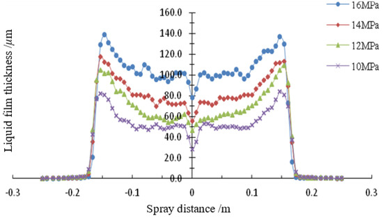
Figure 26.
Variation curve of liquid film thickness with distance from the axis.
With the increase of spraying pressure, the growth pattern of the liquid film thickness formed by spraying remains consistent. On the one hand, it is because the spraying mass flow of the coating increases rapidly with the increase of the spraying pressure, on the other hand, the deposition rate of the coating also increases with the increase of the spraying pressure, and the combined effect of both causes the thickness of the coating to increase with the increase of the spraying pressure. At the same time, the distribution of the coating film thickness shows the law of high on both sides and low in the middle, and it can be found that the film thickness is relatively low in the middle of the spraying area, and the film thickness is thicker at the edge of the spraying rectangle.
Figure 27 shows the liquid film thickness distribution on the outer plate at the spraying distance of 0.3 m at 16 MPa. The kinetic energy distribution of liquid droplets in the monitoring surface and its fitting curve through 0.25 m from the nozzle are plotted. It can be seen that, within the range of ±0.1 m from the axis, the kinetic energy of droplets and the distribution of liquid film thickness is basically flat, and in the range beyond ±0.1 m from the axis, with the kinetic energy of droplets impacting on the edge of the spraying sector decreases; the liquid film thickness correspondingly shows a rising trend. Therefore, it can be seen that the film thickness and the kinetic energy of the droplet show an inverse correlation.
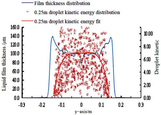
Figure 27.
Comparison of liquid film thickness and droplet kinetic energy distribution.
According to the paint collision fragmentation model, when the impact kinetic energy of paint is greater than the critical impact kinetic energy, the deposition rate of paint will gradually decrease with the increase in impact kinetic energy. So, according to the droplet impact kinetic energy analysis, we can conclude that the coating deposition rate is low near the axis within the spraying sector, and there will be a significant increase in the coating deposition rate near the outside of the spraying sector.
5. Conclusions
This paper establishes a mathematical model of the cavity flow of the fan nozzle, a mathematical model of jet atomisation, and a simplified physical model of the equivalent entity, and uses a 0.48 calibre nozzle as a case study to simulate the spraying flow rate at different spraying pressures to explore the evaluation index of atomisation characteristics. We also analysed the effect of the critical Weber number on the atomised particle diameter and movement speed; determined the critical Weber number; and simulated the effect of atomisation pressure on the atomised particle diameter, movement speed, impact kinetic energy, deposition rate, and film growth. The following results were obtained from the simulation of the effect of atomisation pressure on atomised particle diameter, motion speed, impact kinetic energy, deposition rate, and liquid film growth.
(1) The larger the critical Weber number, the more difficult the paint atomisation. According to the interpolation analysis of the experimental results, we set the critical Weber number of 9.97. With the increase in pressure, the atomisation diameter of the paint particles decreases; with the increase in atomisation pressure, the atomisation speed of the paint particles increases; with the increase in atomisation pressure, the collision kinetic energy of the paint particles increases. This means that, as the atomisation pressure increases, the atomisation effect of the paint becomes better.
(2) As the atomisation distance increases, the droplet impact kinetic energy decreases. Comparing the droplet impact kinetic energy distribution with the liquid film thickness distribution, we found that the paint impact kinetic energy is directly related to the paint deposition effect; the lower the droplet impact kinetic energy upon reaching the surface of the outer plate of the ship, the higher the transfer rate of the paint. The overall liquid film thickness distribution shows the phenomenon of a spraying rectangle with thick sides and thin centre. With the increase in atomisation pressure, the coating thickness increases; therefore, the better the atomised particle spraying adhesion deposition rate of the paint, the better the overall spraying effect.
(3) Through the atomisation analysis of the modelling and simulation of high pressure airless spraying on the outer hull plate, it is recommended that in the design process of developing the spraying robot for the outer hull plate, the spraying distance between the spray gun and the outer hull plate should be controlled, the spraying trajectory and walking route of the robot should be adapted to the linear shape of the outer hull plate, and the control of the instantaneous impact kinetic energy should be paid attention to during the operation of the robot firing gun.
Author Contributions
The manuscript is written through contributions of all authors. Conceptualization, Z.Y.; methodology, Z.Y.; software, B.F. and T.T.; validation, B.F.; formal analysis, Z.Y. and K.L.; investigation, T.T.; resources, Z.Y. and B.L.; data curation, Z.Y.; writing—original draft preparation, S.M.; writing—review and editing, S.M.; supervision, Z.Y. and Y.L.; project administration, Z.Y.; and funding acquisition, Z.Y. All authors have read and agreed to the published version of the manuscript.
Funding
This work is supported by the Projects Funded by the Central Government to Guide Local Scientific and Technological Development (Grant No. 2021JH6/10500156) and the Key Laboratory of Environment Controlled Aquaculture, Ministry of Education (Grant No. 2021-MOEKLECA-KF-07) and the Program Funded by Liaoning Province Education Administration (Grant No. 100920202037).
Institutional Review Board Statement
Not applicable for studies not involving humans or animals.
Informed Consent Statement
Not applicable.
Data Availability Statement
Not applicable.
Conflicts of Interest
The authors declare no conflict of interest.
References
- Buketov, A.; Maruschak, P.; Sapronov, O.; Zinchenko, D.; Yatsyuk, V.; Panin, S. Enhancing Performance Characteristics of Equipment of Sea and River Transport by Using Epoxy Composites. Transport 2016, 31, 333–342. [Google Scholar] [CrossRef] [Green Version]
- Buketov, A.; Smetankin, S.; Maruschak, P.; Yurenin, K.; Sapronov, O.; Matvyeyev, V.; Menou, A. New Black-Filled Epoxy Coatings for Repairing Surface of Equipment of Marine Ships. Transport 2020, 35, 679–690. [Google Scholar] [CrossRef]
- Bobbie, M.M.; Peter, J.C. Supramolecules. In Supramolecular Chemistry in Corrosion and Biofouling Protection, 5th ed.; Saji, V.S., Ed.; CRC Press: Boca Raton, FL, USA, 2021; p. 14. [Google Scholar]
- Rein, M. Phenomena of Liquid Drop Impact on Solid and Liquid Surfaces. Fluid Dyn. Res. 1993, 12, 61–93. [Google Scholar] [CrossRef]
- Plesniak, M.W.; Sojka, P.E.; Singh, A.K. Transfer efficiency for airless painting systems. JCT Res. 2004, 1, 137–145. [Google Scholar] [CrossRef]
- Nijemeisland, M.; Dixon, A.G. CFD study of fluid flow and wall heat transfer in a fixed bed of spheres. AIChE J. 2004, 50, 906–921. [Google Scholar] [CrossRef]
- Jepsen, R.A.; Yoon, S.S.; Demosthenous, B. Effects of air on splashing during a large droplet impact: Experimental and numerical investigations. At. Sprays 2006, 16, 981–996. [Google Scholar] [CrossRef]
- Liu, J.; Vu, H.; Yoon, S.S.; Jepsen, R.; Aguilar, G. Splashing Phenomena During Liquid Droplet Impact. At. Sprays 2010, 20, 297–310. [Google Scholar] [CrossRef] [Green Version]
- Ye, Q.; Shen, B.; Tiedje, O.; Domnick, J. Investigations of Spray Painting Processes Using an Airless Spray Gun. Energy Power Eng. 2013, 7, 74–81. [Google Scholar]
- Mark, A.; Andersson, B.; Tafuri, S.; Engstrom, K.; Sorod, H.; Edelvik, F.; Carlson, J.S. Simulation of Electrostatic Rotary Bell Spray Painting in Automotive Paint Shops. At. Sprays 2013, 23, 25–45. [Google Scholar] [CrossRef] [Green Version]
- Andulkar, M.V.; Chiddarwar, S.S.; Maearhe, A.S. Novel integrated offline trajectory generation approach for robot assisted spray painting operation. J. Manuf. Syst. 2015, 55, 201–208. [Google Scholar] [CrossRef]
- Bobzin, K.; Wietheger, W.; Knoch, M.A. Development of Thermal Spray Processes for Depositing Coatings on Thermoplastics. J. Therm. Spray Technol. 2021, 30, 157–167. [Google Scholar] [CrossRef]
- Abbas, M.; Buntinx, M.; Deferme, W. Comparison of the oxygen gas and UV barrier properties of Nano-ZnO-Coated PET and PHBHHx packaging fifilms via ultrasonic spray coating. In Proceedings of the Nanotech France 2019 International Conference, Paris, France, 26–28 June 2019. [Google Scholar]
- Abbas, M.; Buntinx, M.; Deferme, W.; Reddy, N.; Peeters, R. Oxygen Gas and UV Barrier Properties of Nano-ZnO-Coated PET and PHBHHx Materials Fabricated by Ultrasonic Spray-Coating Technique. Nanomaterials 2021, 11, 449. [Google Scholar] [CrossRef] [PubMed]
- Zhu, L.S.; Cao, J.C. High-pressure airless spraying equipment and its development. Paint. Corros. 1997, 31–33, 47. [Google Scholar]
- Teng, Y.; Wang, X.; Sun, Z.S. Experimental Research on Atomizing Characteristics of Paint for High-pressure Airless. Surf. Technol. 2011, 40, 68–70. [Google Scholar]
- Kang, J.; Luo, J.; Gong, W.J. Numerical Simulation of Internal Low Field on Hyperbaric Non-gas Spraying Nozzl. Chongqing Univ. Technol. 2013, 27, 34–38. [Google Scholar]
- Wang, S.Y.; Zhang, W.; Jiang, J.B. Research of plywood airless atomization nozzle simulation and analysis. Wood Processing Mach. 2013, 5, 34–36. [Google Scholar]
- Yin, S.; Wang, X.F.; Li, W.Y. Numerical Investigations on the Effect of Nozzle Outlet Diameteron Jet Flow Field and Optimal Stand off Distance in Cold Spraying. China Surf. Eng. 2013, 26, 74–78. [Google Scholar]
- Xu, X.M. Simulation and Optimum Design of Container Automatic Spraying. Master’s Thesis, South China University of Technology, Guangzhou, China, 2015. [Google Scholar]
- Zhang, Y.; Zhang, X.; Zheng, J. Jet characteristic of supersonic plasma spraying. Mater. Sci. Eng. Powder Metall. 2017, 22, 713–718. [Google Scholar]
- Sun, Y.; Zhao, M.; Xia, H.B. Numerical Simulation of Internal Flow Field of Fan-Shaped Nozzle Used for High-Pressure Airless Spraying Putty. J. Dalian Jiaotong Univ. 2018, 35, 42–46. [Google Scholar]
- Yi, Z.; Song, C.; Zhang, G.; Tong, T.; Ma, G.; Wu, D. Microstructure and Wear Property of ZrO2-Added NiCrAlY Prepared by Ultrasonic-Assisted Direct Laser Deposition. Materials 2021, 14, 5785. [Google Scholar] [CrossRef] [PubMed]
- Xie, T.H.; Gao, C.S.; Guo, C. Experimental Research on Abrasive Water Jet Drilling of APS Ceramic Thermal Barrier Coating. J. Nanjing Univ. Aeronaut. Astronaut. 2020, 52, 792–799. [Google Scholar]
Publisher’s Note: MDPI stays neutral with regard to jurisdictional claims in published maps and institutional affiliations. |
© 2022 by the authors. Licensee MDPI, Basel, Switzerland. This article is an open access article distributed under the terms and conditions of the Creative Commons Attribution (CC BY) license (https://creativecommons.org/licenses/by/4.0/).