Abstract
In this paper, solution precursor plasma spraying (SPPS) was employed to prepare a porous YSZ/LSM composite cathode for solid oxide fuel cell (SOFC). The surface morphology and microstructure of the composite cathode deposits were characterized using SEM. The effect of annealing treatment on SPPS YSZ/LSM microstructure was examined. The results showed that the as-sprayed YSZ/LSM deposits presented a porous aggregate with a size range of 10–60 μm when the alcohol was used as the solvent and the spraying distance was 60 mm. The porous aggregate was found to be composed mainly of small particles ranging from 0.2–2 μm, the YSZ/LSM composite cathode showed a finely porous microstructure with grain sizes from micrometers to sub-micrometers. A further annealing treatment at 1050 °C for 2 h in air resulted in a continuous microstructure porous coating with a perovskite phase. The polarization test results demonstrated that the minimum polarizations were 1.26 and 0.083 Ω·cm2 for the composite cathode at 800 and 1000 °C, respectively.
1. Introduction
Solid oxide fuel cells (SOFCs) are highly efficient chemical fuel cells, which have been widely used in submarines [1], automobiles [2], aircraft [3], and other fields [4]. The successful application of this technology is of great significance for alleviating the energy crisis and protecting the ecological environment [5]. However, in the process of commercializing solid oxide fuel cells, the high manufacturing cost of SOFC power generation systems, low output power density, and low long-term stability of the cell stack have become the main obstacles to their large-scale commercial development [6,7,8].
In recent years, many studies have focused on the materials [9,10,11], the preparation process [12,13], and the structure optimization [14,15,16] of SOFC power generation systems to establish a competitive SOFC system compared with the existing power generation technology. In SOFC power generation systems, one method of saving costs is to reduce the operating temperature. However, as the operating temperature decreases, the electrochemical performance of the SOFC also decreases, which is mainly due to the increase in the polarization resistance of the electrodes and the decrease in the conductivity of the electrolyte [17].
While, with the thinning of electrolytes, the wide application of new electrolyte materials in SOFC, and the optimization of the anode structure, cathode polarization has become the main bottleneck restricting the power output of batteries [18,19,20]. Therefore, the focus of attention has transferred from the electrolyte to the cathode. Recently, many new cathode materials have been evolved and shown high catalytic activity [12,21]; however, their long-term stability is still a challenge to overcome.
When it comes to long-term stability, the traditional Y2O3-stabilized ZrO2/La1−xSrxMnO3 (YSZ/LSM) material system has its advantages and therefore attracts special research interest as one of the solutions to commercialize SOFC [22,23]. Solution precursor plasma spraying (SPPS), an easy and low-cost process, has the potential to prepare coatings with submicron or nanoscale porous structures [24,25].
According to our previous studies [26,27], La0.8Sr0.2MnO3 (LSM) cathodes have been successfully fabricated using SPPS. However, the polarization properties still need to be improved. In an earlier report, Prakash et al. [28] prepared LSM/YSZ-based solid oxide fuel cell cathodes by SPPS; however, the effect of an annealing treatment on the surface morphology of YSZ/LSM was not considered in that study. In addition, the microstructure and polarization properties of YSZ/LSM composite cathodes and the single LSM cathode prepared by SPPS were also not investigated systematically.
Herein, the traditional YSZ/LSM composite cathode was prepared by solution precursor plasma spraying. The microstructure control law of YSZ/LSM composite cathode and its structure–activity relationship with performance were clarified to establish a low-cost preparation method of the high-performance cathode. The microscopic morphology and polarization properties of YSZ/LSM were compared with those of a single LSM cathode prepared by the plasma spraying of solution precursors to provide an effective way of solving the current commercial development of SOFC.
2. Materials and Methods
2.1. Materials
The nominal compositions of the YSZ and LSM in this paper were 0.08 mol Y2O3-stabilized ZrO2 and La0.8Sr0.2MnO3, respectively. The molar ratio of YSZ and LSM in the YSZ/LSM composite cathode was 1:1. In a typical preparation, 0.16 mol Y(NO3)3 × 6H2O, 1 mol Zr(NO3)4 × 5H2O, 0.8 mol La(NO3)3 × 6H2O, 0.2 mol Sr(NO3)2, and 1 mol Mn(NO3)3 (solution, 50 wt.%) were dissolved in distilled water. The raw materials used in the experiment were obtained from Sinopharm Chemical Reagent Co., Ltd. (Shanghai, China). After adding an appropriate amount of absolute ethanol, the mixture was stirred with a magnetic stirrer until obtaining a uniform solution. The amount of ethanol added should ensure that the concentration of nitrate ions in the solution is 0.1 mol/L. The as-obtained solution was used as a spraying precursor solution. A molded YSZ ceramic sheet was used as substrate material, with a thickness of about 1 mm and a diameter of about 20 mm. Before spraying, the substrate surface was ground and polished.
2.2. Preparation and Characterization of YSZ/LSM Composite Cathode
The YSZ/LSM composite cathode was sprayed by SPPS technology. The surface and cross-sectional morphology of the YSZ/LSM cathode coating was observed by scanning electron microscope (SEM, VEGA II-XMU, TSCAN, Brno, Czech Republic), the phase structure was characterized by X-ray diffraction (XRD, Rigaku D/max-2400, Tokyo, Japan), and the porous structure and thickness of the coating were analyzed by an imaging method. The SPPS deposition system was composed mainly of a traditional plasma spray gun and a liquid feeding system.
The plasma spraying equipment was an XM-80SK high-energy plasma spraying system manufactured by Shanghai Xiuma Spraying Machinery Co., Ltd. (Shanghai, China). The liquid material can be fed into the plasma flame by a peristaltic pump through a small hole with a diameter of 0.4 mm in the nozzle. In the experiment, Ar was used as the main gas and H2 as the auxiliary gas. The arc power used to generate the plasma jet in this experiment was 36 kW (60 V × 600 A), the pressure and flow rates of Ar were 0.8 MPa and 40 L/min, and the pressure and flow rates of H2 were 0.4 MPa and 30 L/min, respectively as shown in Table 1.

Table 1.
The SPPS spraying process parameters.
During the spraying process, the spray gun was fixed on the manipulator, and the spraying distance and the moving speed of the spray gun can be controlled by the manipulator. To prepare a circular composite cathode with a diameter of 6.5 mm, a mask with an opening diameter of 6.5 mm was used to cover the YSZ substrate, and the axis of the plasma spray gun was adjusted to align with the center of the mask. To increase the adhesive strength between the deposited particles and the substrate, prior to the spraying process, the backside of the substrate was heated slowly by a flame gun, and an infrared thermometer was employed to measure the surface temperature of the substrate. Coating deposition began when the substrate temperature reached 400 °C.
2.3. Characterization of Polarization Properties of Composite Cathode
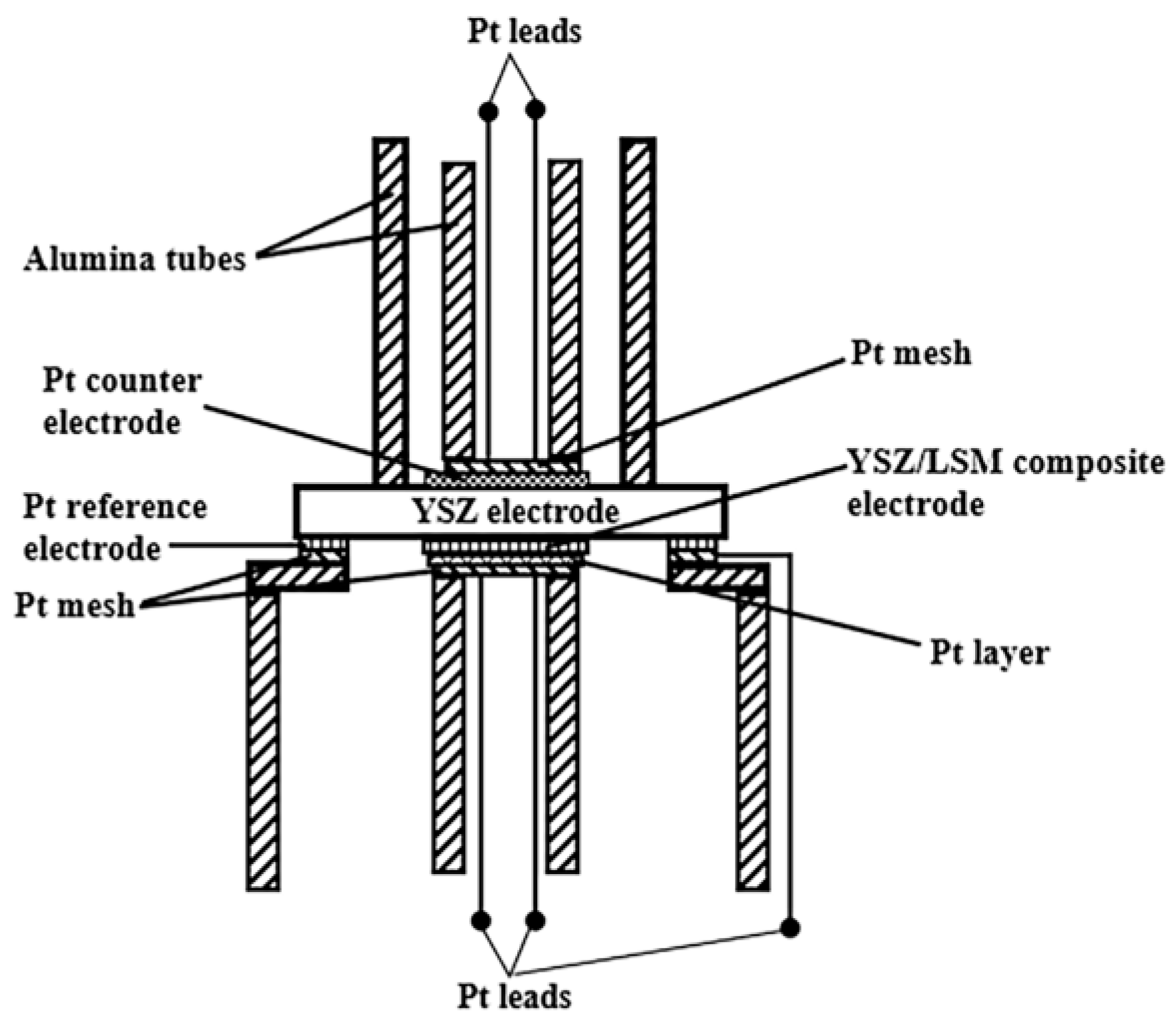
Figure 1 shows a schematic diagram of the polarization test device. The geometrical area of the porous YSZ/LSM composite cathode was 0.33 cm2. As the counter electrode, Pt paste was painted symmetrically to the composite cathode on the opposite side of the electrolyte pellet. As the reference electrode, a Pt paste with a width of 2 mm was painted at the perimeter of the pellet. Reference and counter electrodes were fixed to the pellet through firing at 850 °C for 0.5 h.

Figure 1.
Schematic diagram of the polarization resistance test device.
The distance between Pt reference electrode and composite cathode was about 5 mm. The impedance measurements were conducted in air from 800 to 1000 °C at an interval of 50 °C. A frequency response analyzer (Solartron1260) and an electrochemical interface (Solartron 1287, Solartron analytical, Hampshire, UK) were used for the electrochemical impedance measurements. The tests were performed in a frequency range from 0.1 to 105 Hz with the amplitude of the AC signal of 100 mV at equilibrium potential. The three electrode configuration and test approach was proposed in the reference [29] in detail.
3. Results and Discussion
3.1. Phase Structure of YSZ/LSM Deposits
In SPPS, metal nitrates were used as the raw materials for the starting precursor. During deposition, the droplets injected into the plasma jet will undergo rapid solvent evaporation, solute precipitation, decomposition, chemical reaction and synthesis, melting, solidification, and crystallization. Then, these particles are collected to form a deposit. The X-ray diffraction patterns of the YSZ/LSM composite deposits are shown in Figure 2. We observed that the as-sprayed deposit presented a partially crystallized phase.
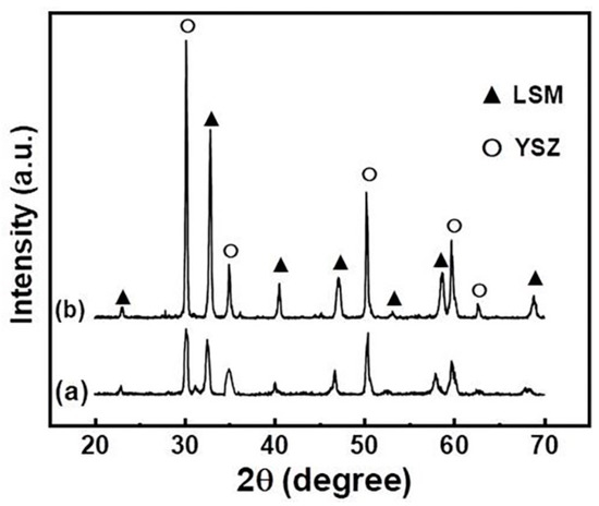
Figure 2.
XRD pattern of YSZ/LSM deposits: (a) as-sprayed and (b) after annealing at 1050 °C for 2 h in air.
Although the temperature of the plasma flame is very high, the dwelling time of droplets in the plasma jet is very short [30]. If the droplet dwells for insufficient time within the plasma flame or passes through the periphery of the plasma jet, incomplete evaporation of the solvent and condensation of the precursor materials occurs; this will result in incomplete crystallization. After annealing in air at 1050 °C for 2 h, complete crystallization to the desirable phase was observed, which is evident from the increased XRD peak intensity of the annealed sample.
3.2. Microstructure of YSZ/LSM Prepared by SPPS
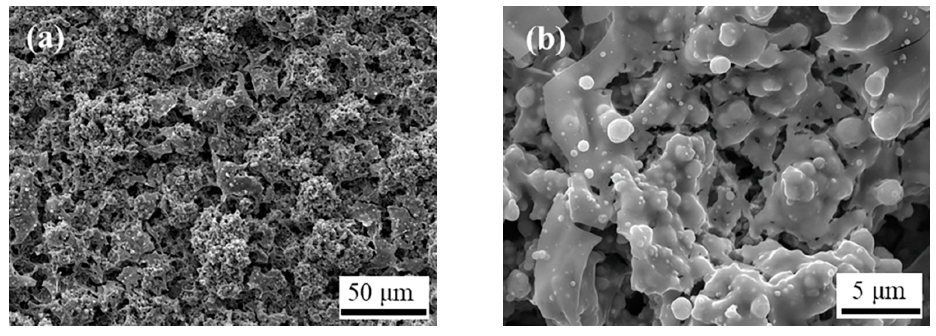
Figure 3 shows the surface morphology of YSZ/LSM prepared by SPPS with a spraying distance of 60 mm. From Figure 3a, the deposited particles present aggregates with sizes ranging from 10 to 60 µm. It can be inferred that each agglomerate corresponds to a large droplet in the plasma flame. These agglomerates have a loose and porous structure, with large pores between the agglomerates.

Figure 3.
The surface morphology of YSZ/LSM prepared by ethanol SPPS at a spraying distance of 60 mm: (a) Low magnification. (b) High magnification.
From the higher magnification of the surface, as shown in Figure 3b, the deposited agglomerates are composed of small particles of 0.2–1.5 µm, which can help to increase the triple phase boundaries (TPB) length of the cathode, thereby, reducing the polarization resistance. The polarization of the cathode is related to the length of the TPB, Deng et al. [31] established a calculation model for the length of the TPB in SOFC, and the various influencing factors on its length were also simulated and calculated. Under the condition of constant porosity, the length of the TPB increased with decreasing particle size, resulting in smaller polarization resistance.
3.3. Effect of Annealing Treatment on the Microstructure of YSZ/LSM Composite Cathode
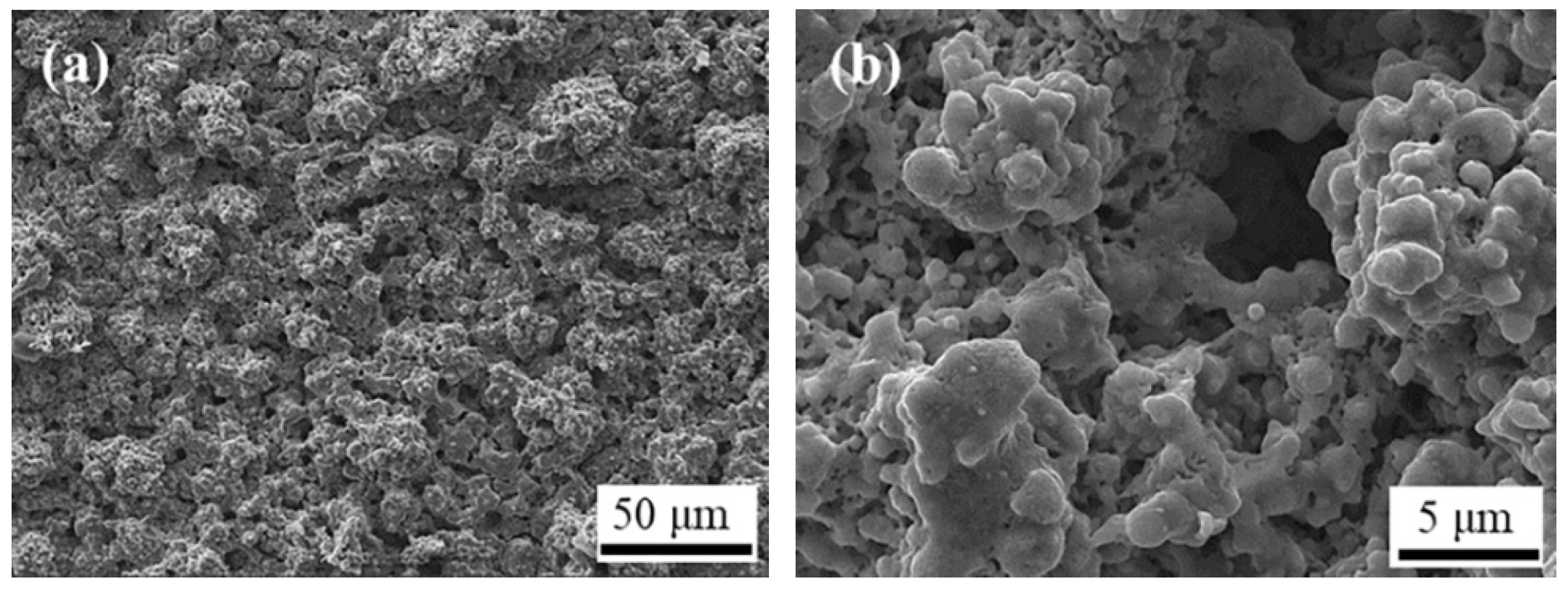
Figure 4 shows the surface morphology of the YSZ/LSM composite cathode prepared by SPPS after annealing treatment at 1050 °C for 2 h in air. Compared with the surface morphology of the untreated sample, the surface edges and corners of the large agglomerates of the heat-treated sample became smaller, as shown in Figure 4a, while the small particles in the agglomerates were almost the same for both samples, as shown in Figure 3b and Figure 4b.

Figure 4.
Surface morphology of the YSZ/LSM composite cathode after annealing treatment at 1050 °C for 2 h: (a) Low magnification. (b) High magnification.
This indicates that the microstructure of the sprayed YSZ/LSM deposits remained stable during the annealing treatment process, and there was no obvious particle sintering and growth phenomenon. This feature indicates that the YSZ/LSM composite cathode would exhibit good structural stability under high temperature operating conditions.
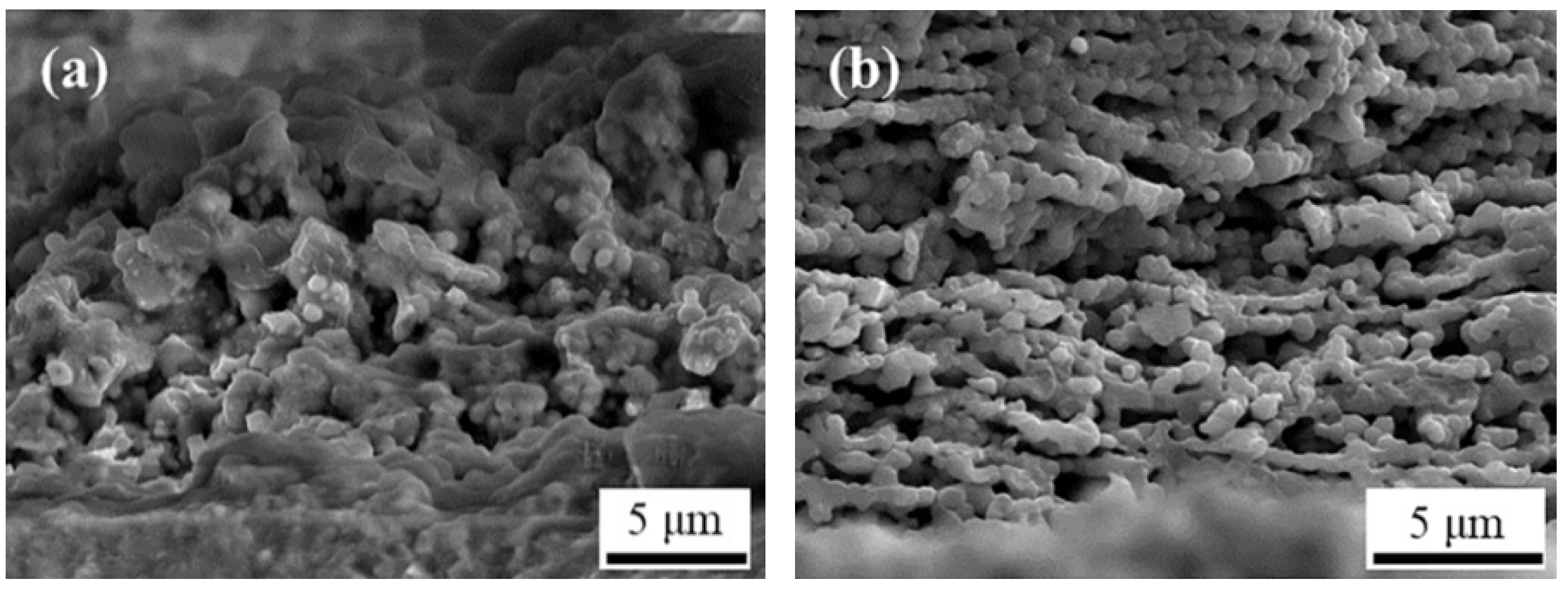
Figure 5a shows the as-sprayed cross-sectional morphology of the YSZ/LSM cathode prepared by SPPS. The YSZ/LSM showed a porous structure with a thickness of about 40 µm; however, the layered structure features of LSM prepared by plasma spraying of aqueous precursors were not observed [26,27] as shown in Figure 5b.

Figure 5.
The as-sprayed cross-sectional morphology of the YSZ/LSM cathode and LSM cathode prepared by ethanol SPPS: (a) YSZ/LSM cathode. (b) LSM cathode.
Figure 6 shows the cross-sectional morphology of the YSZ/LSM cathode prepared by SPPS after annealing treatment at 1050 °C for 2 h. From Figure 6a,b, the cross-sectional structure of the coating after annealing treatment was not greatly different from that of the untreated coating. The YSZ/LSM cathode after annealing treatment was mainly composed of agglomerates containing spherical particles.
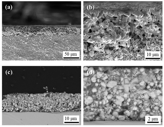
Figure 6.
The cross-sectional morphology of the SPPS YSZ/LSM cathode after annealing treatment: (a,b) As-sprayed: (a) Low magnification. (b) High magnification. (c,d) Impregnating and polishing: (c) Low magnification. (d) High magnification.
The agglomerates had a porous structures with micron to submicron and even nanometer scales. In order to obtain a clearer view of the porous structure, the YSZ/LSM cathode was impregnated with commercial E-7 glue, and then the polished section was prepared after the pores were immobilized. It can be seen, from Figure 6c,d, that there were large pores between some of the large agglomerates, and most of the pores were between 0.2 to 2 µm in size.
3.4. The Electrochemical Performance of YSZ/LSM Composite Cathode
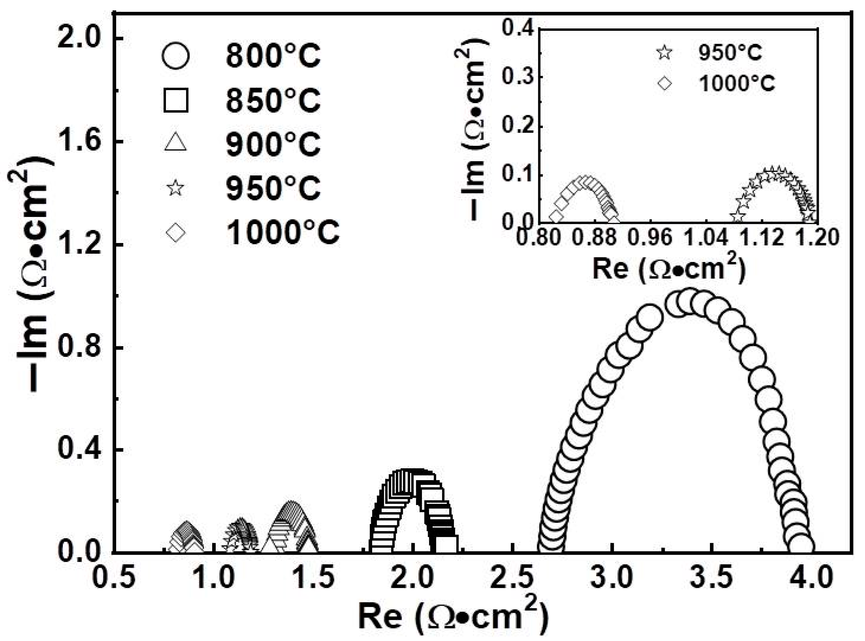
The polarization resistance properties of the cathode were tested using the AC impedance method. Figure 7 shows the Nyquist diagrams of the YSZ/LSM cathode after annealing at 1050 °C for 2 h, which were tested at 800–1000 °C. Each curve intercepted the real axis at a low and a high frequency, respectively. The high frequency intercept R0 is the overall ohmic resistances, including the YSZ ionic resistance, LSM electronic resistance, contact resistance between the electrode and Pt mesh, and external cell connection resistance. The intercept difference between the low and high frequency of the semicircle represents the cathode polarization Rp, as shown in Figure 7. The polarization resistance decreases between the electrolyte and electrode as the temperature increases.
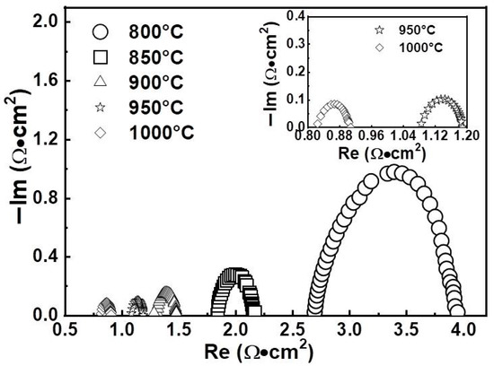
Figure 7.
Nyquist diagrams of the YSZ/LSM composite cathode deposited by SPPS.
Table 2 shows the polarization resistance values of the LSM [27] and YSZ/LSM cathodes at different temperatures. As indicated in Table 2, the cathodic polarization resistance decreased with increasing temperature. This is mainly due to the increase of cathodic activity and electrochemical reaction rate at the interface with the increase of temperature and thus decrease of the cathodic activation polarization [27]. From Table 2, the YSZ/LSM prepared by SPPS had a lower polarization resistance. When the temperature increased from 800 to 1000 °C, the polarization resistance decreased from 1.26 to 0.083 Ω·cm2. These values are about 0.31–0.55 times that of the LSM prepared by ethanol SPPS. This shows that the YSZ/LSM composite cathode had better performance than the single LSM cathode.
Table 2.
Comparison of polarization properties of YSZ/LSM and LSM.
4. Conclusions
In this paper, the microstructure of a YSZ/LSM composite cathode deposited by alcohol SPPS was studied. The effect of an annealing treatment on the morphology of the composite cathode was investigated, and the electrochemical performance of a YSZ/LSM composite cathode was also preliminarily studied. The results showed that the as-sprayed deposits presented a partially crystallized phase. After an annealing treatment at 1050 °C for 2 h, the deposits crystallized completely, and the morphology with a porous structure did not change greatly. The YSZ/LSM composite cathode was mainly composed of agglomerates containing spherical particles with a size of 0.2–2 μm. The polarization resistances of the YSZ/LSM composite cathode were 1.26 and 0.083 Ω·cm2 at 800 and 1000 °C, respectively, which were lower than the LSM cathode prepared under the same conditions. The addition of the YSZ electrolyte phase was beneficial to improving the cathode performance.
Author Contributions
Methodology, investigation, resources, writing—original draft preparation, and project administration, X.W.; Investigation, data curation, software, and writing—review and editing, B.T. and L.W.; Data curation and software, supervision, P.W. and W.D.; Funding acquisition, supervision, D.W. All authors have read and agreed to the published version of the manuscript.
Funding
This research was funded by Zhejiang Provincial Key Research and Development Project of China, Science and Technology Department of Zhejiang Province (Grant No. 2020C01153).
Institutional Review Board Statement
Not applicable.
Informed Consent Statement
Not applicable.
Data Availability Statement
The data supporting the finding of this study are available within the article.
Conflicts of Interest
The authors declare no conflict of interest.
References
- Xie, J.; Hao, W.; Wang, F. The analysis of interfacial thermal stresses of solid oxide fuel cell applied for submarine power. Int. J. Energy Res. 2018, 42, 2010–2020. [Google Scholar] [CrossRef]
- Boldrin, P.; Brandon, N.P. Progress and outlook for solid oxide fuel cells for transportation applications. Nat. Catal. 2019, 2, 571–577. [Google Scholar] [CrossRef] [Green Version]
- Waters, D.F.; Pratt, L.M.; Cadou, C.P. Gas Turbine/Solid Oxide Fuel Cell Hybrids for Aircraft Propulsion and Power. J. Propuls. Power 2021, 37, 349–361. [Google Scholar] [CrossRef]
- Mozdzierz, M.; Chalusiak, M.; Kimijima, S.; Szmyd, J.S.; Brus, G. An afterburner-powered methane/steam reformer for a solid oxide fuel cells application. Heat Mass Transf. 2018, 54, 2331–2341. [Google Scholar] [CrossRef] [Green Version]
- Singh, M.; Zappa, D.; Comini, E. Solid oxide fuel cell: Decade of progress, future perspectives and challenges. Int. J. Hydrogen Energy 2021, 46, 27643–27674. [Google Scholar] [CrossRef]
- Du, Y.; Finnerty, C.; Jiang, J. Thermal stability of portable microtubular SOFCs and stacks. J. Electrochem. Soc. 2008, 155, B972–B977. [Google Scholar] [CrossRef]
- Alenazey, F.; Alyousef, Y.; AlOtaibi, B.; Almutairi, G.; Minakshi, M.; Cheng, C.K.; Vo, D.V.N. Degradation behaviors of solid oxide fuel cell stacks in steady-state and cycling conditions. Energy Fuels 2020, 34, 14864–14873. [Google Scholar] [CrossRef]
- Lyu, Y.; Xie, J.; Wang, D.; Wang, J. Review of cell performance in solid oxide fuel cells. J. Mater. Sci. 2020, 55, 7184–7207. [Google Scholar] [CrossRef]
- Istomin, S.Y.; Lyskov, N.V.; Mazo, G.N.; Antipov, E.V. Electrode materials based on complex d-metal oxides for symmetrical solid oxide fuel cells. Russ. Chem. Rev. 2021, 90, 644–676. [Google Scholar] [CrossRef]
- Dwivedi, S. Solid oxide fuel cell: Materials for anode, cathode and electrolyte. Int. J. Hydrogen Energy 2020, 45, 23988–24013. [Google Scholar] [CrossRef]
- Sažinas, R.; Andersen, K.B.; Simonsen, S.B.; Holtappels, P.; Hansen, K.K. Silver modified cathodes for solid oxide fuel cells. J. Electrochem. Soc. 2019, 166, F79–F88. [Google Scholar] [CrossRef] [Green Version]
- Zhang, S.L.; Zhang, A.P.; Li, C.X.; Yang, G.J.; Li, C.J. Suspension Plasma Sprayed Sr2Fe1.4Mo0.6O6−δ Electrodes for Solid Oxide Fuel Cells. J. Therm. Spray Technol. 2017, 26, 432–440. [Google Scholar] [CrossRef]
- Meepho, M.; Wattanasiriwech, S.; Angkavatana, P.; Wattanasiriwech, D. Application of 8YSZ nanopowder synthesized by the modified solvothermal process for anode supported solid oxide fuel cells. J. Nanosci. Nanotechnol. 2015, 15, 2570–2574. [Google Scholar] [CrossRef] [PubMed]
- Zhang, S.L.; Huang, J.Y.; Li, C.X.; Yang, G.J.; Li, C.J. Relationship Between Designed Three-Dimensional YSZ Electrolyte Surface Area and Performance of Solution-Precursor Plasma-Sprayed La0.8Sr0.2MnO3−δ Cathodes. J. Therm. Spray Technol. 2016, 25, 1692–1699. [Google Scholar] [CrossRef]
- Jeon, O.S.; Park, M.G.; Song, R.H.; Ryu, K.H.; Na, C.W.; Shul, Y.G.; Lee, J.G. Effects of Fe2O3 doping on structural and electrical properties of 8 mol% yttria-stabilized zirconia electrolyte for solid oxide fuel cells. J. Mater. Sci. Mater. Electron. 2022, 33, 3208–3214. [Google Scholar] [CrossRef]
- Khan, M.; Zeng, Y.; Hu, N.; Lan, Z.; Wang, Y. Optimizing the structure and properties of Y2O3 stabilized zirconia: An atmospheric plasma spray (APS) and solution precursor plasma spray (SPPS) based comparative study. Ceram. Int. 2018, 44, 18135–18142. [Google Scholar] [CrossRef]
- Tahir, N.N.M.; Baharuddin, N.A.; Samat, A.A.; Osman, N.; Somalu, M.R. A review on cathode materials for conventional and proton-conducting solid oxide fuel cells. J. Alloys Compd. 2022, 894, 162458. [Google Scholar] [CrossRef]
- Shi, H.; Su, C.; Ran, R.; Cao, J.; Shao, Z. Electrolyte materials for intermediate-temperature solid oxide fuel cells. Prog. Nat. Sci. Mater. 2020, 30, 764–774. [Google Scholar] [CrossRef]
- Hussain, S.; Li, Y.P. Review of solid oxide fuel cell materials: Cathode, anode, and electrolyte. Energy Trans. 2020, 4, 113–126. [Google Scholar] [CrossRef]
- Rafique, M.; Nawaz, H.; Shahid Rafique, M.; Bilal Tahir, M.; Nabi, G.; Khalid, N.R. Material and method selection for efficient solid oxide fuel cell anode: Recent advancements and reviews. Int. J. Energy Res. 2019, 43, 2423–2446. [Google Scholar] [CrossRef]
- Zhang, S.L.; Li, C.J.; Li, C.X.; Yang, G.J.; Huang, K.; Liu, M. Liquid plasma sprayed nano-network La0.4Sr0.6Co0.2Fe0.8O3/Ce0.8Gd0.2O2 composite as a high-performance cathode for intermediate-temperature solid oxide fuel cells. J. Power Sources 2016, 327, 622–628. [Google Scholar] [CrossRef]
- Timurkutluk, B.; Timurkutluk, C.; Mat, M.D.; Kaplan, Y. A review on cell/stack designs for high performance solid oxide fuel cells. Renew. Sustain. Energy Rev. 2016, 56, 1101–1121. [Google Scholar] [CrossRef]
- Agbede, O.O.; Hellgardt, K.; Kelsall, G.H. Electrical conductivities and microstructures of LSM, LSM-YSZ and LSM-YSZ/LSM cathodes fabricated on YSZ electrolyte hollow fibres by dip-coating. Mater. Today Chem. 2020, 16, 100252. [Google Scholar] [CrossRef]
- Joulia, A.; Bolelli, G.; Gualtieri, E.; Lusvarghi, L.; Valeri, S.; Vardelle, M.; Rossignol, S.; Vardelle, A. Comparing the deposition mechanisms in suspension plasma spray (SPS) and solution precursor plasma spray (SPPS) deposition of yttria-stabilised zirconia (YSZ). J. Eur. Ceram. Soc. 2014, 34, 3925–3940. [Google Scholar] [CrossRef] [Green Version]
- Pawlowski, L. Finely grained nanometric and submicrometric coatings by thermal spraying: A review. Surf. Coat. Technol. 2008, 202, 4318–4328. [Google Scholar] [CrossRef]
- Wang, X.M.; Li, C.X.; Li, C.J.; Tian, L.H.; Yang, G.J. Microstructure and electrochemical behavior of La0.8Sr0.2MnO3 deposited by solution precursor plasma spraying. Rare Met. Mater. Eng. 2011, 40, 1881–1886. [Google Scholar]
- Wang, X.M.; Li, C.X.; Li, C.J.; Yang, G.J. Microstructure and polarization of La0.8Sr0.2MnO3 cathode deposited by alcohol solution precursor plasma spraying. Int. J. Hydrogen Energy 2012, 37, 12879–12885. [Google Scholar] [CrossRef]
- Prakash, B.S.; Kumar, S.S.; Aruna, S.T. Microstructure and performance of LSM/YSZ based solid oxide fuel cell cathodes fabricated from solution combustion co-synthesized powders and by solution precursor plasma spraying. Surf. Coat. Technol. 2017, 310, 25–32. [Google Scholar] [CrossRef]
- Wang, X.M.; Li, C.X.; Li, C.J.; Yang, G.J. Effect of microstructures on electrochemical behavior of La0.8Sr0.2MnO3 deposited by suspension plasma spraying. Int. J. Hydrogen Energy 2010, 35, 3152–3158. [Google Scholar] [CrossRef]
- Chen, D.; Jordan, E.; Gell, M. Thermal and crystallization behavior of zirconia precursor used in the solution precursor plasma spray process. J. Mater. Sci. 2007, 42, 5576–5580. [Google Scholar] [CrossRef]
- Deng, X.; Petric, A. Geometrical modeling of the triple-phase-boundary in solid oxide fuel cells. J. Power Sources 2005, 140, 297–303. [Google Scholar] [CrossRef]


Publisher’s Note: MDPI stays neutral with regard to jurisdictional claims in published maps and institutional affiliations. |
© 2022 by the authors. Licensee MDPI, Basel, Switzerland. This article is an open access article distributed under the terms and conditions of the Creative Commons Attribution (CC BY) license (https://creativecommons.org/licenses/by/4.0/).