Article

Study on the Impact Resistance of FRP Pasted onto a Blastproof Partition Wall under Out-of-Plane Repeated Impact Load

1
School of Civil Engineering, Qingdao University of Technology, Qingdao 266520, China
2
Co-operative Innovation Center of Engineering Construction and Safety in Shandong Blue Economic Zone, Qingdao 266033, China
3
Qingdao First Municipal Engineering Co., Ltd., Qingdao 266034, China
4
Qingdao GuoGong High-TECH Materials Co., Ltd., Qingdao 266035, China
*
Author to whom correspondence should be addressed.
Coatings 2022, 12(12), 1836; https://doi.org/10.3390/coatings12121836
Submission received: 3 November 2022 / Revised: 15 November 2022 / Accepted: 22 November 2022 / Published: 27 November 2022

Abstract

:
A blastproof partition wall in civil air defense engineering is easily subjected to out-of-plane impact loads, such as object impacts, and structural collapse in peacetime. In this study, the pendulum impact test was carried out for the first time on six blastproof partition walls pasted with fiber-reinforced polymer (FRP). Using a method combining finite element simulation and experimental research, the influence of parameters such as the FRP type, layer number and width, and pendulum impact number on the impact resistance of the wall was systematically studied. The test results show that pasting FRP on the back of the blastproof partition wall can significantly improve the impact resistance and reduce the damage degree of the concrete. The impact recovery coefficient increased from 0.33 to 0.57, but with the increase in the number of impacts, large-rupture-strain FRP (LRS-FRP) can give full play to the advantages of a large tensile fracture strain and cooperate with the wall to deform, and the selection of FRP with a large tensile fracture strain is the key to resisting multiple impact loads. Finally, the experimental basis and an economical and reliable protection method are provided for the study of improving the impact resistance of the blastproof partition wall.

1. Introduction

With the frequent occurrence of accidents such as falling rocks, vehicle impacts, and natural gas pipeline explosions, the impact load is rarely considered in the design of existing concrete structures, resulting in the insufficient impact resistance and collapse resistance of some important building structures [1,2,3,4]. Previous studies have shown that FRP can significantly improve the impact resistance of concrete structures. Under the action of dynamic loads, the reinforcement technology of reinforced concrete structures using FRP is mainly concentrated in the experimental research stage. Scholars have conducted extensive research on reinforced concrete (RC) beams and columns and carried out a large number of drop hammer impact tests [5,6].
At present, the research on the dynamic impact resistance of FRP-reinforced engineering components is very limited. Shen et al. [7] added fiber to concrete and studied the impact resistance of fiber-reinforced concrete, and hybrid fibers had high impact resistance. Zhou et al. [8] studied the impact properties of PET-reinforced concrete under a high strain rate and obtained a linear relationship between the ultimate compressive strain of concrete and time at relatively low energy. Almusallam et al. [9] carried out drop hammer impact tests on different types of RC beams. Hybrid fibers can improve the impact resistance of beams, and the proposed modified model can predict the deformation mode of beams. Swesi et al. [10] conducted a lateral impact load test on twenty carbon-fiber-reinforced polymer (CFRP)-coated reinforced concrete columns. CFRP reinforcement can improve resistance but largely depends on the internal structure of the CFRP fiber material. Pham et al. [11] used FRP for the flexural reinforcement of beams, and the U-shaped FRP reinforcement method provided better impact resistance and bending resistance than the vertical FRP reinforcement method. Under the action of an impact load, CFRP-bonded concrete structures are more sensitive to local defects, and the damage caused by CFRP failure may be more serious [12,13].
Cho et al. [14] completed the drop hammer impact test on seven reinforced concrete beams reinforced with carbon fibers and steel fibers, and the results showed that the flexural bearing capacity of the reinforced test beams was significantly improved. Kantar et al. [15] completed the drop hammer impact test on ten CFRP-reinforced beams, and the results show that the CFRP reinforcement method can prevent the beam from fracture and damage and has a better energy absorption performance. Pham and Shan et al. [16,17,18] studied the dynamic properties of different FRP types of constrained concrete. Compared with CFRP, glass-fiber-reinforced polymer (GFRP) and basalt-fiber-reinforced polymer (BFRP) have better impact resistance. In terms of numerical simulation, for the finite element simulation of RC beams reinforced by fiber composite materials, the main focus is on the bond-slip performance simulation of the interface between FRP and concrete and the improvement in FRP reinforcement on the static and dynamic performance of the structure. Zhang et al. [19] proposed an interface constitutive model suitable for fatigue performance analysis of CFRP-reinforced concrete beams. Huang et al. [20] conducted a refined numerical simulation of the static and dynamic performance of concrete beams reinforced with basalt fibers. Jin et al. [21] established a shear wall impact resistance model. The impact velocity has a great influence on the local damage degree, and increasing the edge members can reduce the damage degree. Daneshvar et al. [22] studied the drop hammer impact on RC slabs. For a low-velocity impact, the impact resistance has a strong relationship with the amount of reinforcement. Jin et al. [23] conducted experimental research on GFRP-bar-reinforced RC slabs subjected to different impact masses and speeds and observed that GFRP bars have a better energy dissipation capacity during impacts. Under an impact load, the failure process of concrete is relatively complex, but researchers can predict the failure probability of concrete by using new technologies to ensure the safety of the structure [24,25].
The above research shows that research on the impact resistance of reinforced concrete members is mainly focused on RC beams, and all of them are damaged by the first impact of the drop hammer. There has been no experimental research on the impact resistance of FRP-pasted blastproof partition walls. In order to make up for this research gap, in this study, the out-of-plane pendulum impact test was carried out on six blastproof partition walls pasted with different types of FRP. The effects of the FRP type, layer number, pendulum impact height and the number of impacts on resistance were studied. Finally, this study provides an experimental basis for the application of FRP in civil air defense engineering.

2. Experimental Tests

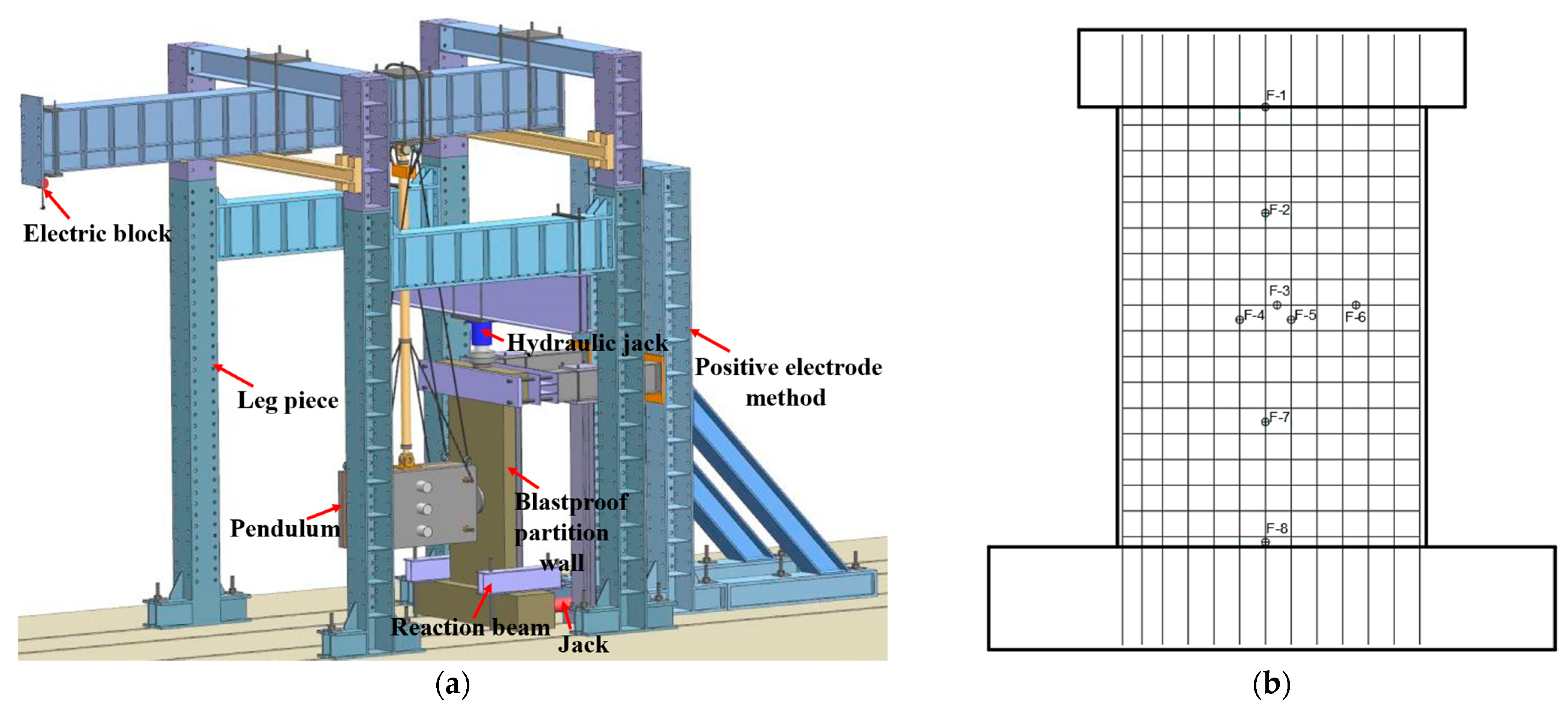
This section describes the size and reinforcement of the six designed blastproof partition walls, as shown in Figure 1, the mechanical properties of the tested materials, as shown in Figure 2 and the details of the structure and parameters of the pendulum impact device, as shown in Figure 3.

2.1. Specimen Design

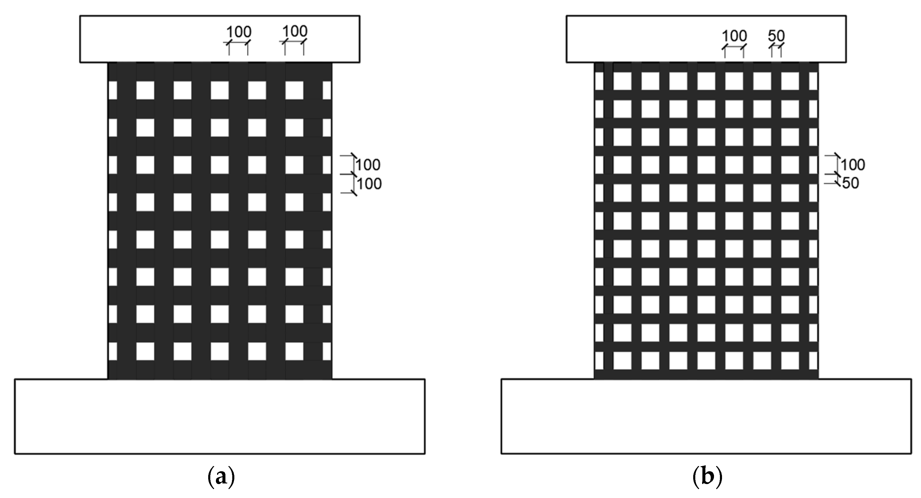
In the experiment, six blastproof partition walls with the same reinforcement were designed. Among them, one was unpasted FRP, two were pasted with CFRP, one was pasted with AFRP, and two were pasted with large-rupture-strain FRP. The blastproof partition wall was 1700 mm high, 1200 mm wide, and 150 mm thick, with an aspect ratio of 1.4 and a concrete cover of 20 mm. The steel bars of the wall were of HRB400 grade, the longitudinal and transverse steel bars were 8 mm in diameter, and the spacing was 100 mm. The diameter of the stirrups was 6 mm, and the spacing was 200 mm. The detailed dimensions and reinforcement of the specimen are shown in Figure 1. In this experiment, the impact mass of the pendulum was 2000 kg, the impact number was 2, and the 2 impact heights were 0.4 m and 0.8 m. The numbers of blastproof partition wall specimens are shown in Figure 4 and Table 1. Taking BC2-100-1 as an example, B denotes an empty wall, C denotes CFRP on the back, the number 2/1 denotes the number of layers, and 100 denotes the width of the CFRP.

2.2. Material Properties

In the test, the strength grade of the wall concrete was C35, and the mix ratio of the concrete was cement/water/sand/stone/fly-ash/admixture = 1:0.5:2.2:2.8:0.2:0.03. The maximum particle size of the crushed stone in the aggregate was 25 mm. A 100 mm × 100 mm × 100 mm concrete cube test block was reserved for each pouring of concrete, and the average compressive strength was measured to be 38.1 MPa. The CFRP sheet and aramid-fiber-reinforced polymer (AFRP) sheet selected in the test are both unidirectional sheets. Large-rupture-strain FRP (LRS-FRP) is a new type of fiber material. The tensile fracture strain value is greater than 5%, which is more than two times that of common FRP, which can make up for the shortcomings of common FRP. There are two types of PEN and PET. The large-rupture-strain FRP model selected in this study is PET-600, as shown in Figure 2a. According to “Test Methods for Tensile Properties of Fiber Reinforced Plastics”, five FRP specimens with a width of 25 mm and a length of 260 mm were fabricated, and aluminum sheets were attached to the ends of the specimens for loading and clamping. The tensile test of the FRP sheet sample was carried out using an electronic universal testing machine, and the tensile specimen is shown in Figure 2b. The material properties of the three different FRPs were obtained, as shown in Table 2. In this study, the type of epoxy resin glue for adhering FRP was L-500, which was mixed with A and B adhesives, and the mixing ratio was 2:1. It can be applied to the bonding of FRP in various outdoor environments, such as different seasons and different temperature ranges, and the material properties are shown in Table 3.

2.3. Pendulum Impact Device

The impact test adopted a pendulum impact device independently developed by our research group, which uses a single impact load in the center of the wall, and an impact force sensor is installed at the front end of the pendulum. The sensor range is 3500 kN, and the maximum weight of the pendulum is 5000 kg. The mass selected in this experiment is 2000 kg. In order to prevent single-point damage, a 340 mm × 340 mm × 50 mm steel plate was pasted at the center of the impact surface of the blastproof partition wall, and high-speed cameras were placed on the side and back of the wall to record the dynamic response and mid-span displacement of the wall during the entire impact process. The impact force, displacement, and strain data were collected by a DH5922D collector, and the sampling frequency was 20 kHz. The detailed test device and strain measuring point position and direction are shown in Figure 3.

3. Analysis of Pendulum Impact Test Results

In this section, the dynamic response of the pendulum impact of the blastproof partition wall is explained in detail, and the contribution of FRP to the impact resistance is finally obtained.

3.1. Destruction Form

The blastproof partition wall without FRP showed an obvious bending failure under the out-of-plane pendulum impact load, and the local concrete seriously failed, as shown in Figure 5. Under the action of the local impact load, cracks on the back of the wall are centered on the impact area and spread to the surrounding areas. The number of transverse cracks is greater than that of vertical cracks. Due to the low flexural stiffness of the wall, the concrete on the impact surface fell off, the steel bars were exposed, and there were splashes of larger concrete fragments on the back. When the FRP sheet is pasted on the back of the blastproof partition wall, as shown in Figure 6a, and the wall is subjected to an impact load, it is pulled along the direction of FRP sheet pasting, which increases the bending stiffness of the back and reduces the deformation of the wall when the impact load is too large. Finally, the wall was damaged by the fracture of the FRP sheet. Taking the AFRP sheet pasted on the back as an example, as shown in Figure 6b,c, under the impact of the first pendulum, the wall maintains a good degree of integrity, but small cracks are formed on the back. The synergistic deformation of the AFRP sheet and the wall can effectively improve the impact resistance, reduce residual deformation, and prevent peeling. After the second pendulum impact, the AFRP sheet peeled off from the concrete, and the concrete was severely damaged. Therefore, fragments fell off the concrete surface, but the damage was less than that of the blastproof partition wall without FRP.

3.2. Impact Response Curve

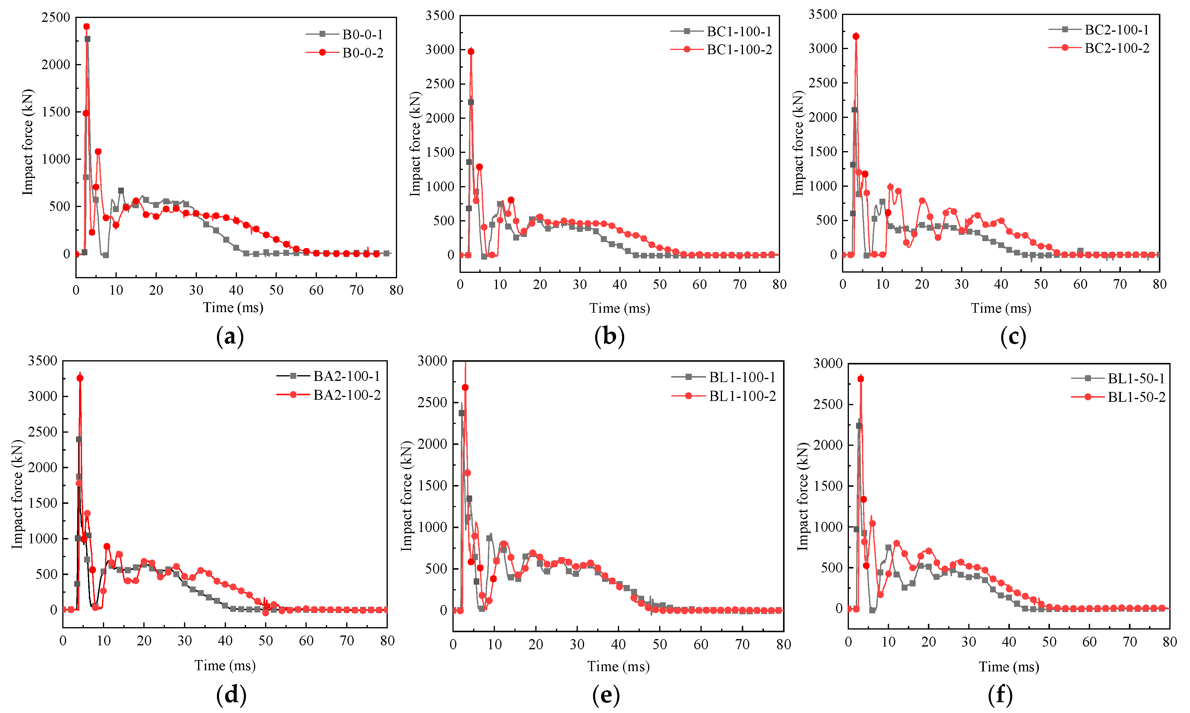
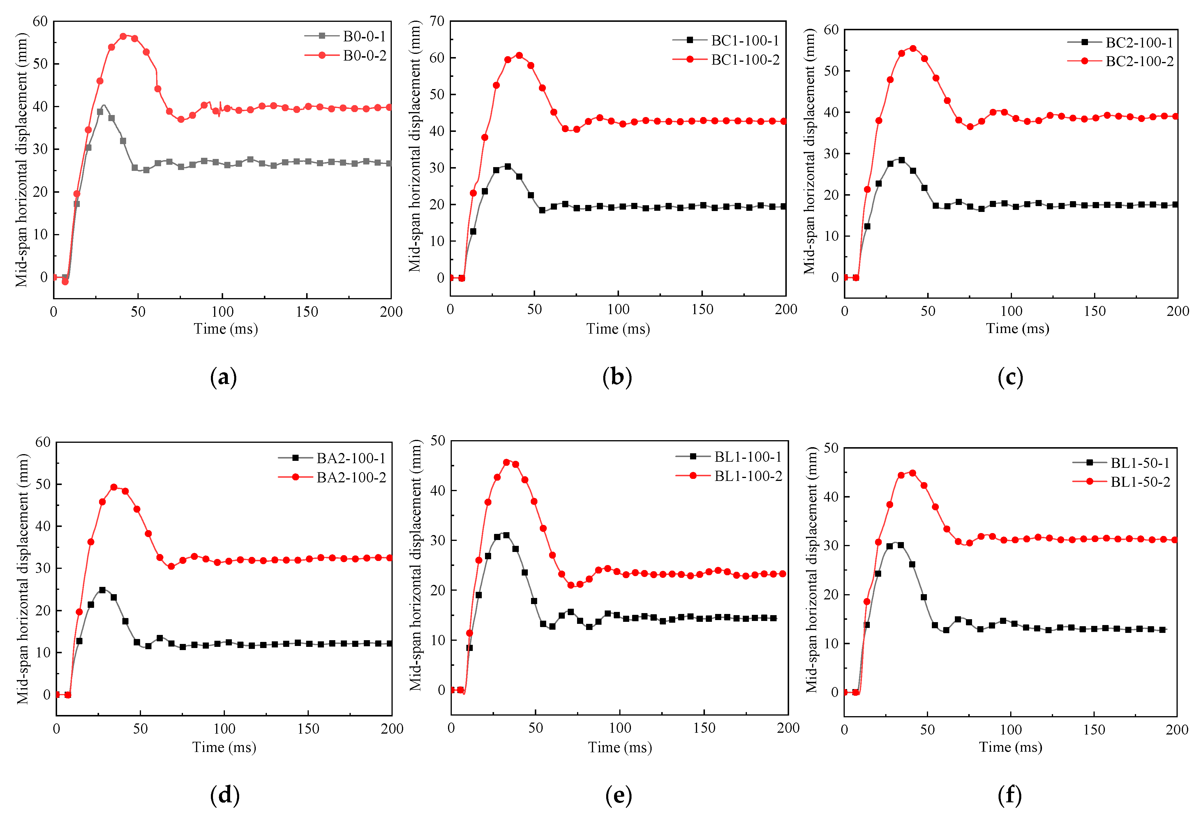
The impact force/mid-span horizontal displacement time-history curve is an important index for measuring the impact resistance of the wall. The response curves of each specimen under multiple impact loads are shown in Figure 7 and Figure 8. The entire impact force time-history curve shows a part of the temporary wave with a large peak and a short duration and the other part of the main wave with a small peak and a long duration, which is consistent with the shock waveform mentioned in [26]. The first and second pendulum impact energies are 7.84 and 15.68 kJ, respectively. It can be seen in Figure 6 and Table 4 that under the first pendulum impact, the peak impact force of specimen B0-0 is 2289.2 kN, and the maximum impact force of the specimen pasted with the FRP sheet is 2498.1 kN. There is little difference in the peak impact force of different specimens. When the second pendulum impact was performed, the peak impact force of the unprotected wall increased by 5.6%, the peak impact force of the wall pasted with the FRP sheet increased significantly, and the peak impact force of specimen BC2-100 increased by 43.8%, indicating that the CFRP sheet has high tensile strength and can provide greater bending stiffness. As the number of impacts increases, the damage to the wall continues to accumulate, and the degree of concrete cracking also increases, resulting in a decrease in the frequency of the wall itself. This also shows that at the same impact height, the peak impact force is related to the stiffness of the wall. FRP will not affect the peak value of the first impact force, but with the increase in the number of impacts, pasting the FRP sheet on the back of the wall can provide greater flexural stiffness, ensure the integrity of the concrete, and improve the impact resistance of the wall. From the displacement time-history curve shown in Figure 7, it can also be concluded that FRP can significantly reduce the residual displacement of the wall. After two pendulum impacts, the residual displacement is reduced by a maximum of 59%, ensuring that the wall is within the elastic range and has sustainable resistance to impact loads.
In addition to the impact force and displacement, the recovery ability of the blastproof partition wall after the impact is also an important parameter to measure the impact resistance. The larger the impact recovery coefficient, the stronger the impact recovery ability. It can be seen in Table 4 that under the first pendulum impact, pasting FRP on the back of the blastproof partition wall can increase the impact recovery coefficient from 0.33 to 0.57, effectively improving the deformation recovery ability of the blastproof partition wall, mainly because of the high strength of FRP, which is basically in the elastic stage before the tensile fracture. In particular, the large-rupture-strain FRP has the largest tensile fracture strain, and it retracts after the impact and, at the same time, drives the adjacent wall to recover and deform.

3.3. Crack Morphology

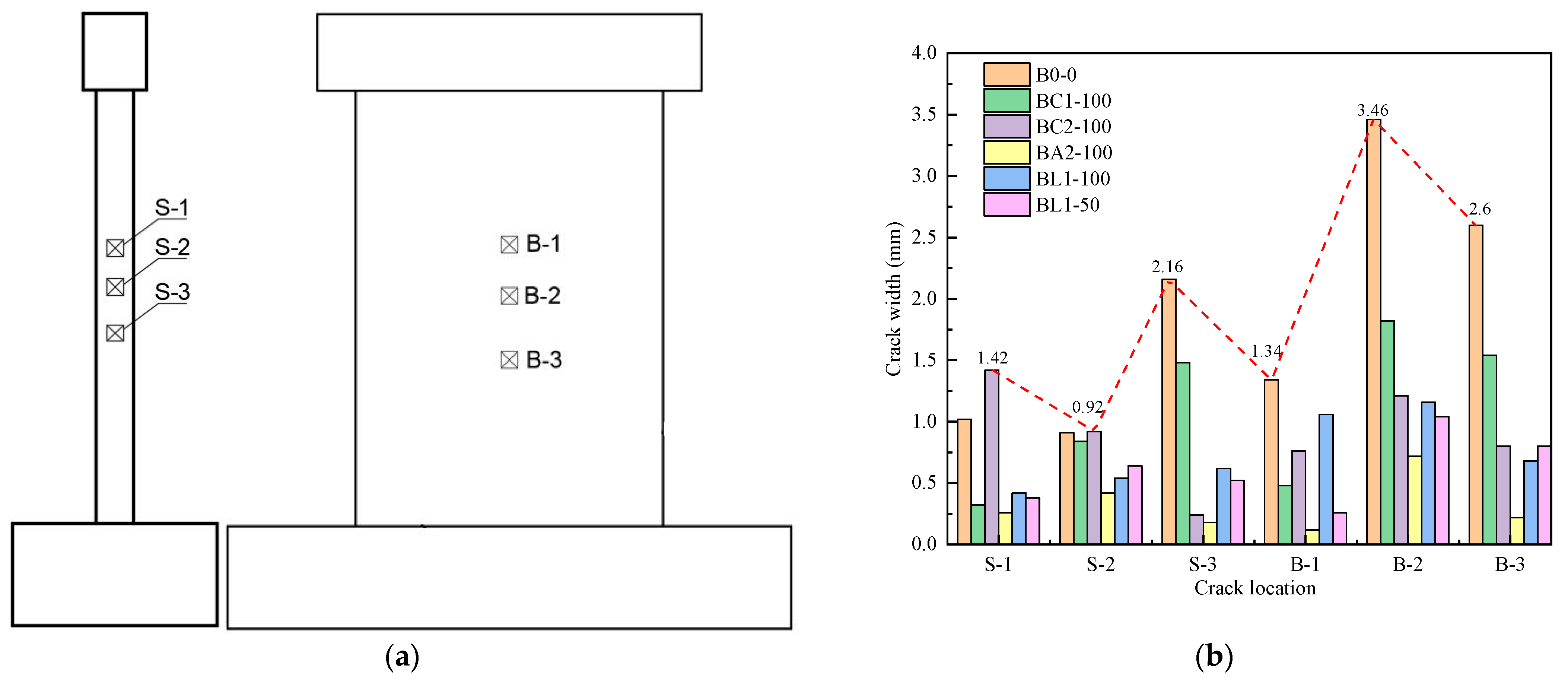
Under the action of the impact load, the widths of concrete cracks in important positions on the side and back of the blastproof partition wall were measured, and the positions of the crack measurement points are shown in Figure 9a. The width and morphology of concrete cracks when the impact energy of the pendulum is 7.84 kJ are shown in Figure 9b and Table 5. The maximum crack widths on the side and back of specimen B0-0 are 2.16 mm and 3.46 mm, respectively. After pasting FRP on the back of the wall, the maximum crack width on the side of specimen BA2-100 is 0.42 mm, the minimum crack width is reduced by 80.6%, and the back crack width is reduced by 79.2%. This is mainly due to the fact that FRP can improve the bending stiffness of the wall back, reduce the peak mid-span horizontal displacement of the wall and the deformation of the steel bar, and prevent the large-scale cracking of concrete that results in transverse cracks.

3.4. Strain Time-History Curve

In this study, the important longitudinal stress steel strain measuring points at the top (Measuring Point 1), the middle (Measuring Point 4) and the bottom (Measuring Point 8) of the blastproof partition wall were selected for analysis. The steel bar strain time-history curves of different specimens are shown in Figure 10. Under the action of an impact load, the strain of the steel bar in the wall will quickly reach the peak strain, and then the residual strain will be generated by retraction; the peak strains of longitudinally stressed steel bars all exceed 1000 με. It can be seen in Figure 10a,b that the peak value of the steel bar strain at the bottom of the same wall is greater than that at the top, which can directly reflect the vibration of the wall during the impact of the pendulum, and the vibration amplitude of the top steel bars is small, indicating that the rotational restraint capacity of the bottom of the wall is greater than that of the top.
In Figure 10c, it can be seen that the peak value of the steel bar strain in the impact center area of the unprotected wall reaches 8800 με. Specimen BC1-100 also has a peak value of steel bar strain of more than 6000 με due to the fracture of the CFRP sheet during the impact process. This shows that all of the steel bars in the wall yield here and eventually fluctuate within a stable range. With the increase in the number of CFRP layers, the peak strain of the steel bar decreases significantly. When large-rupture-strain FRP is pasted on the back, the peak strain and residual strain of the steel bar are small, which can ensure that the steel bar is within the elastic range, reduce the residual deformation of the wall, and improve the ability to resist impact loads.

3.5. FRP Impact Resistance Contribution

The purpose of pasting the FRP sheet on the back of the blastproof partition wall is to improve the impact resistance of the wall, preventing local concrete damage that leads to an overall collapse. Whether under a static load or an impact load, the FRP sheet can improve the bending stiffness of the wall. In order to analyze the contribution of the FRP sheet to improving the impact resistance and bending resistance of the blastproof partition wall under the out-of-plane pendulum impact load, based on the American specification ACI 440.2R-08 [27], an analysis of the contribution of FRP types and layers to its resistance is necessary.
When the blastproof partition wall faces an impact load, the local concrete of specimen B0-0 fails, a bending failure occurs, and the bending resistance is obviously insufficient. When the FRP sheet was pasted on the back of the wall, the bending stiffness increased by 38% at its maximum, and the residual deformation was reduced by 41.7% at its maximum. The tensile strength and tensile fracture strain of the three FRPs are different. Under the same impact load conditions, the large-rupture-strain FRP did not fracture, and the residual deformation of the wall was significantly reduced. Despite the high tensile strength of the CFRP sheet, a fracture occurred at the first pendulum impact. The AFRP sheet fractured under the second pendulum impact and finally lost its protective ability. Even if the number of pasting layers of the CFRP sheet is increased, although the flexural stiffness is increased, it does not have the advantage of high tensile strength compared with large-rupture-strain FRP pasted in one layer.
When the FRP sheet is pasted on the back of the blastproof partition wall, it shows sufficient impact resistance before the FRP sheet fractures. According to the research results of the impact resistance test in this paper, the selection of FRP with a large tensile fracture strain is the key to improving the impact resistance of the blastproof partition wall, which can prevent the premature failure of the wall due to FRP fracture and improve the ability of the wall to resist multiple impact loads.

4. Parametric Analysis

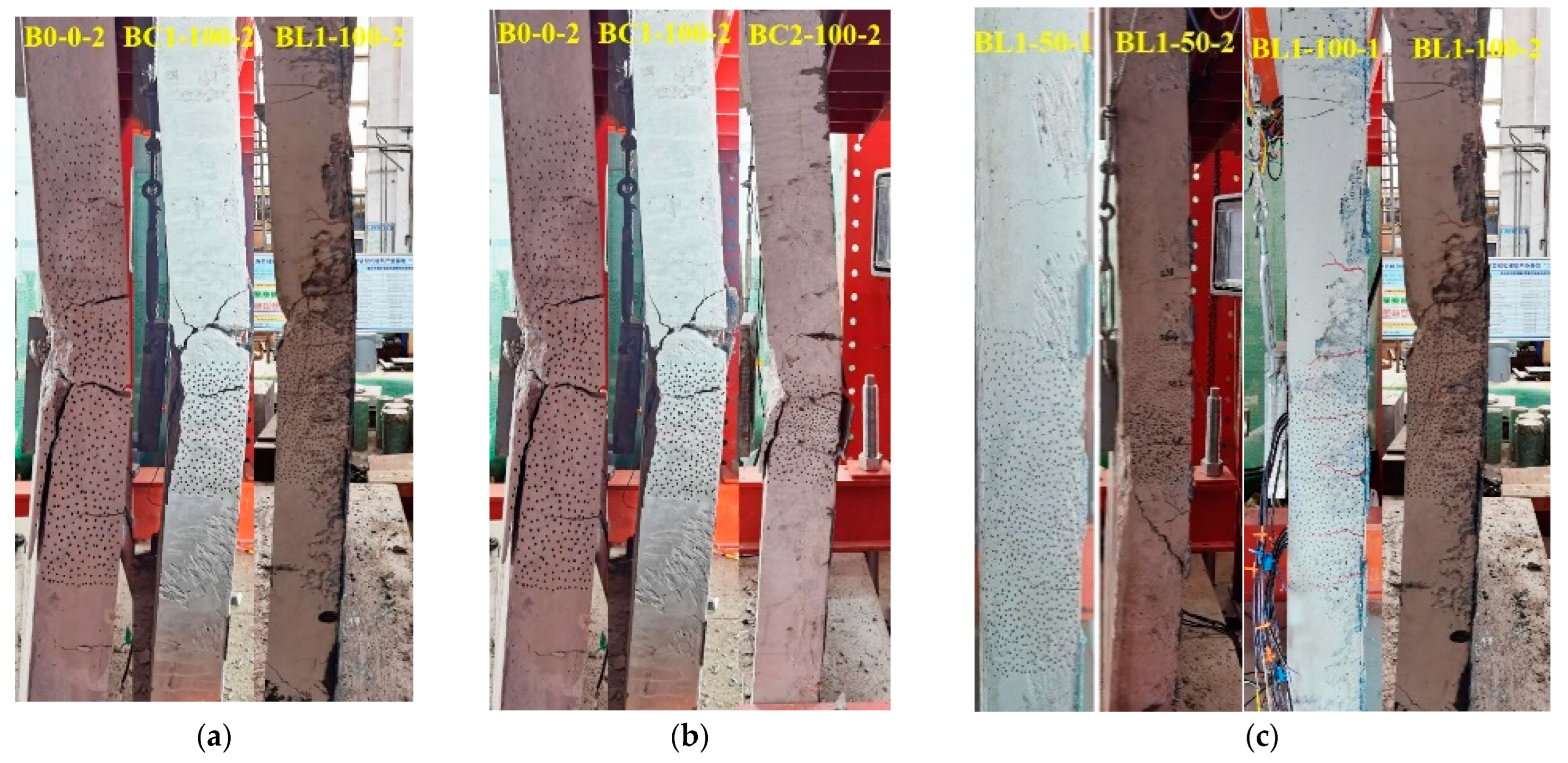
In this paper, the ability of the blastproof partition wall to resist out-of-plane pendulum impact loads is directly related to FRP. In order to compare the influence of different FRPs on the impact resistance of the blastproof partition wall, in this section, the influence of parameters such as the FRP type, layer number, and width on the impact resistance of the blastproof partition wall is analyzed (Figure 11).

4.1. FRP Type

In this test, a total of three kinds of FRP walls, CFRP, AFRP, and LRS-FRP, were tested for impact resistance. Due to space limitations, the wall with one layer of FRP was analyzed, as shown in Figure 11a. The crack width and damage on the side of specimen BL1-100 are significantly smaller than those of specimen BC1-100; the maximum crack width on the back is reduced from 1.82 to 1.16 mm, and the maximum crack width on the side is reduced by 58.1%. Since the main difference between the three FRPs is the difference in tensile strength and tensile fracture strain, the damage degree of the wall decreases with the increase in the fracture strain of FRP, so the ability of the wall to resist multiple impact loads is significantly improved. Under the first pendulum impact load, the peaks of the mid-span horizontal displacements of the two FRP walls are almost the same, because the elastic modulus of CFRP is higher than that of the other two FRPs. Before the impact fracture occurs, the enhancement effect on the stiffness of the specimen is more obvious.

4.2. Number of FRP Layers

In order to study the effect of the number of FRP layers on the impact resistance of the blastproof partition wall, specimens with one and two CFRP layers were analyzed, and the other working conditions were the same. The mid-span horizontal displacement peak value and the residual displacement of specimen BC2-100 are smaller than those of specimen BC1-100, as shown in Figure 11b. After two pendulum impacts, the mid-span displacement and damage degree of the one-layer CFRP wall are significantly higher. The maximum displacement reaches 60.8 mm, while the maximum displacement of the two-layer CFRP wall is 55.5 mm, which is 8.7% less than that of the one-layer CFRP wall. The damage degree and area of the one-layer CFRP wall concrete are larger, resulting in impact crushing. This is because CFRP has already fractured during the first pendulum impact, and the damage degree further increases with the increase in the impact number and impact energy. The two-layer CFRP can maintain the stiffness and ductility of the wall, reduce the extension of cracks along the wall thickness direction, and prevent greater damage to the wall. Therefore, under the same working conditions, the impact resistance of two layers of CFRP pasted on the back of the blastproof partition wall is better under multiple impact loads.

4.3. FRP Width

In this study, large-rupture-strain FRP with a larger tensile fracture strain was selected for the pendulum impact test, and the width of the large-rupture-strain FRP was reduced from 100 to 50 mm to ensure that the pasting distance and impact conditions remained unchanged. The protective area of the blastproof partition wall is reduced by 19.6%, as shown in Figure 11c. In the case of the decreased FRP width, the two impact forces and the peak mid-span displacement hardly changed, but the final residual displacement of the wall decreased from 31.2 mm for specimen BL1-50 to 23.2 mm for specimen BL2-100, which is a decrease of 25.6%. As the width increased, the maximum crack width on the side and back of the concrete decreased, and specimen BL1-50 eventually failed due to the large diagonal crack on the side. However, the large-rupture-strain FRP did not fracture, so the internal cracks in the concrete fully developed along the width of the wall under the impact load. The FRP width of specimen BL1-100 is larger, so it has better toughness and deformation ability and can maintain better wall integrity under an impact load, which is more conducive to improving the impact resistance of the blastproof partition wall.

5. Comparison between Finite Element Simulation Results and Experiments

In this section, the finite element model of the pendulum impact is established, and the correctness of the finite element simulation is verified. The material model in this paper can be applied to pendulum impacts.

5.1. Finite Element Model

In this work, the display dynamic analysis software LS-DYNA (version V971) was used to establish the finite element model of the pendulum impact, as shown in Figure 12. The finite element model adopts the method of full-scale modeling. The whole model mainly includes the pendulum, blastproof partition wall, FRP, and fixed components. The concrete, pendulum, and fixed components in the model use solid164 elements, and FRP uses shell163 elements; the element size is 10 mm. The number of elements in the whole model is 1,280,000; the bottom of the blastproof partition wall is a fixed constraint, and the top limits horizontal movement and rotation. The contact between the components in the finite element model is face-to-face contact. The bond between the steel bar and the concrete is defined by *CONSTRAINED_LAGRANGE_IN_SOLID. The impact load is applied by defining the initial velocity of the pendulum. The finite element calculation time is 200 ms.
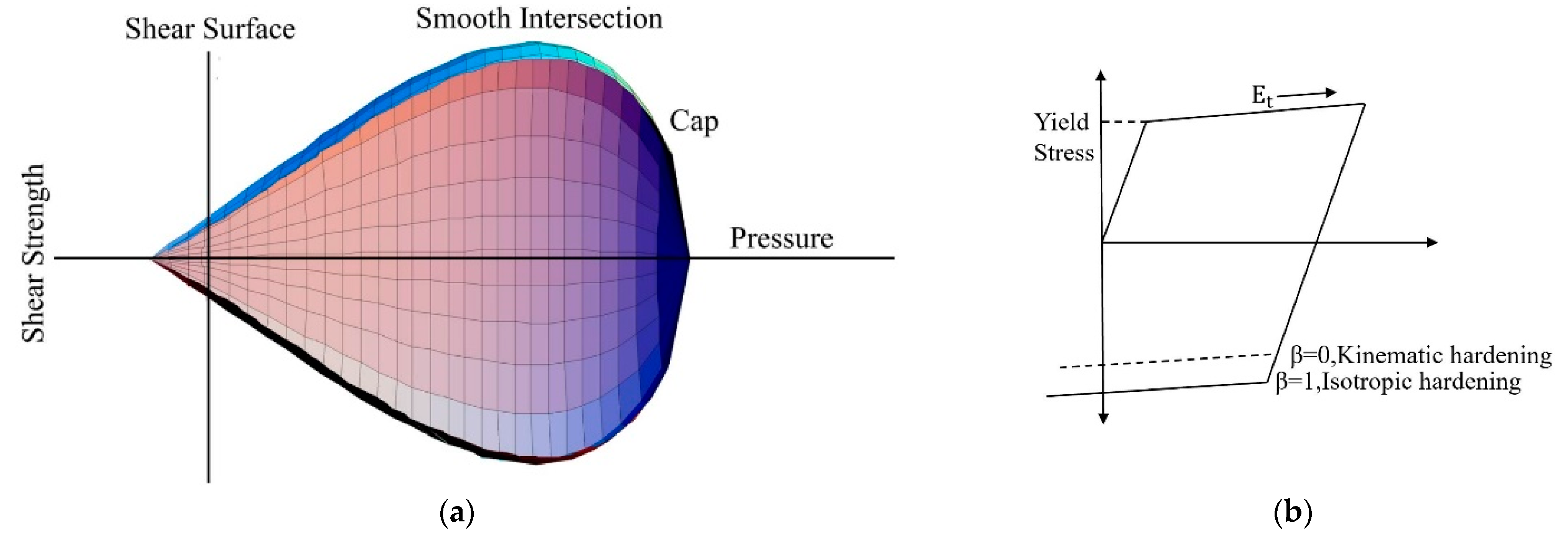
In LS-DYNA, there are many constitutive models used to define concrete, while the damage models used for concrete under an impact load mainly include MAT-72R3 and MAT-159 [28]. Considering that the pendulum impact in this paper is a low-velocity impact, the CSCM model is a dynamic damage model, as shown in Figure 13a, which was first used to simulate the impact of vehicles on a roadside protective fence. It can accurately simulate the dynamic response of concrete structures under impact loads [29], and it was later used by the US Federal Highway Administration to conduct related vehicle impact studies [30]. So, the CSCM model (MAT-159) was selected to simulate the impact of a pendulum on a blastproof partition wall. This model has a wide range of applications in fields requiring the simulation of reinforced concrete subjected to low-velocity impact loads, and it can better simulate the bending and shear failure of reinforced concrete structures under impact loads. The model takes into account the hardening, damage, and strain rate dependencies of the material, and the maximum particle size of the concrete aggregate in the specimen is 25 mm.
The steel bar in the specimen adopts the bilinear kinematic hardening model (MAT_PLASTIC_KINEMATIC), as shown in Figure 13b, which includes the strain rate formula to calculate the strain rate effect, and uses the Cowper–Symonds model to consider the strain rate effect of the steel bar. The yield strength of steel bars at different strain rates is:
σ y = [ 1 + ( ε · C ) 1 P ] ( σ 0 + β E p ε p e f f )
where σ 0 is the initial yield stress, ε · is the strain rate, ε p e f f is the effective plastic strain, β is the hardening parameter, and C and P are the strain rate parameters, which are generally obtained from material test fitting, and existing researchers have found that for the case of a low-speed impact, C = 6844 s − 1 and P = 3.91 can better show the characteristics of the steel strength as it changes with the strain rate effect [31,32,33]. Therefore, this study used the values in the literature to consider the steel strain rate effect. It is necessary to input parameters such as the steel density, elastic modulus, yield strength, and failure strain into the model. In this paper, the failure strain of steel bars is taken as 0.12.
The FRP sheet is an orthotropic material with linear elastic deformation behavior and relatively small ultimate fracture strain before yielding, so the MAT_ENHANCED_COMPOSITE_DAMAGE (MAT_54) material model in LS-DYNA was adopted, which considers the linear elastic behavior and brittle failure of composite materials, and the failure of the composite layer was judged by the Chang–Chang failure criterion. In the material model, only the longitudinal tensile strength needs to be input to realize the FRP fracture failure criterion. The impact failure simulation is realized by setting parameters such as tensile strength, fracture strain, elastic modulus, etc. The bonding relationship between FRP and concrete adopts an interface failure, and the contact relationship between FRP and concrete is simulated by defining the automatic surface–surface contact keyword. Only the tensile failure of the interface is considered, and the failure criterion is:
σ n 2 + 3 σ s 2 N lfs 1
where σ n and σ s are the normal and shear stresses of the bonding interface during deformation, respectively, and N lfs is the ultimate bond strength of the colloid under ideal conditions. In this paper, the impact velocity of the pendulum has little effect on the tensile strength and elastic modulus of FRP [34,35], and the effect of the strain rate on the material can be ignored. Since the fixture in the test did not deform during the entire impact process, the rigid body material model (MAT_RIGID) was selected for the simulation, the commonly used linear elastic material model (MAT_ELASTIC) was selected for the pendulum, and the mass of the pendulum was determined by inputting the density. The detailed material model parameters are shown in Table 6.

5.2. Damage Comparison

From the finite element simulation of six blastproof partition walls under different pendulum impact conditions, the finite element simulation results of four walls were selected for analysis, as shown in Figure 14. The concrete damage diagram and FRP stress cloud were extracted and compared with the experimental results. The numerical simulation results were basically the same as the experimental failure modes, including the damage to the back concrete and the fracture of CFRP. It can be seen from the finite element simulation results that with the increase in FRP ductility, the stress on FRP gradually decreases during the entire pendulum impact process. Due to the serious damage to the concrete in the impact center area during the test, the tensile stress of FRP at the impact center is also greater than that at other locations, and the results of the finite element simulation are consistent with the experimental results. It can be seen in Figure 14b that for the fracture of CFRP, considering the cracking and peeling of the interface between FRP and concrete can more accurately predict the actual pendulum impact result. When peeling occurs between FRP and concrete, the wall is seriously reduced. Therefore, when pasting FRP on the blastproof partition wall, it is necessary to ensure good bonding performance with the concrete.

5.3. Comparison of Response Curves

Figure 15 and Figure 16 show a comparison of the impact dynamic response curves between the simulation and test results. The initial slope of the curve, the peak point, and the duration of the curve are basically consistent with the test, and the decline and fluctuation trend of the curve after the first peak can also be well simulated. Table 7 compares the peak values of the impact force and mid-span horizontal displacement obtained from the numerical simulation and experimental test of each specimen under the pendulum impact load. It can be found that the finite element simulation error is basically controlled within 15%. The main reason for the analysis error is the crack in the wall concrete or the fracture and peeling of FRP after the impact of the pendulum is completed. At present, the impact of concrete cracking on the entire impact response process under the impact load is still uncertain. The second reason is that the bond performance between FRP and concrete is still difficult to accurately simulate in finite element software. However, in general, the material model selected in this paper can better simulate the impact dynamic response of the FRP pendulum attached to the blastproof partition wall.

6. Conclusions

By conducting multiple pendulum impact tests and finite element simulation studies on six blastproof partition walls, the failure mode and cooperative working mechanism of FRP pasted on the back of the wall under the action of an out-of-plane impact load were analyzed. The dynamic responses of walls with different FRP types and layers were compared. The impact resistance of FRP under an impact load is discussed, and the finite element simulation results are compared and verified with the test results. The main conclusions are as follows:
(1)
Under the action of multiple pendulum impact loads, the blastproof partition wall without FRP was severely bent, the concrete fell off, and the steel bar was exposed. When the back of the wall was pasted with FRP, the lateral bending stiffness increased, and the peak impact force increased by 43.8%.
(2)
The tensile fracture strain value of FRP has a great influence on the resistance of the blastproof partition wall to multiple impact loads. FRP will elastically retract during the impact process. The impact recovery coefficient increased from 0.33 to 0.57, so the crack width of concrete decreased by 80.6%.
(3)
Large-rupture-strain FRP pasted onto the back of the blastproof partition wall is more capable of resisting multiple impact loads. Large-rupture-strain FRP can give full play to the advantages of a large tensile fracture strain, and the wall’s residual displacement is reduced by 59%. After multiple impacts, no fracture or peeling occurs, and the bonding performance with concrete is good.
(4)
The finite element simulation results show that the material model selected in this study can simulate the pendulum impact well. The failure mode of FRP pasted on the blastproof partition wall can be more accurately predicted, and this provides an effective method for predicting the impact damage in practical engineering.

Author Contributions

C.S.: Methodology, formal analysis, and writing—original draft. J.Z.: Funding acquisition, conceptualization, and writing—review and editing. H.L.: Investigation and resources. H.X.: Investigation and data curation. F.L.: Funding acquisition, investigation, and methodology. Y.Z.: Supervision. All authors have read and agreed to the published version of the manuscript.

Funding

The authors are grateful for the financial support from the Shandong Joint Fund (Grant No. U2106222), the National Natural Science Foundation of China (Grant No. 52108282), and the Shandong Natural Science Fund (Grant No. ZR2021QE053).

Institutional Review Board Statement

Not applicable.

Informed Consent Statement

Not applicable.

Data Availability Statement

Not applicable.

Conflicts of Interest

The authors declare that they have no known competing financial interest or personal relationships that could have appeared to influence the work reported in this paper.

References

  1. Luccioni, B.M.; Ambrosini, R.D.; Danesi, R.F. Analysis of building collapse under blast loads. Eng. Struct. 2004, 26, 63–71. [Google Scholar] [CrossRef]
  2. Ohkubo, K.; Beppu, M.; Ohno, T.; Satoh, K. Experimental study on the effectiveness of fiber sheet reinforcement on the explosive-resistant performance of concrete plates. Int. J. Impact Eng. 2008, 35, 1702–1708. [Google Scholar] [CrossRef]
  3. Öztürk, B.; Yilmaz, C.; Şentürk, T. Effect of FRP retrofitting application on seismic behavior of a historical building at Nigde, Turkey. In Proceedings of the 14th European Conference on Earthquake Engineering, Ohrid, Republic of Macedonia, 30 August–3 September 2010. [Google Scholar]
  4. Lin, X.; Zhang, Y.; Hazell, P.J. Modelling the response of reinforced concrete panels under blast loading. Mater. Des. 2014, 56, 620–628. [Google Scholar] [CrossRef]
  5. Lawver, D.; Daddazio, R.; Oh, G.J.; Stanley, M. Simulating the response of composite reinforced floor slabs subjected to blast loading. In Proceedings of the ASME 2003 International Mechanical Engineering Congress and Exposition, Washington, DC, USA, 15 November 2003; pp. 15–21. [Google Scholar]
  6. Buchan, P.A.; Chen, J. Blast resistance of FRP composites and polymer strengthened concrete and masonry structures—A state-of-the-art review. Compos. Part B Eng. 2007, 38, 509–522. [Google Scholar] [CrossRef]
  7. Shen, Y.; Dai, M.; Pu, W.; Xiang, Z. Effects of content and length/diameter ratio of PP fiber on explosive spalling resistance of hybrid fiber-reinforced ultra-high-performance concrete. J. Build. Eng. 2022, 58, 105071. [Google Scholar] [CrossRef]
  8. Zhou, Y.; Shi, W.; Gao, Y.; Gao, J.; Ma, J. Experimental investigation on the dynamic mechanical response of polyethylene terephthalate fiber-reinforced polymer confined pre-flawed concrete under impact loading. J. Build. Eng. 2022, 57, 104966. [Google Scholar] [CrossRef]
  9. Almusallam, T.; Abadel, A.; Siddiqui, N.; Abbas, H. Impact behavior of hybrid-fiber reinforced concrete beams. Structures 2022, 39, 782–792. [Google Scholar] [CrossRef]
  10. Swesi, A.O.; Cotsovos, D.M.; Val, D.V. Effect of CFRP strengthening on response of RC columns to lateral static and impact loads. Compos. Struct. 2022, 287, 115356. [Google Scholar] [CrossRef]
  11. Pham, T.M.; Hao, H. Behavior of Fiber-reinforced Polymer-strengthened Reinforced Concrete Beams Under Static and Impact Loads. Int. J. Prot. Struct. 2017, 8, 3–24. [Google Scholar] [CrossRef] [Green Version]
  12. Chen, J.; Li, S.; Bisby, L. Factors affecting the ultimate condition of FRP wrapped concrete columns. J. Compos. Constr. 2013, 17, 67–78. [Google Scholar] [CrossRef]
  13. Malvar, L.J.; Crawford, J.E.; Morrill, K.B. Use of composites to resist blast. J. Compos. Constr. 2007, 11, 601–610. [Google Scholar] [CrossRef]
  14. Cho, S.; Min, K.; Kim, Y. Impact resistance evaluation of RC beams strengthened with carbon FRP sheet and steel fiber. J. Korea Concr. Inst. 2010, 22, 719–725. [Google Scholar] [CrossRef] [Green Version]
  15. Kantar, E.; Anil, O. Low velocity impact behavior of concrete beam strengthened with CFRP strip. Steel Compos. Struct. 2012, 12, 207–230. [Google Scholar] [CrossRef]
  16. Pham, T.M.; Hao, H. Review of concrete structures strengthened with FRP against impact loading. Structures 2016, 7, 59–70. [Google Scholar] [CrossRef] [Green Version]
  17. Pham, T.M.; Hao, H. Axial impact resistance of FRP-confined concrete. J. Compos. Constr. 2017, 21, 04016088. [Google Scholar] [CrossRef] [Green Version]
  18. Shan, B.; Zhang, Y.; Monti, G.; Li, T.; Xiao, Y. Axial impact behavior of FRP-confined concrete stub columns with square and circular cross section. J. Compos. Constr. 2020, 24, 04020013. [Google Scholar] [CrossRef]
  19. Zhang, W.; Tang, Z. Numerical Modeling of Response of CFRP-concrete Interfaces Subjected to Fatigue Loading. J. Compos. Constr. 2021, 25, 04021043. [Google Scholar] [CrossRef]
  20. Huang, Z.; Chen, W.; Trant, T.; Pham, T.M.; Elchalakani, M. Experimental and Numerical Study on Concrete Beams Reinforced with Basalt FRP Bars Under Static and Impact Loads. Compos. Struct. 2021, 263, 113648. [Google Scholar] [CrossRef]
  21. Jin, L.; Xia, M.; Zhang, R.; Lin, M.; Du, X. Computational modeling and dynamic response of reinforced concrete shear wall under out-of-plane impact loading. Int. J. Impact Eng. 2022, 172, 104425. [Google Scholar] [CrossRef]
  22. Daneshvar, K.; Moradi, M.J.; Khaleghi, M.; Rezaei, M.; Farhangi, V.; Hajiloo, H. Effects of impact loads on heated-and-cooled reinforced concrete slabs. J. Build. Eng. 2022, 61, 105328. [Google Scholar] [CrossRef]
  23. Jin, L.; Yang, J.; Zhang, R.; Du, X. Modeling of GFRP-reinforced concrete slabs under various impact masses and velocities. Thin-Walled Struct. 2023, 182, 110175. [Google Scholar] [CrossRef]
  24. Zhao, Y.; Zhong, X.; Foong, L.K. Predicting the splitting tensile strength of concrete using an equilibrium optimization model. Steel Compos. Struct. 2021, 39, 81–93. [Google Scholar]
  25. Zhao, Y.; Wang, Z. Subset simulation with adaptable intermediate failure probability for robust reliability analysis: An unsupervised learning-based approach. Struct. Multidiscip. Optim. 2022, 65, 172. [Google Scholar] [CrossRef]
  26. Kishi, N.; Nakano, O.; Matsuoka, K.G.; Ando, T. Experimental study on ultimate strength of flexural-failure-type RC beams under impact loading. In Proceedings of the Transactions of the 16th International Conference on Structural Mechanics in Reactor Technology (SMIRT), Washington, DC, USA, 12–17 August 2001; pp. 1–7. [Google Scholar]
  27. ACI Committee. 440.2R-08 Guide for the Design and Construction of Externally Bonded FRP Systems for Strengthening Concrete Structures; American Concrete Institute: Farmington Hills, MI, USA, 2008; pp. 32–34. [Google Scholar]
  28. Zhao, W.; Guo, Q.; Dou, X.; Zhou, Y.; Ying, H. Impact response of steel-concrete composite panels: Experiments and FE analyses. Steel Compos. Struct. 2018, 26, 255–263. [Google Scholar]
  29. Murray, Y.D.; Abu-Odeh, A.; Bligh, R. Evaluation of LS-DYNA Concrete Material Model 159 [R]; Federal Highway Administration: McLean, VA, USA, 2007.
  30. Murray, Y.D. Users Manual for LS-DYNA Concrete Material Model 159; Report No. FHWA-HRT-05-062; Federal Highway Administration: McLean, VA, USA, 2007. [Google Scholar]
  31. Reddy, T.Y.; Reid, S.R. Axial splitting of circular metal tubes. Int. J. Mech. Sci. 1986, 28, 111–131. [Google Scholar] [CrossRef]
  32. Abramowicz, W.; Jones, N. Dynamic axial crushing of circular tubes. Int. J. Impact Eng. 1984, 2, 263–281. [Google Scholar] [CrossRef]
  33. Abramowicz, W.; Jones, N. Dynamic progressive buckling of circular and square tubes. Int. J. Impact Eng. 1986, 4, 243–270. [Google Scholar] [CrossRef]
  34. A1-Zubaidy, H.; Zhao, X.; Al-Mahaidi, R. Mechanical Characterisation of the Dynamic Tensile Properties of CFRP Sheet and Adhesive at Medium Strain Rates. Compos. Struct. 2013, 96, 153–164. [Google Scholar] [CrossRef]
  35. Zhang, X.H.; Hao, H.; Shi, Y.C.; Cui, J.; Zhang, X.J. Static and Dynamic Material Properties of CFR/Epoxy Laminates. Constr. Build. Mater. 2016, 114, 638–649. [Google Scholar] [CrossRef]
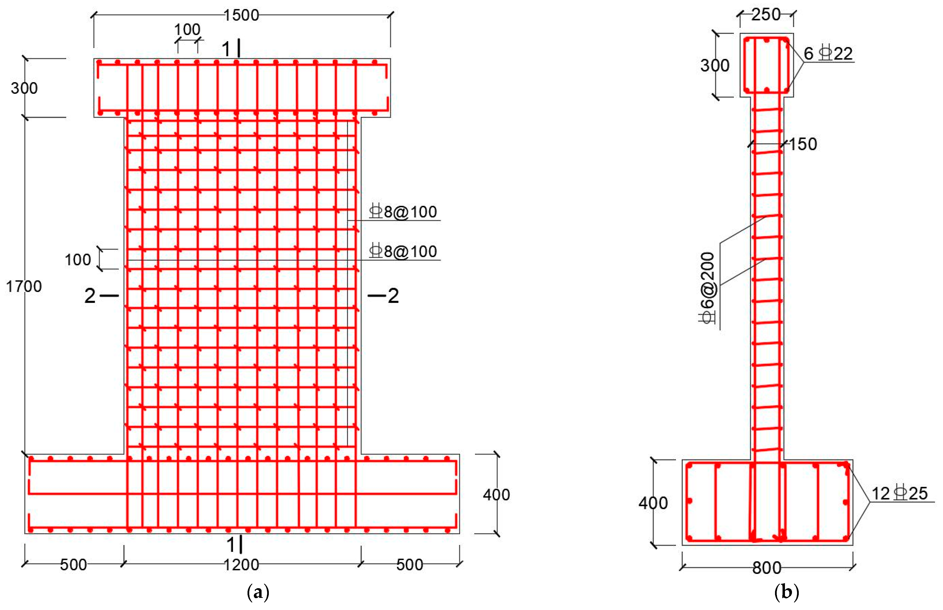
Figure 1. Size and reinforcement diagram of the blastproof partition wall (unit: mm). (a) Sectional drawing; (b) side view.
Coatings 12 01836 g001
Figure 2. FRP types. (a) FRP sheets; (b) tensile specimens.
Coatings 12 01836 g002
Figure 3. Test device and strain layout. (a) Diagram of the test device; (b) strain measuring points.
Coatings 12 01836 g003
Figure 4. Pasting modes of FRP (unit: mm): (a) 100 mm paste mode; (b) 50 mm paste mode.
Coatings 12 01836 g004
Figure 5. Destruction form of specimen. (a) Bending failure; (b) B0-0-1; (c) B0-0-2.
Coatings 12 01836 g005
Figure 6. Destruction form of pasted FRP. (a) FRP peeling failure; (b) BA2-100-1; (c) BA2-100-2.
Coatings 12 01836 g006
Figure 7. Time-history curves of impact force. (a) Specimen B0-0; (b) Specimen BC1-100; (c) Specimen BC2-100; (d) Specimen BA2-100; (e) Specimen BL1-100; (f) Specimen BL1-50.
Coatings 12 01836 g007
Figure 8. Time-history curves of mid-span horizontal displacement. (a) Specimen B0-0; (b) Specimen BC1-100; (c) Specimen BC2-100; (d) Specimen BA2-100; (e) Specimen BL1-100; (f) Specimen BL1-50.
Coatings 12 01836 g008
Figure 9. Crack measuring point and width figure. (a) Layout of crack measuring points; (b) statistical graph of crack widths.
Coatings 12 01836 g009
Figure 10. Time-history curve of steel bar strain. (a) Measuring Point 1; (b) Measuring Point 8; (c) Measuring Point 4.
Coatings 12 01836 g010
Figure 11. Parametric analysis. (a) FRP type; (b) number of FRP layers; (c) FRP width.
Coatings 12 01836 g011
Figure 12. Finite element model.
Coatings 12 01836 g012
Figure 13. Concrete and steel bar material model. (a) CSCM model; (b) steel bar hardening model.
Coatings 12 01836 g013
Figure 14. Damage comparison between finite element and experimental results. (a) Comparison of damage to the back of specimen B0-0-1; (b) comparison of damage to CFRP sheet (BC1-100-1); (c) comparison of damage to AFRP sheet (BA2-100-1); (d) comparison of damage to large-rupture-strain FRP sheet (BL1-100-1).
Coatings 12 01836 g014aCoatings 12 01836 g014b
Figure 15. Time-history comparison of impact force. (a) Specimen B0-0; (b) Specimen BC1-100; (c) Specimen BA2-100; (d) Specimen BL1-100.
Coatings 12 01836 g015
Figure 16. Time-history comparison of mid-span horizontal displacement. (a) Specimen B0-0; (b) Specimen BC1-100; (c) Specimen BA2-100; (d) Specimen BL1-100.
Coatings 12 01836 g016
Table 1. Pendulum impact parameters of blastproof partition wall.
Specimen NumberFRP Parameters
Layers (n)Width (mm)Spacing (mm)
B0-0---
BC1-1001100100
BC2-1002100100
BA2-1002100100
BL1-1001100100
BL1-50150100
Table 2. FRP sheet material properties.
Material CategoryDensity
(kg/m3)
Tensile Strength (mpa)Elastic Modulus (gpa)Tensile Strain at Break (%)Thickness
(mm)
CFRP150035402401.50.167
AFRP14402195672.20.193
LRS-FRP13847401870.841
Table 3. Properties of epoxy resin adhesive materials.
Tensile Strength
(MPa)
Flexural Strength
(MPa)
Tensile Shear Strength (MPa)Compressive Elastic Strength (MPa)Compressive Yield Strength (MPa)
3542141.5×10376
Table 4. Impact test results.
Specimen NumberImpact TimesMaximum Impact Force (kN)Maximum Mid-Span Displacement (mm)Residual Displacement (mm)Impact Recovery Factor (R)
B0-012289.240.426.90.33
22417.756.639.80.30
BC1-10012324.830.319.10.37
23035.860.842.90.29
BC2-10012249.428.617.50.39
23234.155.539.20.29
BA2-10012435.624.812.20.51
23337.149.332.40.34
BL1-10012498.130.414.40.53
22984.845.823.20.49
BL1-5012327.430.813.20.57
22870.146.231.20.32
Note: R is the impact recovery coefficient = 1 − residual displacement/maximum mid-span displacement.
Table 5. Concrete crack morphology.
Specimen numberS-1S-2S-3B-1B-2B-3
B0-0Coatings 12 01836 i001Coatings 12 01836 i002Coatings 12 01836 i003Coatings 12 01836 i004Coatings 12 01836 i005Coatings 12 01836 i006
BC1-100Coatings 12 01836 i007Coatings 12 01836 i008Coatings 12 01836 i009Coatings 12 01836 i010Coatings 12 01836 i011Coatings 12 01836 i012
BC2-100Coatings 12 01836 i013Coatings 12 01836 i014Coatings 12 01836 i015Coatings 12 01836 i016Coatings 12 01836 i017Coatings 12 01836 i018
BA2-100Coatings 12 01836 i019Coatings 12 01836 i020Coatings 12 01836 i021Coatings 12 01836 i022Coatings 12 01836 i023Coatings 12 01836 i024
BL1-100Coatings 12 01836 i025Coatings 12 01836 i026Coatings 12 01836 i027Coatings 12 01836 i028Coatings 12 01836 i029Coatings 12 01836 i030
BL1-50Coatings 12 01836 i031Coatings 12 01836 i032Coatings 12 01836 i033Coatings 12 01836 i034Coatings 12 01836 i035Coatings 12 01836 i036
Table 6. Material parameters of finite element model.
MaterialMaterial ModelMaterial Parameters
ConcreteMAT_CSCM_CONCRETE ρ = 2400   kg / m 3 , f c = 38 . 1   MPa ,   D = 25   mm
Tension steelMAT_PLASTIC_KINEMATIC ρ = 7800   kg / m 3 , E = 205   GPa , υ = 0.3 f y = 442   MPa ,   f u = 614   MPa
FRPMAT_ENHANCED_COMPOSITE
_DAMAGE
Table 2
PendulumMAT_ELASTIC E = 210   GPa , υ = 0.3
Fixture deviceMAT_RIGID ρ = 7800   kg / m 3 , E = 210   GPa , υ = 0.3
Table 7. Comparison of experimental and simulation results.
Specimen NumberPeak Impact Force (kN)Peak Mid-Span Horizontal Displacement (mm)
ExperimentalSimulationErrorExperimentalSimulationError
B0-02289.22070.39.6%40.146.014.7%
BC1-1002324.82211.04.9%30.328.65.6%
BC2-1002249.42062.58.3%28.625.311.5%
BA2-1002435.62235.88.2%24.823.55.2%
BL1-1002498.12386.24.5%30.429.33.6%
BL1-502327.42123.38.8%30.831.41.9%
Publisher’s Note: MDPI stays neutral with regard to jurisdictional claims in published maps and institutional affiliations.