Abstract
Based on the analysis of the correlation between plasma glow and the magnetic field over a magnetron target, a model for predicting the shape of the target erosion of MSS is proposed. The magnetic field distribution is obtained upon direct measurement or calculation using the ELCUT software, which allows one to calculate the magnetic field based on the magnetron model. A special software has been developed for the calculation of the depletion profile of a target in a planar MSS. It allows one to predict the target erosion during the design phase of MSS, thus reducing the efforts required for designing a multi-magnet system of magnetron. The software has to be tested by comparing the calculated profile of the target erosion with the real one for different types of MSS.
1. Introduction
At present, the use of magnetron sputtering systems (MSS) is finding ever-expanding fields of application [1,2,3,4,5]. The key to the success of sputter deposition is its scalability, enabling from lab-scale to high-throughput large-area film deposition [6]. The disadvantage of MSS is the low utilization of the sputtering target material. The design of magnetic parts of modern MSS is often the cause of inhomogeneous sputtering of the material from the target surface; the plasma confinement in front of the target results in inhomogeneous target erosion [6,7,8].
The parameter that describes the shape of the erosion profile is the target utilization factor (TUF), denoted as F [9,10,11,12]:
where m0 is the initial mass of the target and mT is the mass of the target during its disposal.
The mass of the sputtered target material is determined by the width and shape of the erosion groove of the target. The values of F for typical magnetrons are in the range of F = 10%, …, 25%. When using targets made of non-precious metals, the F value is often not of much importance. With the use of standard metal targets, the value of F is often irrelevant, which makes its reuse after remelting possible. When using ceramic targets sintered from expensive metastable powder mixtures, the use of MSS with maximum consumption efficiency of the target material is of great significance. Such items include, for instance, B4C targets enriched with 10B isotopes that are used in neutron detectors. Such types of target cannot be used more than once. As shown in [1,2], F primarily depends on the magnetic system of the magnetron. The improvement of the magnetic system of the magnetron can make it possible to achieve the value F = 65%, … , 80%. In this case, the width of the erosion groove is close to the width of the target and is Π-shaped. The extension of the erosion groove increases the area of the sputtering source on the target, enhancing the homogeneity of the obtained film layer. Moreover, the lifetime of the target increases and the cost per film layer decreases.
In [10], to predict the shape of the target erosion, a calculation method was proposed based on the following assumptions:
- ➢
- The lower boundary, y0, of the ionization area (magnetron discharge area) is determined by the dark cathode space;
- ➢
- The upper boundary, ymax, of the ionization area is limited by the value of Bx (component of the magnetic induction B, parallel to the target surface, equal to 0.02 T);
- ➢
- The concentration factor, ne(x,y), of electrons ionizing the working gas in the entire plasma volume is considered to be a constant value;
- ➢
- The number of ionization events in the space of the ionization area is proportional to the electron drift velocity and is determined by the quantity, .
Under the assumptions mentioned above, the authors believe that the profile, h(x), of the target erosion depth is defined by:
For computer simulation of this model, the authors propose to use a program for simulating and calculating the magnetic field [10], with the help of which the distribution of magnetic induction B and its component Bx over the target surface can be calculated using the dimensions of the structure of the magnetron and magnetic system. Based on the values of B and Bx, using Equation (2), a 2D matrix can be calculated, the summation of the columns of which gives the predicted erosion profile of the target, presented in relative units to simplify calculations. It has been reported [10] that the discrepancy between the calculations and the experiment was up to 25%, which was explained by the fact that the initial model for the magnetron discharge underlying Equation (2) only remotely corresponded to reality. The aim of the present work is to build a simple but more accurate computational model of a magnetron discharge (based on experimental and theoretical data) to predict target erosion for planar magnetron designs.
2. Materials and Methods
2.1. Basic Physical Principles
MSS are a type of sputtering system based on a glow gas discharge in anomalous discharge mode, containing a magnetic system that holds plasma electrons at the cathode for multiple collisions of electrons with working gas atoms up to the maximum expenditure of electron kinetic energy for ionization of working gas atoms. The confinement of electrons in a closed area of crossed electric and magnetic fields occurs due to the Lorentz force, which makes the electrons move parallel to the target cathode surface along cycloid closed trajectories, producing a closed Hall current in the drift approximation. Planar MSS have a tunnel-like closed magnetic field, with an arched cross section (Figure 1), in which only the upper part of the arch has an area where the magnetic induction vector is parallel to the cathode surface. Because the electric field is directed perpendicular to the surface, this shape of magnetic field affects electrons differently, which results in a non-uniform density of ionizing electrons and, accordingly, in a non-uniform density of ions in the working gas, which produce non-uniform sputtering of the target cathode. Observations show that the configuration of the magnetic field, the distribution of the brightness of the discharge plasma glow, the current density over the cathode surface, and the sputtering (erosion) of the target cathode are interrelated. In Figure 1 [11] this interrelation can clearly be seen.
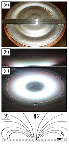
Figure 1.
Interrelation between the shape of erosion of the magnetron target with the plasma glow and the magnetic field configuration: (a) photograph of an eroded target; (b) glowing plasma from the end of the target; (c) an angled view of the glowing plasma; (d) the shape of the magnetic field lines in the cross section.
The analysis of Figure 1 shows that the shape of erosion is directly related to the distribution of the brightness of the plasma glow and the configuration of the magnetic field that determines the distribution of Bx. The following conclusions follow from the analysis:
- (1)
- The main processes of ionization of the working gas, which are responsible for the sputtering and erosion of the target cathode, occur in the near-surface layer;
- (2)
- The maximum brightness of the plasma glow, concentrated in the near-surface layer, coincides with the greatest depth of target erosion;
- (3)
- The boundaries of the erosion area are determined by the boundaries of the plasma glow and the boundaries of the nonzero value of Bx;
- (4)
- The erosion area can be conditionally divided into a general erosion area and an erosion groove;
- (5)
- The shape of the general erosion area is consistent with the plasma glow (without reference to the brightest plasma glow in the form of a ‘cord’) and the projection of distribution of Bx;
- (6)
- The center of the erosion groove coincides with the maximum brightness of the plasma ‘cord’ and the upper area of the near-surface dome-shaped magnetic field lines (area with B parallel to the target cathode surface);
- (7)
- The brightness of the plasma glow decreases with Bx.
Based on long-term investigations of the magnetron discharge, summarized in [11], the magnetron discharge can be divided into three characteristic areas: the cathode layer, the area of partially magnetized plasma, and the anode layer. The magnetic field, the electric field, and the characteristic areas of the plasma are schematically presented in Figure 2. In a magnetron discharge for typical MSS, B is in the range of 0.1–0.001 T.
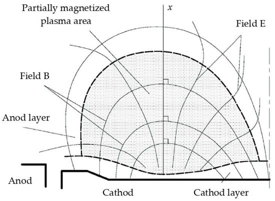
Figure 2.
Schematic layout of characteristic discharge areas in MSS.
The cathode layer starts from the surface of the target cathode. The layer thickness has a value of 0.1–10 mm and is determined by the radius of the cycloid accelerating motion of the electron, which in turn is determined by the applied discharge voltage, U, and the value of Bx. In this layer, the loss of U amounts to 80%–90%. The electric field strength reaches a value of 8 × 10⁶ V/m, which drops sharply at the edge of the layer boundary to less than 4 × 10⁴ V/m. There is no ionization of the working gas in the cathode layer due to saturation. Saturation is determined by the condition of equality of the ion current and discharge current, . This means that the discharge current transport is governed by ions. The absence of ionization processes explains the absence of luminescence; therefore, the cathode layer is called the dark cathode space (DCS). Here, the ion concentration factor has a maximum value , determined by the stability condition of the magnetron discharge:
where α = 0.001 ÷ 0.1 is the coefficient of secondary ion-electron emission, depending on the composition of the working gas and the target material and β is the coefficient of electron ionization of the working gas (due to the smallness of autoelectronic and thermionic emission, it can be neglected). Secondary electrons do not constitute the discharge current, but only ensure the stability of the discharge. Because the concentration factor of secondary electrons is determined by the expression
the electron current of the secondary electron emission occurring in DCS is less than the ion current and is determined as:
α × β = 1,
One should realize that in this area, along with the electron-ion equilibrium state of the working gas, there are atoms, molecules, and cluster formations of the cathode material knocked out of the cathode target, which undergo recharging—ionization into both charges and recombination. As for molecules, they can break down into atoms and ionize and assemble into more stable compounds with the reaction gas, whose molecules decompose, ionize, and form molecular bonds with the target material. It is in the thin cathode layer that reactive processes take place, and the ions of the working gas acquire the main energy necessary for sputtering the target by bombarding it. Magnetron sputtering is very energy intensive and amounts to about 500 eV per target atom. Therefore, for knocking atoms out of the target, the total energy spent is 15–40 eV, consisting of a threshold sputtering energy (binding energy) of 15–30 eV and the energy of sputtered atoms within 1–10 eV. The rest of the energy goes to heating the target. The voltage of the magnetron discharge is in the range of 250–800 V. With an increase in voltage, the energy of bombarding ions, as well as the sputtering coefficient, also increases, but at the same time, the process of implantation of ions into the crystal lattice of the target also intensifies, resulting in its deformation, volumetric distortion, and, as a consequence, heating of the target, which requires efficient cooling.
The area of partially magnetized plasma is adjacent to the cathode layer and begins where the ion-electron equilibrium of the working gas ends and the electrons leaving the target stop gaining energy and start to spend it on ionization. The presence of ionization explains the glow in this area. With distance from the target, the number of electrons capable of ionization decreases, reducing the number of ionization events, which explains the weakening of the plasma glow. Starting from the boundary with the cathode layer, the number of collisions is so large that the relation holds, where and are cyclotron frequencies for the electrons and ions; and are the time between collisions for electrons and ions. If this condition is met, then the equipotentials of the electric field coincide with the magnetic field lines and the relation is valid [13,14]:
which means that the electric field lines become perpendicular to the magnetic field lines.
Thus, the magnetic field has a decisive impact on the movement of electrons, but not on ions ); they move freely towards the cathode along the formed electric field lines. Therefore, this area of discharge is called partially magnetized. As the distance from the target increases, the magnetic field decreases, and these conditions, gradually weakening, disappear. This determines the boundaries of the propagation of the area of partially magnetized plasma, which are characteristic before the B attenuation of down to 0.001 T, where . Experiments show that the transition area starts where the induction decreases to a value of about 0.02 T. The thickness of this area is from 10 to 100 mm, and the voltage decrease is 10%, …, 15% of U of the magnetron discharge. The intensity of the electric field with distance from the target changes from 2∙104 V/m in the boundary layer, first rapidly decreasing, then decreasing more and more smoothly, and approaches values close to zero. A feature of this area is the occurrence of two oppositely directed flows of charged particles: the flow of ions produced during ionization of the working gas by electrons and the flow of electrons knocked out of gas atoms during ionization, which together with ions make up the discharge current, and high-energy secondary electrons, the energy of which decreases with distance from the target cathode. Therefore, unlike the produced gas ions that freely start accelerated motion along the electric field lines towards the cathode, the electrons are retained by the influence of a magnetic field that makes them move along cycloid trajectories across the target surface. The movement towards the anode occurs only upon collision with gas atoms, which leads to the electron jumping to more distant trajectories from the target. If the electron energy is sufficient for ionization, then the jump and ionization of the atom occurs; if the electron energy is insufficient for ionization, then the jump occurs as a result of an elastic collision. Therefore, at the interface with the anode layer, the plasma current mainly consists of electrons, and at the interface with the cathode layer, it consists of ions.
The anode layer is directly adjacent to the anode and serves for transporting electrons to the anode. The voltage drop across the anode layer is small and amounts to about one or two ionization potentials of the working gas; for argon it is about 15…30 V. The discharge current in the anode layer is carried by electrons.
2.2. Mathematical Model and Software Implementation
To mathematically describe the shape of target erosion, we place the coordinate system in the plane of the arched magnetic field (Figure 1d) and choose the origin O to be located at the center of the magnetron target so that the Ox axis is directed along the target surface and the Oy axis is perpendicular to the surface. Secondary electrons emitted perpendicular to the target plane, under the influence of an electric field, move with acceleration parallel to the Oy axis; the magnetic field deflects electrons perpendicular to the xOy plane along a cycloid, the radius of which is determined by
where m = 9.1 × 10⁻³¹ kg, e = 1.6 × 10⁻⁹ C. Assuming that the height d of DCS is equal to r, we calculate d from the values of Bx and
In the cross section under consideration, the accelerated electrons enter the area of the partially magnetized plasma parallel to the Oy axis. Due to very frequent ionizing collisions of electrons, the electric field changes its configuration and becomes perpendicular to the magnetic field lines. The separation of electrons occurs; some of them move perpendicular to the magnetic field lines, and the rest move along the lines. The number of the former, held by the influence of the magnetic field, which leads to rotation around the circle, depends on the angle between the electron velocity vector and the magnetic induction vector, which is determined by the ratio Bx/B. These electrons cause ionization of the area of partially magnetized plasma and form an erosion field, the depth of which depends on the number of captured electrons, and the relative depth, he, is determined by
where n(x,y) is the concentration factor of ionization events. The other parts of the electrons flow along the magnetic field lines to the upper point of the dome-shaped field, where the induction vector is parallel to the target surface. As a result, a large number of electrons are concentrated in the upper area of the dome, the distribution density of which obeys the Gaussian distribution. Ionization produced by these electrons is responsible for the formation of an erosion groove, the width of which is determined by the current density of the magnetron discharge, and the depth is determined by the number of captured electrons. The relative profile depth, , of the groove is determined by
where is the distribution variance obtained, depending on the density of the magnetron discharge, and is characterized by the permissible angle of deviation of the induction vector from the cathode surface. The distribution of the concentration of ionization events is proportional to the change in induction, more precisely, its component that holds electrons:
The final erosion profile is determined by the normalized sum of the normalized profile of the erosion groove and the normalized profile of the erosion area, multiplied by the selected coefficient k, which varies from 0.1 to 0.8 and shows the proportion of confined electrons from their total number depending on the magnetron discharge current density (electric power supplied to the magnetron):
The software implementation of the described model for calculating the predicted erosion profile of a magnetron target is called the Pretarger calculation program (Prediction of target erosion) and is written in MATLAB. The input data of the program are data in the form of text tables of distribution of the magnetic field induction B(x,y) and its components Bx(x,y) and By(x,y) over the target surface. The functionality of the program includes the calculation of erosion profiles of the target material of planar-type magnetron sputtering systems of any size and design. The Pretarger program converts input tables into data matrices, performs calculations using the above formulas, and outputs the h(x) profile graph of the predicted erosion of the target. Input data in the form of tables can be compiled either via direct measurements of the magnetic field distribution using a magnetometer, or by using a magnetostatic simulation program and calculating physical fields according to the design model of the magnetron and its magnetic system. The software package ELCUT (version 6.4) [15], based on the simulation of physical fields using the finite element method, was chosen as such a program. At the same time, ELCUT objects provide the formulation of a new problem, the description of its geometric model, the construction of a finite element grid, and its solution. The use of ELCUT is especially helpful at the stage of designing new magnetrons. For the convenience of entering data obtained using ELCUT into the Pretarger program, a data transfer script has been developed.
3. Results
As an example, the calculation of the predicted erosion profile of a dual MSS target was performed. Its schematic is shown in Figure 3. The design of the magnetron (44 × 158 × 438 mm) includes: 1—base (133 × 413 mm) made of steel (A570(36)); 2—peripheral magnets (20 × 25 × 45 mm) made of NdFeB N48H with an induction coercive force of 1353 kA/m and a residual magnetic induction of 1.36–1.42 T; 3—central pole piece in the shape of match bars made of steel (A570(36)); 4—target (6 × 120 × 400 mm); 5—central clamp and 6—peripheral clamp of the target; 7—shield under floating potential; 8—body made of duralumin aluminum alloy; 9—holder grounded to the chamber body and isolated from the magnetron. Two identical magnetrons form a dual sputtering system. Power relative to the body is alternately supplied to the cathodes of the magnetrons, galvanically isolated from all other parts.
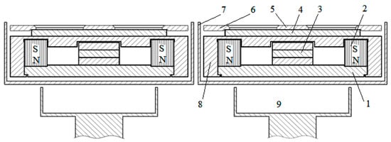
Figure 3.
Schematic of the dual MSS. Legend see in the text.
In view of the symmetry, using the ELCUT software package, the configuration and distribution of the magnetic field was calculated for the left magnetron (Figure 4a). The magnetic system has a pronounced imbalance of the 2nd type inherent in the design, due to the absence of a central magnet and a strong lateral field. The predicted erosion profile calculated using the Pretarger program for the case of one and three bars of the central pole piece is presented in Figure 5a. Strong mutual distortions of the magnetic field, leading to uneven erosion, associated with a number of placed magnetrons, are significantly weakened when using a shield made of steel (A570(36)). The configuration and distribution of the magnetic field with a shield is shown in Figure 4b and the predicted erosion profile is presented in Figure 5b. However, the use of a magnetic shield closes the lateral magnetic field on itself, which leads to its weakening and forms areas where parasitic plasma can occur. The characteristic dimensions of the predicted erosion profile with one or three bars of pole pieces for each magnetron in a dual MSS, and the influence of the magnetic shield are presented in Table 1.
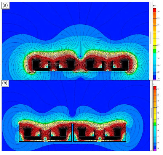
Figure 4.
Configuration of the magnetic field of the dual system of magnetrons: (a) from two identical magnetrons; (b) using a magnetic shield.
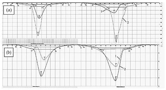
Figure 5.
Predicted erosion profile for the left magnetron of the dual system of magnetrons with 1—3 bars, 2—1 bar; (a) dual magnetron without a magnetic shield; (b) dual magnetron with a magnetic shield.

Table 1.
Predicted erosion profile for the left magnetron of the dual system. All values are mm.
4. Conclusions
Based on the published data summarizing numerous observations of the operation of magnetrons, a simplified model of the complex processes occurring in a magnetron discharge is proposed. Semi-empirical formulas are derived for calculating the predicted shape of the target erosion profile of planar magnetrons of various designs, based on knowledge of the configuration of the magnetic field and the distribution of the B value and its components relative to the target surface.
A program has been developed for predicting the erosion profile of the magnetron target Pretarger. It allows one to predict the target erosion at the stage of designing the MSS. It is implemented in MATLAB and provides the possibility to input data on the distribution of the magnetic field over the target surface, which are calculated from the model of the magnetron and its magnetic system using the ELCUT software package.
For the first time, to the authors’ knowledge, the predicted erosion profile has been calculated for a dual MSS assembled from two identical magnetrons. A comparison of the calculations with real erosion is planned.
In order to obtain convincing results on the accuracy of predicting the erosion of the magnetron target, it is necessary to develop a test stand for measuring the distribution of the induction value and its components over the target, as well as test out the program to obtain statistical results of comparing the predicted erosion with the developed targets for various planar magnetrons. The implementation of the possibility of taking into account the external electric field in the Pretarger program will allow predicting the erosion profile of the target, taking into consideration the shape of the anode, as well as how it is positioned.
In order to increase the value of F and the efficiency of the magnetron, the assembling of multi-magnet systems is required. The additional magnets should produce magnetic fields opposite or at an angle of 90 degrees to the magnetic fields of the basic magnets of the magnetron. In this case, the area where the magnetic induction is parallel to the surface of the target will be increased. Such magnetic systems can be calculated using software such as ELCUT.
Author Contributions
A.K. and Y.K. developed the software; A.K. performed the formal analysis; A.K., M.G. and V.B. wrote, discussed, and edited the manuscript; V.B. was responsible for funding acquisition. All authors have read and agreed to the published version of the manuscript.
Funding
The results were obtained with the financial support of the Russian Federation, represented by the Ministry of Science and Higher Education, agreement No. 075-10-2021-115 dated 13 October 2021 (internal number 15.SIN.21.0021).
Institutional Review Board Statement
Not applicable.
Informed Consent Statement
Not applicable.
Data Availability Statement
The data presented in this study are available on request from the corresponding author.
Conflicts of Interest
The authors declare no conflict of interest.
References
- Padamata, S.K.; Yasinskiy, A.; Yanov, V.; Saevarsdottir, G. Magnetron sputtering high-entropy alloy coatings: A mini-review. Metals 2022, 12, 319. [Google Scholar] [CrossRef]
- Hou, S.; Yu, W.; Yang, Z.; Li, Y.; Yang, L.; Lang, S. Properties of titanium oxide coating on MgZn alloy by magnetron sputtering for stent application. Coatings 2020, 10, 999. [Google Scholar] [CrossRef]
- Graziani, G.; Barbaro, K.; Fadeeva, I.V.; Ghezzi, D.; Fosca, M.; Sassoni, E.; Vadalà, G.; Cappelletti, M.; Valle, F.; Baldini, N.; et al. Ionized jet deposition of antimicrobial and stem cell friendly silver-substituted tricalcium phosphate nanocoatings on titanium alloy. Bioact. Mater. 2021, 6, 2629–2642. [Google Scholar] [CrossRef] [PubMed]
- Surmenev, R.A.; Ivanova, A.A.; Epple, M.; Pichugin, V.F.; Surmeneva, M.A. Physical principles of radio-frequency magnetron sputter deposition of calcium-phosphate-based coating with tailored properties. Surf. Coat. Technol. 2021, 413, 127098. [Google Scholar] [CrossRef]
- Qadir, M.; Li, Y.; Wen, C. Ion-substituted calcium phosphate coatings by physical vapor deposition magnetron sputtering for biomedical applications: A review. Acta Biomater. 2019, 89, 14–32. [Google Scholar] [CrossRef] [PubMed]
- Cordill, M.J.; Kreiml, P.; Mitterer, C. Materials engineering for flexible metallic thin film applications. Materials 2022, 15, 926. [Google Scholar] [CrossRef] [PubMed]
- Gudmundsson, J.T. Physics and technology of magnetron sputtering discharges. Plasma Sources Sci. Technol. 2020, 29, 113001. [Google Scholar] [CrossRef]
- Wasa, K.; Kanno, I.; Kotera, H. (Eds.) Handbook of Sputter Deposition Technology: Fundamentals and Applications for Functional Thin Films, Nano-Materials and MEMS; William Andrew: Norwich, NY, USA, 2012. [Google Scholar]
- Goncharov, A.A.; Brown, I.G. Plasma devices based on the plasma lens—A review of results and applications. IEEE Trans. Plasma Sci. 2007, 35, 986–991. [Google Scholar] [CrossRef]
- Golosov, D.A.; Melnikov, S.N.; Kundas, S.P.; Dostanko, A.P. Prediction of target erosion in magnetron sputtering systems. Probl. Phys. Math. Tech. 2010, 2, 62–67. (In Russian) [Google Scholar]
- Dukhopelnikov, D.V. Magnetron Sputtering Systems. P. 1.; Bauman University: Moscow Russia, 2014. (In Russian) [Google Scholar]
- Rausch, M.; Sabag, A.; Pichler, K.-H.; Gruber, G.C.; Köstenbauer, J.; Köstenbauer, H.; Kreiml, P.; Cordill, M.J.; Winkler, J.; Mitterer, C. The sputter performance of an industrial-scale planar Mo-target over its lifetime: Target erosion and film properties. Surf. Coat. Technol. 2020, 381, 125174. [Google Scholar] [CrossRef]
- Grishin, S.D.; Leskov, L.V.; Kozlov, N.P. Electric Rocket Motors; Mashinostroenie: Moscow, Russia, 1975; p. 272. (In Russian) [Google Scholar]
- Morozov, A.I. Physical Phoundation of Space Ionic Engines. Elements of Flow Dynamics in IE; Atomizdat: Moscow, Russia, 1978; p. 328. (In Russian) [Google Scholar]
- Available online: http://www.tor.ru/elcut/ (accessed on 23 April 2020).
Publisher’s Note: MDPI stays neutral with regard to jurisdictional claims in published maps and institutional affiliations. |
© 2022 by the authors. Licensee MDPI, Basel, Switzerland. This article is an open access article distributed under the terms and conditions of the Creative Commons Attribution (CC BY) license (https://creativecommons.org/licenses/by/4.0/).