Article

Carbon/Graphite Sheets/PTFE-Coated Porous Titanium as the Bipolar Plate by Hydrothermal Treatment

1
School of Material Science and Engineering, Jiangsu University of Science and Technology, Zhenjiang 212003, China
2
College of Communication and Electronics, Jiangxi Science and Technology Normal University, Nanchang 330038, China
*
Author to whom correspondence should be addressed.
Coatings 2022, 12(11), 1649; https://doi.org/10.3390/coatings12111649
Submission received: 9 October 2022 / Revised: 22 October 2022 / Accepted: 26 October 2022 / Published: 31 October 2022
(This article belongs to the Special Issue Research on Novel Energy Storage Materials and Devices)

Abstract

:
A multilayered carbon–-Polytetrafluoroethylene/graphite sheet (C-PTFE/GS) coating is synthesized on a Ti plate by hydrothermal and immersion method. The innermost layer is composed of amorphous carbon and the outermost layer is made of a compound with PTFE, graphite sheets and nanotube. Interfacial contact resistance (ICR) decreases to 8.9 mΩ·cm−2 at the applied force of 1.4 MPa between carbon paper and the substrate with coating. The corrosive current density is only 0.49 μA/cm2 at the cathode, while the potential of 0.6 V is applied. The charge transfer resistance of the multilayer carbon coating is higher than that of a bare sample through the results of electrochemical impedance spectroscopy. Moreover, there are no obvious changes in the coating before and after potentiostatic polarization testing by X-ray photoelectron spectroscopy (XPS) analysis, which demonstrates the stability of multilayered C-PTFE/GS coating on Ti. In addition, the surface morphology of C-PTFE/GS coating is preserved without defect after potentiostatic polarization in a simulated environment of proton exchange membrane fuel cells (PEMFCs). Therefore, the C-PTFE/GS coating is potentially applied as bipolar plates in PEMFCs.

1. Introduction

The main component of PEMFCs was composed of bipolar plates, membrane electrodes assembly (MEA) [1] and the gas diffusional layer [2]. The functions of bipolar plates were used to separate the gas of redox, collect the electricity and eject the water by reaction of hydrogen and oxygen. The 60%–80% of mass and almost all of the volume were taken up by bipolar plates. The key points were to develop excellent conductivity, low cost and weight and good anti-corrosion of bipolar plates [3]. The early research on coating of the metal bipolar plates of PEMFCs mainly adopted the precious metal coating, such as Pt [4], Ag [5], Ti–Pt [6] and Ni–P [7]. Although the obtained coatings showed excellent corrosion resistance and electrical conductivity, the carbide and nitride compound of Ti, Cr and Zr have been applied to minimize the fabrication cost and enhance the corrosion resistance of bipolar plates [8]. Wang et al. [9] studied three kinds of nitride coatings, TiN, TiAlN and CrN by magnetron sputtering, which demonstrated the low interface contact resistance and good protection of CrN coating on Ti. Wan et al. [10] studied the electrodeposition of CrC on the surface of 304 stainless steel. The ICR and corrosion resistance were further improved compared with the CrN coating, which can meet the requirement of a fuel cell. However, the interface adhesion with matrix still requires improvement by the method of electrodeposition. Zhang et al. [11] prepared a multi-layer CrN/Cr coating by magnetron sputtering. The Cr coating showed excellent corrosion resistance and electrical conductivity and ICR. However, Cr3+ ions produced by Cr coating after corrosion can poison the membrane. In order to solve ion contamination in the solution, the carbon gradient coating amorphous carbon (α-C/Cr) was used to block the infiltration of corrosive liquid into the substrate [12]. The corrosion current density was 0.276 µA·cm−2, which met the requirement of the U.S. Department of Energy (less than 1 µA·cm−2). Yi [13] and Feng et al. [14] also found that amorphous carbon coating (α-C) was a low degree of graphitization with a small amount of carbon and oxygen compounds. The microstructure was composed of the C-sp2 hybrid and C-sp3 hybrid, which exhibited good conductivity and corrosion resistance [15]. Therefore, the metal bipolar plate modified by amorphous carbon became the key research direction in the application. Compared with the precious metal coating, carbon coating has a reasonable price and hydrophobicity. There was no pollution to the membrane electrode and little impact on the environment [16].
The study of carbon film coating can be classified in two directions. One aspect was the preparation method of carbon coating, such as the expanded graphite flake graphite pieces in a row manufactured by Wang et al. [17]. The resin and conductive fillers were the main components of flake graphite. However, the ICR of the coating was 150 mΩ·cm2 under the loading force of 200 N·cm−2, which does not satisfy the requirement of electrical conductivity. The PVD methods have also been applied by many researchers to prepare the carbon coatings. The carbon coating prepared by magnetron sputtering has excellent corrosion resistance and electric conductivity [18]. The metal and carbon coatings were prepared by PVD under different vacuum degrees and accelerating voltages [19]. An increase in vacuum degree could improve the coating density and corrosion resistance of coated bipolar plates, but this generally requires more delicate instruments, signifying a suitability with small samples and hence, a high fabrication cost. Another direction was the structural design of carbon coating. Bi et al. [20] prepared a C/Zr-C/SS gradient coating by magnetron sputtering. The corrosion of the substrate did not occur after the test of potentiostatic polarization. Lin et al. [21] also used Ti as the intermediate layer to improve the anti-corrosion of the metal bipolar plate with coating. Therefore, Ti, Zr and other metals of corrosion resistant were added as the transition layer to achieve the isolation and protection effect of the substrate and corrosive solution, which is conducive to improve the corrosion resistance of a metal bipolar plate.
Our previous works focused on coating with the addition of different conducting particles. TiN particles were added into an electroless plating Ni–P coating in order to improve the conductivity of the coating [22]. The PTFE was added into the coating as hydrophobic materials to improve anti-corrosion [23]. The TiN and PTFE were used to disperse in the solution of Ni–P electroless plating to enhance the conductivity and anti-corrosion [24]. The simple hydrothermal method was used to prepare composite coating with C, TiN and PTFE on the Ti substrate [16]. It was important to utilize the reaction of C-F2 groups with C and oxygen-containing functional groups to improve the properties of C coatings. PTFE was used to improve the anti-corrosion as an insulator; additionally, graphite sheets were stacked by large amounts of graphene to enhance the conductivity [25].
A Ti transition layer, or a carbon coating on Ti substrate, had more excellent corrosion resistance. Therefore, Ti was selected as the base material to prepare a low-cost and excellent multilayer carbon coating, which could reduce the manufacturing cost of bipolar plates and enhance corrosion resistance and hydrophobicity. Here, the method of hydrothermal and impregnation was used to prepare the carbon−PTFE/graphite sheet composite coating on TA2 (industrial, pure titanium). The morphology, electrochemical properties, hydrophobicity and conductivity properties of composited coatings were considered carefully. The effect of PTFE, ultrathin graphite sheet and CNT of the coatings on corrosion resistance and interfacial contacting resistance was also discussed.

2. Experimental

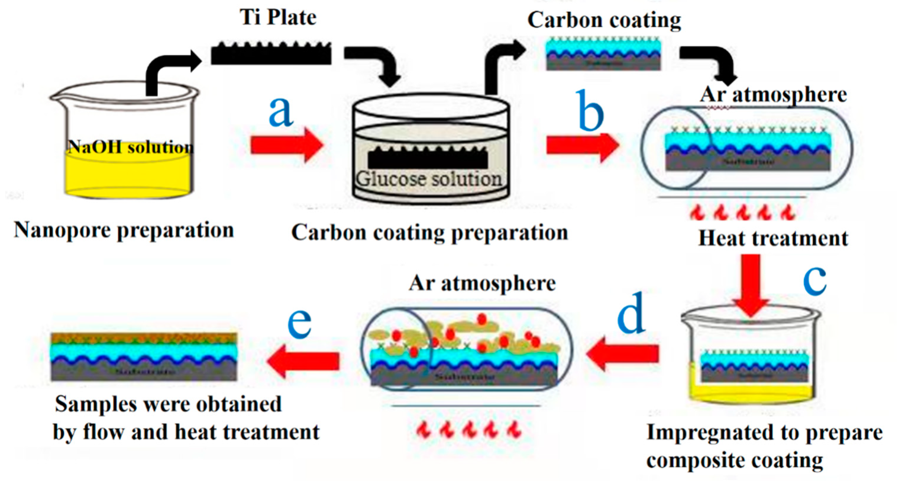
2.1. The Preparation of Bipolar Plates

Commercial pure titanium (TA2) was used as a substrate of the metal plate (XiangTou Gold Sky Ti metal Corp.). Its composition (wt.%) was 0.3 Fe, 0.15 Si, <0.2 O, <0.1 C, <0.05 N, <0.015 H, Ti balance. The Ti sheets were machined into samples of 20 mm × 20 mm × 0.2 mm. Firstly, the Ti surface was ultrasonically cleaned in acetone for 10 min and washed in distilled water. Then, the Ti plate was etched in 8 M NaOH solution for 24 h to create a porous surface structure for C deposition. The specimens were then ultrasonically cleaned in acetone, followed by distilled water before hydrothermal treatment at 170 °C for 10 h to create the carbon coating. The concentration of glucose solution was 0.1 mol/L (C6H12O6·H2O ≥ 98.0%). All chemicals were purchased from China National Pharmaceutical Group Chemical Testing Co., Ltd. (Shanghai, China).

2.2. The Preparation of Composite Coating

Carbon nanotubes (CNT) (20 wt.%) and graphite sheet (80 wt.%) were mixed to form colloids (China National Pharmaceutical Group Chemical Testing Co., Ltd., Shanghai, China). About 1 wt.% of PTFE was mixed into the above solution by ultrasonication. The Ti plates were immersed into the above suspension solution in autoclave for 2 h at 150 °C. Then, the Ti plates were taken out and dried at 80 °C. The impregnation was repeated five times to guarantee a dense protective coating layer. The solutions applied in this work are listed in Table 1. The obtained coating was eventually sintered in a tube furnace at 350 °C under an Ar atmosphere for 2 h. The schematic diagram for the preparation of coating is shown in Figure 1.

2.3. Surface Characterization
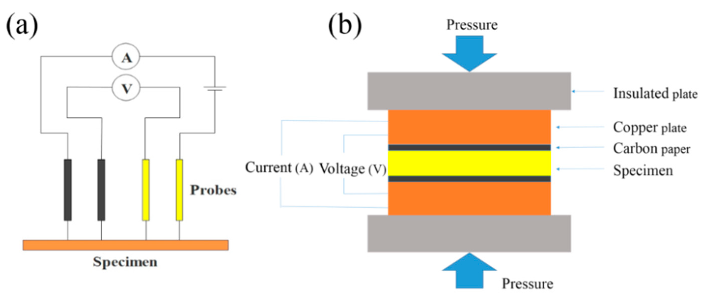
The morphology of coatings was measured by scanning electron microscopy (SEM JEOL.ISM-7600F; Akishma, Japan) under 100 kV with an analysis of the element by energy-dispersive X-ray spectrometry (EDX, Seron AIS 2300). Transmission electron microscopy (TEM, JEM-2100F; Akishima, Japan) was used to analyze the corrosive product under 120 kV. X-ray photoelectron spectroscopy (XPS) was used to character the molecular bond under Al Ka with a power of 15 kW (ThermoFisher Scientific, Waltham, MA, USA). The wettability of the surface of the coatings was studied by measurement of the static contact angle. Three different locations of coatings were chosen to measure the contact angles on each coating. The average values of contact angles were obtained with standard deviation.

2.4. Conductivity

The conductivity of the sample was characterized by surface contact resistance and interface contact resistance (ICR), as shown in Figure 2a. The surface contact resistance was measured using a four-probe meter. The surface contact resistance was tested by using SZT-C while applying the fast, constant pressure. Measurements were repeated five times and the average value was obtained for each contact interface resistance. For the through-plane conductivity (Figure 2b), samples were sandwiched by two pieces of carbon paper. Two copper plates insulated with a resin plate were employed to apply different clamping pressures and detect the potential drop/current variation in each measurement.

2.5. The Properties of Electrochemistry

A three-electrodes workstation (CHI660e; Shanghai Chenhua Instrument Co., Ltd., Shanghai, China) was used to characterize the electrochemical measurement. Testing of potentiodynamic polarization and electrochemical impedance spectroscopy (EIS) was conducted by the three-electrode system. In this experiment, 0.5 mol/L sulfuric acid (H2SO4) was mixed with 2 ppm hydrofluoric (HF) in the simulated environment of PEMFCs under 70 °C. The samples were enclosed by epoxy resins to leave one plain with an exposed square area of 1 cm2 as the working electrode. The scan rate was 1 mV/s with voltage from −0.8 to 0.8 V. A saturated calomel electrode (SCE) and Pt sheet were used as a reference electrode and counter electrode, respectively. Potentiostatic polarization was conducted for 5 h at 70 °C in such a simulated solution, while bubbling air at a potential of 0.6 V (vs. SCE).

3. Results and Discussion

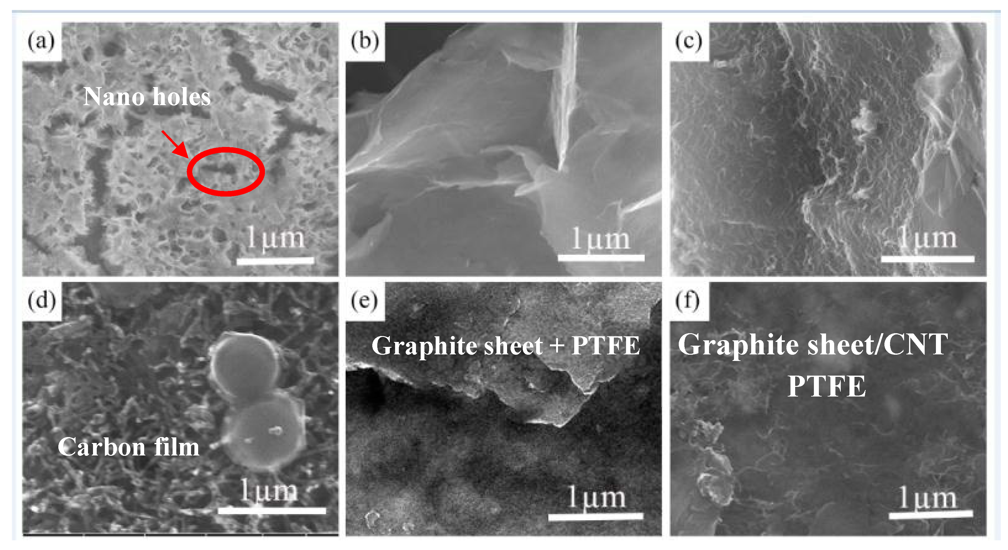
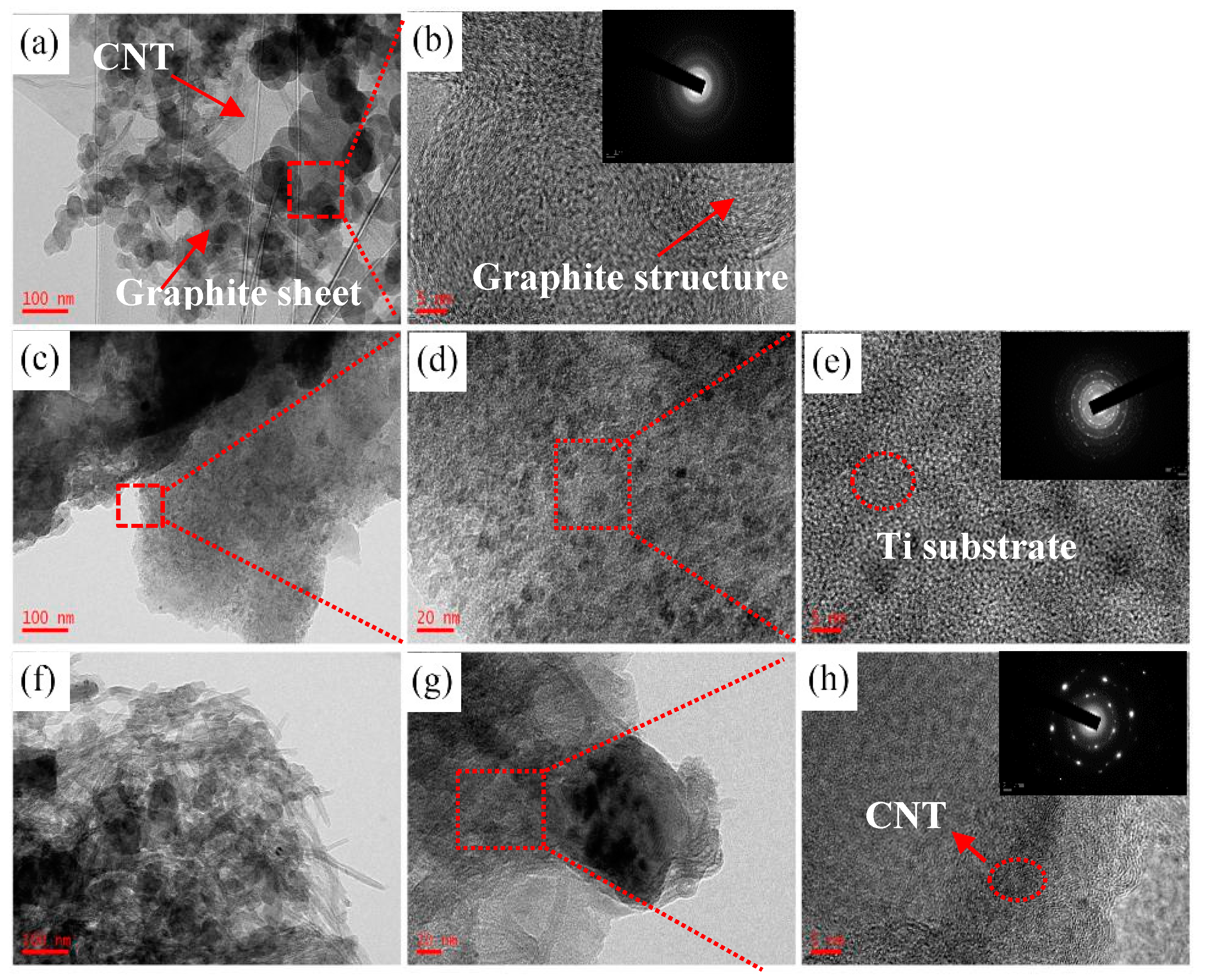
3.1. Microstructural Characterizations of the Coatings

Figure 3 shows the SEM surface morphology of Ti plates prepared in this work. The morphology of pure Ti etched by 8 mol/L NaOH solution is shown in Figure 3a. A porous network was formed on the Ti plates after etching. The pores and crack appeared on the Ti plates after etching. The nanopores on the surface of the substrate will benefit the adhesion of the carbon coating. The mechanical riveting of the coating could be achieved by the interlock between the porous surface of Ti and carbon.
Figure 4a shows the TEM image of the graphite sheet mixed with CNT coated on the substrate. The structure of graphite sheet is mainly amorphous, which is confirmed by the diffraction ring in Figure 4b. Figure 4c–e shows the composited carbon coating modified by the graphite sheet, carbon and PTFE. The amorphous structure of the carbon coating is shown by the diffraction ring in Figure 4e. The coating is well connected with titanium interface. Figure 4f–h shows the composited carbon coating modified by the graphite sheet, carbon nanotube and PTFE. The graphite carbons were amorphous. The CNT had obvious lattice characteristics.

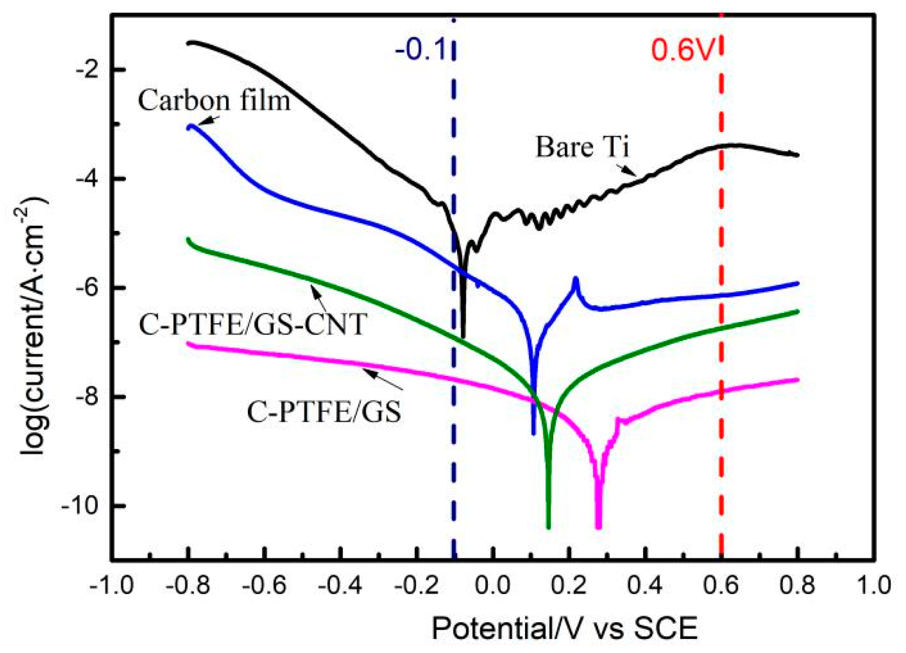
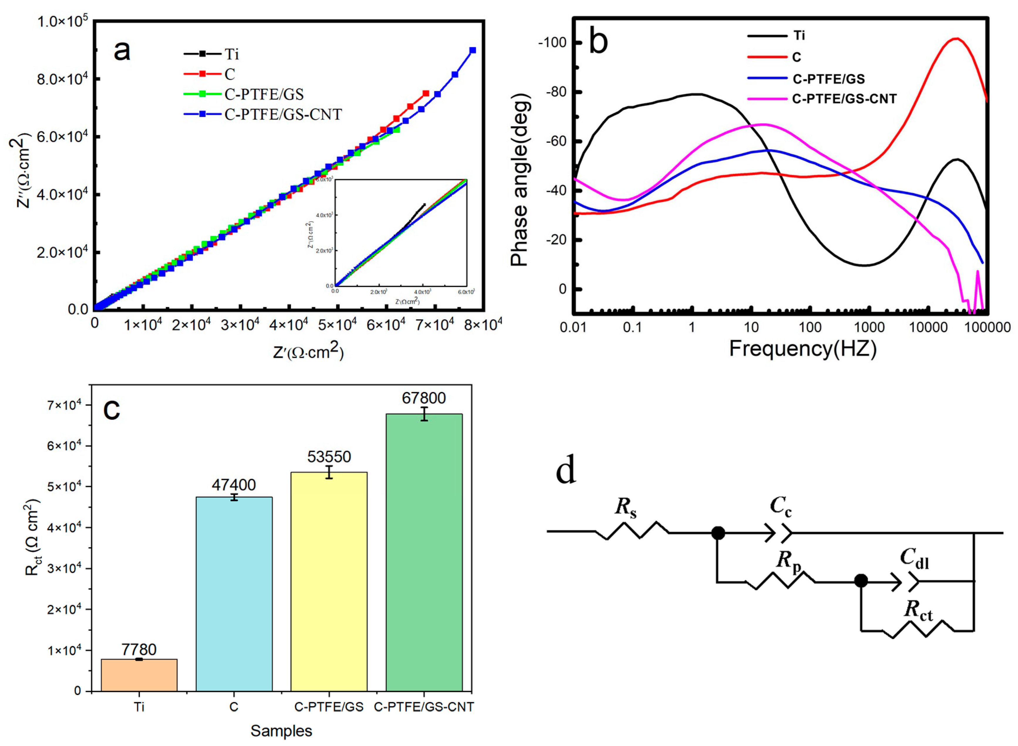
3.2. Evaluations of Electrochemical Corrosion

Figure 5 presents the potentiodynamic polarization behavior of the uncoated and the coated Ti plate immersed in the 0.5 M H2SO4 and 2 ppm HF aqueous solution with bubbling, saturated air at 70 °C. The dash line in Figure 5 presents the typical anode potential (0.6 V vs. SCE) and cathode potential (−0.1 V vs. SCE), which are used as data extrapolations to simulate working condition of PEMFCs. The corrosion potential (Ecorr) and corrosion current density are summarized in Table 2. In Figure 5, typical active–passive behaviors are shown in the curves of polarization. The sharp change from activated state to passive state was an indication of good stability of the coating on the substrate as the increase in potential. Obviously, corrosion potential of all samples shifted toward positive after surface modification. Meanwhile, a decrease in corrosion–current–density could be observed, showing a decreased corrosion rate. Among these samples, the best corrosion resistance (a current density of 0.006 µA/cm2) was noted for sample C-PTFE/GS. The current density, at a potential of −0.1 and 0.6 V, demonstrated a similar tendency as the application of composite coating. The improved corrosion resistance at potentials simulating working condition of PEMFCs is an indicator of improved durability of modified bipolar plates, which matches well with the inference from SEM observations.

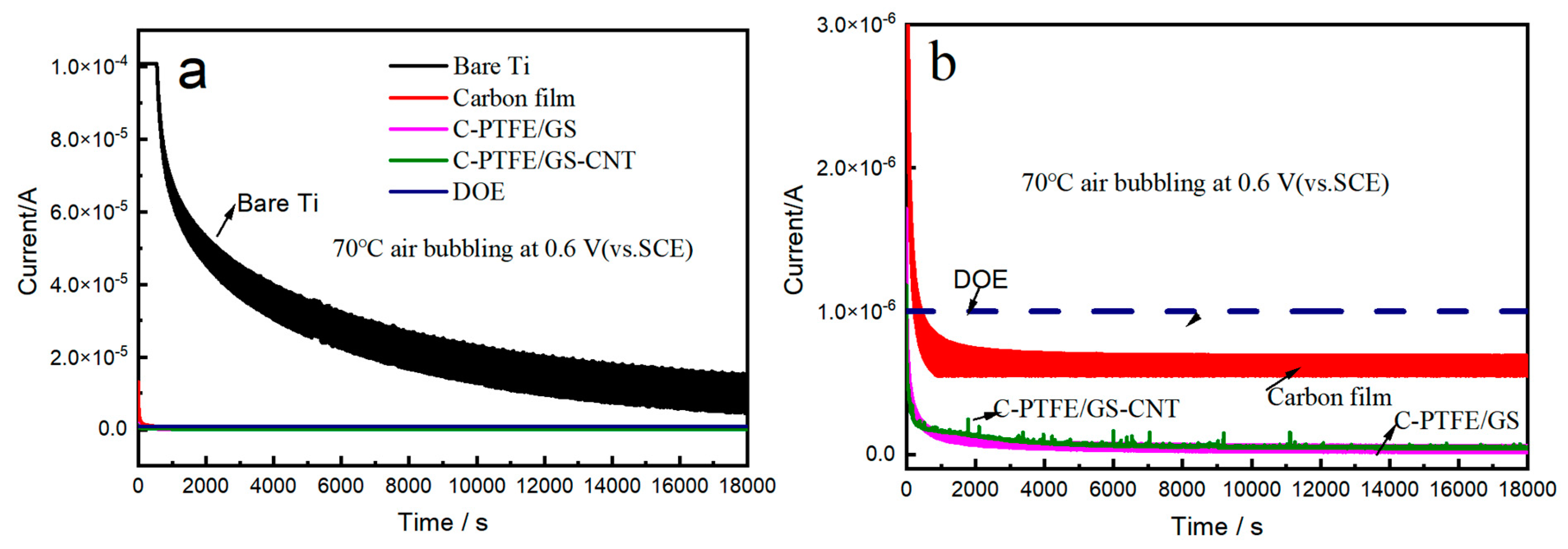
3.3. Potentiostatic Polarization
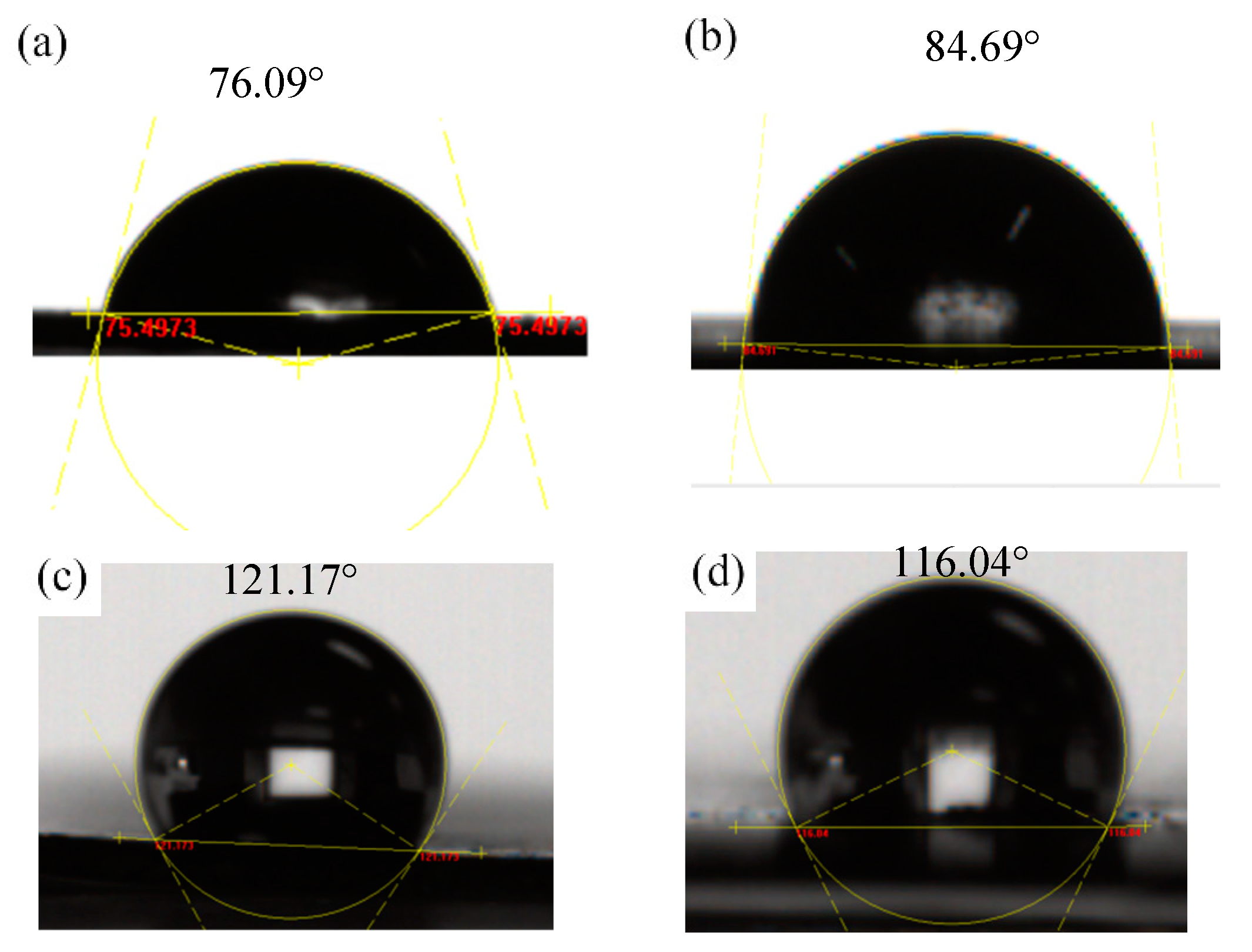
The potentiostatic polarization tests also show that the composite carbon coatings are very effective on protecting Ti substrate from corrosion under simulated operating conditions of PEMFCs in both electrodes in Figure 6a and Table 3. The durability of bare Ti, Carbon, C-PTFE, C-PTFE/GS and C-PTFE/GS-CNT coatings on Ti substrate was tested in 0.5 M H2SO4 and 5 ppm HF at 70 °C for 5 h by potentiostatic polarization shown in Figure 6a. The current density decreased quickly and then remained a very stable value, which was caused by the formation of passive product on the coating. To be specific, the current densities of the bare, Carbon, C-PTFE, C-PTFE/GS and C-PTFE/GS-CNT-coated samples are 6.2, 0.6, 0.21 and 0.056 µA/cm2 after 5 h potential holding tests in the simulated PEMFCs cathode-applied potential 0.6 V, respectively. The cathode reaction is located in the surface of the working electrode. There is no dissolution of the metallic ions. Therefore, the substrate is well-protected by the coatings. At the same time, the samples obtained from C-PTFE/GS coating display the best corrosion resistance and stability. The C-PTFE coating acts as a functional barrier to prevent electrolyte from penetrating into the interface of the Ti substrate and provides the protection of the Ti plate. The corrosion resistance of carbon coating decreases due to the porous structure formed after carbonization. The ultrathin graphite sheet and PTFE are distributed in the C coating, which can improve the anti-corrosion of the C coating. Due to the presence of partially exposed CNT on the surface, the flatness of the C-PTFE/GS-CNT coating surface is lower than that of C-PTFE/GS, which partially causes the fluctuation in the corrosion–current–density in Figure 6b.
The corrosive kinetic of coating on the substrate was characterized by the EIS results in 0.5 mol/L H2SO4 and 2 ppm HF at 70 °C. Figure 7a,b shows the Nyquist plots and Bode plots, respectively. The selection of the equivalent circuit diagram is based on analysis of the Nyquist and Bode plots. The double capacitance layer of the coating can be observed from the Bode diagram. Figure 7d shows the two-time constants of equivalent circuit model to simulate the EIS results, where Rct is ascribed to the charge transfer resistance at the coating/solution interface in Figure 7c. Rs represents the solution resistance. Rpore is ascribed to the resistance of the coating. CPE1 and CPE2 denote the constant phase elements of the coating and double layer [26], respectively. In general, the larger the Rct is, the more difficult the transfer of charges between the solution and the coating surface is, which caused the decrease in the corrosion rate. The bare C and Ti show the lowest impedance compared with other coating samples in Figure 7c. The Rct value of coating C-PTFE/GS and C-PTFE/GS-CNT is 5.35 × 10⁴ and 6.78 × 10⁴ Ω·cm2, respectively, which exhibits better corrosion resistance. The results are in good agreement with the analysis of Tafel and potentiostatic polarization above. The composite C coating provides the best protection. It is inferred that the pits and cavities are filled by the graphite sheet and PTFE to form compact composite coating on the surface of the Ti substrate.
In order to characterize the stability of the carbon composite coating before and after corrosion in the simulated solution of PEMFC, XPS analysis are conducted in Figure 8. Figure 8b,c shows the high resolution of C1s spectra in C-PTFE and GS-CNT coatings. The mole fractions of C bonding derived from the areas of the photo electron peaks are listed in Table 3. Three peaks of convolution of C1s spectra are associated with C–C (88.3 at.%, 284.6 eV), C–O (7.2 at.%, 286.4 eV) and C=O (4.5 at.%, 288.9 eV) from carbon coating, respectively [27]. Five peaks of convolution of C1s spectra are associated with C–C (26.1 at.%, 284.8 eV), C–O (6.4 at.%, 286.4 eV), C=O (9.2 at.%, 288.9 eV), C–F (30.8 at.%, 291.6 eV) and C–F3/C–OF2 (27.4 at.%, 293.1 eV) from carbon−PTFE coating, respectively. In Table 3, the total amounts of C–O and C=O is 11.7 at.% in C coating. However, the amount of C–O and C=O is 15.6 at.% in carbon−PTFE coating. In the composite coating, the content of C–F3/C–OF2 reaches 27.4 at.%. The C–F2 in PTFE is bonded with C and an oxygen group to form C–F3/C–OF2 after heat treatment at 350 °C, which is confirmed by the analysis of XPS results. The formation of C–F3/C–OF2 bonds are related with the crystallinity and density [23]. The interface combination of composite coating is better after the carbon coating impregnated in the suspension solution of PTFE [28].
The carbon reacted with water on the surface of the coating as shown in Equation (1). The formation of the coating is indicated as follows:
C + 2H2O→CO2 + 4H + 4e, φ ≥ 0.207 V
More and more active sites are formed by the oxygen molecules as they aggregate on the substrate to cause further corrosion. Then, the holes become deeper, and some sheets fall off the substrate into the solution. C–O and C=O groups are bonded with the F atom of the membrane, which enhance the interfacial properties between C and PTFE. The network of PTFE hydrophobicity is formed as a barrier coating between the C coating and corrosive electrolyte [29].

3.4. Contact Angle

The accumulation of water in the channel of the bipolar plate would cause the flooding phenomenon. The reactant gases were hindered by the liquid water generated from the oxygen reduction reaction (ORR). The corrosion of the bipolar plates was also accelerated by the fluoride ions released from the membrane during the operation of cells under high voltage. Therefore, the performance of PEMFCs was significantly influenced by the wettability properties of the bipolar plates. The water can be removed from the bipolar plates with a low wettability or high hydrophobicity property. The hydrophobicity was influenced by morphology, surface roughness, chemical composition, specific surface energy and microstructure. The ultrathin graphite sheet had graphene-like properties, which had good hydrophobic properties. The hydrophobic properties were also enhanced by the PTFE among the coatings. In Figure 9, the wetting angle of pure titanium is 76.09°. The wetting angle of the carbon coating surface is 84.69°. The wetting angle of the carbon coating modified by a graphite sheet and PTFE is 121.17°. The wetting angle of a graphite sheet modified by CNT and PTFE is 116.04°. Therefore, the hydrophobic properties of both the modified carbon coating and graphite sheet satisfied the requirement of the US Department of Energy (>90°).

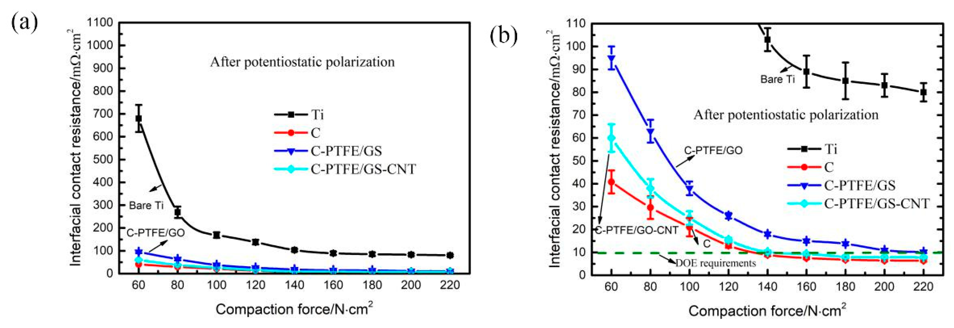
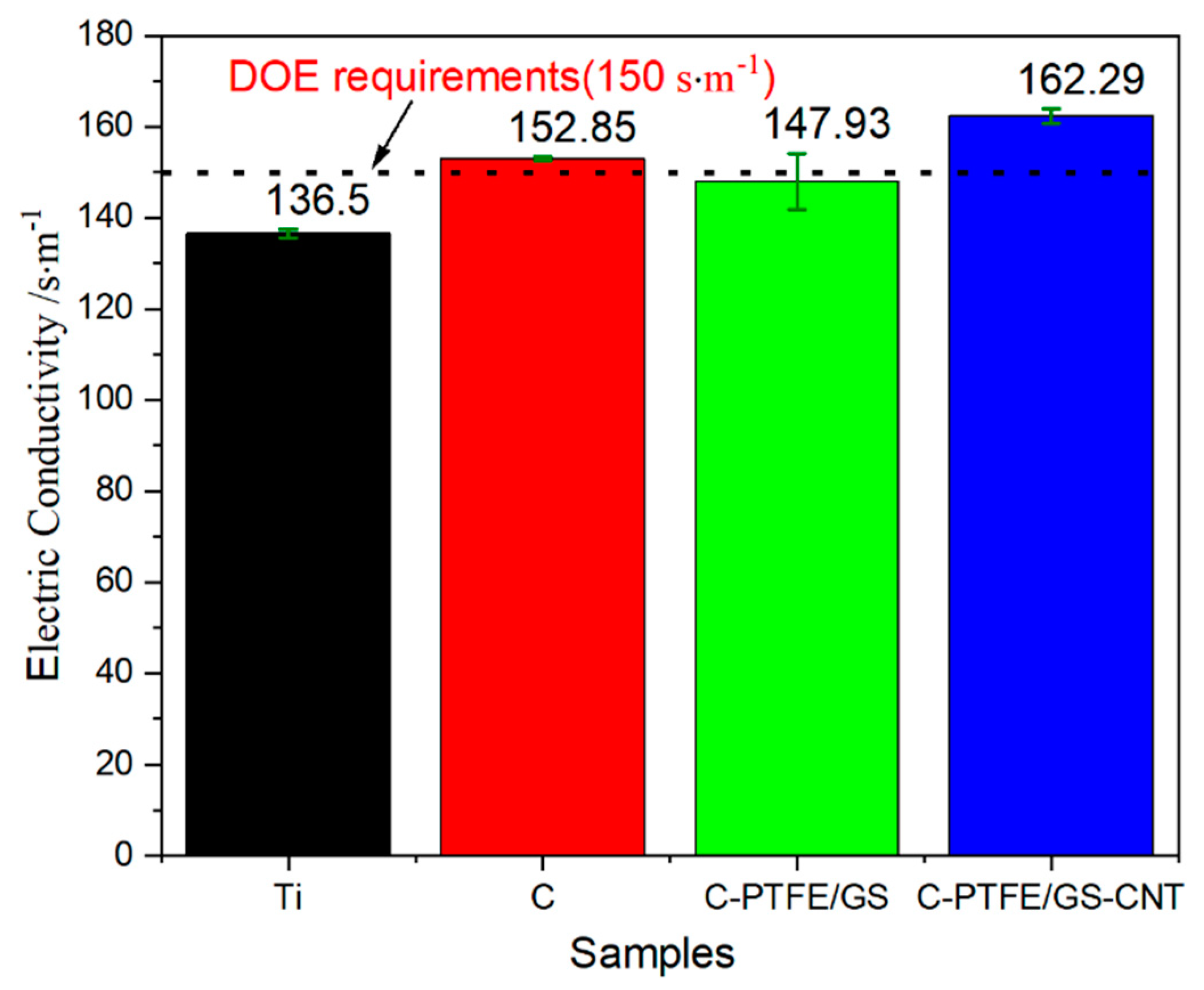
3.5. The Measurements of Conductivity

Figure 10 shows the surface–electric resistance of the bare Ti, carbon coating, C-PTFE/GS and C-PTFE/GS-CNT coating, respectively. After the potentiostatic test of bipolar plates, the surface conductivity was 136.5 S·cm−1. The conductivity of the carbon-coated sample was 152.85 S·cm−1. The conductivity of the carbon coating modified by graphite sheet and PTFE decreased to 147.93 S·cm−1 due to the presence of resin. The best conductivity of 162.29 S·cm−1 was obtained from composite coating, including CNT.
It is clearly indicated that the ICR decreases with the increase in applied force in the four samples due to the increase in the contacting area in Figure 11a. At the force of 60 N·cm−2, the ICR value of bare Ti, carbon, C-PTFE/GS and C-PTFE/GS-CNT coating is 680, 40.8, 95 and 60 mΩ·cm2, respectively. ICR value of the bare Ti sample is very high, which is attributed to the formation of TiO2 on the surface of the Ti after a potentiostatic test. At the loading force of 140 N·cm2, the ICR value of bare Ti, carbon, C-PTFE/GS and C-PTFE/GS-CNT coating is 103, 8.9, 18, 10.1 mΩ·cm2, respectively. The ICR value of C-PTFE/GS and C-PTFE/GS-CNT coating is 15 mΩ·cm2 and 9.3 N/cm2 at the force of 160 N/cm2, respectively. The conductivity of the Ti bipolar plates was improved by carbon composite coatings on the surface of the Ti. The ICR of a composite carbon-coated sample shows a lower value compared with bare Ti. The ICR increases with the addition of PTFE, which has poor electrical conductivity. The conductivity of C-PTFE/GS modified by CNT was greatly improved. The ICR of C-PTFE/GS-CNT was close to that of pure carbon coating when the applied force exceeded 120 N/cm2. Therefore, the ICR value of C-PTFE/GS coating coincides with the requirement of DOE’s targets (ICR < 10 mΩ·cm2).

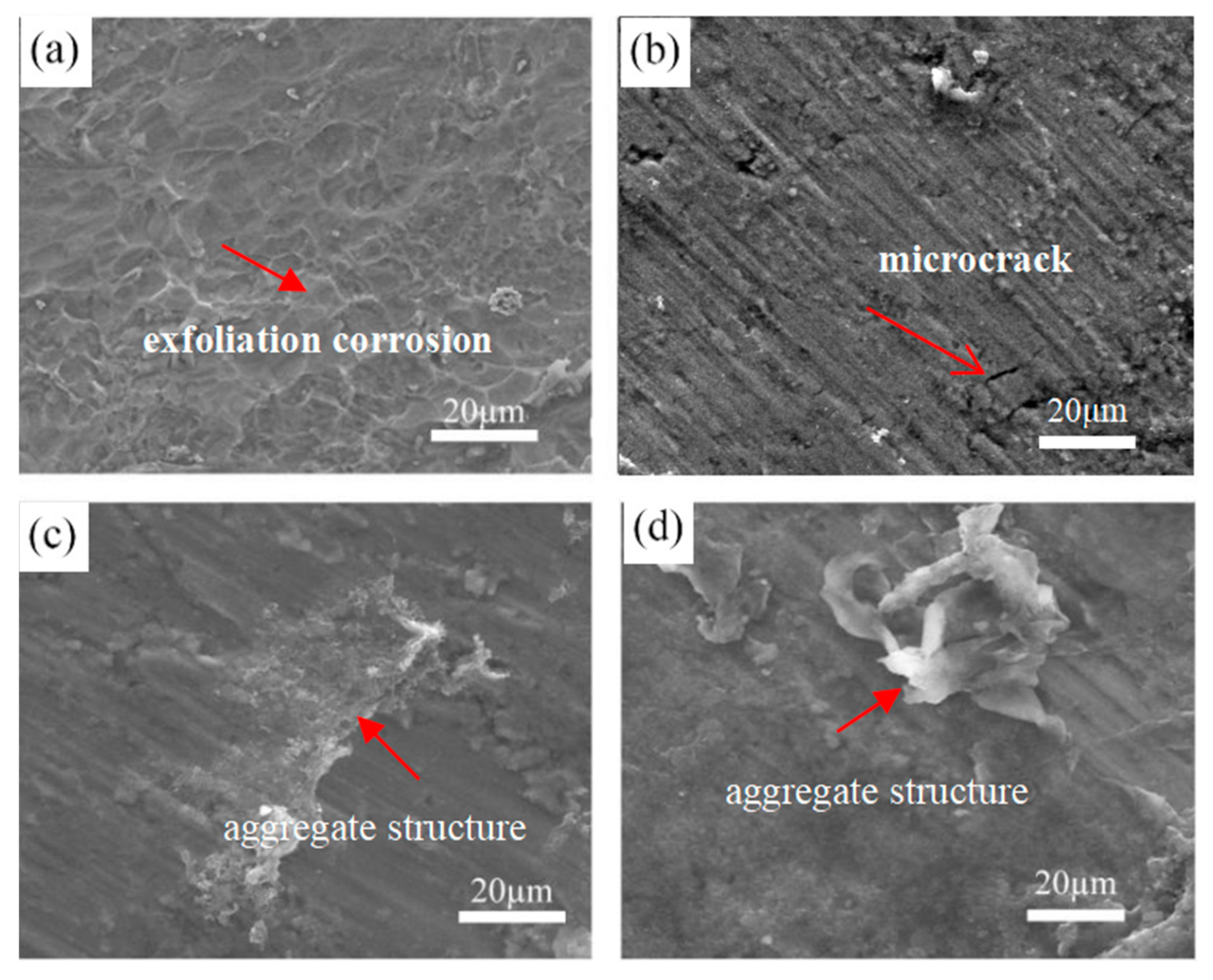
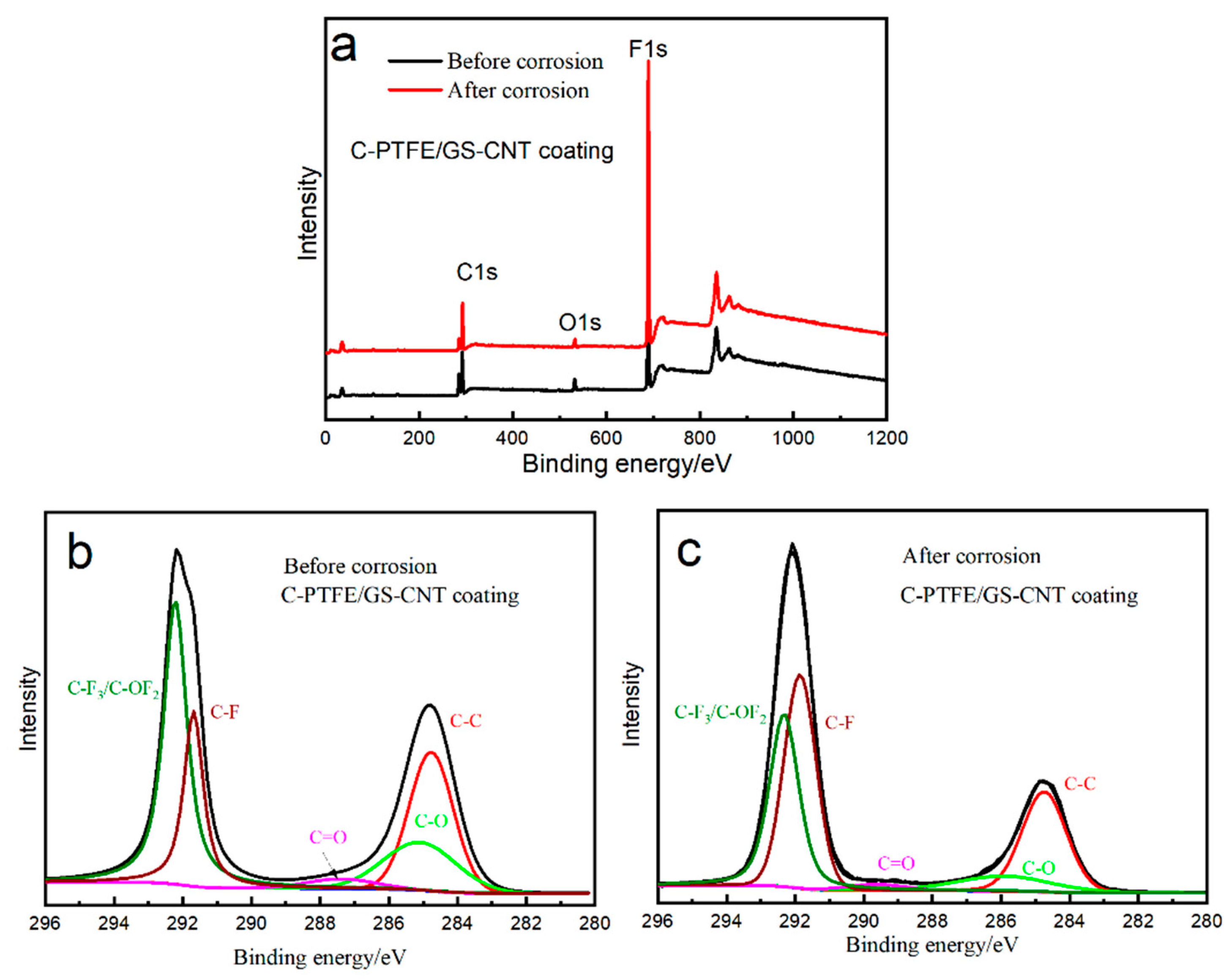
3.6. Corrosive Morphology after Potentiostatic Polarization

Figure 12 shows the surface morphology of the coating after potentiostatic polarization testing in the simulated environment of PEMFCs for 5 h with bubbling O2 at 0.6 V under 70 °C. In Figure 12a, the corrosive pits appear on the substrate with severe corrosion. Figure 12b shows the carbon coating after potentiostatic polarization. No defects such as cracks were observed in the coating. Few micropores appear on the corrosive surface. In contrast, the relatively complete surface appears on the C-PTFE/GS and C-PTFE/GS-CNT coating in Figure 12c,d, respectively. There are no peel offs from the surface of the coating due to corrosion. The existing aggregates are still embedded on the surface of the coating, which indicates the better corrosion resistance compared with the bare Ti and the carbon coating on Ti. This is no obvious change in surface morphology between the C-PTFE/GS and C-PTFE/GS-CNT coating after corrosion. Therefore, the addition of PTFE in the coating is favored for enhancing the corrosion resistance. The addition of CNT is helpful to enhance the conductivity of the coating without changing the corrosion resistance.

4. Conclusions

It can be concluded that the addition of PTFE to the coating is helpful to improve corrosion resistance. The addition of CNT is helpful to enhance the electrical conductivity of surface and interfacial contacting resistance in simulated environments of PEMFCs. There are good hydrophobic properties of the C-PTFE/GS and C-PTFE/GS-CNT composite coating, which reduce the contacting area between the corrosive solution and coating on Ti to enhance the corrosion resistance of bipolar plates. Hence, the Ti plate with composite coating C-PTFE/GS will be a great potential application as bipolar plates of PEMFCs.

Author Contributions

C.O.: Conceptualization, methodology, formal analysis and investigation, writing draft text; D.X.: Discussion and methodology. All authors have read and agreed to the published version of the manuscript.

Funding

This research was funded by the Natural Science Foundation of Jiangsu Province, Grant No. BK20190973.

Institutional Review Board Statement

Not applicable.

Informed Consent Statement

Not applicable.

Data Availability Statement

Not applicable.

Conflicts of Interest

The authors declare no conflict of interest.

References

  1. Ouyang, C.; Xun, D.; Jian, G. N-doped and sulfonated reduced graphene oxide supported PtNi nanoparticles as highly efficient electrocatalysts for oxygen reduction reaction. Coatings 2022, 12, 1049. [Google Scholar] [CrossRef]
  2. Sinniah, J.D.; Wong, W.Y.; Loh, K.S.; Yunus, R.M.; Timmiati, S.N. Perspectives on carbon-alternative materials as Pt catalyst supports for a durable oxygen reduction reaction in proton exchange membrane fuel cells. J. Power Sources 2022, 534, 231422. [Google Scholar] [CrossRef]
  3. Barnoon, P.; Toghraie, D.; Mehmandoust, B.; Fazilati, M.A.; Eftekhari, S.A. Natural-forced cooling and Monte-Carlo multi-objective optimization of mechanical and thermal characteristics of a bipolar plate for use in a proton exchange membrane fuel cell. Energy Rep. 2022, 8, 2747–2761. [Google Scholar] [CrossRef]
  4. Chen, G.; Singh, S.K.; Takeyasu, K.; Hill, J.P.; Nakamura, J.; Ariga, K. Versatile nanoarchitectonics of Pt with morphology control of oxygen reduction reaction catalysts. Sci. Technol. Adv. Mater. 2022, 23, 413–423. [Google Scholar] [CrossRef]
  5. Park, Y.; Shin, K.; Lee, C.; Lee, S.-Y.; Lee, Y.-K.; Kim, C.-H.; Cho, H.-S.; Henkelman, G.; Lee, H.M. Iterative redox activation promotes interfacial synergy in an Ag/CuxO catalyst for oxygen reduction. Chem. Eng. J. 2022, 446, 136966. [Google Scholar] [CrossRef]
  6. Fortunato, G.V.; Cardoso, E.S.F.; Martini, B.K.; Maia, G. Ti/Pt−Pd-based nanocomposite: Effects of metal oxides on the oxygen reduction reaction. ChemElectroChem 2020, 7, 1610–1618. [Google Scholar] [CrossRef]
  7. Ouyang, C.; Zhang, X.; Wu, M.; Xun, D.; Gao, P. Physical and electrochemical properties of Ni-P/TiN coated Ti for bipolar plates in PEMFCs. Int. J. Electrochem. Sci. 2020, 15, 80–93. [Google Scholar] [CrossRef]
  8. Yang, L.; Chen, M.; Wang, J.; Qiao, Y.; Guo, P.; Zhu, S.; Wang, F. Microstructure and composition evolution of a single-crystal superalloy caused by elements interdiffusion with an overlay NiCrAlY coating on oxidation. J. Mater. Sci. Technol. 2020, 45, 49–58. [Google Scholar] [CrossRef]
  9. Wang, L.; Northwood, D.; Nie, X.; Housden, J.; Spain, E.; Leyland, A.; Matthews, A. Corrosion properties and contact resistance of TiN, TiAlN and CrN coatings in simulated proton exchange membrane fuel cell environments. J. Power Sources 2010, 195, 3814–3821. [Google Scholar] [CrossRef]
  10. Wang, H.-C.; Hou, K.-H.; Lu, C.-E.; Ger, M.-D. The study of electroplating trivalent CrC alloy coatings with different current densities on stainless steel 304 as bipolar plate of proton exchange membrane fuel cells. Thin Solid Film. 2014, 570, 209–214. [Google Scholar] [CrossRef]
  11. Zhang, H.; Lin, G.; Hou, M.; Hu, L.; Han, Z.; Fu, Y.; Shao, Z.; Yi, B. CrN/Cr multilayer coating on 316L stainless steel as bipolar plates for proton exchange membrane fuel cells. J. Power Sources 2012, 198, 176–181. [Google Scholar] [CrossRef]
  12. Yi, P.; Peng, L.; Zhou, T.; Wu, H.; Lai, X. Development and characterization of multilayered Cr–C/a-C:Cr film on 316L stainless steel as bipolar plates for proton exchange membrane fuel cells. J. Power Sources 2013, 230, 25–31. [Google Scholar] [CrossRef]
  13. Yi, P.; Peng, L.; Zhou, T.; Huang, J.; Lai, X. Composition optimization of multilayered chromium-nitride–carbon film on 316L stainless steel as bipolar plates for proton exchange membrane fuel cells. J. Power Sources 2013, 236, 47–53. [Google Scholar] [CrossRef]
  14. Feng, K.; Li, Z.; Lu, F.; Huang, J.; Cai, X.; Wu, Y. Corrosion resistance and electrical properties of carbon/chromium–titanium–nitride multilayer coatings on stainless steel. J. Power Sources 2014, 249, 299–305. [Google Scholar] [CrossRef]
  15. Zada, A.; Ali, N.; Subhan, F.; Anwar, N.; Ali Shah, M.I.; Ateeq, M.; Hussain, Z.; Zaman, K.; Khan, M. Suitable energy platform significantly improves charge separation of g-C3N4 for CO2 reduction and pollutant oxidation under visible-light. Prog. Nat. Sci. 2019, 29, 138–144. [Google Scholar] [CrossRef]
  16. Gao, P.; Xie, Z.; Wu, X.; Ouyang, C.; Lei, T.; Yang, P.; Liu, C.; Wang, J.; Ouyang, T.; Huang, Q. Development of Ti bipolar plates with carbon/PTFE/TiN composites coating for PEMFCs. Int. J. Hydrog. Energy 2018, 43, 20947–20958. [Google Scholar] [CrossRef]
  17. Wang, W.-L.; He, S.-M.; Lan, C.-H. Protective graphite coating on metallic bipolar plates for PEMFC applications. Electrochim. Acta 2012, 62, 30–35. [Google Scholar] [CrossRef]
  18. Larijani, M.; Yari, M.; Afshar, A.; Jafarian, M.; Eshghabadi, M. A comparison of carbon coated and uncoated 316L stainless steel for using as bipolar plates in PEMFCs. J. Alloys Compd. 2011, 509, 7400–7404. [Google Scholar] [CrossRef]
  19. Li, W.; Liu, L.-T.; Li, Z.-X.; Wang, Y.-F.; Li, H.-Z.; Lei, J.-J. Corrosion resistance and conductivity of amorphous carbon coated SS316L and TA2 bipolar plates in proton-exchange membrane fuel cells. Diam. Relat. Mater. 2021, 118, 108503. [Google Scholar] [CrossRef]
  20. Bi, F.; Peng, L.; Yi, P.; Lai, X. Multilayered Zr–C/a-C film on stainless steel 316L as bipolar plates for proton exchange membrane fuel cells. J. Power Sources 2016, 314, 58–65. [Google Scholar] [CrossRef]
  21. Lin, M.-T.; Wan, C.-H.; Wu, W. Comparison of corrosion behaviors between SS304 and Ti substrate coated with (Ti,Zr)N thin films as Metal bipolar plate for unitized regenerative fuel cell. Thin Solid Films 2013, 544, 162–169. [Google Scholar] [CrossRef]
  22. Pingping, G.; Chun, O.; Zhiyong, X.; Tao, T. Corrosion protection of electroless plating Ni-P including tin nanoparticles for bipolar plates of PEMFCs. Surf. Rev. Lett. 2018, 25, 1850052. [Google Scholar] [CrossRef]
  23. Gao, M.L.; Wu, X.B.; Gao, P.P.; Ting, L.E.I.; Liu, C.X.; Xie, Z.Y. Properties of hydrophobic carbon–PTFE composite coating with high corrosion resistance by facile preparation on pure Ti. Trans. Nonferrous Met. Soc. China 2019, 29, 2321–2330. [Google Scholar] [CrossRef]
  24. Zhou, H.; Gao, P.; Wang, P.; Xie, Z.; Wu, X. Titanium nitride (TiN)–polytetrafluoroethylene (PTFE)-modified carbon paper used in PEM fuel cells: Characterization and corrosion-resistant mechanism. Appl. Phys. A 2019, 126, 37. [Google Scholar] [CrossRef]
  25. Liu, R.; Jia, Q.; Zhang, B.; Lai, Z.; Chen, L. Protective coatings for metal bipolar plates of fuel cells: A review. Int. J. Hydrog. Energy 2022, 47, 22915–22937. [Google Scholar] [CrossRef]
  26. Tokutake, K.; Nishi, H.; Ito, D.; Okazaki, S.; Serizawa, Y. Relationship between degradation characteristics of organic coating on internal bottom plate of oil storage tank and constant-phase element parameter values. Prog. Org. Coatings 2015, 87, 69–74. [Google Scholar] [CrossRef]
  27. Yin, Y.; Yang, Y.; Liu, G.; Chen, H.; Gong, D.; Ying, Y.; Fan, J.; Liu, S.; Li, Z.; Wang, C.; et al. Ultrafast solid-phase synthesis of 2D pyrene-alkadiyne frameworks towards efficient capture of radioactive iodine. Chem. Eng. J. 2022, 441, 135996. [Google Scholar] [CrossRef]
  28. Dang, A.; Sun, Y.; Fang, C.; Li, T.; Liu, X.; Xia, Y.; Ye, F.; Zada, A.; Khan, M. Rational design of Ti3C2/carbon nanotubes/MnCo2S4 electrodes for symmetric supercapacitors with high energy storage. Appl. Surf. Sci. 2022, 581, 152432. [Google Scholar] [CrossRef]
  29. Dang, A.; Sun, Y.; Liu, Y.; Xia, Y.; Liu, X.; Gao, Y.; Wu, S.; Li, T.; Zada, A.; Ye, F. Flexible Ti3C2Tx/carbon nanotubes/CuS film electrodes based on a dual-structural design for high-performance all-solid-state supercapacitors. ACS Appl. Energy Mater. 2022, 5, 9158–9172. [Google Scholar] [CrossRef]
Figure 1. Illustration of preparation of composite coating on Ti substrate by the method of impregnation and hydrothermal.
Coatings 12 01649 g001
Figure 2. Principle of four-probe resistance test on coating layer and interface contact resistance, (a) schematic diagram of four-probe resistance test; (b) schematic diagram of interface contact resistance test (ICR).
Coatings 12 01649 g002
Figure 3. SEM images of the surface morphology (a) Ti upon immersing in 8 mol/L NaOH solution (b) Graphite sheets prepared by mechanical stripping; (c) Graphite sheets mixed with carbon nanotubes; (d) carbon coating prepared in 0.1 mol/L glucose solution; (e) composite coating of carbon, graphite and PTFE; (f) composite coating of carbon and graphite sheet mixed with carbon nanotubes and PTFE.
Coatings 12 01649 g003
Figure 4. TEM and HRTEM images of the surface morphology (a,b) TEM and HRTEM of graphite sheets mixed with carbon nanotubes; (ce) composite coating of carbon, graphite sheet and PTFE; (fh) composite coating of carbon, graphite mixed with carbon nanotubes and PTFE.
Coatings 12 01649 g004
Figure 5. Potentiodynamic polarization curves of bare Ti, carbon film-coated Ti, C-PTFE/GO film-coated Ti and C-PTFE/GO-CNT film-coated Ti 70 °C, 0.5 M H2SO4, 2 ppm HF, air bubbling) conditions.
Coatings 12 01649 g005
Figure 6. Potentiostatic polarization curves of bare Ti (black), carbon coating, C-PTFE/GS coating and C-PTFE/GS-CNT coating under cathodic (0.6 V vs. SCE, 70 °C, 0.5 M H2SO4 + 2 ppm HF, air bubbling) conditions. (a) potentiostatic polarization curves; (b) enlarge potentiostatic polarization curves.
Coatings 12 01649 g006
Figure 7. EIS curves of bare Ti, carbon and carbon−PTFE, carbon-PTFE/GO and carbon-PTFE/GO-CNT composite films. (a) Nyquist plots; (b) Bode plots; (c) Rct value; (d) Equivalent circuits.
Coatings 12 01649 g007
Figure 8. Survey spectra of coatings: (a) XPS analysis of C-PTFE/GS-CNT films before and after corrosion; (b) C1s spectra of C-PTFE/GS-CNT films before corrosion; (c) C1s spectra of C-PTFE/GS-CNT films after corrosion.
Coatings 12 01649 g008
Figure 9. Contact angle of composite coatings after potentiostatic polarization (a) bare Ti; (b) carbon coating; (c) carbon-PTFE/GS coating; (d) carbon-PTFE/GS-CNT coating.
Coatings 12 01649 g009
Figure 10. The conductivity of different coatings was compared with DOE requirements.
Coatings 12 01649 g010
Figure 11. ICR of samples before potentiodynamic polarization with different compaction force in ambient environment. (a) ICR value; (b) Enlarged figure of the ICR value within 100 mΩ·cm2.
Coatings 12 01649 g011
Figure 12. Morphology of coating after testing of potentiostatic polarization in simulated environment of PEMFCs. (a) Bare Ti; (b) Carbon film; (c) C-PTFE/GS; (d) C-PTFE/GS-CNT.
Coatings 12 01649 g012
Table 1. The samples under different conditions of treatment.
Sample NumberSuspension Solution
TiBare Ti
CCarbon film
C-PTFE/GS1 wt.% PTFE + graphite sheet
C-PTFE/GS-CNT1 wt.% PTFE + graphite sheet/Carbon nanotubes
Table 2. Comparison of the corrosion current density under −0.1 V, 0.6 V and Polarization current and voltage.
SamplesAt −0.1 V
icorr.(μA/cm2)
At 0.6 V
icorr.(μA/cm2)
Polarization Voltage (V)Polarization icorr.(μA/cm2)
Ti1126−0.087.8
C6.30.890.10.06
C-PTFE/GS0.320.430.150.006
C-PTFE/GS-CNT0.080.050.280.014
Table 3. Fitting parameters and relative quantity analysis of compounds for C 1s spectra of C-PTFE/GS-CNT films before and after corrosion by XPS.
Chemical
Bonding
Binding
Energy/eV
Surface Composition/at.%
BeforeAfter
C–C284.625.44%23.39%
C–O286.414.31%8.04%
C=O288.92.74%1.81%
C–F291.637.96%35.61%
C–F3/C–OF2293.119.55%31.15%
Publisher’s Note: MDPI stays neutral with regard to jurisdictional claims in published maps and institutional affiliations.

