
Microstructure and Mechanical Properties of TiC/TiB Composite Ceramic Coatings In-Situ Synthesized by Ultrasonic Vibration-Assisted Laser Cladding


Abstract
:1. Introduction
2. Materials and Methods
2.1. Experimental Material Selection and Treatment
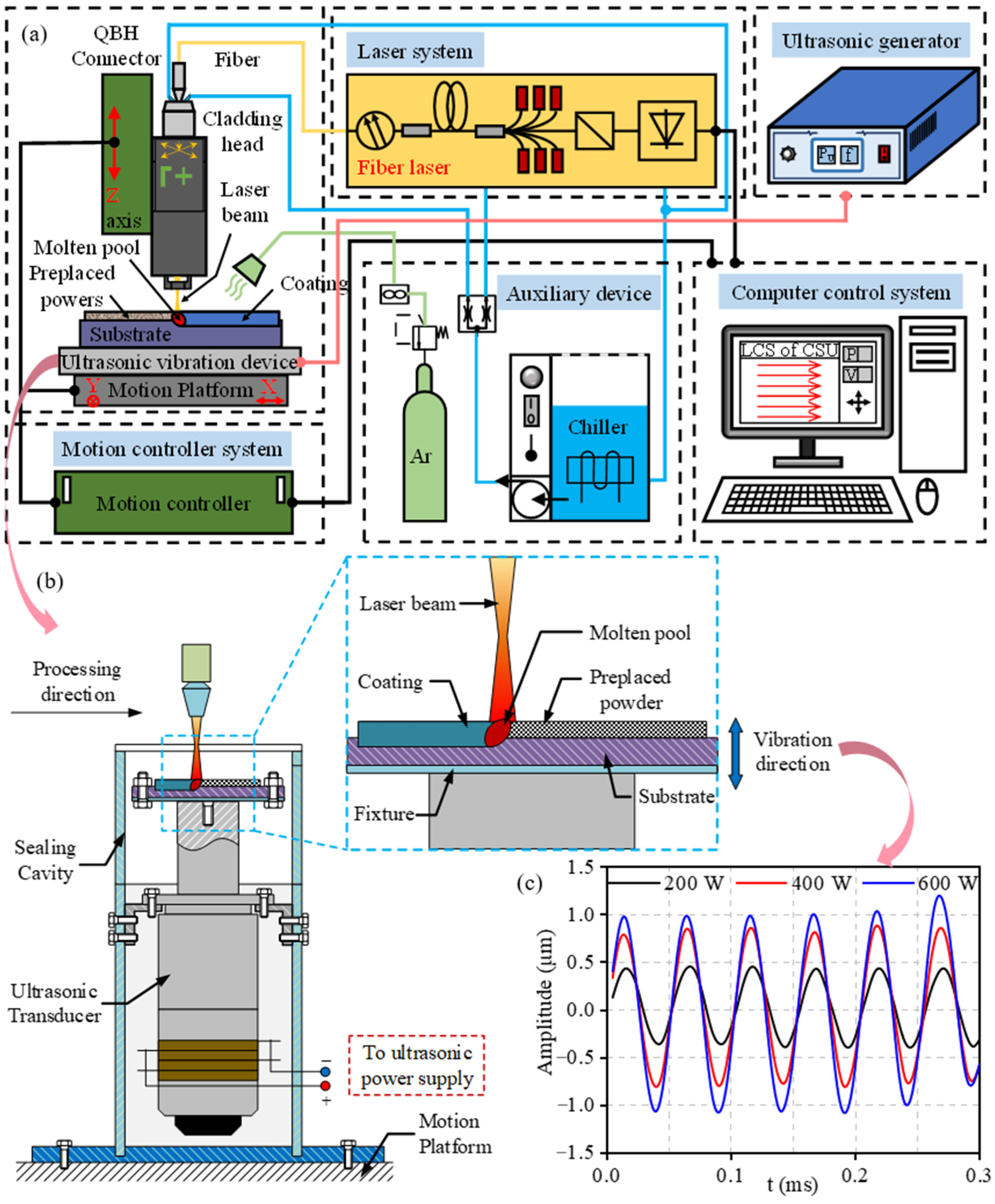
2.2. Ultrasonic Vibration-Assisted Laser Cladding Set-Up
2.3. Ultrasonic Vibration-Assisted Laser Cladding Process
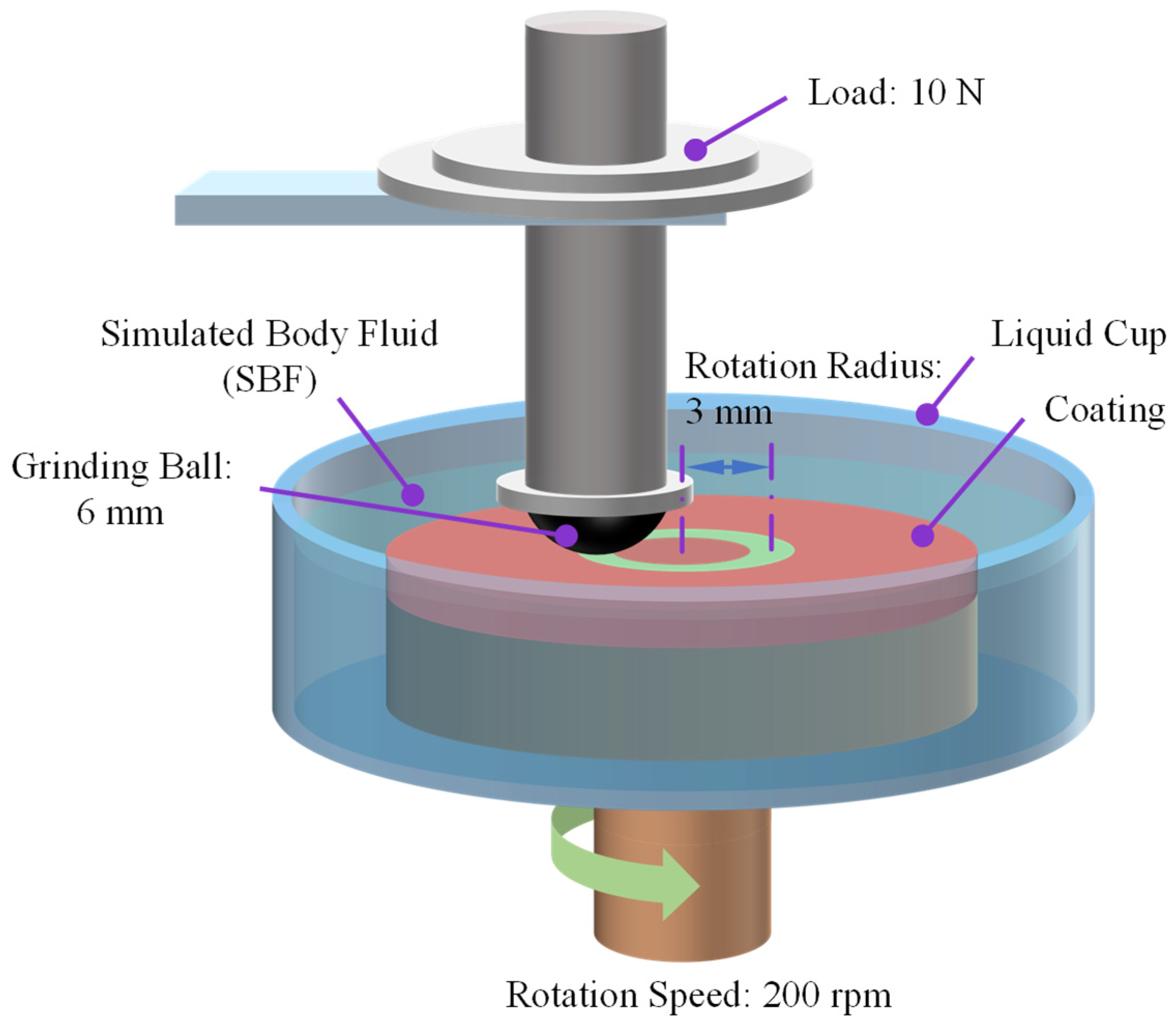
2.4. Coating Properties Test Methods
3. Results and Discussion
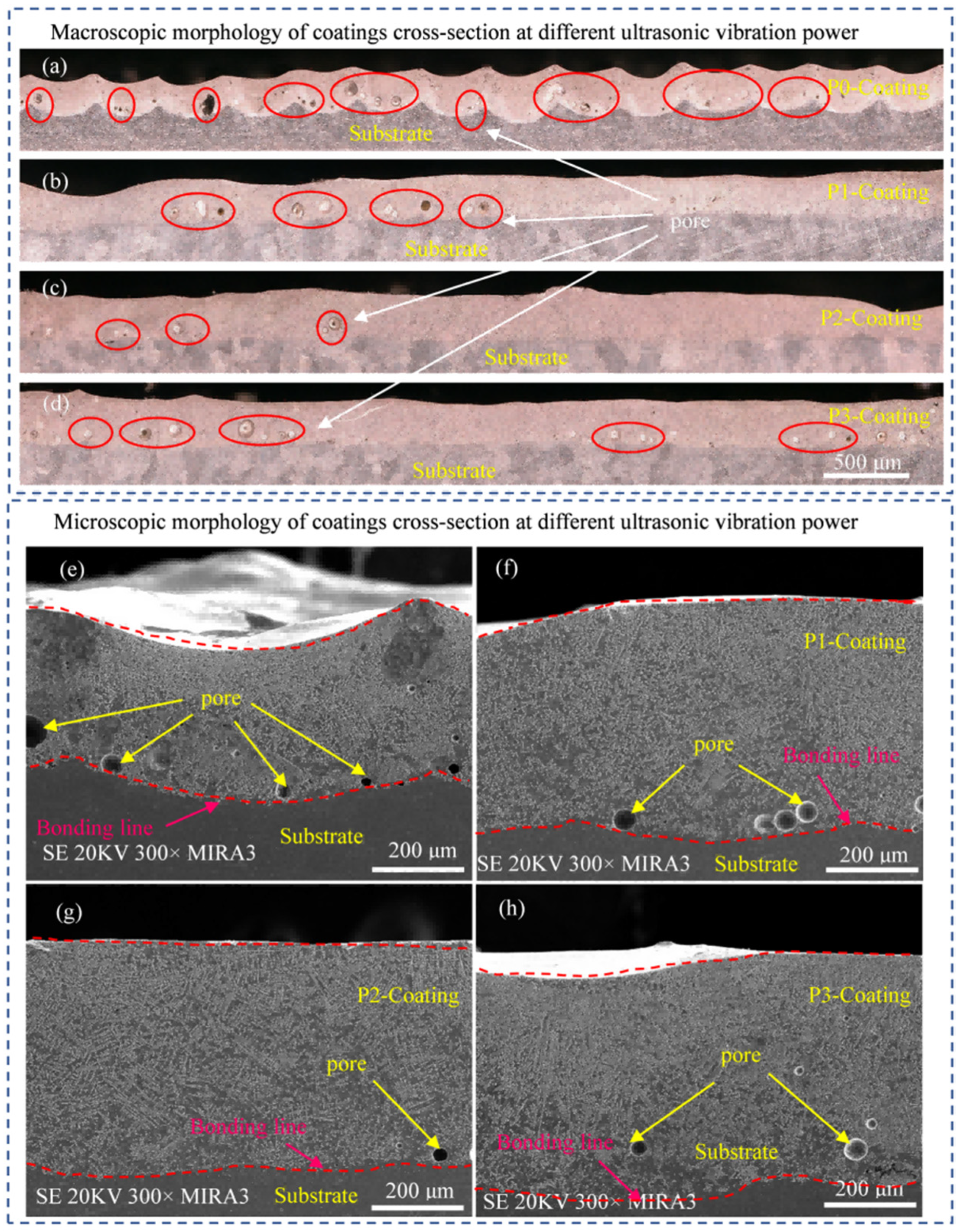
3.1. Effect of Ultrasonic Vibration on Morphology of Coating’s Cross-Section
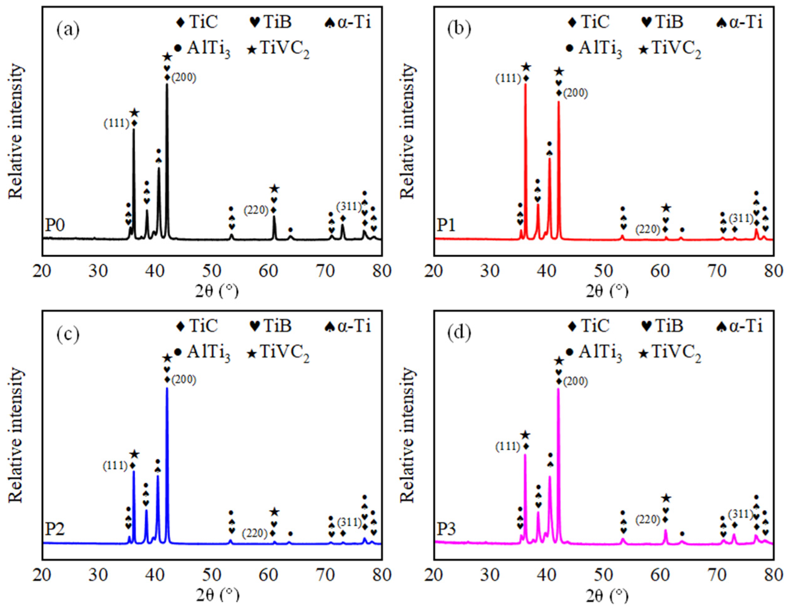
3.2. Effect of Ultrasonic Vibration on Phase Compositions of the Coatings
3.3. Effect of Ultrasonic Vibration on Microstructure of the Coatings
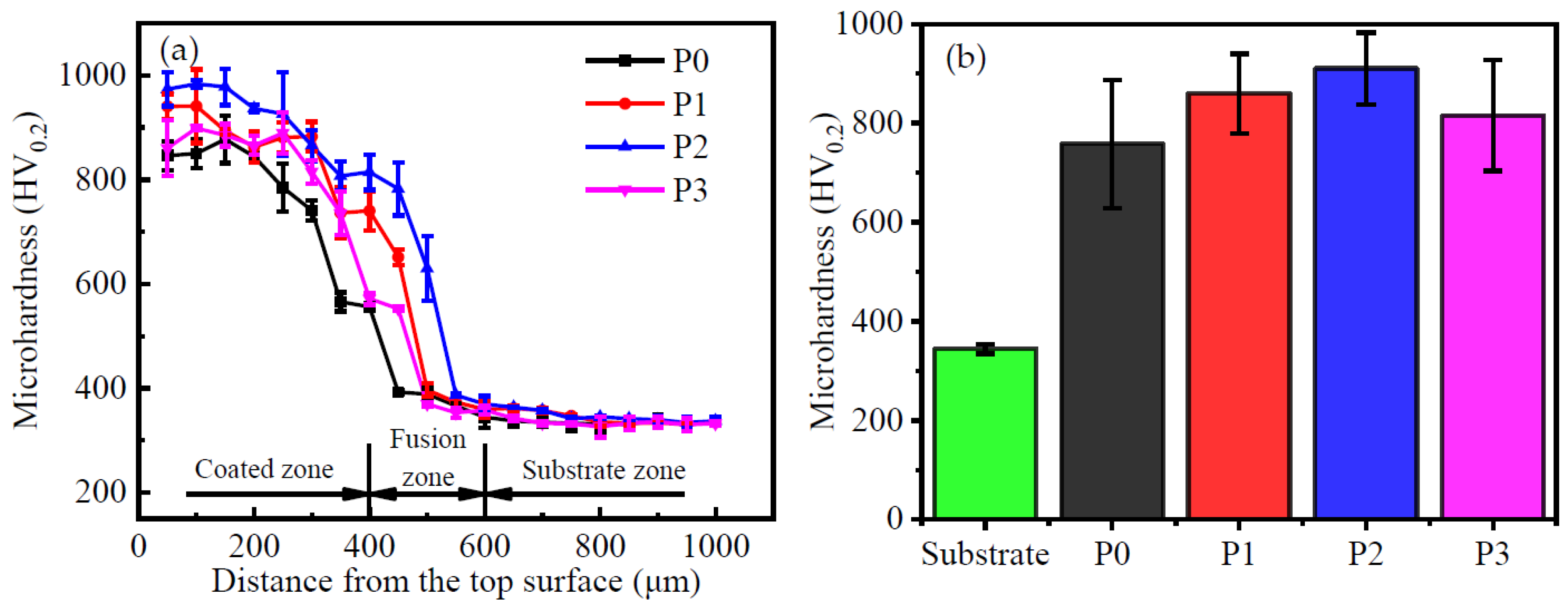
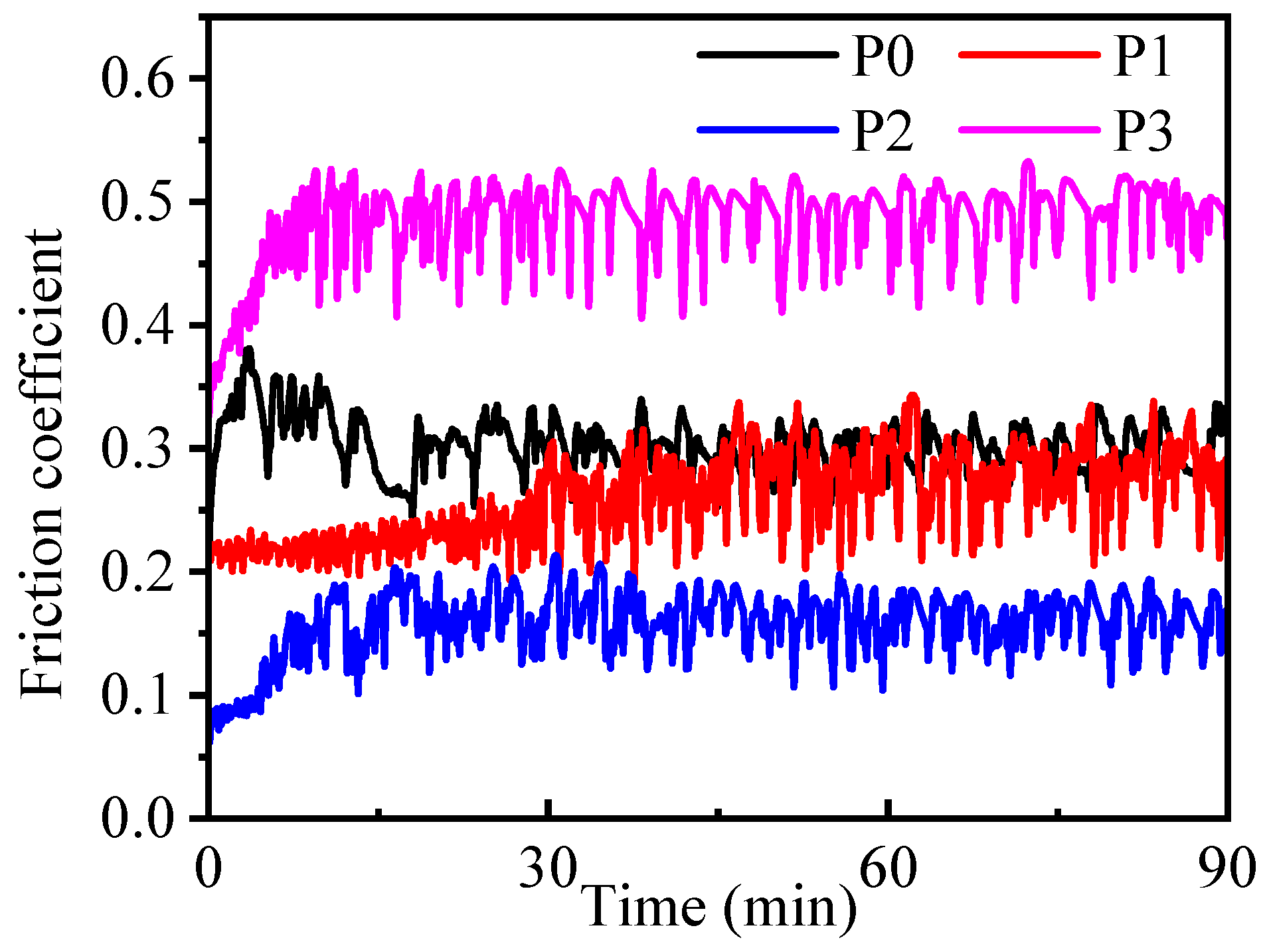
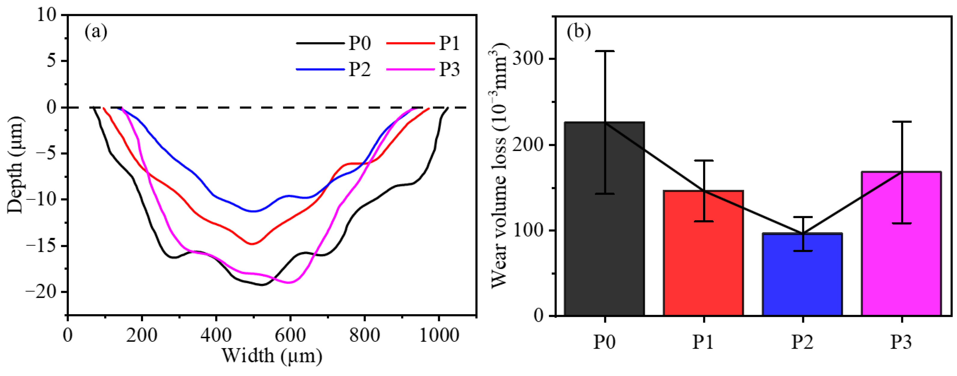
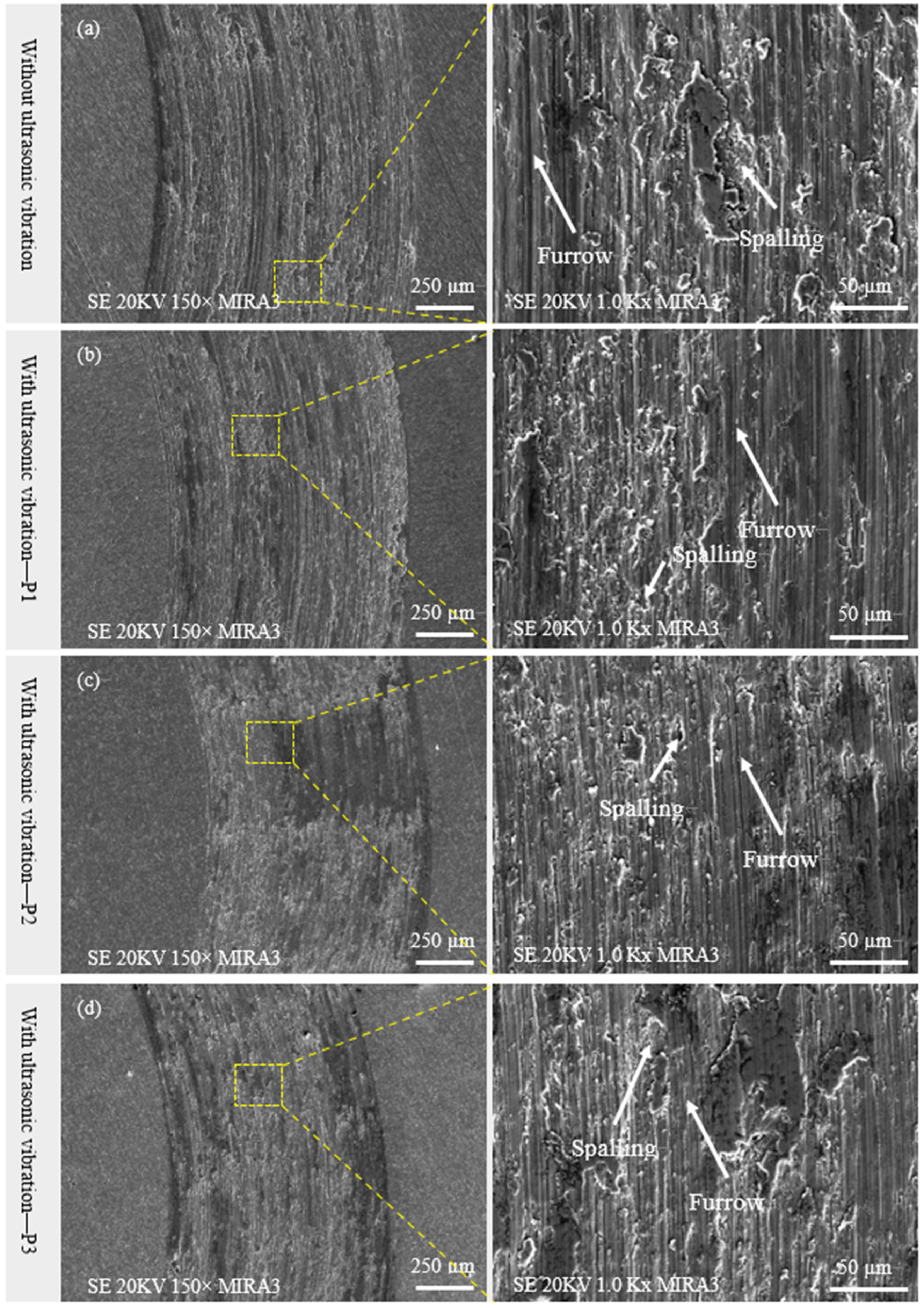
3.4. Effect of Ultrasonic Vibration on Micro-Hardness and Wear Resistance of the Coatings
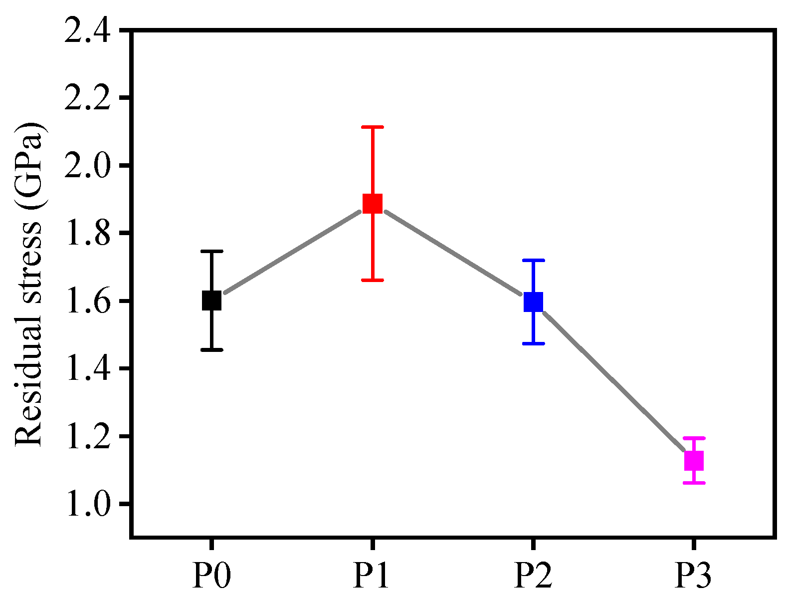
3.5. Effect of Ultrasonic Vibration on Residual Stress of the Coatings
4. Conclusions
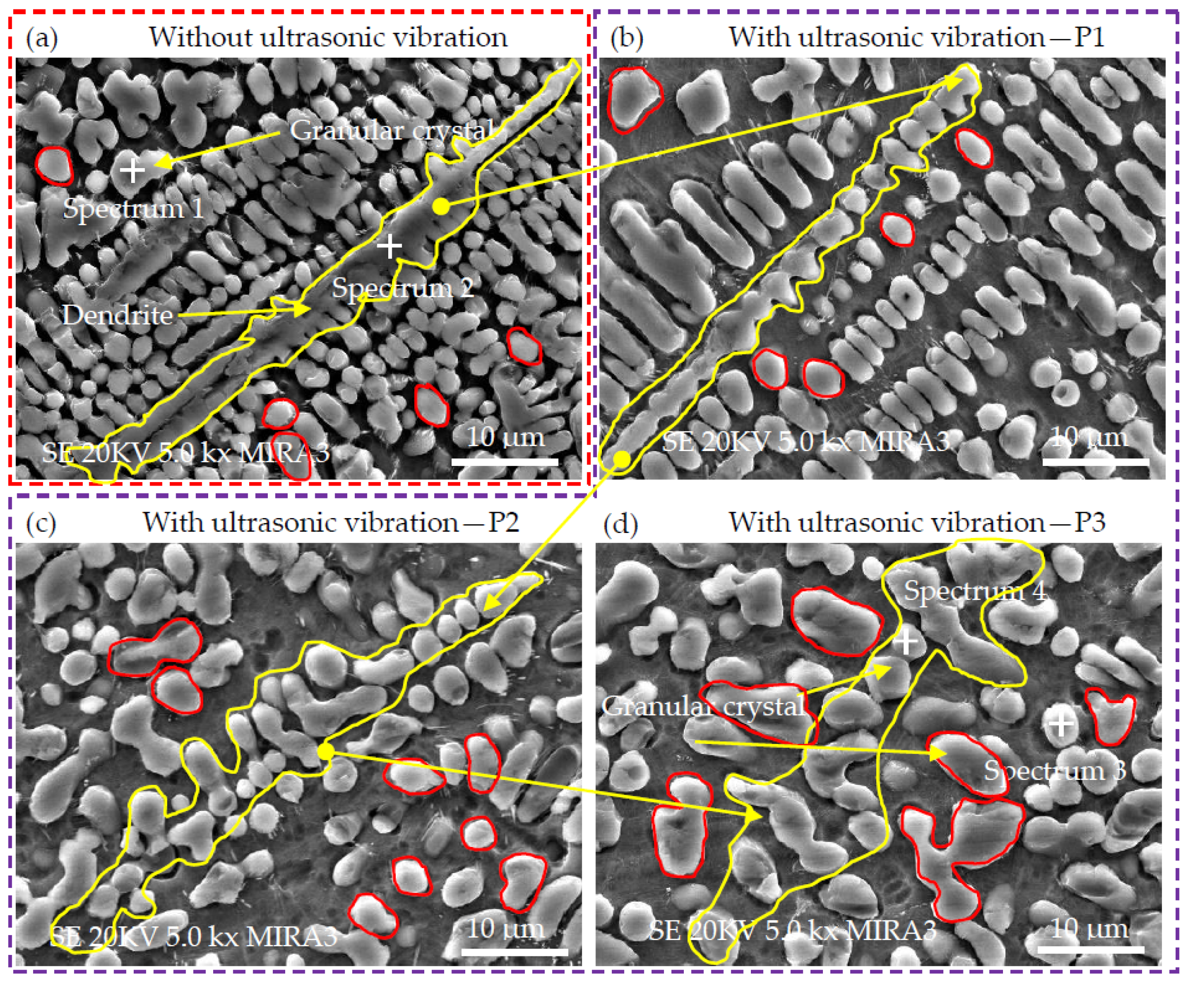
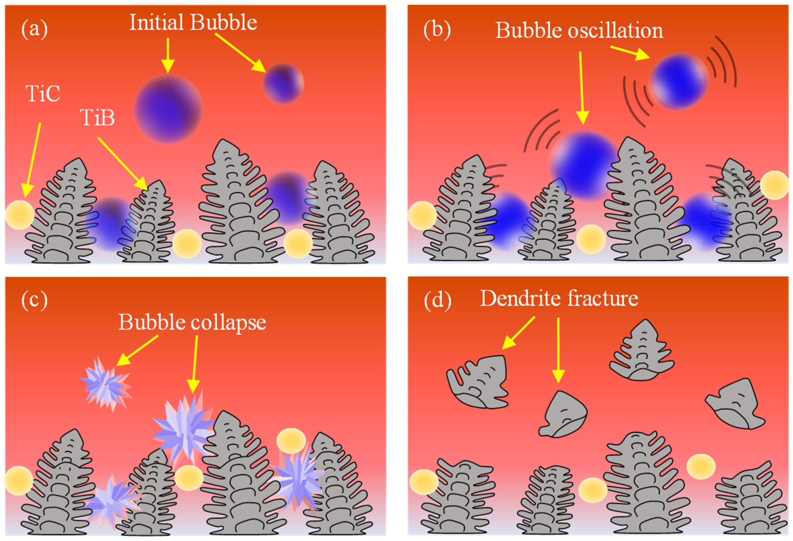
- The dendrites in the coating were broken by ultrasonic cavitation effect, and gradually turned into granular crystal grains with the increase of ultrasonic vibration power.
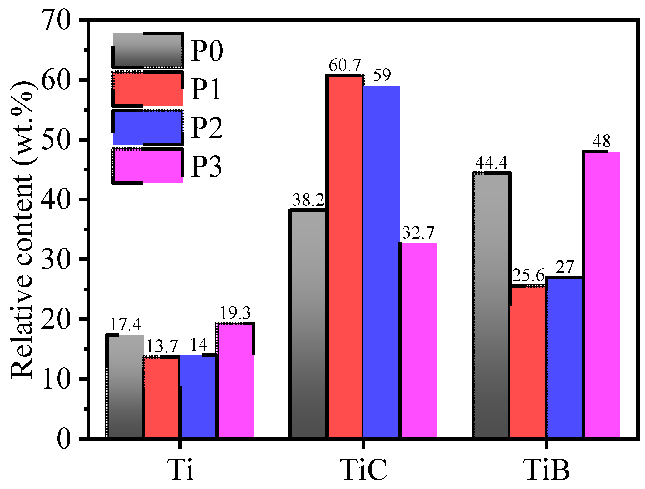
- The ultrasonic vibration introduced into the laser cladding process could increase the relative content of the ceramic phase (TiC, TiB) in the coating. The relative content of ceramic phases in the coating fabricated with ultrasonic vibration at power of 400 W was the highest at about 86.0 wt.%.
- The ultrasonic vibration introduced into the laser cladding process improved the tribological properties of the coating. The wear resistance of the coating fabricated with ultrasonic vibration power 400 W was about 1.2 times higher, and the friction coefficient was 50% lower than that of the coating fabricated without ultrasonic vibration.
Author Contributions
Funding
Institutional Review Board Statement
Informed Consent Statement
Data Availability Statement
Conflicts of Interest
References
- Kaur, M.; Singh, K. Review on titanium and titanium based alloys as biomaterials for orthopaedic applications. Mater. Sci. Eng. C 2019, 102, 844–862. [Google Scholar] [CrossRef] [PubMed]
- Ibrahim, M.Z.; Sarhan, A.A.; Yusuf, F.; Hamdi, M. Biomedical materials and techniques to improve the tribological, mechanical and biomedical properties of orthopedic implants—A review article. J. Alloys Compd. 2017, 714, 636–667. [Google Scholar] [CrossRef]
- Mahajan, A.; Devgan, S.; Sidhu, S.S. Surface alteration of biomedical alloys by electrical discharge treatment for enhancing the electrochemical corrosion, tribological and biological performances. Surf. Coat. Technol. 2021, 405, 126583. [Google Scholar] [CrossRef]
- Perumal, G.; Geetha, M.; Asokamani, R.; Alagumurthi, N. Wear studies on plasma sprayed Al2O3–40 wt% 8YSZ composite ceramic coating on Ti–6Al–4V alloy used for biomedical applications. Wear 2014, 311, 101–113. [Google Scholar] [CrossRef]
- Pham, D.Q.; Berndt, C.C.; Cizek, J.; Gbureck, U.; Zreiqat, H.; Lu, Z.; Ang, A.S.M. Baghdadite coating formed by hybrid water-stabilized plasma spray for bioceramic applications: Mechanical and biological evaluations. Mater. Sci. Eng. C 2021, 122, 111873. [Google Scholar] [CrossRef] [PubMed]
- Singh, H.; Kumar, R.; Prakash, C.; Singh, S. HA-based coating by plasma spray techniques on titanium alloy for orthopedic applications. Mater. Today Proc. 2021. [Google Scholar] [CrossRef]
- Salehi, S.; Kharaziha, M.; Salehi, M. Multifunctional plasma-sprayed nanocomposite coating based on FA-ZnO-GO with improved bioactivity and wear behaviour. Surf. Coat. Technol. 2020, 404, 126472. [Google Scholar] [CrossRef]
- Ibrahim, M.Z.; Sarhan, A.A.; Kuo, T.; Hamdi, M.; Yusof, F.; Chien, C.; Chang, C.; Lee, T. Advancement of the artificial amorphous-crystalline structure of laser cladded FeCrMoCB on nickel-free stainless-steel for bone-implants. Mater. Chem. Phys. 2019, 227, 358–367. [Google Scholar] [CrossRef]
- Guo, Y.; Li, X.; Liu, Q. A novel biomedical high-entropy alloy and its laser-clad coating designed by a cluster-plus-glue-atom model. Mater. Des. 2020, 196, 109085. [Google Scholar] [CrossRef]
- Ibrahim, M.Z.; Sarhan, A.A.; Kuo, T.; Yusof, F.; Hamdi, M.; Lee, T. Developing a new laser cladded FeCrMoCB metallic glass layer on nickel-free stainless-steel as a potential superior wear-resistant coating for joint replacement implants. Surf. Coat. Technol. 2020, 392, 125755. [Google Scholar] [CrossRef]
- Jing, Z.; Cao, Q.; Jun, H. Corrosion, wear and biocompatibility of hydroxyapatite bio-functionally graded coating on titanium alloy surface prepared by laser cladding. Ceram. Int. 2021, 47, 24641–24651. [Google Scholar] [CrossRef]
- Saeedi, R.; Razavi, R.S.; Bakhshi, S.R.; Erfanmanesh, M.; Bani, A.A. Optimization and characterization of laser cladding of NiCr and NiCr–TiC composite coatings on AISI 420 stainless steel. Ceram. Int. 2021, 47, 4097–4110. [Google Scholar] [CrossRef]
- Fan, P.; Zhang, G. Study on process optimization of WC-Co50 cermet composite coating by laser cladding. Int. J. Refract. Met. Hard Mater. 2020, 87, 105133. [Google Scholar] [CrossRef]
- Liu, H.; Liu, J.; Li, X.; Chen, P.; Yang, H.; Hao, J. Effect of heat treatment on phase stability and wear behavior of laser clad AlCoCrFeNiTi0.8 high-entropy alloy coatings. Surf. Coat. Technol. 2020, 392, 125758. [Google Scholar] [CrossRef]
- Chen, T.; Li, W.; Liu, D.; Xiong, Y.; Zhu, X. Effects of heat treatment on microstructure and mechanical properties of TiC/TiB composite bioinert ceramic coatings in-situ synthesized by laser cladding on Ti6Al4V. Ceram. Int. 2021, 47, 755–768. [Google Scholar] [CrossRef]
- Choi, J.; Choudhuri, S.K.; Mazumder, J. Role of preheating and specific energy input on the evolution of microstructure and wear properties of laser clad Fe-Cr-C-W alloys. J. Mater. Sci. 2000, 35, 3213–3219. [Google Scholar] [CrossRef]
- Hu, Y.; Ning, F.; Cong, W.; Li, Y.; Wang, X.; Wang, H. Ultrasonic vibration-assisted laser engineering net shaping of ZrO2-Al2O3 bulk parts: Effects on crack suppression, microstructure, and mechanical properties. Ceram. Int. 2018, 44, 2752–2760. [Google Scholar] [CrossRef]
- Ning, F.; Hu, Y.; Liu, Z.; Cong, W.; Li, Y.; Wang, X. Ultrasonic vibration-assisted laser engineered net shaping of Inconel 718 parts: A feasibility study. Procedia Manuf. 2017, 10, 771–778. [Google Scholar] [CrossRef]
- Wang, H.; Hu, Y.; Ning, F.; Cong, W. Ultrasonic vibration-assisted laser engineered net shaping of Inconel 718 parts: Effects of ultrasonic frequency on microstructural and mechanical properties. J. Mater. Process. Technol. 2020, 276, 116395. [Google Scholar] [CrossRef]
- Zhu, L.; Yang, Z.; Xin, B.; Wang, S.; Meng, G.; Ning, J.; Xue, P. Microstructure and mechanical properties of parts formed by ultrasonic vibration-assisted laser cladding of Inconel 718. Surf. Coat. Technol. 2021, 410, 126964. [Google Scholar] [CrossRef]
- Ma, G.; Yan, S.; Wu, D.; Miao, Q.; Liu, M.; Niu, F. Microstructure evolution and mechanical properties of ultrasonic assisted laser clad yttria stabilized zirconia coating. Ceram. Int. 2017, 43, 9622–9629. [Google Scholar] [CrossRef]
- Zhang, M.; Zhao, G.; Wang, X.; Liu, S.; Ying, W. Microstructure evolution and properties of in-situ ceramic particles reinforced Fe-based composite coating produced by ultrasonic vibration assisted laser cladding processing. Surf. Coat. Technol. 2020, 403, 126445. [Google Scholar] [CrossRef]
- Chen, T.; Liu, D.; Wu, F.; Wang, H. Effect of CeO2 on microstructure and wear resistance of TiC bioinert coatings on Ti6Al4V alloy by laser cladding. Materials 2018, 11, 58. [Google Scholar] [CrossRef] [PubMed] [Green Version]
- Poncet, C.; Ferrouillat, S.; Vignal, L.; Memponteil, A.; Bulliard-Sauret, O.; Gondrexon, N. Enhancement of heat transfer in forced convection by using dual low-high frequency ultrasound. Ultrason. Sonochem. 2021, 71, 105351. [Google Scholar] [CrossRef] [PubMed]
- Gao, J.; Li, C.; Chen, Z.; Han, X. Effect of ultrasonic vibration on the solidification behavior of laser cladding polycrystalline based on phase field method. Mater. Rep. 2021, 35, 12161–12168. [Google Scholar] [CrossRef]
- Han, X.; Li, C.; Yang, Y.; Gao, X.; Gao, H. Experimental research on the influence of ultrasonic vibrations on the laser cladding process of a disc laser. Surf. Coat. Technol. 2021, 406, 126750. [Google Scholar] [CrossRef]
- Ye, L.; Zhu, X.; Liu, Y. Numerical study on dual-frequency ultrasonic enhancing cavitation effect based on bubble dynamic evolution. Ultrason. Sonochem. 2019, 59, 104744. [Google Scholar] [CrossRef]
- Almeida, R.; Börret, R.; Rimkus, W.; Harrison, D.K.; DeSilva, A.K.M. Material removal simulation for steel mould polishing. Prod. Manuf. Res. 2017, 5, 235–249. [Google Scholar] [CrossRef] [Green Version]
- Morin, L.; Braham, C.; Tajdary, P.; Seddik, R.; Gonzalez, G. Reconstruction of heterogeneous surface residual-stresses in metallic materials from X-ray diffraction measurements. Mech. Mater. 2021, 158, 103882. [Google Scholar] [CrossRef]
- Oliver, W.C.; Pharr, G.M. Measurement of hardness and elastic modulus by instrumented indentation: Advances in understanding and refinements to methodology. J. Mater. Res. 2004, 19, 3–20. [Google Scholar] [CrossRef]
- Rossini, N.; Dassisti, M.; Benyounis, K.; Olabi, A.G. Methods of measuring residual stresses in components. Mater. Des. 2012, 35, 572–588. [Google Scholar] [CrossRef] [Green Version]
- Syed, A.K.; Ahmad, B.; Guo, H.; Machry, T.; Eatock, D.; Meyer, J.; Fitzpatrick, M.E.; Zhang, X. An experimental study of residual stress and direction-dependence of fatigue crack growth behaviour in as-built and stress-relieved selective-laser-melted Ti6Al4V. Mater. Sci. Eng. A 2019, 755, 246–257. [Google Scholar] [CrossRef]


| Sample Mark | Ultrasonic Vibration Parameters | Laser Cladding Process Parameters | |||
|---|---|---|---|---|---|
| Ultrasonic Power (W) | Frequency (kHz) | Laser Power (W) | Scanning Speed (mm/s) | Spot Diameter (mm) | |
| P0 | 0 | 20 | 450 | 3 | 1 |
| P1 | 200 | ||||
| P2 | 400 | ||||
| P3 | 600 | ||||
| Sample | Spectrum | Ti | C | B | Al | V | Ti/C | Ti/B |
|---|---|---|---|---|---|---|---|---|
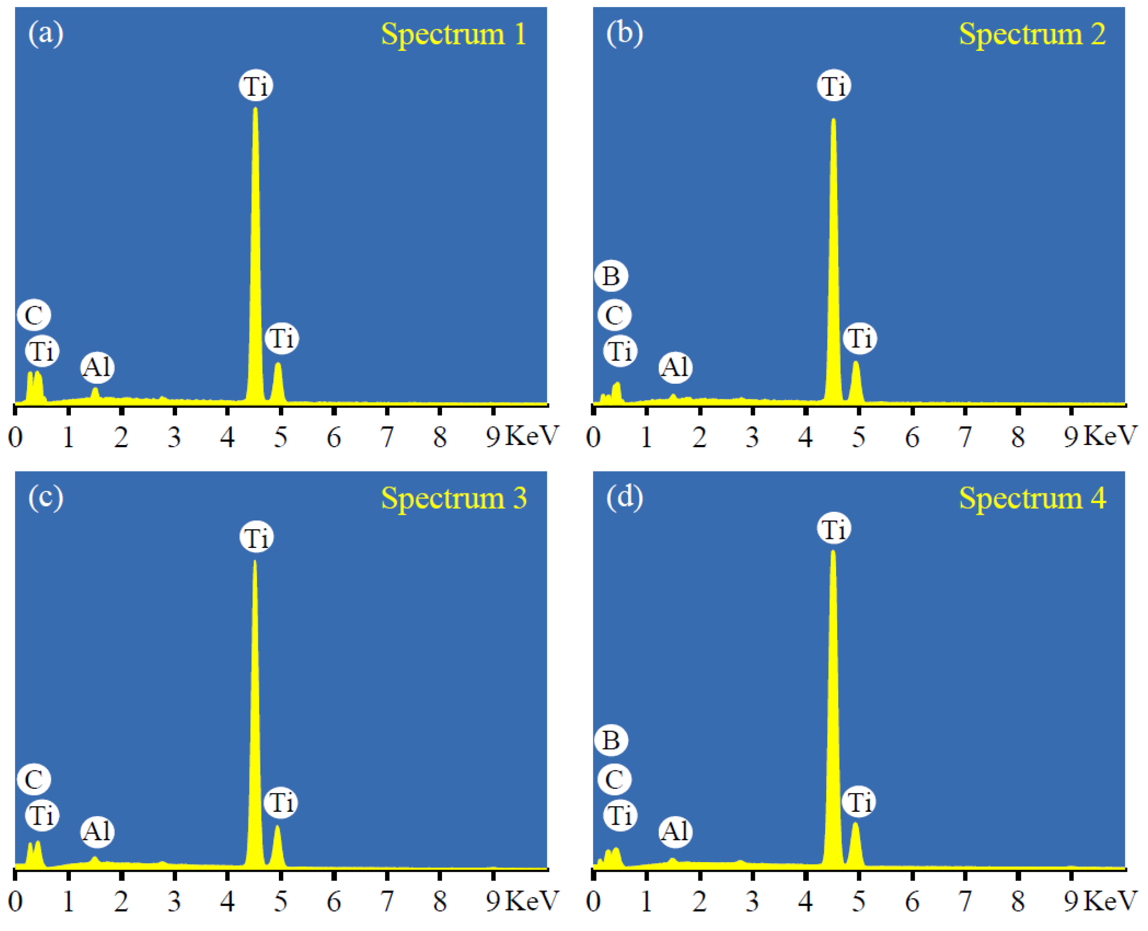
| P0-Coating | Spectrum 1 | 52.7 | 45.6 | - | 1.7 | - | 1.2 | - |
| Spectrum 2 | 36.2 | 18.6 | 44.8 | - | 0.4 | 1.9 | 0.8 | |
| P3-Coating | Spectrum 3 | 55.6 | 43.4 | - | 1.1 | - | 1.3 | - |
| Spectrum 4 | 34.2 | 26.9 | 38.2 | - | 0.5 | 1.3 | 0.9 |
| Sample | P0 | P1 | P2 | P3 |
|---|---|---|---|---|
| Elastic modulus (GPa) | 225 | 243 | 231 | 230 |
Publisher’s Note: MDPI stays neutral with regard to jurisdictional claims in published maps and institutional affiliations. |
© 2022 by the authors. Licensee MDPI, Basel, Switzerland. This article is an open access article distributed under the terms and conditions of the Creative Commons Attribution (CC BY) license (https://creativecommons.org/licenses/by/4.0/).
Share and Cite
Mi, H.; Chen, T.; Deng, Z.; Li, S.; Liu, J.; Liu, D. Microstructure and Mechanical Properties of TiC/TiB Composite Ceramic Coatings In-Situ Synthesized by Ultrasonic Vibration-Assisted Laser Cladding. Coatings 2022, 12, 99. https://doi.org/10.3390/coatings12010099
Mi H, Chen T, Deng Z, Li S, Liu J, Liu D. Microstructure and Mechanical Properties of TiC/TiB Composite Ceramic Coatings In-Situ Synthesized by Ultrasonic Vibration-Assisted Laser Cladding. Coatings. 2022; 12(1):99. https://doi.org/10.3390/coatings12010099
Chicago/Turabian StyleMi, Hangbiao, Tao Chen, Zixin Deng, Shengchen Li, Jian Liu, and Defu Liu. 2022. "Microstructure and Mechanical Properties of TiC/TiB Composite Ceramic Coatings In-Situ Synthesized by Ultrasonic Vibration-Assisted Laser Cladding" Coatings 12, no. 1: 99. https://doi.org/10.3390/coatings12010099
APA StyleMi, H., Chen, T., Deng, Z., Li, S., Liu, J., & Liu, D. (2022). Microstructure and Mechanical Properties of TiC/TiB Composite Ceramic Coatings In-Situ Synthesized by Ultrasonic Vibration-Assisted Laser Cladding. Coatings, 12(1), 99. https://doi.org/10.3390/coatings12010099