Article

Studying the Influence of Mica Particle Size on the Properties of Epoxy Acrylate/Mica Composite Coatings through Reducing Mica Particle Size by the Ball-Milled Method

1
School of Metallurgy, Northeastern University, Shenyang 110819, China
2
Liaoning Key Laboratory of Recycling Science for Metallurgical Resources, Shenyang 110819, China
3
Innovation Research Institute of Vanadium and Titanium Resource Industry Technology, Northeastern University, Shenyang 110819, China
4
Innovation Research Institute of Comprehensive Utilization Technology for Vanadium–Titanium Magnetite Resources in Liaoxi District, Chaoyang 122000, China
*
Author to whom correspondence should be addressed.
Coatings 2022, 12(1), 98; https://doi.org/10.3390/coatings12010098
Submission received: 9 December 2021 / Revised: 10 January 2022 / Accepted: 12 January 2022 / Published: 15 January 2022

Abstract

:
In this work, a series of epoxy acrylate (EA)/mica composite coatings were synthesized through introducing mica powders of different particle size into epoxy acrylate coatings and using an ultraviolet (UV) curing technique to investigate the influence of mica particle size on the coatings. Mica powders of different particle sizes were obtained by ball-milling for 4, 8, 12, 16, and 20 h with a planetary high-energy ball mill. The particle size and morphologies of ball-milled mica powders were characterized by laser particle size analyzer and scanning electron microscopy (SEM). The results indicated that planetary ball-milling reduced the particle size of mica powders effectively. Mica powders that were un-ball-milled and ball-milled were added into the epoxy acrylate matrix by a blending method to synthesize the organic-inorganic UV curable coatings. The optical photographs of the coatings showed greater stability of liquid mixtures with smaller particle size fillers. The chemical structures of EA/mica composite coatings were investigated by Fourier transform infrared spectroscopy (FTIR), and the conversion rate of C=C bonds was calculated. The results indicated that the C=C conversion of coatings with mica powders of smaller particle sizes was higher. Tests of mechanical properties and tests using electrochemical impedance spectroscopy (EIS) showed that pencil hardness, impact resistance, and coating resistance were improved due to the reduction of mica powders particle size.

1. Introduction

Ultraviolet (UV) curing, as a way to synthesize polymer composite coatings, has been extensively investigated owing to its advantages such as no volatile organic compound emission, low energy consumption, and ultrafast curing rate [1]. The UV curable coatings are generally composed of multifunctional monomer, reactive diluent, photoinitiator, and other auxiliaries [2,3,4]. In addition, inorganic particles are added to UV curable coatings to obtained composite coatings with enhanced mechanical properties. UV curable composite coatings with inorganic fillers generally show unique and versatile properties [5,6].
It is generally recognized that the sort, quantity, size, and surface features of fillers can affect the performance of composite coatings [7,8]. Much work has been done to study the effect of quantity and surface modifications on properties of UV curable epoxy acrylate (EA) coatings by Javidparvar et al. [8], Wang et al. [9], Yari et al. [10], and Ingrosso et al. [11], and to investigate the difference in homogeneity and mechanical properties of composite coatings with micrometer and nanometer ceramic particles [7]. Little attention has been given to the influence of filler particle size in UV curable coating systems. Wang et al. [12] synthesized fast- curing ultraviolet light emitting diode (UV-LED) polymer materials with different particle size talcum powder, and the results showed that materials filled with smaller size talcum powder showed superior surface/mechanical performance. Yang et al. [13] prepared UV curable matting composites using different particle size micron silica matting agents. The study showed that smaller particle size related to lower gloss and stronger hydrophobicity of coatings with the same content. However, the effect of filler particle size on the curing process and properties of photocurable materials in this study is not described in sufficient detail. There should be more detailed studies about the effect of particle size on the curing process and properties of photocurable coatings.
The incorporation of layered silicate into polymer matrices has resulted in significant improvements in tensile strength, barrier protection, and thermal stability [9,14,15]. Mica is widespread in the natural environment. As an easily obtained layered silicate mineral, mica has attracted great attention because of its unique electric insulation, chemical durability, thermal stability, and lack of toxicity [16,17]. Many studies have been reported for mica applications in different polymer matrixes due to its superior performance in enhancing the properties of coatings [18,19,20]. Combined with polymer coatings, mica can strengthen corrosion resistance as an anticorrosive component, improve mechanical properties including compressive strength and yield strength, and enhance electrical insulation and thermal stability of composite materials [21,22,23,24,25,26]. Wang et al. [20] prepared a hydrophobic coating of mica particles and polypropylene by copolymerization and the result indicated that the composites had great quality compatibilities and mechanical properties. Xia et al. [26] synthesized low density polyethylene (LDPE)/mica composite coatings with enhanced sound insulation and improved mechanical properties compared to the conventional composites. Most of the polymer/mica composite coatings are synthesized by the heat curing method. A distinct disadvantage of heat curing is the production of volatile organic compounds. In contrast, the polymer/mica composite coatings prepared by the environmentally-friendly UV curing method can be fast cured and have no emission of volatile organic compounds. To our knowledge, there are few investigations on mica as a filler in UV curable coating systems. Gao et al. [27] prepared a series of UV curable coatings containing different content of mica, and the results showed that mica provided positive effects on the mechanical properties and thermal stability of coatings. Cheong et al. [28] synthesized and characterized the delaminated muscovite mica/UV coating and obtained coatings with advanced anticorrosive properties. However, the influence of mica as filler on coatings was not studied in detail, and the effect of mica size on coating was not considered.
In this work, a series of UV curable EA/mica composite coatings was synthesized and the effect of mica particle size on the coatings was investigated. The mica powders were ball-milled to obtain different particle size mica and the effect of ball-milling time on mica powders was investigated. The influence of mica particle size on the stability of liquid mixtures was explored. The morphologies, particle size, and structures of mica powders were characterized by scanning electron microscopy (SEM), laser particle size analysis, and X-ray diffraction (XRD). The morphologies, chemical structures, and electrochemical performance of the coatings were investigated by SEM, Fourier transform infrared spectroscopy (FTIR), and electrochemical impedance spectroscopy (EIS). The mechanical properties of the coating were measured in accordance with the corresponding standard test methods.

2. Experimental

2.1. Materials

Epoxy acrylate, as a photosensitive oligomer, was purchased from Jiang-men ever-ray Co. Ltd. Tripropylene glycol diacrylate (TPGDA, 99.99%), as a reactive diluent, was obtained from Allnex (Shanghai, China) Co., Ltd. Triethanolamine (TEA, 78%) (Sinopharm Chemical Reagent Co. Ltd., Shanghai, China), benzophenone (BP, 99.99%) (Sinopharm Chemical Reagent Co. Ltd., Shanghai, China) and 1-hydroxycyclohexyl phenyl ketone (Irgcure184, 98%) (Shanghai Aladdin Biochemical Technology Co. Ltd., Shanghai, China) were used as photoinitiators. Mica powder, as an inorganic filler, was the muscovite purchased from Hebei Jinglong mining Co. Ltd. (Shijiazhuang, China). The 3-(trimethoxysilyl)propyl methacrylate (KH-570, 98%) was obtained from Sinopharm Chemical Reagent Co. Ltd. (Shanghai, China).

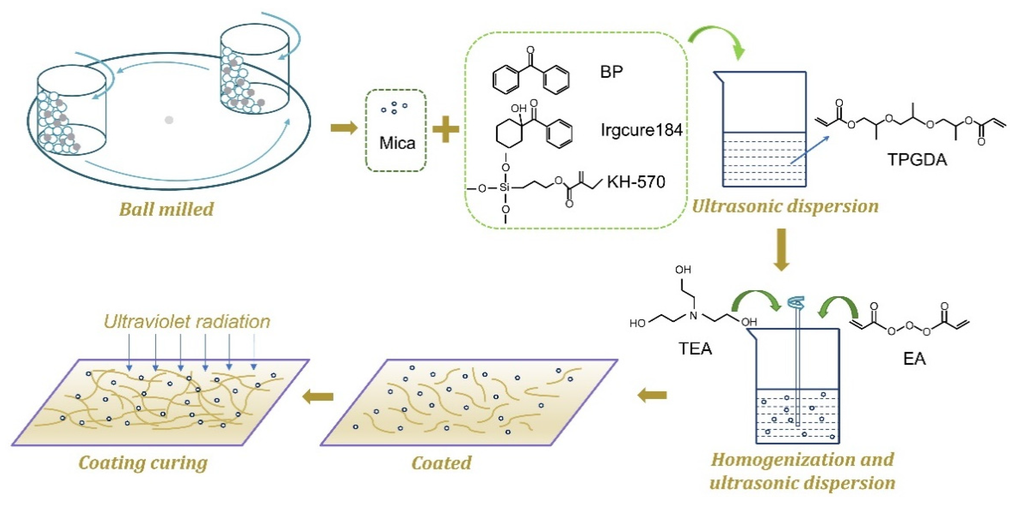
2.2. Sample Preparation

2.2.1. Ball-Milling of Mica Powders

20 g mica powder and 40 mL absolute ethyl alcohol were placed into a 250 mL zirconia jar with 200 g zirconia balls (Φ10 mm). These materials were mixed by a planetary high-energy ball mill (Pulverisette 4, Fritsch GmbH, Idar-Oberstein, Germany) at the disk speed of 300 r/min and the rotation-to-revolution speed ratio of -1.5. The slurries with balls were sifted through a 10-mesh sieve. After removing the balls, the obtained slurries were dried at 60 °C for 24 h.

2.2.2. Preparation of EA/Mica Composite Coatings

The formulations of the UV composite coatings used in this study are listed in Table 1. First, the solid BP, Irgcure184, mica powders, and KH-570 were added to the TPGDA solutions. The mixture was dispersed for 30 min by the ultrasonic cleaner. Then TEA and EA were added in sequence. A homogeneous coating was obtained after being dispersed in a high-speed homogenizer for 60 min and in an ultrasonic cleaner for 30 min. The obtained samples with un-ball-milled and ball-milled for 4, 8, 12, and 16 h mica powders were labeled as S-1, S-2, S-3, S-4, and S-5, respectively. The resulting coatings were spread onto a glass slide or a thin steel sheet with an OSP coating rod (10 μm, OSG System Products Corporation, Shenzhen, China). Finally, the wet films were cured by the UV curing machine (RW-UVAD301-501y, Shenzhen Run-wing Co. Ltd., Shenzhen, China) with the UV radiation intensity of 20 mW/cm2 and curing time of 60 s. The process of the coating preparation is illustrated in Figure 1.

3. Characterization

3.1. Laser Particle Size Analysis

Particle size distribution is a good method to show the change of particle size during ball-milling. The particle size distribution of mica powders was measured by laser size analyzer (Master sizer 3000; Malvern, Egham, Britain).

3.2. Scanning Electron Microscopy

The morphologies of mica powder particles and EA/mica composite coatings were observed by Ultra Plus scanning electron microscopy (Zeiss Electron Microscope Co., Ltd., Oberkochen, Germany). The surfaces of the samples were sprayed with gold to make them conductive before observation.

3.3. Fourier Transform Infrared Spectroscopy

The chemical structures of the composite coatings were studied by Fourier transform interferometer (Nicolet iS50, Thermo Nicolet, Waltham, MA, USA). The liquid mixtures were coated on the KBr wafer, then the uncured and cured coatings were analyzed by FTIR. The scanning range was 4000 to 400 cm−1.

3.4. X-Ray Diffraction Analysis

X-ray diffraction analysis adopted a computer-controlled X-ray diffractometer (X’Pert PRO, PANalytical, Almelo, Netherlands) at a speed of 8°/min from 5° to 90°at a generator voltage of 35 kV and a current of 25 mA.

3.5. Mechanical Testing

Tests of pencil hardness, adhesion, flexibility, and impact resistance were employed to investigate the mechanical properties of the coatings. The wet films (10 μm) were coated on the 0.28 mm thick sheet of tinplate to test the impact resistance, and coated on the 0.8 mm thick sheet steel to test pencil hardness, adhesion and flexibility. The mechanical properties of coatings were measured according to the corresponding standard test methods including pencil hardness (ISO 15184:1998), adhesion (ISO 2409:2020), flexibility (ISO 1519:2002), and impact resistance (Chinese Standard GB/T 1732-2020).

3.6. Electrochemical Impedance Spectroscopy

The measurement of electrochemical impedance spectroscopy was recorded by Solartron SI1260/SI1287 (Solartron Metrology). A three-electrode system was adopted. The counter electrode and the reference electrode were a platinum plate and a saturated calomel electrode, respectively. A steel plate coated with UV-curable coatings was used as the working electrode. The electrolyte solution was 3.5 wt.% NaCl solution. The sinusoidal perturbation voltage was 20 mV, and the measured frequency range was 105~10−2 Hz.

4. Results and Discussion

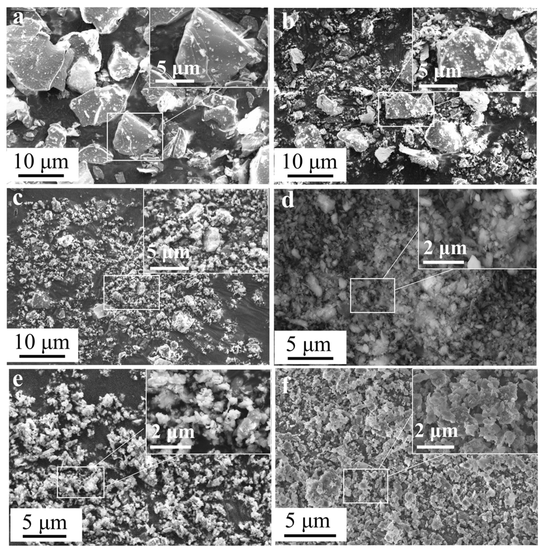
4.1. Morphologies of Mica Powders

As shown in Figure 2, the particle size of mica powders exhibited an obvious decreasing trend with the increase in the ball-milled time. As shown in Figure 2a, the original size of mica powders was about 10 μm without ball-milling. The particle size was significantly reduced after 4 h (Figure 2b), but the particle size distribution was not uniform, with particle size ranging from ~0.5 to ~10 μm. Figure 2c shows the morphologies of mica powders ball-milled for 8 h. The number of particles larger than 5 μm significantly decreased and most of the particles were below 2 μm. After being ball-milled for 12 h, the mica powder particles became significantly smaller and more uniform, and most were less than 2 μm (Figure 2d). There was a slight agglomeration, and some small particles were adsorbed on the surface of large particles (Figure 2e) when the mica was ball-milled for 16 h. This agglomeration was more obvious when the ball-milled time was 20 h (Figure 2f). The particle size became larger and the powders showed a flake structure. Figure 2 shows the reduction of the mica particle size during the ball-milling progress.

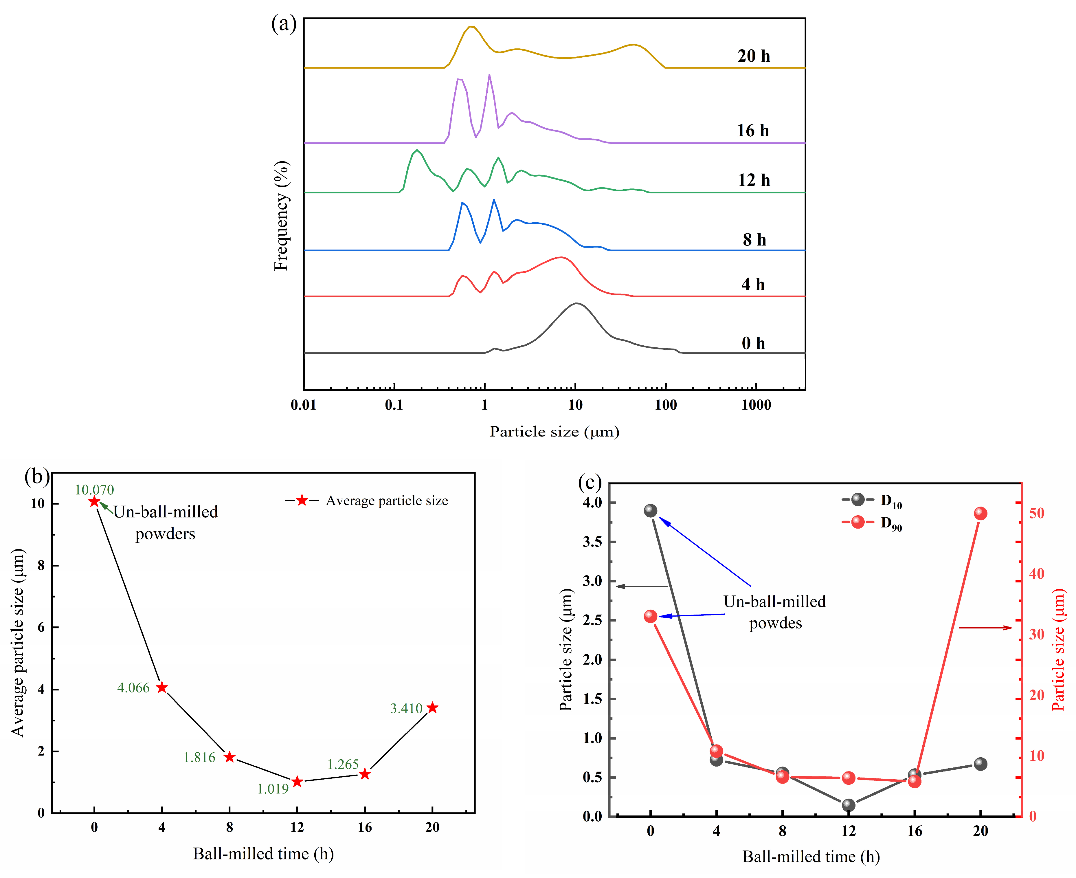
4.2. Particle Size Distribution of Mica Powders
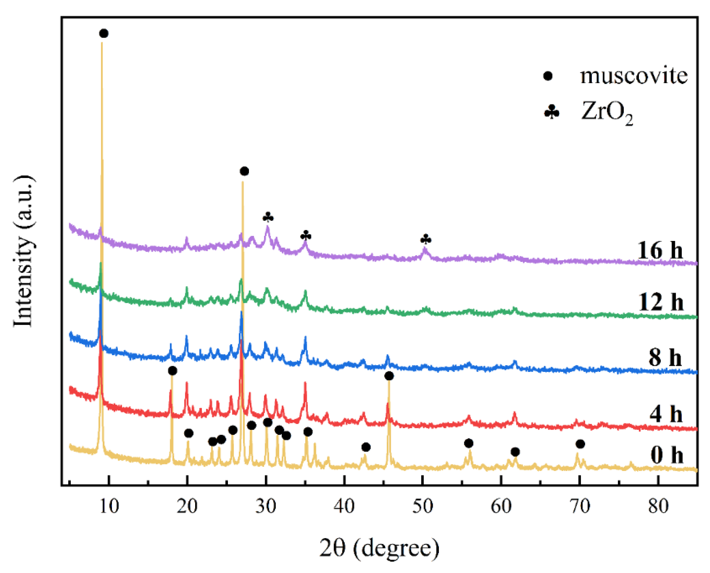
Figure 3 shows the changes of the particle size distribution (Figure 3a) and average particle size respective to the ball-milled time; the changes of D10, and D90 are shown in the inserts (Figure 3b). It was clearly shown that with the increase in ball-milled time, the peak of particle size distribution firstly moved to a smaller size region and then shifted back to a larger size region (Figure 3a), and D10 and D90 showed a tendency of decrease followed by an increase (Figure 3b). D10, D90, and average particle size decreased more steeply from un-ball-milled to ball-milled time of 4 h. Average particle size and D10 increased after dropping slowly from ball-milled time of 4 to 20 h. D90 approached a plateau from milling time of 4 to 16 h and had a great increase from 16 to 20 h. The increase of D10, D90, and average particle size suggested agglomeration, and it was verified as shown in Figure 2e,f. The results suggest 12 h may be the most suitable ball-milling time for obtaining the smallest and low agglomeration powders.
Due to the violent agglomeration of mica powder after ball milling for 20 h, only 0~16 h ball milling samples were chosen for the following experiments.

4.3. XRD Analysis

Figure 4 shows the XRD spectrum of un-ball-milled mica powders and powders ball-milled for different times. All diffraction peaks of mica powders corresponded to the muscovite in the JCPDS card. The intensity of mica powder’s characteristic diffraction peaks gradually decreased, the peaks of ball-milled mica products broadened, and even part of the diffraction peaks disappeared. This indicated that the particle size of mica was reduced with the increase in ball-milling time, and that the amorphous mica crystal gradually appeared. Combined with Figure 2, the particle size of mica was reduced and the layered structures were destroyed during the high-energy ball-milling process. The diffraction peaks of zirconia can be seen in the mica powder products after 16 h of ball-milling. This suggested that a small amount of zirconia in the ball-milled jar and balls was doped in the mica powders ball-milled products in the process of ball-milling.

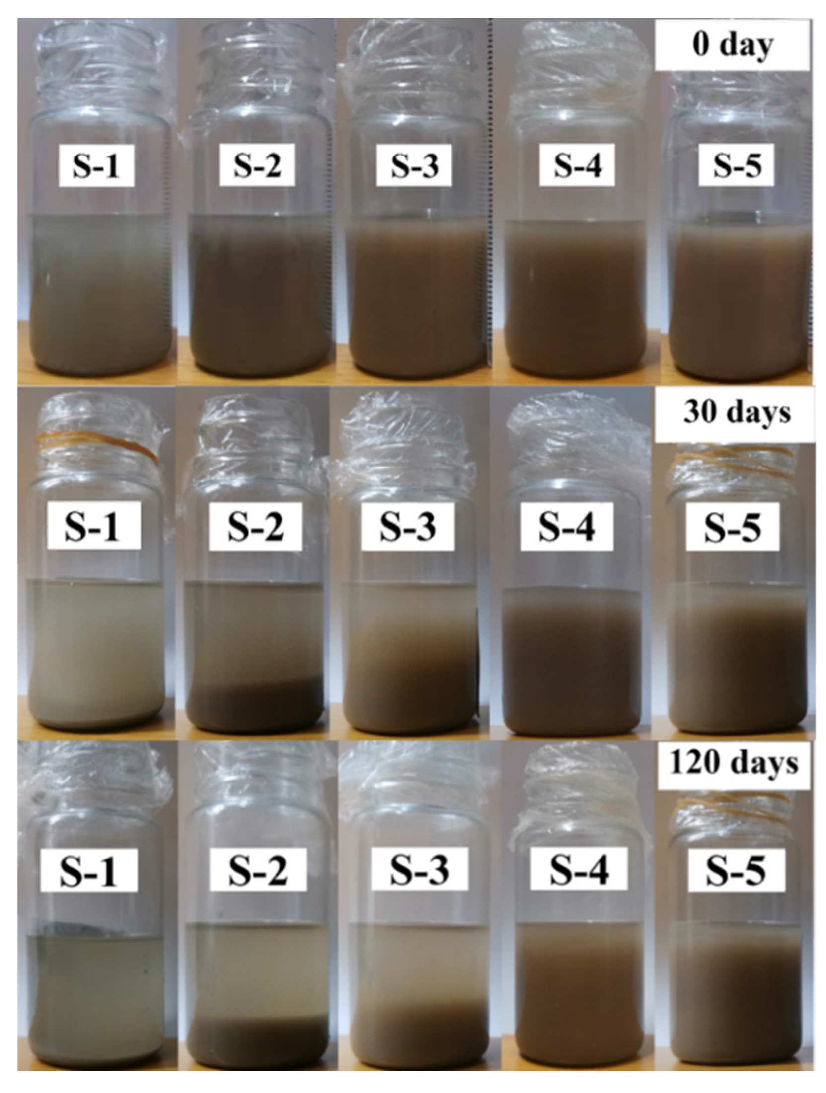
4.4. Stability of Liquid Mixtures
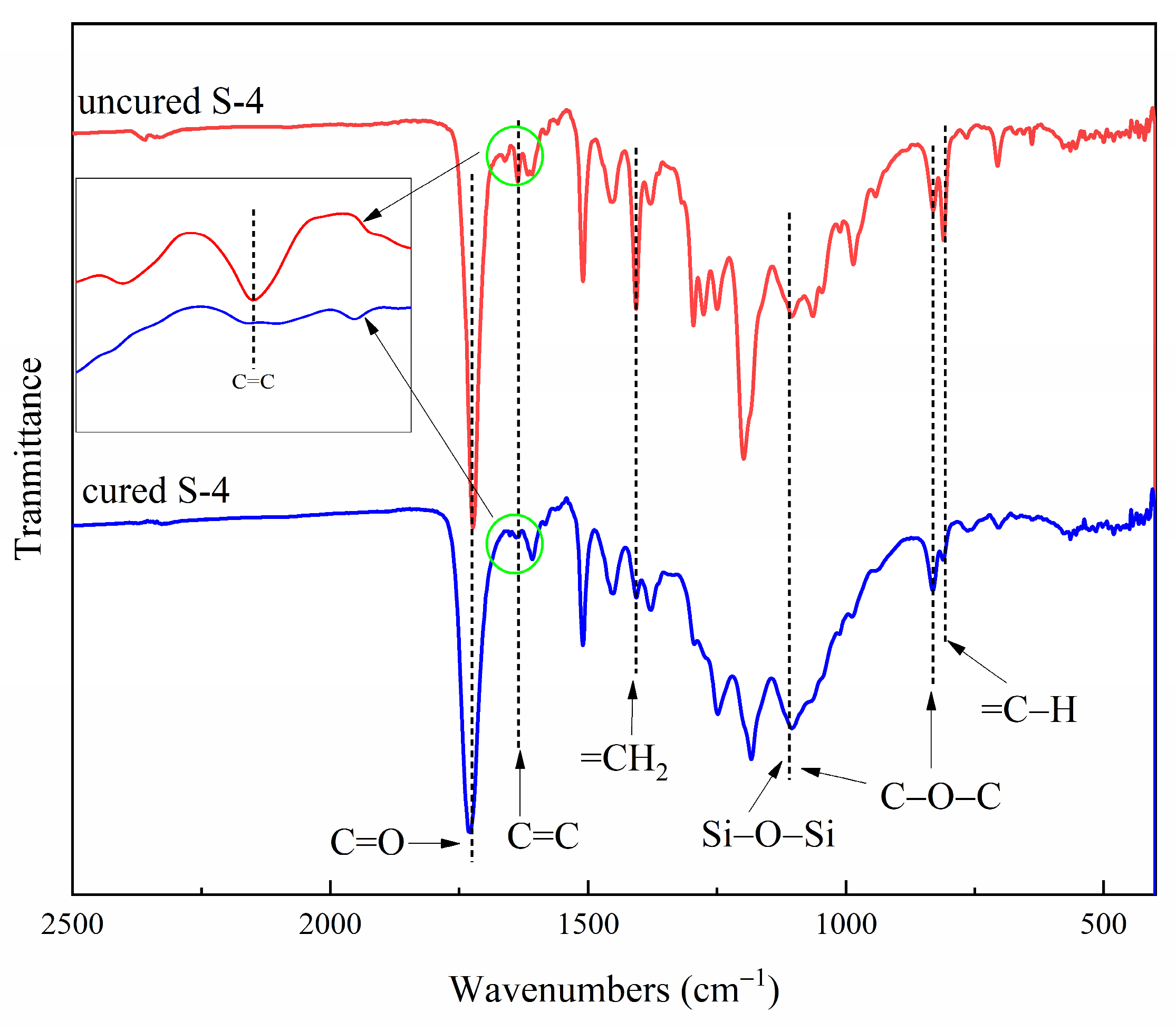
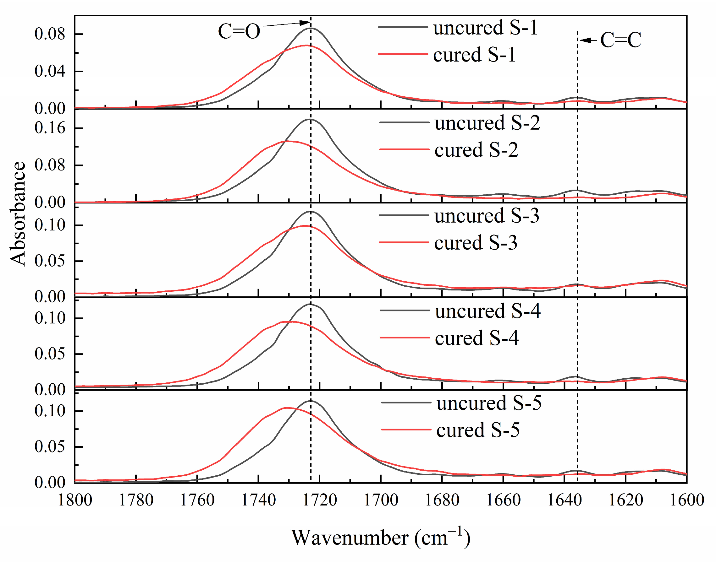
The uncured composite coatings with mica powders ball-milled at different times were obtained after homogenization. Figure 5 shows the digital photographs for these liquid mixtures placed at different times. The overall colors of the samples were different due to the different milling times. The coatings with mica powders un-ball-milled had higher transparency. The transparency of the coatings decreased visibly when the fillers were ball-milled mica powders. S-1, S-2, and S-3 were layered after being placed for 30 days. After being placed for 120 days, solid-liquid separation was more obvious in S-1, S-2, and S-3 and the upper layers were more limpid. However, the delamination of S-4 and S-5 was still not obvious. It was clear that the coatings with mica powders ball-milled 12 h or 16 h were more stable. It was speculated that the compatibility between fillers and epoxy acrylate coatings was improved because of the reduction of particle size [29,30,31]. The particle size of the mica powders was reduced by ball-milling, and the specific surface area of the mica powder particles with smaller particle size was larger. In the composite coatings, silane coupling agent KH-570 was added to improve the compatibility and dispersion between inorganic fillers and epoxy acrylate. Particles with larger specific surfaces bonded more to the silane coupling agent and had better compatibility with organic coatings [32,33,34]. The composite coatings where smaller particles were located were more stable because of their smaller gravity and larger specific surface area.

4.5. FTIR Analysis

The chemical structures of the composite coatings before and after being cured were checked by FTIR spectroscopy. Figure 6 shows FTIR spectra of the uncured S-4 and cured S-4. The characteristic absorption band at 1725 cm−1 was attributed to the stretching vibration of C=O bonds [35]. The absorption peak at 1635 cm−1 was C=C bonds linked to =C–H bonds at 810 cm−1 [36]. The bands at 1100 and 834 cm−1 were attributed to the trans-stretching and cis-stretching vibration of C–O–C bonds [37]. The spectra of cured S-4 show that the C=C bonds and =C–H bond were both almost absent, suggesting that the C=C bonds were consumed during the UV curing process. As shown in the FTIR spectra, the band intensity around 1100 cm−1 of the curve for cured S-4 was increased since the stretching vibration of Si–O–Si bonds located at such wave numbers coincided with the stretching vibration of the original C–O–C bonds [10,38]. These facts indicated that Si–O–Si structures were formed in the composite coatings, and the coatings polymerized under the irradiation of ultraviolet light [8,36,37].

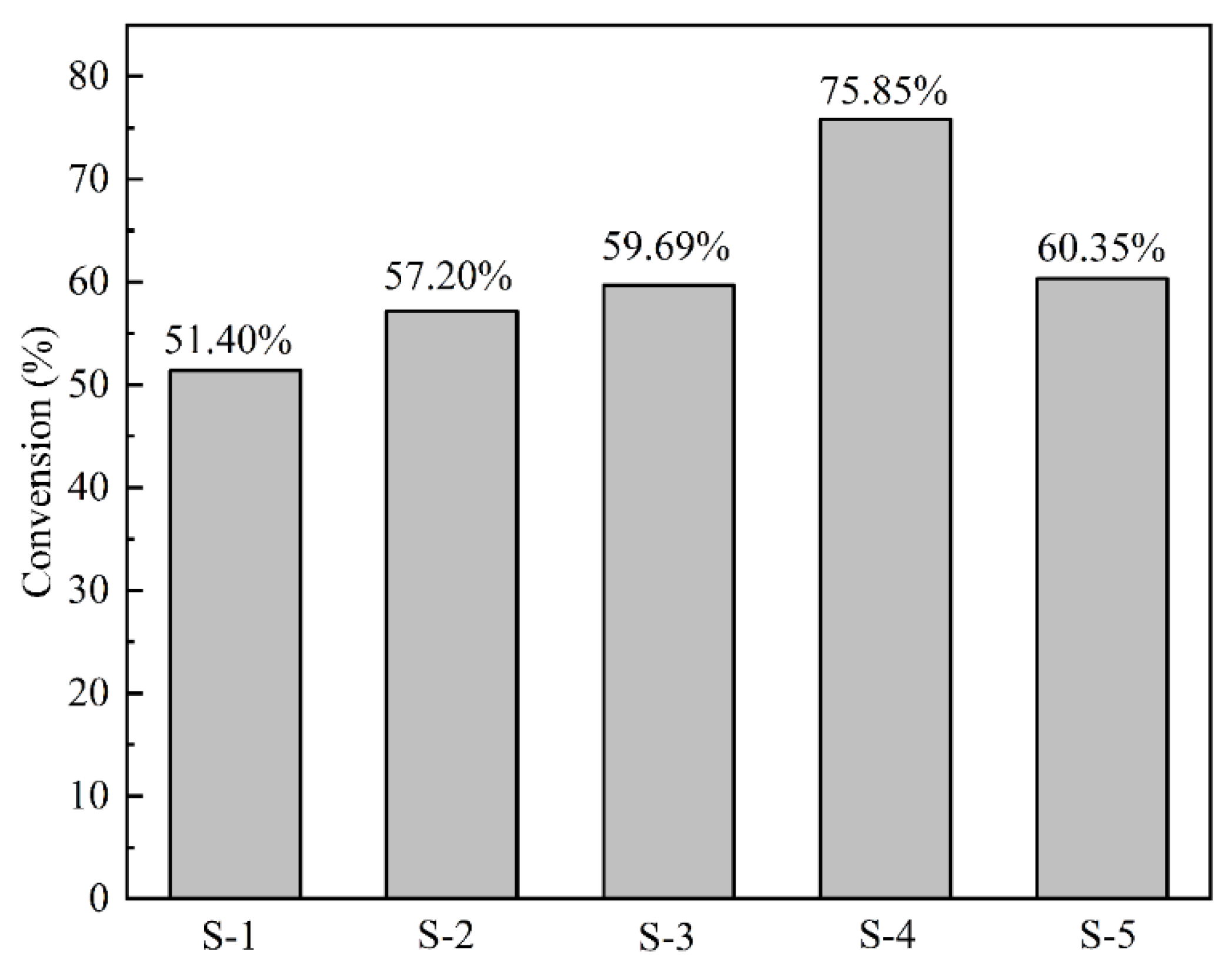
4.6. Conversion of C=C Bonds of Coatings

Figure 7 shows the FTIR spectra of uncured S-1, S-2, S-3, S-4, S-5 and cured S-1, S-2, S-3. S-4, S-5 in the range of 1800–1600 cm−1. The characteristic bands of C=O at 1725 cm−1 and the absorption peak of C=C bonds at 1635 cm−1 were exhibited. The absorption peaks at 1635 cm−1 almost disappeared after UV irradiation, and the C=C bonds had a blueshift due to the disappearance of the conjugation effect between C=C bonds and C=O bonds [39,40,41]. The C=O bonds were not affected after UV irradiation since the C=O bonds did not participate in the photopolymerization reaction. Herein, the stretching vibration of C=O bonds at 1735 cm−1 was a suitable candidate as an internal standard to calculate the conversion rate of C=C bonds [36,42,43]. The conversion rate of the C=C bonds equation is as follows:
Conversion = 100 %   ×   ( 1 A t S 0 A 0 S t )
where A0, S0 are the characteristic peak areas of C=C and C=O bonds in uncured coatings, respectively; At, St are the characteristic peak areas of C=C and C=O bonds in cured coatings, respectively.
The conversion rate of C=C bonds of the coatings after curing was calculated as shown in Figure 8. It was shown that compared with the samples containing un-ball-milled mica powders, the C=C bonds conversion rate of samples with ball-milled mica powders was increased. The C=C bonds conversion rate of coatings with ball-milled 12 h mica powders was the highest (75.85%). The conversion seemed to relate to the average particle size of the mica powders since it was increased when the particle size of mica powders was reduced. There are two possible reasons for this [13,35,39,44]: one is that the coatings with smaller particle size fillers have better fluidity, and the resistance to chain growth in the reaction was less; the other is that mica can also absorb ultraviolet light, and it can be reasonably speculated that the crystal structures of mica were destroyed in the process of particle size reduction, which weakened the ultraviolet absorption ability of mica [19] and changed the conversion rate of the C=C bond. The shielding effect of mica to ultraviolet light is mainly related to two factors, including the polarized light effect of crystal and the interlayer reflection and interference-effect. The lamellar mica has a high degree of orientation in a film and is aligned in parallel in the matrix, which made it easier to produce a total extinction phenomenon [8,18]. The photons received by the photoinitiator are reduced due to the absorption of ultraviolet light by mica. The absorption of ultraviolet radiation decreased due to the crystal structure and the lamellar structure of mica being destroyed during the high energy ball-milling process. Thus, the efficiency of UV curing was increased after mica powders were milled.

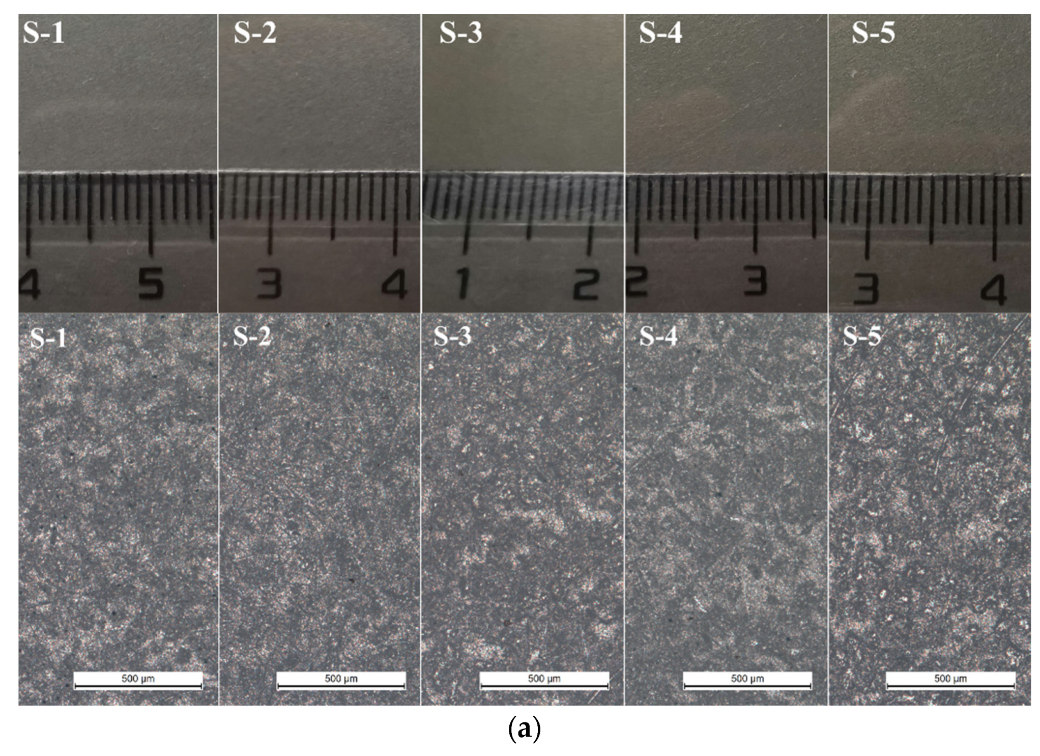
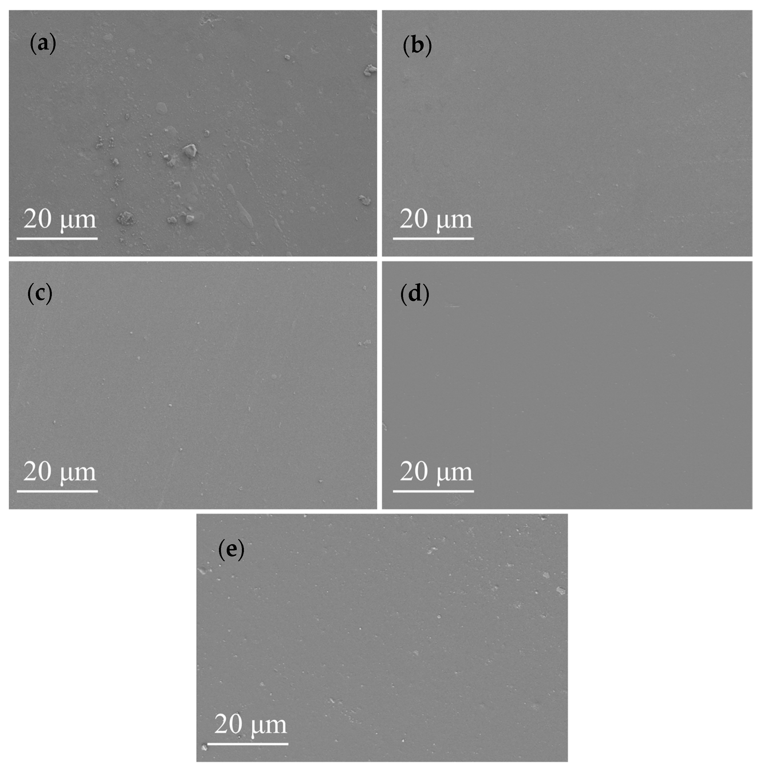
4.7. Morphologies of Coatings

The morphologies of the coatings modified by different ball-milled mica powders are shown in Figure 9a–e. As Figure 9 shows, the organic phase and inorganic phase had good compatibility in the coatings and no obvious phase separation can be observed. There were some large bulges on the surface of the coating with un-milled mica powders (Figure 9a) because the particles of un-ball-milled mica powders were large and raised on the surface. Figure 9b–e shows that the surface of coatings with ball-milled mica powders was smooth. As seen in Figure 9b–d, the mica particles were dispersed in the organic matrix uniformly without the agglomeration phenomenon. The agglomeration of mica particles is observed in Figure 9e. As with Figure 2e, mica powders agglomerated when ball-milled for 16 h. Even though the mica particles were treated by ultrasonic and homogenization methods during coating preparation, the mica particles did not disperse and continued to exist in the coatings as aggregates.

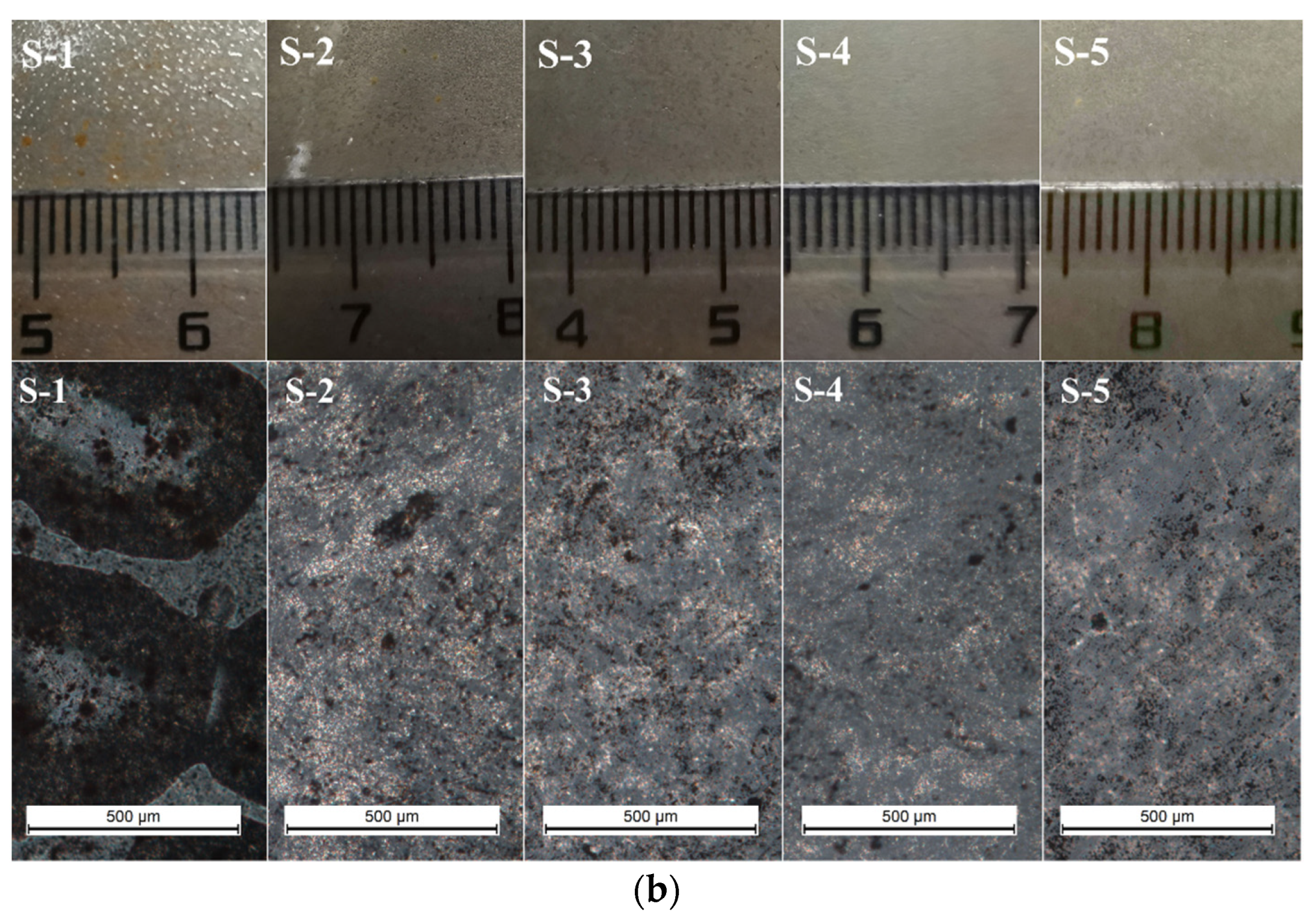
4.8. Mechanical Properties
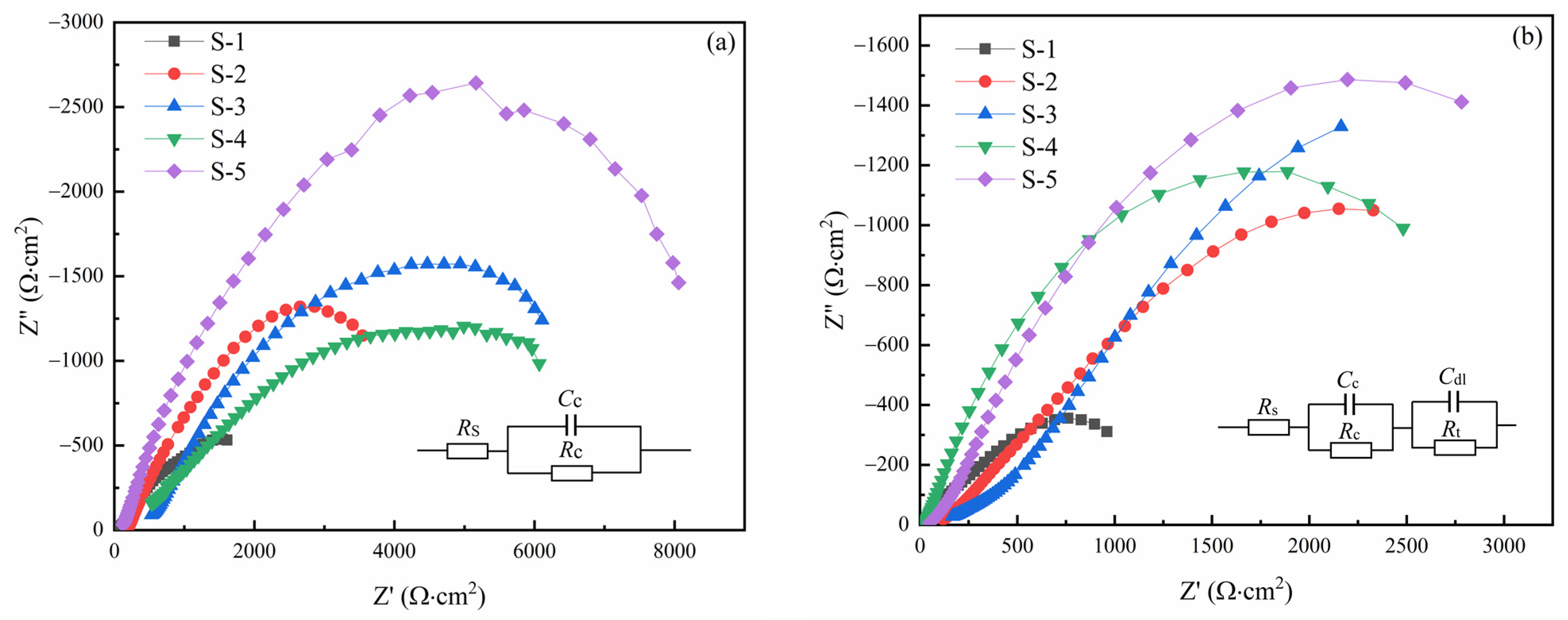
The mechanical properties of the UV curable coatings were evaluated by pencil hardness, adhesion, flexibility, and impact resistance test. As shown in Table 2, the coatings with mica particles exhibited excellent flexibility and good adhesion. The flexibility of samples S-1, S-2, S-3, S-4 and S-5 was <2 mm according to the mandrel bend tests. The results of adhesion tests showed that the particle size of mica fillers had little effect on adhesion. There were small differences in hardness and impact resistance of UV curable coatings modified with different particle size of mica powders. The mica particle size of sample S-4 was the smallest and sample S-4 showed the greatest hardness and impact resistance. This is mainly because that mica particles with large particle size were more difficult to disperse evenly in the coatings and large particles and uneven dispersion were more likely to produce defects. The mechanical properties of coatings are also related to the double bond conversion rate. The coatings with higher double bond conversion have better mechanical properties. As a result, coatings with smaller mica particles presented better performances in hardness and impact resistance.

4.9. EIS Analysis

Figure 10a shows the Nyquist plots of the coatings immersed in 3.5 wt% NaCl solution for 1 h and the equivalent circuit model. The plots showed a large capacitive loop, which corresponded to one time constant. The inserted circuit in Figure 10a was introduced to fit the experimental data in which Rs is the solution resistance; Cc and Rc are the coating capacitance and the coating resistance, respectively [45,46,47]. The Nyquist plots of the coatings immersed for 24 h displayed a double capacitive loop, and the experimental data were fitted by the equivalent circuit model shown in Figure 10b, in which Cc is the capacitance, and Cdl is the double-layer capacitance; Rs and Rt are the solution resistance and the charge transfer resistance, respectively [45,46,47]. With the increase in immersion time, the solution gradually penetrated into the interior of the organic coatings, and the protective effect of the coatings was significantly reduced after immersion for 24 h. When the aqueous solution passed through the organic coating and reached the interface between the coating and the metal matrix, a corrosive microcell was formed at the interface. The bonding force between the coating and the metal matrix was destroyed and the interface structure was changed.
Electrochemical parameters fitted from EIS results of coated systems at different immersion times are shown in Table 3. The resistance of the coatings with added ball-milled mica powders was higher than that with un-ball-milled powders. The resistance of the coating increased with the increase in ball-milling time of the fillers when the samples were immersed for 1 h. However, the resistance and charge transfer resistance of the coatings with ball-milled powders were almost the same when the samples were immersed for 24 h, but far greater than the coatings with un-ball-milled mica powders. The metal substrate had been corroded, and the effect of particle size on the coating resistance had been greatly weakened at this time, and all samples except S-1 had similar protective power to the metal substrate. It suggested that composite coatings with ball-milled mica powders provided better protection to the steel sheet compared with coatings with un-ball-milled mica powders.
Figure 11 shows the optical images of these samples before and after the EIS experiment. The coatings were transparent and smooth and there were no obvious differences between the samples before the EIS test (Figure 11a). After EIS tests, the surface of sample S-1 was obviously uneven (Figure 11b). The coating surfaces of samples S-2, S-3, S-4, S-5 were still smooth except that some small rusty spots were observed between the coating and the substrate (Figure 11b). When these samples were observed under an optical microscope, it was found that the corrosion of sample S-1 was obviously more violent than for other samples. Rusty spots were seen in all samples, indicating that the solution has passed through the coating and corroded the surface of the metal matrix. These results were consistent with the EIS test results. The rust spots of sample S-1 were larger than those of other samples which indicates that the composite coating with mica powders provides better protection to the metal matrix once again.

5. Conclusions

UV-curable organic-inorganic coatings were prepared by introducing different sized mica powders as fillers. The mica powders were put into a high-energy ball mill and ground for different times to obtain powders with different particle sizes. SEM and laser particle size analysis results showed that ball-milling effectively reduced the particle size of mica powders. The most suitable ball-milling time for obtaining the smallest and low agglomeration powders was 12 h due to the increase of average particle size and agglomeration that appeared for ball-milling times of 16 and 20 h. The crystal structures of the mica powders were destroyed by ball-milling, according to XRD analysis. Composite coatings were prepared by adding ball-milled mica powders into epoxy acrylate through a blending method. The delamination of the liquid mixtures after standing for 120 days showed that the stability of the composite coatings was related to the size of mica powders, and the coatings with a smaller size of mica powders had better stability. The chemical structures of the coatings before and after curing were studied by FTIR. The results showed that the reduction of particle size was beneficial to the conversion of C=C bonds. Mechanical properties tests suggested that the hardness and impact resistance of coatings was improved with the reduction of mica particle size. EIS results showed that the coatings with ball-milled mica powders had better protective performance than the coating with un-ball-milled mica powders.

Author Contributions

Data curation, formal analysis, and investigation, Y.D.; methodology, J.L.; writing—review and editing, Z.G.; methodology, project administration, and resources, X.X. All authors have read and agreed to the published version of the manuscript.

Funding

This work was supported by the National Natural Science Foundation of China (grant number U1908226) and National Key Research Development Program of China (grant number 2020YFC1909805).

Institutional Review Board Statement

Not applicable.

Informed Consent Statement

Not applicable.

Data Availability Statement

Data sharing is not applicable to this article.

Acknowledgments

This work was supported by the National Natural Science Foundation of China.

Conflicts of Interest

The authors declare no conflict of interest.

References

  1. Decker, C. Kinetic study and new applications of UV radiation curing. Macromol. Rapid Commun. 2002, 23, 1067–1093. [Google Scholar] [CrossRef]
  2. Lai, H.; Zhang, J.; Xing, F.; Xiao, P. Recent advances in light-regulated non-radical polymerisations. Chem. Soc. Rev. 2020, 49, 1867–1886. [Google Scholar] [CrossRef]
  3. Nakajima, T.; Shinoda, K.; Tsuchiya, T. UV-assisted nucleation and growth of oxide films from chemical solutions. Chem. Soc. Rev. 2014, 43, 2027–2041. [Google Scholar] [CrossRef] [PubMed]
  4. Vitale, A.; Trusiano, G.; Bongiovanni, R. UV-curing of adhesives: A critical review. In Progress in Adhesion and Adhesives; John Wiley & Sons, Inc.: Hoboken, NJ, USA, 2018; pp. 101–154. [Google Scholar] [CrossRef]
  5. Sangermano, M. UV Cured Nanostructured Epoxy Coatings. Epoxy Polymers: New Materials and Innovations; Wiley VCH: Weinheim, Germany, 2010; pp. 235–250. [Google Scholar] [CrossRef]
  6. Liu, F.; Liu, A.; Tao, W.; Yang, Y. Preparation of UV curable organic/inorganic hybrid coatings-a review. Prog. Org. Coat. 2020, 145, 105685. [Google Scholar] [CrossRef]
  7. Cong, W.W.; Zhou, Z.J.; Song, S.X.; Ge, C.C. Fabrication and evaluation of the nano-ceramics modified epoxy coatings. Key Eng. Mater. 2008, 368-372, 1294–1296. [Google Scholar] [CrossRef]
  8. Shen, J.; Ji, G.; Hu, B.; Huang, Y. Effect of filler size and surface treatment on impact and rheological properties of wollastonite-polypropylene composite. J. Mater. Sci. Lett. 1993, 12, 1344–1345. [Google Scholar] [CrossRef]
  9. Wang, Y.; Liu, F.; Xue, X. Synthesis and characterization of UV-cured epoxy acrylate/POSS nanocomposites. Prog. Org. Coat. 2013, 76, 863–869. [Google Scholar] [CrossRef]
  10. Yari, H.; Rostami, M. Enhanced weathering performance of epoxy/ZnO nanocomposite coatings via functionalization of ZnO UV blockers with amino and glycidoxy silane coupling agents. Prog. Org. Coat. 2020, 147, 105773. [Google Scholar] [CrossRef]
  11. Ingrosso, C.; Corcione, C.E.; Striani, R.; Comparelli, R.; Striccoli, M.; Agostiano, A.; Curri, M.L.; Frigione, M. UV-curable nanocomposite based on methacrylic-siloxane resin and surface-modified TiO2 nanocrystals. ACS Appl. Mater. Interfaces 2015, 7, 15494–15505. [Google Scholar] [CrossRef]
  12. Wang, X.; Feng, Y.; Zhang, L.; Protsak, I.; Jamali, R.; Shu, Y.; Pal, P.; Wang, Z.; Yang, J.; Zhang, D. Fast-cured UV-LED polymer materials filled with high mineral contents as wear-resistant, antibacterial coatings. Chem. Eng. J. 2020, 382, 122927. [Google Scholar] [CrossRef]
  13. Yang, Z.; Wu, J.; Ma, G.; Hou, C.; Niu, Y.; Duan, H.; Hao, X. Effect of the particle sizes of silica on the properties of UV-curing matting coatings. J. Coat. Technol. Res. 2020, 18, 183–192. [Google Scholar] [CrossRef]
  14. Kim, D.; Lim, M.; Kim, I.; Seo, J.; Han, H. Preparation and properties of hydrophobic layered silicate-reinforced UV-curable poly(urethane acrylate) nanocomposite films for packaging applications. Prog. Org. Coat. 2014, 77, 1045–1052. [Google Scholar] [CrossRef]
  15. Pavlacky, E.; Webster, D.C. Anin situintercalative polymerization method for preparing UV curable clay-polymer nanocomposites. J. Appl. Polym. Sci. 2015, 132. [Google Scholar] [CrossRef]
  16. Christenson, H.K.; Thomson, N.H. The nature of the air-cleaved mica surface. Surf. Sci. Rep. 2016, 71, 367–390. [Google Scholar] [CrossRef] [Green Version]
  17. Şentürk, E.; Akçakale, N.; Okutan, M. Conductivity mechanism of mica powders inlaid elastomer based materials. J. Alloy. Compd. 2016, 686, 43–47. [Google Scholar] [CrossRef]
  18. Andraschek, N.; Wanner, A.J.; Ebner, C.; Riess, G. Mica/Epoxy-Composites in the electrical industry: Applications, composites for insulation, and investigations on failure mechanisms for prospective optimizations. Polymers 2016, 8, 201. [Google Scholar] [CrossRef]
  19. Pan, X.-F.; Gao, H.-L.; Lu, Y.; Wu, C.-Y.; Wu, Y.-D.; Wang, X.-Y.; Pan, Z.-Q.; Dong, L.; Song, Y.-H.; Cong, H.-P.; et al. Transforming ground mica into high-performance biomimetic polymeric mica film. Nat. Commun. 2018, 9, 2974. [Google Scholar] [CrossRef] [Green Version]
  20. Wang, L.; Liu, Y.; Liu, G. Hydrophobic coating of mica by piranha solution activation, silanization grafting, and copolymerization with acrylate monomers. J. Appl. Polym. Sci. 2017, 134. [Google Scholar] [CrossRef]
  21. Jadhav, N.; Matsuda, T.; Gelling, V. Mica/polypyrrole (doped) composite containing coatings for the corrosion protection of cold rolled steel. J. Coat. Technol. Res. 2017, 15, 363–374. [Google Scholar] [CrossRef]
  22. Koreeda, T.; Matos, J. Thermal characterization of mica–epoxy composite used as insulation material for high voltage machines. J. Coat. Technol. Res. 2011, 106, 619–623. [Google Scholar] [CrossRef]
  23. Mondal, N.; Haque, N.; Dalai, S.; Chakravorti, S.; Chatterjee, B. Method for identifying ageing in epoxy-mica composite insulation used in rotational machines through modelling of dielectric relaxation. High Volt. 2020, 5, 184–190. [Google Scholar] [CrossRef]
  24. Omar, M.F.; Akil, H.M.; Ahmad, Z.A. Static and dynamic compressive properties of mica/polypropylene composites. Mater. Sci. Eng. A 2011, 528, 1567–1576. [Google Scholar] [CrossRef]
  25. Sreekanth, M.S.; Bambole, V.A.; Mhaske, S.T.; Mahanwar, P.A. Effect of Concentration of Mica on Properties of Polyester Thermoplastic Elastomer Composites. J. Miner. Mater. Charact. Eng. 2009, 08, 271–282. [Google Scholar] [CrossRef]
  26. Xia, L.; Wu, H.; Guo, S.; Sun, X.; Liang, W. Enhanced sound insulation and mechanical properties of LDPE/mica composites through multilayered distribution and orientation of the mica. Compos. Part A Appl. Sci. Manuf. 2016, 81, 225–233. [Google Scholar] [CrossRef]
  27. Gao, P.; Xue, X.X. Effect of mica powder content on properties of epoxy acrylate composite coating, materials protection. Mater. Protect. 2011, 3, 47–50. [Google Scholar] [CrossRef]
  28. Cheong, I.-W.; Kim, H.-S.; Hwang, D.-S.; Yoo, H.-J.; Kim, J.-T.; Lee, J.-R.J.C.S. Technology, preparation and characterization of muscovite Mica/UV coating materials for steel, corrosion science and technology. Corros. Sci. Technol. 2010, 9, 265–269. [Google Scholar] [CrossRef]
  29. Gu, Y.; Tang, B.; He, L.; Yang, F.; Wang, H.; Ling, J. Compatibility of cured phase-inversion waterborne epoxy resin emulsified asphalt. Constr. Build. Mater. 2019, 229, 116942. [Google Scholar] [CrossRef]
  30. Shang, X.-Y.; Zhu, Z.-K.; Yin, A.J.; Ma, X.-D. Compatibility of soluble polyimide/silica hybrids induced by a coupling agent. Chem. Mater. 2002, 14, 71–77. [Google Scholar] [CrossRef]
  31. Wang, F.; Liu, Y.; Zhang, Y.; Hu, S. Experimental study on the stability of asphalt emulsion for CA mortar by laser diffraction technique. Constr. Build. Mater. 2012, 28, 117–121. [Google Scholar] [CrossRef]
  32. Chen, S.; Qu, W.; Xu, K. Application of silane coupling agent. Silicone Mater. 2003, 17, 28–31. [Google Scholar] [CrossRef]
  33. Lin, J.; Siddiqui, J.A.; Ottenbrite, R.M. Surface modification of inorganic oxide particles with silane coupling agent and organic dyes. Polym. Adv. Technol. 2001, 12, 285–292. [Google Scholar] [CrossRef]
  34. Aziz, T.; Ullah, A.; Fan, H.; Jamil, M.I.; Khan, F.U.; Ullah, R.; Iqbal, M.; Ali, A.; Ullah, B. Recent progress in silane coupling agent with its emerging applications. J. Polym. Environ. 2021, 29, 3427–3443. [Google Scholar] [CrossRef]
  35. Xu, J.; Jiang, Y.; Zhang, T.; Dai, Y.; Yang, D.; Qiu, F.; Yu, Z.; Yang, P. Synthesis of UV-curing waterborne polyurethane-acrylate coating and its photopolymerization kinetics using FT-IR and photo-DSC methods. Prog. Org. Coat. 2018, 122, 10–18. [Google Scholar] [CrossRef]
  36. Wang, Y.; Liu, F.; Xue, X. Morphology and properties of UV-curing epoxy acrylate coatings modified with methacryl-POSS. Prog. Org. Coat. 2015, 78, 404–410. [Google Scholar] [CrossRef]
  37. Liu, F.; Wang, Y.; Xue, X.; Yang, H. UV curable EA-Si hybrid coatings prepared by combination of radical and cationic photopolymerization. Prog. Org. Coat. 2015, 85, 46–51. [Google Scholar] [CrossRef]
  38. Corcione, C.E.; Striani, R.; Frigione, M. Microgel modified UV-cured methacrylic-silica hybrid: Synthesis and characterization. Materials 2013, 6, 3805–3825. [Google Scholar] [CrossRef] [PubMed] [Green Version]
  39. Han, Y.-H.; Taylor, A.; Mantle, M.D.; Knowles, K.M. UV curing of organic–inorganic hybrid coating materials. J. Solgel Sci. Technol. 2007, 43, 111–123. [Google Scholar] [CrossRef]
  40. Medda, S. Inorganic–organic hybrid coatings on polycarbonate. Spectroscopic studies on the simultaneous polymerizations of methacrylate and silica networks. J. Non Cryst. Solids 2003, 318, 149–156. [Google Scholar] [CrossRef]
  41. Jeong, S.; Jang, W.-H.; Moon, J. Fabrication of photo-patternable inorganic–organic hybrid film by spin-coating. Thin Solid Films 2004, 466, 204–208. [Google Scholar] [CrossRef]
  42. Park, Y.-J.; Lim, D.-H.; Kim, H.-J.; Park, D.-S.; Sung, I.-K. UV- and thermal-curing behaviors of dual-curable adhesives based on epoxy acrylate oligomers. Int. J. Adhes. Adhes. 2009, 29, 710–717. [Google Scholar] [CrossRef]
  43. Wang, J.Z.; Bogner, R.H. Techniques to monitor the UV curing of potential solvent-free film-coating polymers. Int. J. Pharm. 1995, 113, 113–122. [Google Scholar] [CrossRef]
  44. Zhang, J.-Y.; Windall, G.; Boyd, I.W. UV curing of optical fibre coatings using excimer lamps. Appl. Surf. Sci. 2002, 186, 568–572. [Google Scholar] [CrossRef]
  45. Zhang, J. EIS data analysis for evaluation of protective property of organic coatings. Corros. Sci. Prot. Technol. 1994, 6, 318–325. [Google Scholar]
  46. Dhoke, S.K.; Khanna, A. Electrochemical impedance spectroscopy (EIS) study of nano-alumina modified alkyd based waterborne coatings. Prog. Org. Coat. 2012, 74, 92–99. [Google Scholar] [CrossRef]
  47. Liu, J.; Lu, Z.; Zhang, L.; Li, C.; Ding, R.; Zhao, X.; Zhang, P.; Wang, B.; Cui, H. Studies of corrosion behaviors of a carbon steel/copper-nickel alloy couple under epoxy coating with artificial defect in 3.5 wt.% NaCl solution using the WBE and EIS techniques. Prog. Org. Coat. 2020, 148, 105909. [Google Scholar] [CrossRef]
Figure 1. The process illustration of the coating preparation.
Coatings 12 00098 g001
Figure 2. Morphologies of un-ball-milled (a), and ball-milled 4 h (b), 8 h (c), 12 h (d), 16 h (e) and 20 h (f) mica powders.
Coatings 12 00098 g002
Figure 3. Particle size of mica (a) Particle size distributions, (b) average particle size of mica at different ball-milling times, and (c) the relationship of D10 and D90 with the milling time.
Coatings 12 00098 g003
Figure 4. X- ray diffraction diagrams of mica powders with different ball-milling time.
Coatings 12 00098 g004
Figure 5. Digital photographs of the mixed coatings with different ball-milling times.
Coatings 12 00098 g005
Figure 6. FTIR spectra of the uncured S-4 and cured S-4.
Coatings 12 00098 g006
Figure 7. FTIR spectra of coatings before and after being cured.
Coatings 12 00098 g007
Figure 8. Conversion rate of C=C bonds of coatings.
Coatings 12 00098 g008
Figure 9. SEM micrographs of coatings with mica powders ball-milled for different times (a) 0 h, (b) 4 h, (c) 8 h, (d) 12 h, (e) 16 h.
Coatings 12 00098 g009
Figure 10. Nyquist plots of different coatings in 3.5% NaCl solution for immersion time of 1 h (a) and 24 h (b).
Coatings 12 00098 g010
Figure 11. (a) Optical images of samples before electrochemical impedance spectroscopy test; (b) Optical images of samples after electrochemical impedance spectroscopy test.
Coatings 12 00098 g011aCoatings 12 00098 g011b
Table 1. Formulation of UV curable EA/mica coatings.
ComponentEATPGDAKH-570TEABPIrgcure184Mica
Weight (g)505040.9533
Table 2. Pencil hardness, adhesion, flexibility, and impact resistance of coatings.
SamplePencil HardnessAdhesionFlexibility (mm)Impact Resistance (cm)
S-13H1<25
S-23H-4H1<210
S-33H-4H1<210
S-44H1<215
S-54H1<210
Table 3. Fitting electrochemical parameters of different immersion times.
Sample1 h24 h
Rc (Ω‧cm2)Rc (Ω‧cm2)Rt (Ω‧cm2)
S-14106736463
S-2616737433806
S-3792633113409
S-411,80034423404
S-512,00034233422
Publisher’s Note: MDPI stays neutral with regard to jurisdictional claims in published maps and institutional affiliations.

