Article

Evolution of the Surface Structure and Functional Properties of the Electroconducting Polymer Coatings onto Porous Films

by
Galina Kazimirovna Elyashevich
*,
Dmitry Igorevich Gerasimov
,
Ivan Sergeevich Kuryndin
,
Viktor Konstantinovich Lavrentyev
,
Elena Yurievna Rosova
and
Milana Ernestovna Vylegzhanina
Institute of Macromolecular Compounds, Russian Academy of Sciences, Bolshoy pr., 31, 199004 Saint-Petersburg, Russia
*
Author to whom correspondence should be addressed.
Coatings 2022, 12(1), 51; https://doi.org/10.3390/coatings12010051
Submission received: 25 November 2021 / Revised: 23 December 2021 / Accepted: 28 December 2021 / Published: 2 January 2022
(This article belongs to the Special Issue Functional Polymer Films and Their Applications)

Abstract

:
Composite systems containing electroconducting polymer coatings (polyaniline and polypyrrole) applied to porous films of semicrystalline polymers (polyethylene, polypropylene, and polyvinylidene fluoride) have been prepared. Porous supports were obtained in the process based on polymer melt extrusion with subsequent annealing, uniaxial extensions, and thermal stabilization. Conducting coatings were formed by the oxidative polymerization of the monomers directly onto the porous supports. The structure (overall porosity, permeability, pore sizes, factor of orientation) and morphology (specific surface and character of the film surface) of the supports were characterized by sorptometry, filtration porosimetry, atomic force microscopy (AFM), and X-ray scattering techniques. It was observed that the porous supports have a strongly developed relief surface which is formed in the pore formation process. It was proven by scanning electron microscopy (SEM) that the porous supports have an oriented structure, and the surface of the composites is defined by the morphology inherent in the conducting component. It was shown that these composites (porous support/conducting coating) demonstrate electric conductivity both along the surface and between surfaces. It was demonstrated that the deposition of conducting coatings leads to an increase in the water wettability of the composites compared with pronounced hydrophobic supports. The composites are characterized by good adhesion between components due to a relief film surface as well as high mechanical strength and elasticity provided by the oriented character of the supports.

Graphical Abstract

1. Introduction

Intrinsically conducting polymers represent one of the most attractive substances for the elaboration of smart materials in numerous potential applications. Due to their unique electrical, optical, and electrooptical properties, they may be used in batteries, electrochromic displays, ion-exchange materials, membranes, sensors, corrosion protection coatings, antistatic and biomaterials, etc. [1,2,3,4,5,6]. A distinctive feature of the conducting polymers which distinguishes them from classical conductors consists in the possibility to prepare various configurations via a modification with various dopants or combination with desired supports in the hybrid systems. Composite membranes modified with intrinsically conducting polymers may acquire novel separation capabilities. The changes of characteristics of these polymers as a result of chemical or electrochemical doping permit to use them for obtaining composite systems with a wide spectrum of functional properties [7,8,9].
Polypyrrole (PPy) and polyaniline (PANI) as conducting polymers are very promising components for the preparation of smart and stimuli-responsible materials due to their high specific conductivity, good chemical stability, and compatibility with polymer supports. However, potential applications of these polymers are restricted by low processability and poor mechanical properties, i.e., low strength, high brittleness, and low solubility in common solvents. The most efficient solution for this problem is to elaborate composite systems where a polymer support provides good mechanical properties, and a conducting polymer is used as an active component [10,11,12].
Supports of large-scale polymers may be considered as universal matrices for composite preparation due to their low cost and wide availability of raw materials, high industrial processing capacity, mechanical strength, and chemical stability. For some applications (for example, membranes), the porous films of these polymers are especially useful because they provide the possibility to form the space continuous conducting phase and to reach high conductivity [13,14].
The most widespread techniques to prepare the porous films are based on the mechanism of phase inversion (including thermally induced phase separation) and crazing [15,16]. In these cases, the pores are generated by the extraction of a solvent, namely the evaporation of solution and as a result the solid porous film formation. Controlling the morphology, it is possible to produce membranes with various pore sizes and permeability. This process has two main drawbacks: solvent contamination and expensive solvent recovery. Porous films of semicrystalline polymers may be produced by the less expensive and solvent-free method [17,18,19]. This technique is based on melt extrusion, and it permits to produce highly permeable porous films from the cheapest and industrially produced polymers, which are characterized by high chemical stability. These polymers are also resistant to heat and light effects and possess good water and moisture resistance. The films prepared by this procedure have important advantages over porous samples prepared by crazing and phase inversion, namely the considerably higher permeability and presence of larger pores. They may be effectively used as flexible substrates for the incorporation of active components of a different chemical structure and the production of composite systems [20,21].
The porous structure of the supports gives a wider field of application for electroactive composite materials in membrane technologies [22,23]. Several strategies have been investigated to elaborate conductive polymeric systems using PPy and PANI [24,25,26,27]. These materials were prepared using in situ oxidative polymerization or electrochemical methods in the presence of natural or synthetic insulating matrices as blends or coatings on the films and fibers including nanofibers [28,29]. It was noted that the supports with a porous structure offer advantages in terms of the functional properties of composites due to their very large surface area to volume ratio of the porous structure and high density of active sites, associated with the properties of conductive polymers.
One of the most important directions for the application of porous materials is devices for energy accumulation, conversion, and storage [30,31]. Such devices include various types of lithium-ion batteries, fuel cells, flow batteries, etc. The integral elements of such devices (especially in portable versions) are polymer films as separators (membranes), which provide permeability for ion flux but obstacles to the electric contact of electrodes. Synthetic large-scale polymers with good chemical resistance to electrolytes (inorganic acids and alkalis, and organic media), polyolefins (polyethylene, polypropylene etc.) and fluorinated polymers such as polyvinylidene fluoride, constitute the most effective basis for such materials. Moreover, porous substrates of these polymers can be considered as “molecular or nano-containers” for the introduction of active functional components. For example, the role of the support as the separator can be expanded by conductive polymer coating since these layers can simultaneously operate as modified electrodes. However, the membranes of these polymer supports are poorly wetted by water that leads to the limitation of their application in water media [32,33]. The conducting polymer coatings are capable to provide an increase in hydrophilicity for composites. Thus, the combination of an elastic porous film with a conductive polymer makes it possible to obtain hybrid materials with new functional properties.
In this work, the porous films of polyolefins, namely polyethylene (PE) and polypropylene (PP), and fluoride polymer, polyvinylidene fluoride (PVDF), were chosen as elastic supports for the formation of conducting polymer coatings. These materials, the cheapest and large-scale products, are characterized by high chemical stability to aggressive media, including organic solvents, acids, and alkalis. They are also resistant to heat and light effects and possess good water and moisture resistance. Being flexible-chain crystallizable thermoplastic polymers, they may be processed by melt technologies. During the crystallization process, these polymers are capable of forming a large number of different supramolecular structures, which determine the functional properties of materials based on them. Additionally, PVDF is a very attractive material due to its piezoelectric activity. In this paper, the porous supports were prepared via the process based on the melt extrusion, which is a very effective and ecologically safe procedure because it does not use toxic solvents or admixtures [34,35,36].
PPy and PANI were used as conducting coatings on the surface of porous films to form electroactive composites. These conducting polymers were chosen as the active component of the composites because of their unique optical, electric, and chemical properties. Further, PANI and PPy are the most promising conducting polymers due to their high inherent conductivity and relatively simple preparation procedures, via electrochemical or chemical synthesis. These polymers are characterized by low-toxicity and high stability to environmental impact [37]. The problem when preparing these composites is the low adhesive capability of both components (ordinary “smooth” supports and electroactive polymer) to other polymer or low molecular substances. The goal of this work was to prepare the porous supports of PE, PP, and PVDF and composites, containing the conductive polymer coatings (PANI and PPy) applied to these supports, to investigate the structure development of the samples in the process of formation and to characterize the functional properties of the composites.

2. Materials and Methods

Microporous films were prepared via the process based on melt extrusion using commercial grade linear polyethylene (HDPE 276 Stavrolene, Budyonnovsk, Russia, Mw = 170,000, melting point Tm = 132 °C), isotactic polypropylene (PPG 1035 Stavrolene, Budyonnovsk, Russia, Mw = 380,000, Tm = 172 °C), and PVDF (Kynar-720, Atofina Chemicals Inc., Philadelphia, PA, USA, Mw = 190,000, Tm = 168 °C).
Porous films were characterized by the overall porosity P, which was calculated as
P = [(ρ−ρp)/ρ] × 100%
where ρ is the density of the dense films and ρp is the density of the porous films, which were measured gravimetrically.
Specific surfaces and pore size distribution of porous supports and composites were measured by the N2 adsorption/desorption isotherms on Analyzer “Sorbtometr-M” (Katakon, Novosibirsk, Russia) using the Brunauer–Emmett–Teller (BET) and Barrett–Joyner–Halenda (BJH) methods.
The permeability of the porous films to liquids and through pore size distributions were determined by filtration porosimetry [38] measuring the flow rate of liquid in filtration cell under the pressure. Permeability G was calculated as
G = V/(A × t × p × K)
where V denotes the volume of the liquid flowing through the porous films during time t under the pressure p; A is the square of the sample, K is the constant characterizing the filtration cell resistance to liquid flow.
Wide-angle X-ray scattering studies were performed using a DRON 2.0 diffractometer (Burevestnik, Saint-Petersburg, Russia) with CuKα radiation. The recording was carried out in transmission mode. To determine the orientation degree of the samples, the azimuthal curves of intensity for reflection (110) were obtained. The degree of orientation was estimated by calculating the orientation factor through Equation (3) [39]:
f c = 3 c o s 2 φ 1 2
where φ is the angle between the extrusion direction and the crystalline chain axis.
The morphology of the samples was studied by scanning electron microscopy using a SUPRA-55VP (ZIESS, Oberkochen, Germany) and atomic force microscopy using a “Nanotop NT-206” (Mikrotestmashines, Gomel, Belarus). The measurements were carried out in contact modes under atmospheric conditions using FMG01 silicon cantilevers with a stiffness coefficient of k = 1.5–5.0 N/m and the radius of curvature of the tip less than 10 nm. The experimental data were processed with the use of the program Surface Explorer (version).
The wettability of the sample surface was determined by the contact angle technique using a DSA30 instrument (KRUSS, Hamburg, Germany). Distillate water was used as a wetting liquid.
The conducting composites were obtained by the in situ oxidative polymerization of monomer directly on the surface of the porous support.
To form PANI coating, the supports were placed into the reaction mixture containing 0.2 M solution of aniline hydrochloride as monomer in 1 M HCl water solution and 0.25 M solution of ammonium peroxidisulfate ((NH4)2S2O8) in 1M HCl water solution as oxidant. The porous films were placed in the polymerization mixture for 24 h. Then, the resulting composites were taken out, rinsed with 0.1 M HCl, and dried in air.
The layers of PPy were formed onto the supports surface by polymerization of monomer (pyrrole) in the solution of the mixture methanol/water in equal volumes. As oxidant, the solution of FeCl3 was used. The methanol/water mixture was chosen as the optimal solvent which ensures the best wettability of the supports surface.
The content x of conducting polymer in the prepared composites was calculated as
x = Wcond/(Wpor + Wcond) × 100%
where Wpor is the mass of the initial porous film and ΔWcond is the mass difference between the composite sample and support.
Electrical conductivity was measured at room temperature by the DC four-probe van der Pauw method for sheet (σs) conductivity and the two-disk method for volume (σv) conductivity, using a P-30 potentiostat (Elins, Moscow, Russia).
Mechanical characteristics of the samples were measured using a Tensile Test Machine 2166 R5 (Tochpribor, Ivanovo, Russia). The stress–strain curves at extension were used to measure tensile strength, elastic modulus, and break elongation.

3. Results and Discussion

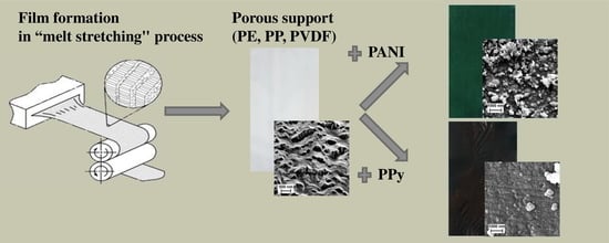
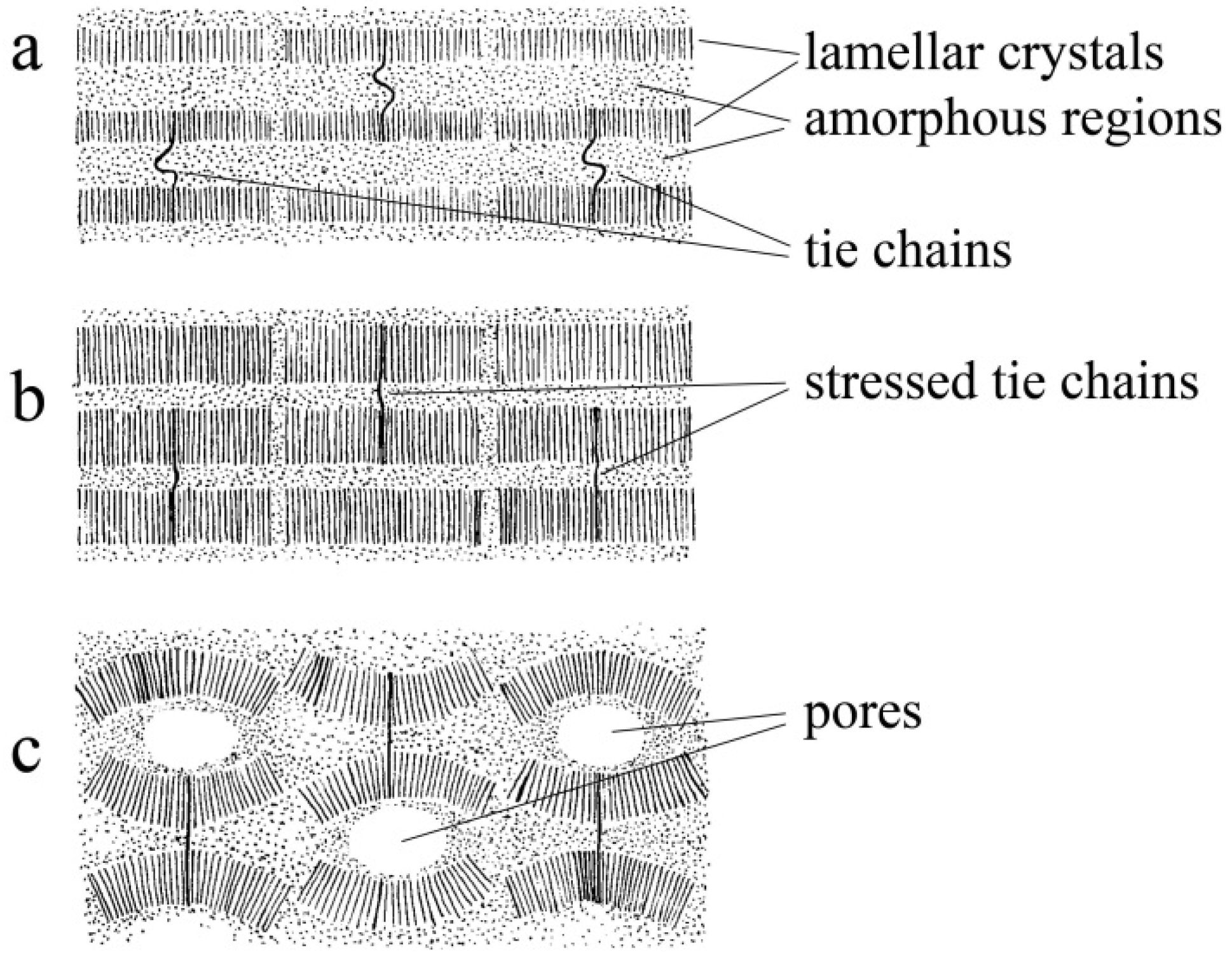
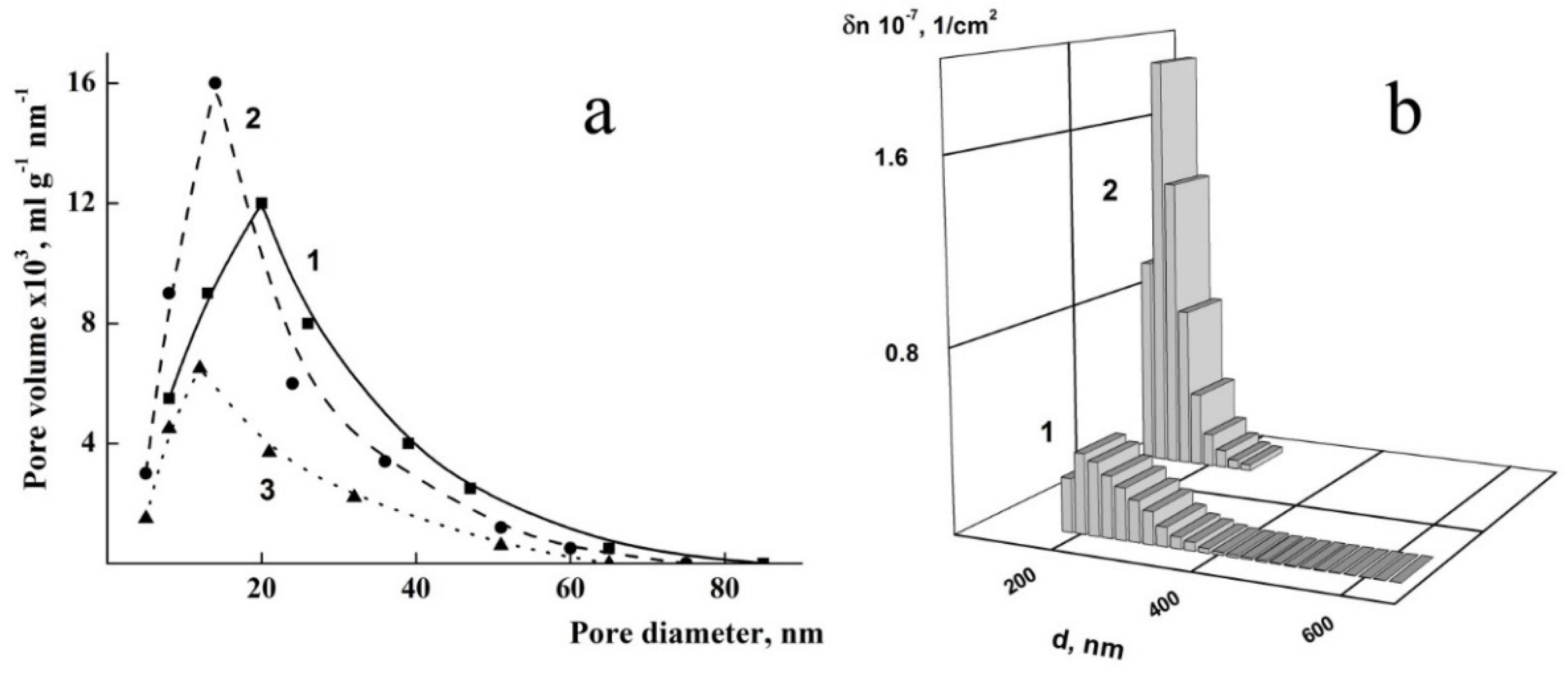
3.1. Characterization of Porous Supports

The process used in this paper for the preparation of microporous films as supports for the composites includes the following stages [34,35]: (i) extrusion of the melt through a flat spinneret, (ii) annealing under isometric conditions, (iii) uniaxial extension of the annealed samples (the stage of pore formation), and (iv) thermal fixation. The conditions of the process are characterized by the orientation and thermal parameters (Table 1) which determine the structure and properties of microporous films.
Flexible-chain thermoplastic crystallizable polymers, such as PE, PP, and PVDF, were chosen for the support preparation according to the mechanism of molecular chain folding and the formation of folded-chain lamellar crystals in the shape of flat plates connected by tie chains in the amorphous regions between lamellae. Due to the melt drawing, the extruded films had the oriented stacked lamellar structure where molecular chains in lamellae are oriented in the melt orientation direction (Figure 1a).
The extruded films were annealed at the temperature near melting point in isometric condition to avoid shrinkage during heating. The annealing led to an increase in the thickness of the lamellae due to the involvement of tie chains in the crystals and, as a result, strong growth in the degree of crystallinity (approximately in 1.5–2 times) was accompanied by a sharp decrease in the number of tie chains (Figure 1b).
Uniaxial extension of the annealed films initiates the appearance of voids as a result of the moving apart of lamellae and the effective pore generation process. It is possible to see that the transparent initial (extruded and annealed) film becomes opaque milky-white during the extension process because of light scattering on the walls of pores (Figure 1c).
After that, the porous structure should be thermally stabilized by keeping the fixed stressed films at elevated temperature to prevent their shrinkage after stress relief.
The porous structure of the supports was characterized by overall porosity (P) (the portion of the film volume occupied by pores) and specific surface (S) measured by sorptometry (Table 2). Note that the value of specific surface for these porous films (the order of several tens of m2/g) is much higher than this value for nonporous “smooth” films of these polymers, which is approximately 10−4 m2/g.
Growth of orientation efforts in the preparation process leads to the growth of the number and sizes of pores, and when overall porosity (P) reaches the percolation threshold value (not less than 23%–25% according to percolation theory [40]) the through flow channels are formed in the film, which acquires permeability for liquids. It is important to note that the data for overall porosity in Table 2 include all types of pores which are formed in the sample, i.e., open to the surface, closed in the volume (the space of interlamellar regions), as well as through channels. It can be seen in Table 2 that PE and PP supports are characterized by the higher values of overall porosity and pore sizes, and consequently permeability, than PVDF films. These results are supported by the data concerning sorptometry (Figure 2a). The higher specific surface of PP supports is related to the larger number of pores (especially small pores). Pore distributions were obtained by filtration porosimetry (Figure 2b). For PVDF films, it was impossible to obtain the full dependence of permeability on pore sizes because of the overly large pressure which should be used in filtration porosimetry in the range of small sizes of pores (which may be dangerous for the mechanical integrity of the film).
Orientation efforts during the preparation process led to the formation of the oriented structure of these porous supports. X-ray scattering investigations evidence that all these films are characterized by a high orientation factor fc equal to 0.91, 0.88, and 0.89 for PE, PP, and PVDF supports, respectively.
One feature of these porous films is their strongly developed relief-like surface (Figure 3) which arises as a result of the release of stress accumulated inside the sample in the uniaxial extension process at the pore formation stage. It was shown [41] that the scale of relief increases with the orientation parameters of the film preparation process. The pictures of atomic force microscopy convincingly demonstrate the pronounced relief character of the supports surfaces (Figure 3). The oriented character of the films structure is clearly seen in the 3D images. By analyzing the profile of the surface relief, it is possible to estimate the depth of the open to surface pores, which reaches the values of 400, 150, and 300 nm for PE (Figure 3a), PP (Figure 3b), and PVDF (Figure 3c) supports, respectively. The values of the arithmetic mean (Ra) and root-mean-square (Rq) surface roughness for the 14 µm × 14 µm scanning matrix are 107.7 and 131.9 nm for PE (Figure 3a), 34.8 and 43.9 nm for PP (Figure 3b), and 83.9 and 102.8 nm for PVDF (Figure 3c) supports. The comparison of these data shows that PP porous films have a lower scale of relief (and consequently they have less deep pores open to the surface) than other ones.
It should be noted that all these supports are poorly water wettable materials. It was observed that roughness of surface grows with increasing orientation parameters, which provides a reduction of contact angle for these samples, i.e., improvement of the wettability by water of their surface. For instance, for the dense PVDF films, the contact angle (θ) is nearly 75°, but for the porous PVDF films with relief surface it falls up to approximately 65–70° at the roughness of 100–120 nm [42]. This result is consistent with the commonly accepted conception concerning the influence of surface relief on the wettability of material [43].
The porous structure of the supports is controlled by the oriented parameters of the preparation process (melt draw ration and degree of uniaxial extension), and the number and sizes of pores may be varied in a wide range of nano- and micro-sizes.

3.2. Electroconducting Polymer Coatings onto Porous Supports

Polymer porous supports were used for the preparation of the composites by the formation of the electrically conductive polymer coatings, i.e., polyaniline and polypyrrole. The conducting layers were obtained by the oxidative polymerization of the monomers directly onto the porous supports. The photographs of the samples are presented in Figure 4. It can be seen that the porous supports (Figure 4a–c) are the opaque milk-white films. The PANI coatings deposited onto the porous support (Figure 4d–f) have a bright emerald, green color which evidences that the conducting form of PANI (i.e., emeraldine salt) was synthesized in this composite. The composites pictures in (Figure 4g–i) demonstrate the formation of homogeneous, defectless black PPy coatings. As a result of the preparation procedures used in this work, the conducting layers of PANI and PPy were deposited on both sides of the film supports.
The morphology of the supports and the composite films was studied using scanning electron microscopy (Figure 5). The SEM picture of the support (Figure 5a) demonstrates its developed relief structure formed by the alternating surface comb-like peaks and cavities between them. The investigations have shown that the character of the composites surfaces is determined by the morphologic structure of the conducting polymer which fully masks the relief of supports. The SEM pictures of the coatings in composites were similar to each other for all supports, and the surface morphology of the composite was determined by the structure of the coating polymer. SEM micrographs of composites containing PANI layers (Figure 5b) show that polyaniline fills the pores and forms a so-called cauliflower structure on the support surface. The composites formed by PPy coatings (Figure 5c) have the inherent PPy globular structure. It can be seen in Figure 5 that the higher content of PPy in the composite compared to PANI (Table 3) provides the formation of more dense and homogeneous coatings, and consequently a lower specific surface. As a result of the coating formation, the specific surface S of the composites is lower than that for the corresponding supports (compare Table 2 and Table 3).

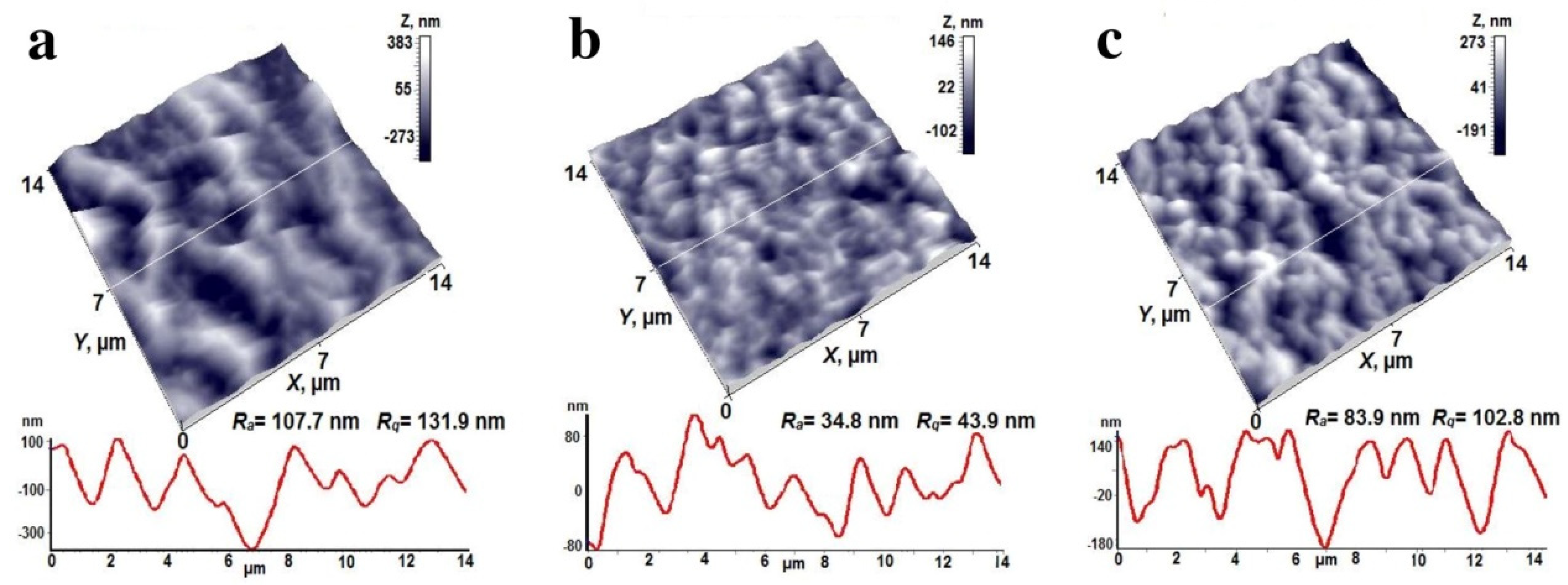
3.3. Properties and Characteristics of the Electroactive Composites

Electric properties of the composites were characterized by σs (along the surface) and σv (between the surfaces of the sample) conductivities (Table 3). The σv conductivity is provided by the conducting component, which is polymerized not only on the support surface, but also on the walls of pores and in the interlamellar regions, which leads to the formation of the space continuous conducting phase in the composites. Note that the support materials are insulators (their conductivity is of the order 10−11–10−18 S/cm), so they do not affect the conductivity of the coatings. The higher conductivity of the composites with PPy component (in comparison with composites containing PANI) is related to the deeper penetration of the monomer in the volume of the supports due to the better wettability of support by pyrrole polymerization media containing methanol as compared with water media, which was used for PANI synthesis, and as a result the composites with PPy contain a greater amount of conducting component and have a higher conductivity (Table 3). The composites applied to PVDF supports are characterized by the lower porosity of these films (Table 2), namely fewer sizes and number of pores (and also through channels), and consequently lower content of conducting component.
The electrical conductivity of the composites is comparable (or higher) with known values for conducting polymer-based hybrid systems. For instance, the composites with PANI layers have conductivities 2 × 10⁻² and 0.5–5.8 S/cm for (PE support)/PANI and (PP support)/PANI, respectively [44,45]; the composites with PPy layers on PE and PP supports in [47,48,49] show conductivity 3.25–4.46 S/cm; (PVDF support)/PANI composites were reported to have conductivity 10−1–10−4 S/cm [46,50].
It was observed that conducting layers improve the water wettability of the composites in comparison with porous supports (Table 4). The measurements by the contact angle technique have shown that conducting layers provide these composites the noticeable decrease of contact angle, which indicates enhanced wettability with the water (Figure 6).
It was established that the wettability of the composites is determined by the surface properties of conducting coating and does not depend on the characteristics of the support (Table 4).
The mechanical properties of the supports and the composites were investigated by the measurements of stress–strain curves, which are presented in Figure 7. It can be seen that the curves have a path typical for oriented polymer systems. Deformational curves for all the samples are similar to each other, and they evidence that the mechanical characteristics of the composites are determined by those of the supports.
The oriented structure of microporous supports ensures the composites’ good deformation and strength properties (Table 5). It is known that PANI and PPy are rigid-chain polymers, and their presence as components in the composites often leads to a lowering of mechanical strength and elasticity. The layers of conducting polymers as rigid components in the composites under study provide a significant increase in elastic modulus, while tensile strength and breaking elongation retain the values of the supports (Table 5). For the composites with PPy, the elongation at break is slightly lower because of the high content of rigid component, but for the composites with PANI, it is a little higher due to healing defects (filling surface pores by PANI). It should be noted that the composites preserve mechanical integrity at deformation up to the break, and their tensile strength and elasticity are maintained at a sufficiently high level for practical application.
The supports and the composites, being oriented systems, reveal the anisotropy of mechanical properties. It is seen in Table 5 that tensile strength values are much higher in the orientation direction than in the perpendicular one, which may be explained by the greater number of strong bridges between lamellae in the orientation direction than between stacks of lamellae. The higher values of elastic modulus for PVDF support at deformation in the perpendicular direction are related to the stronger interactions between lamellae stacks and the details of the crystalline structure of this polymer. The anisotropy of mechanical properties is also illustrated by the relations of values for elongation at break, i.e., elasticity of the samples in two directions. It is possible to notice in Table 5 that the most significant increase for elastic modulus of the composites as compared with supports was observed for the composites containing PPy coating that is related to the high content of the rigid-chain component. Diversities in the elastic modulus ratios in two directions are due to the features of the supermolecular structure of the support polymer material. However, it is possible to see in Table 5 that the composites have a higher elastic modulus than supports, and the composites containing PPy coatings are characterized by the highest moduli because this rigid component fills the porous space of the supports to a greater extent than PANI.
It was established that the formed conducting coatings demonstrate high adhesion to the porous films, and no exfoliation was observed during the mechanical bending of the composites at deformation up to the break. At the same time, the PPy and PANI layers were easily separated from the smooth, dense support. This means that a relief-like surface and porous structure provide the adhesion between the components of the sample. It is shown by IR spectroscopy [42] that there are no chemical interactions between the components. This is evidence that high adhesion between the coatings and support is provided by a highly developed relief-like surface, open to surface pores, and by the formation of a continuous framework of conducting polymer inside the composite that ensures the bonding of conducting coating to the porous support via a mechanism of mechanical adhesion [42,51].
Of particular interest are the PVDF-based composites as new multifunctional film materials which are characterized by the unique combination of porosity and piezoac-tivity. Electric properties of the deposited conducting coatings present the possibility to use them as electrodes for polarization and measurements of piezomodulus of the compo-sites: the value of piezomodulus d31 reached 25 pC/N [41,52,53], which is one the highest values for PVDF film materials. Such composites may be effectively used for application in systems involving the storage and conversion of energy, as electro-acoustic transducers, biosensors, and actuators. It should be noted that the developed approach permits the authors of this work to increase the porosity of PVDF films and to prepare the porous PVDF films containing through flow channels (this has not been achieved by other authors). This sharply expands the application field of these films, and due to their piezoelectric activity, permits their use as filtration membranes with self-cleaning abilities following contamination.

4. Conclusions

In this work, a new approach to prepare composite materials via the formation of electroconductive polymer continuous phase on the surface and in the volume of porous supports is developed. The structure evolution in the preparation process has been investigated. It is demonstrated that the conducting phase of the composites has the homogeneous defectless space-continuous structure, resulting in a high conductivity of the composites in the order 0.8–1.0 S/cm, which considerably exceeds the values published by other authors. The composites are characterized by a balanced combination of mechanical characteristics, namely they have a higher elastic modulus (2000–2100 MPa) than the supports (600–800 MPa), while they are maintaining the elasticity of the support. These composites represent prospective materials for applications as separators (permeable microporous membranes) in electric batteries, especially given their portable small-size version, with separate anode and cathode spaces as well as ion flowing of electrolyte, and the conducting coatings act as contact electrodes. The preparation process developed in this work make it possible to produce ready-to-use smart materials for a wide range of applications, such as gas separation and ion-exchange membranes, electrochemical sensors, as well as “electromagnetic shield” materials which are capable of effectively absorbing electromagnetic radiation over a wide wavelength range.

Author Contributions

G.K.E. contributed to the conceptualization, writing and editing, validation, and evaluation of the data reported in the paper; D.I.G. contributed to the experimental research; I.S.K. contributed to the experimental research and data reconciliation; V.K.L. contributed to the experimental research and evaluation of the results; E.Y.R. contributed to the experimental research; M.E.V. contributed to the experimental research. All authors have read and agreed to the published version of the manuscript.

Funding

The work is supported by the Program of Fundamental Investigations, Ministry of Science and Education of the Russian Federation.

Institutional Review Board Statement

Not applicable.

Informed Consent Statement

Not applicable.

Data Availability Statement

Data sharing is not applicable to this article.

Acknowledgments

Authors would like to thank. G.V.Vaganov and N.N.Saprykina for the aid and support with experimental work.

Conflicts of Interest

The authors declare that they have no conflict of interests.

References

  1. MacDiarmid, A.G. Synthetic metals: A novel role for organic polymers. Synth. Met. 2002, 125, 11–22. [Google Scholar] [CrossRef]
  2. Nalwa, H.S. (Ed.) Handbook of Organic Conductive Molecules and Polymers; John Wiley & Sons: Chichester, UK; New York, NY, USA; Weinheim, Germany; Brisbane, QLD, Australia; Singapore; Toronto, ON, Canada, 1997; Volume 2, 888p. [Google Scholar]
  3. Joo, J.; Lee, J.K.; Baeck, J.S.; Kim, K.H.; Oh, E.J.; Epstein, J. Electrical, magnetic and structural properties of chemically and electrochemically synthesized polypyrrols. Synth. Met. 2001, 117, 45–51. [Google Scholar] [CrossRef]
  4. Wang, L.X.; Li, X.J.; Yang, Y.L. Preparation, properties and applications of polypyrroles. React. Funct. Polym. 2001, 47, 125–139. [Google Scholar] [CrossRef]
  5. Nicolas-Debarnot, D.; Poncin-Epaillard, F. Polyaniline as a new sensitive layer for gas sensor. Anal. Chim. Acta 2003, 475, 1–15. [Google Scholar] [CrossRef]
  6. Bar-Cohen, Y.; Zhang, Q. Electroactive polymer actuators and sensors. MRS Bull. 2008, 33, 173–181. [Google Scholar] [CrossRef] [Green Version]
  7. Janmanee, R.; Chuekachang, S.; Sriwichai, S.; Baba, A.; Phanichphant, S. Functional conducting polymers in the application of SPR biosensors. J. Nanotechnol. 2012, 2012, 620309. [Google Scholar] [CrossRef] [Green Version]
  8. Kaur, G.; Adhikari, R.; Cass, P.; Bown, M.; Gunatillake, P. Electrically conductive polymers and composites for biomedical applications. RSC Adv. 2015, 5, 37553–37567. [Google Scholar] [CrossRef]
  9. Volfkovich, Y.M.; Goroncharovskaya, I.V.; Evseev, A.K.; Sosenkin, V.E.; Goldin, M.M. The effect of electrochemical modification of activated carbons by polypyrrole on their structure characteristics, composition of surface compounds, and adsorption properties. Russ. J. Electrochem. 2017, 53, 1334–1344. [Google Scholar] [CrossRef]
  10. Sun, B.; Wu, T.; Wang, J.; Li, D.; Wang, J.; Gao, Q.; Bhutto, M.A.; El-Hamshary, H.; Al-Deyab, S.S.; Mo, X. Polypyrrole-coated poly(l-lacticacid-co-ε-caprolactone)/silk fibroin nanofibrous membranes promoting neural cell proliferation and differentiation with electrical stimulation. J. Mater. Chem. B 2016, 4, 6670–6679. [Google Scholar] [CrossRef]
  11. Liu, H.; Wang, R.; Chu, H.K.; Sun, D. Design and characterization of a conductive nanostructured polypyrrole-polycaprolactone coated magnesium/PLGA composite for tissue engineering scaffolds. J. Biomed. Mater. Res. A 2015, 103, 2966–2973. [Google Scholar] [CrossRef]
  12. Yuan, L.; Yao, B.; Hu, B.; Huo, K.; Chen, W.; Zhou, J. Polypyrrole-coated paper for flexible solid-state energy storage. Energy Environ. Sci. 2013, 6, 470–476. [Google Scholar] [CrossRef]
  13. Chung, T.C.M. Functional polyolefins for energy applications. Macromolecules 2013, 46, 6671–6698. [Google Scholar] [CrossRef]
  14. Gokhale, A.A.; Lee, I. Recent advances in the fabrication of nanostructured barrier films. J. Nanosci. Nanotechnol. 2014, 14, 2157–2177. [Google Scholar] [CrossRef]
  15. Kim, J.F.; Jung, J.T.; Wang, H.H.; Lee, S.Y.; Moore, T.; Sanguineti, A.; Drioli, E.; Lee, Y.M. Microporous PVDF membranes via thermally induced phase separation (TIPS) and stretching methods. J. Membr. Sci. 2016, 509, 94–104. [Google Scholar] [CrossRef]
  16. Yarysheva, A.I.; Bagrov, D.V.; Rukhlya, E.G.; Yarysheva, L.M.; Volynskii, A.L.; Bakeev, N.F. Features of the delocalized crazing of high-density polyethylene in poly(ethylene oxide) solutions. Polym. Sci. A 2012, 54, 779–786. [Google Scholar] [CrossRef]
  17. Sadeghi, F.; Tabatabaei, S.H.; Ajji, A.; Carreau, P.J. Effect of PVDF characteristics on extruded film morphology and porous membranes feasibility by stretching. J. Polym. Sci. Part B Polym. Phys. 2009, 47, 1219–1229. [Google Scholar] [CrossRef]
  18. Elyashevich, G.K.; Kuryndin, I.S.; Lavrentyev, V.K.; Bobrovsky, A.Y.; Bukošek, V. Porous structure, permeability, and mechanical properties of polyolefin microporous films. Phys. Solid State 2012, 54, 1907–1916. [Google Scholar] [CrossRef]
  19. Elyashevich, G.K.; Kuryndin, I.S.; Lavrentyev, V.K.; Dmitriev, I.Y. Through permeability of polyvinylidene fluoride piezoactive porous films. Polym. Sci. A 2018, 60, 734–741. [Google Scholar] [CrossRef]
  20. Elyashevich, G.K.; Olifirenko, A.S.; Pimenov, A.V. Micro- and nanofiltration membranes on the base of porous polyethylene films. Desalination 2005, 184, 273–279. [Google Scholar] [CrossRef]
  21. Bobrovsky, A.; Shibaev, V.; Elyashevitch, G. Photopatternable fluorescent polymer composites based on stretched porous polyethylene and photopolymerizable liquid crystal mixture. J. Mater. Chem. 2008, 18, 691–695. [Google Scholar] [CrossRef]
  22. Liu, M.; Li, J.; Guo, Z. Polyaniline coated membranes for effective separation of oil in water emulsions. J. Colloid Interface Sci. 2016, 467, 261–270. [Google Scholar] [CrossRef]
  23. Lee, H.S.; Hong, J. Chemical synthesis and characterization of polypyrrole coated on porous membranes and its electrochemical stability. Synth. Met. 2000, 113, 115–119. [Google Scholar] [CrossRef]
  24. Barra, G.M.O.; Matins, R.R.; Kafer, K.A.; Paniago, R.; Vasques, C.T.; Pires, A.T.N. Thermoplastic elastomer/polyaniline blends: Evaluation of mechanical and electromechanical properties. Polym. Test. 2008, 27, 886–892. [Google Scholar] [CrossRef]
  25. Radhakrishnan, S.; Kar, S.B. Role of non-linear processes in conducting polymer blends for piezo-sensors Part 2: Studies on polyaniline/SBS blends. Sens. Actuators A Phys. 2005, 120, 474–481. [Google Scholar] [CrossRef]
  26. Sau, K.P.; Chaki, T.K.; Khastgir, D. The effect of compressive strain and stress on electrical conductivity of conductive rubber composites. Rubber Chem. Technol. 2000, 73, 310–324. [Google Scholar] [CrossRef]
  27. Merlini, C.; Rosa, B.S.; Muller, D.; Ecco, L.G.; Ramoa, S.D.A.S.; Barra, G.M.O. Polypyrrole nanoparticles coated amorphous short silica fibers: Synthesis and characterization. Polym. Test. 2012, 31, 971–977. [Google Scholar] [CrossRef] [Green Version]
  28. Huang, Z.-M.; Zhang, Y.Z.; Kotaki, M.; Ramakrishna, S. A review on polymer nanofibers by electrospinning and their applications in nanocomposites. Compos. Sci. Technol. 2003, 63, 2223–2253. [Google Scholar] [CrossRef]
  29. Chronakis, I.S.; Grapenson, S.; Jakob, A. Conductive polypyrrole nanofibers via electrospinning: Electrical and morphological properties. Polymer 2006, 47, 1597–1603. [Google Scholar] [CrossRef]
  30. Böhnstedt, W. A review of future directions in automotive battery separators. J. Power Sources 2004, 133, 59–66. [Google Scholar] [CrossRef]
  31. Besenhard, J.O. (Ed.) Handbook of Battery Materials; Wiley-VCH: Weinheim, Germany, 1999; 634p. [Google Scholar]
  32. Chakrabarty, B.; Ghoshal, A.K.; Purkait, M.K. Ultrafiltration of stable oil-in-water emulsion by polysulfone membrane. J. Membr. Sci. 2008, 325, 427–437. [Google Scholar] [CrossRef]
  33. Ahmad, A.L.; Majid, M.A.; Ooi, B.S. Functionalized PSf/SiO2 nanocomposite membrane for oil-in-water emulsion separation. Desalination 2011, 268, 266–269. [Google Scholar] [CrossRef]
  34. Elyashevich, G.K.; Rosova, E.Y.; Karpov, E.A. Microporous polyethylene film and method of its production. Russian. Federation Patent 140,936, 15 April 1997. [Google Scholar]
  35. Elyashevich, G.K.; Kuryndin, I.S.; Dmitriev, I.Y.; Lavrentyev, V.K.; Saprykina, N.N.; Bukošek, V. Orientation efforts as regulatory factor of structure formation in permeable porous polyvinylidene fluoride films. Chin. J. Polym. Sci. 2019, 37, 1283–1289. [Google Scholar] [CrossRef]
  36. Gerasimov, D.I.; Kuryndin, I.S.; Lavrentyev, V.K.; Temnov, D.E.; Elyashevich, G.K. Piezoelectric properties of the oriented porous poly(vynilidene) fluoride films. In AIP Conference Proceedings; AIP Publishing: College Park, MD, USA, 2020; Volume 2308, pp. 030001-1–030001-6. [Google Scholar] [CrossRef]
  37. Skotheim, T.A.; Reynolds, J. (Eds.) Conjugated Polymers: Theory, Synthesis, Properties, and Characterization, 3rd ed.; Handbook of Conducting Polymers; CRC Press Taylor & Francis Group: Boca Raton, FL, USA, 2006; 1024p. [Google Scholar]
  38. Kesting, R.E. Synthetic Polymer Membranes. A Structural Perspective, 2nd ed.; John Wiley & Sons: New York, NY, USA; Chichester, UK, 1985; 348p. [Google Scholar]
  39. Hermans, P.H.; Weidinger, A. On the determination of the crystalline fraction of polyethylenes from X-ray diffraction. Macromol. Chem. 1961, 44, 24–36. [Google Scholar] [CrossRef]
  40. Stauffer, D.; Aharony, A. Introduction to Percolation Theory; Taylor and Francis: London, UK, 1994; 181p. [Google Scholar]
  41. Novikov, D.V.; Lavrentyev, V.K.; Elyashevich, G.K.; Bukošek, V. Disorder–Order transition in microporous oriented polyethylene films. Phys. Solid State 2012, 54, 1903–1906. [Google Scholar] [CrossRef]
  42. Elyashevich, G.K.; Kuryndin, I.S.; Rosova, E.Y.; Gerasimov, D.I.; Vylegzhanina, M.E. Piezoactive composite systems based on porous polyvinylidene fluoride films and conducting polymer layers as electrodes. Phys. Complex Syst. 2021, 2, 25–32. [Google Scholar] [CrossRef]
  43. Boinovich, L.B.; Emelyanenko, A.M. Hydrophobic materials and coatings: Principles of design, properties and applications. Russ. Chem. Rev. 2008, 77, 583–600. [Google Scholar] [CrossRef]
  44. Kornberg, A.B.; Thompson, M.R.; Zhu, S. Flexible conductive substrate incorporating a submicrometer co-continuous polyaniline phase within polyethylene by controlled crazing. ACS Appl. Polym. Mater. 2021, 3, 1880–1889. [Google Scholar] [CrossRef]
  45. Yang, J.; Hou, J.; Zhu, W.; Xu, M.; Wan, M. Substituted polyaniline-polypropylene film composites: Preparation and properties. Synth. Met. 1996, 80, 283–289. [Google Scholar] [CrossRef]
  46. Malmonge, L.F.; Lopes, G.d.A.; Langiano, S.d.C.; Malmonge, J.A.; Cordeiro, J.M.M.; Mattoso, L.H.C. A new route to obtain PVDF/PANI conducting blends. Eur. Polym. J. 2006, 42, 3108–3113. [Google Scholar] [CrossRef]
  47. Dispenza, C.; Sabatino, M.A.; Deghiedy, N.; Casaletto, M.P.; Spadaro, G.; Piazza, S.; El-Rehim, H.A.A. In-situ polymerization of polyaniline in radiation functionalized polypropylene films. Polymer 2015, 67, 128–138. [Google Scholar] [CrossRef]
  48. Chang, Y.Z.; Shi, W.H.; Han, G.Y.; Song, H.; Hou, W.J. Fabrication on the flexible supercapacitor based on the polypyrrole deposited on polyethylene/polypropylene non-woven film. Russ. J. Electrochem. 2020, 56, 947–958. [Google Scholar] [CrossRef]
  49. Huang, X.; Yu, Y.-H.; De Llergo, O.L.; Marquez, S.M.; Cheng, Z. Facile polypyrrole thin film coating on polypropylene membrane for efficient solar-driven interfacial water evaporation. RSC Adv. 2017, 7, 9495–9499. [Google Scholar] [CrossRef]
  50. Ray, S.; Easteal, A.J.; Cooney, R.P.; Edmonds, N.R. Structure and properties of melt-processed PVDF/PMMA/polyaniline blends. Mater. Chem. Phys. 2009, 113, 829–838. [Google Scholar] [CrossRef]
  51. Elyashevich, G.K.; Sidorovich, A.V.; Smirnov, M.A.; Kuryndin, I.S.; Bobrova, N.V.; Trchová, M.; Stejskal, J. Thermal and structural stability of composite systems based on polyaniline deposited on porous polyethylene films. Polym. Degrad. Stab. 2006, 91, 2786–2792. [Google Scholar] [CrossRef]
  52. Elyashevich, G.K.; Dmitriev, I.Y.; Rosova, E.Y. Electroconducting polypyrrole coatings as an electrode contact material on porous poly(vinylidene fluoride) piezofilm. Polym. Sci. A 2021, 63, 47–53. [Google Scholar] [CrossRef]
  53. Elyashevich, G.K.; Kuryndin, I.S.; Rosova, E.Y.; Saprykina, N.N. Polymer piezoelements based on porous polyvinylidene fluoride films and contact electrode polyaniline layers. Phys. Solid State 2020, 62, 566–573. [Google Scholar] [CrossRef]
Figure 1. The model of the structure evolution at the porous supports preparation: extruded (a), annealed (b), and porous (c) films.
Coatings 12 00051 g001
Figure 2. Pore sizes distribution in the samples (sorptometry): PE (1), PP (2) and PVDF (3) (a), through pore size distribution (filtration porosimetry): PE (1), PP (2) (b).
Coatings 12 00051 g002
Figure 3. Atomic force 3D images and profiles of relief of PE (a), PP (b) and PVDF porous supports (c).
Coatings 12 00051 g003
Figure 4. Photographs of porous PE (a), PP (b), and PVDF (c) supports; PANI (df) and PPy (gi) coatings onto PE (d,g), PP (e,h), and PVDF (f,i) supports.
Coatings 12 00051 g004
Figure 5. SEM micrographs (surface) of porous support (a), composites (porous support/PANI coating) (b), and (porous support/PPy coating) (c).
Coatings 12 00051 g005
Figure 6. Contact angles for the water-wetted surfaces of porous supports (ac) and composites (d,e): PE (θ1), PP (θ2) and PVDF (θ3) supports; (PP support/PANI) (θ4), and (PP support/PPy) (θ5) composites.
Coatings 12 00051 g006
Figure 7. Stress-strain curves for the supports and the composites based on PE (a), PP (b) and PVDF (c) porous films.
Coatings 12 00051 g007
Table 1. Preparation process conditions of the porous supports.
Process ParametersMaterial of Support
PEPPPVDF
1. Melt draw ratio at extrusion767676
2. Temperature of isometric annealing, °C126170168
3. Total degree of extension, %450200110
4. Temperature of thermal stabilization, °C105130100
Table 2. Porous structure characteristics of the supports.
Porous SupportsThickness, µmP, %S, m2/gG, l/(m2·h atm)
(Ethanol)
The Most Probable Size of Through Channels, nmMaximal Size of Through Channels, nm Number of Through Channels/cm2
PE1152544702006402 × 107
PP21501042601202604 × 107
PVDF2027381.5<6065
Table 3. Characteristics of the composites porous support/electroactive coating.
SampleThickness, μmSpecific Surface, m2/gContent of Conducting Polymer, %σv, S/cmσs, S/cmReferences, σs, S/cm
PE support/PANI11433.83.2 × 10−71.22 × 10⁻² [44]
PP support/PANI21684.76.7 × 10−70.80.46 × 10−2 [45]
PVDF support/PANI20312.15.7 × 10−70.70.5 [46]
PE support/PPy1223421.6 × 10−493.25–4.46 [47]
PP support/PPy2210561.3 × 10−318
PVDF support/PPy20113.01.9 × 10−61.9
Table 4. Contact angle (θ) of the porous supports and the composites.
SamplePEPPPVDF
Porous support70°85°68°
Composite (porous support/PANI)59°59°60°
Composite (porous support/PPy)53°55°56°
Table 5. Mechanical characteristics of the porous supports and the composites *.
SampleTensile Strength, MPaElastic Modulus, MPaElongation at Break, %
PE support150/8700/60040/5
PE support/PANI 135/9850/78045/4
PE support/PPy147/102000/155038/2
PP support149/9820/35078/9
PP support/PANI147/9830/40075/8
PP support/PPy140/92100/91070/8
PVDF support137/29650/138044/4
PVDF support/PANI140/30720/146050/3
PVDF support/PPy140/28730/150042/3
* Data are presented as the mechanical properties in the direction of parallel (nominator) and in perpendicular to orientation direction (denominator).
Publisher’s Note: MDPI stays neutral with regard to jurisdictional claims in published maps and institutional affiliations.

