
Comparative Analysis of Polymer Composites Produced by FFF and PJM 3D Printing and Electrospinning Technologies for Possible Filter Applications


Abstract
:
1. Introduction
2. Materials and Methods
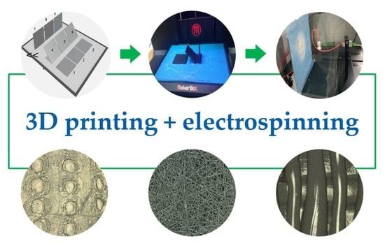
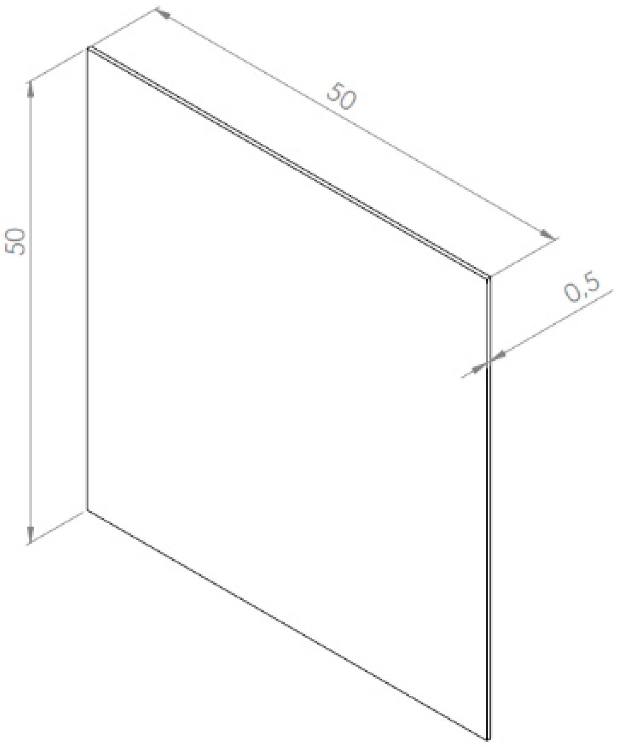
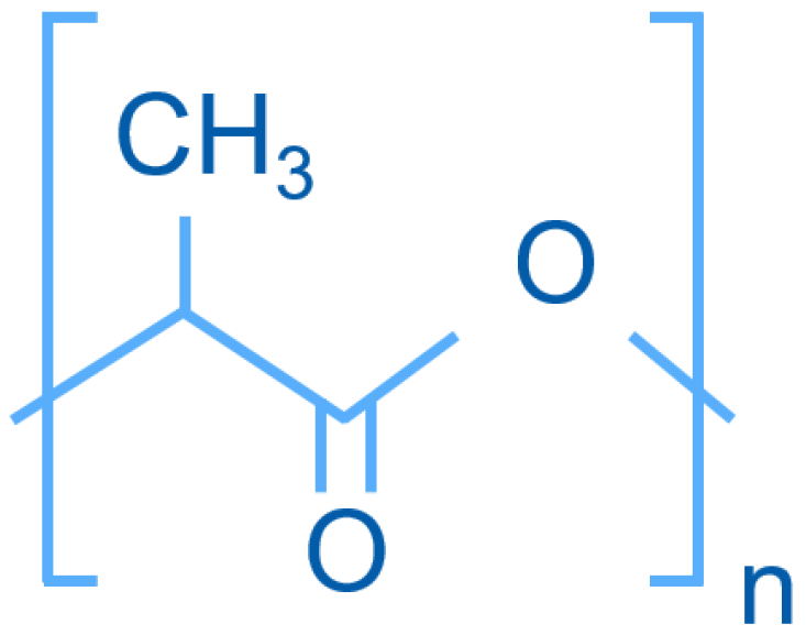
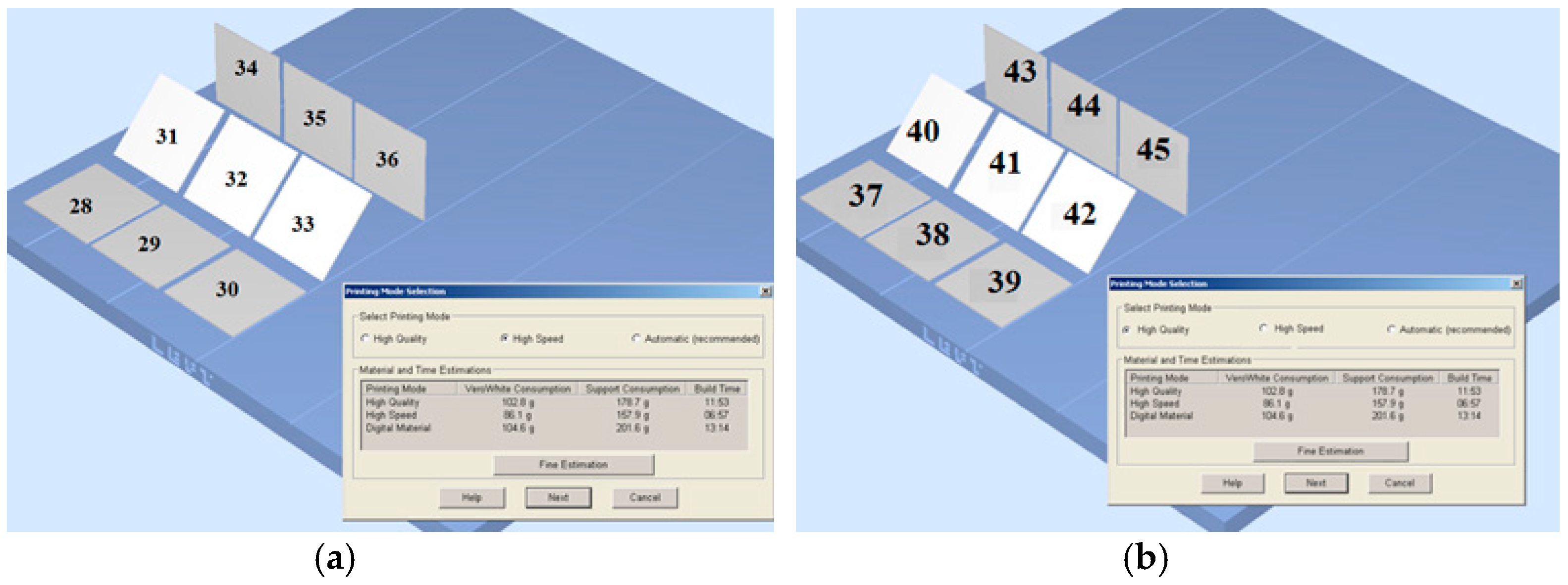
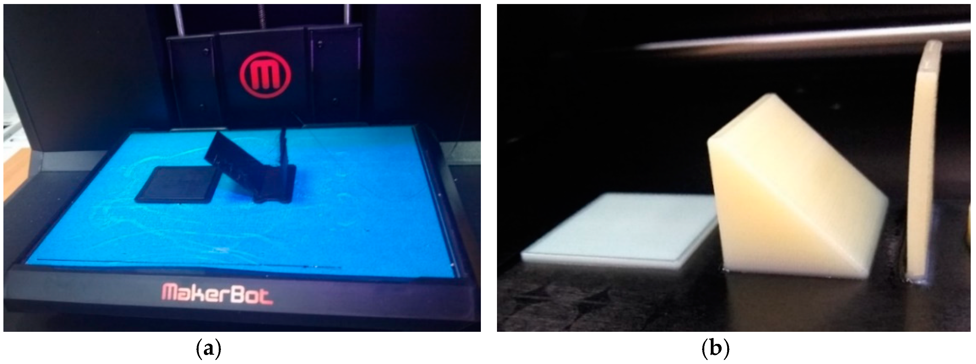
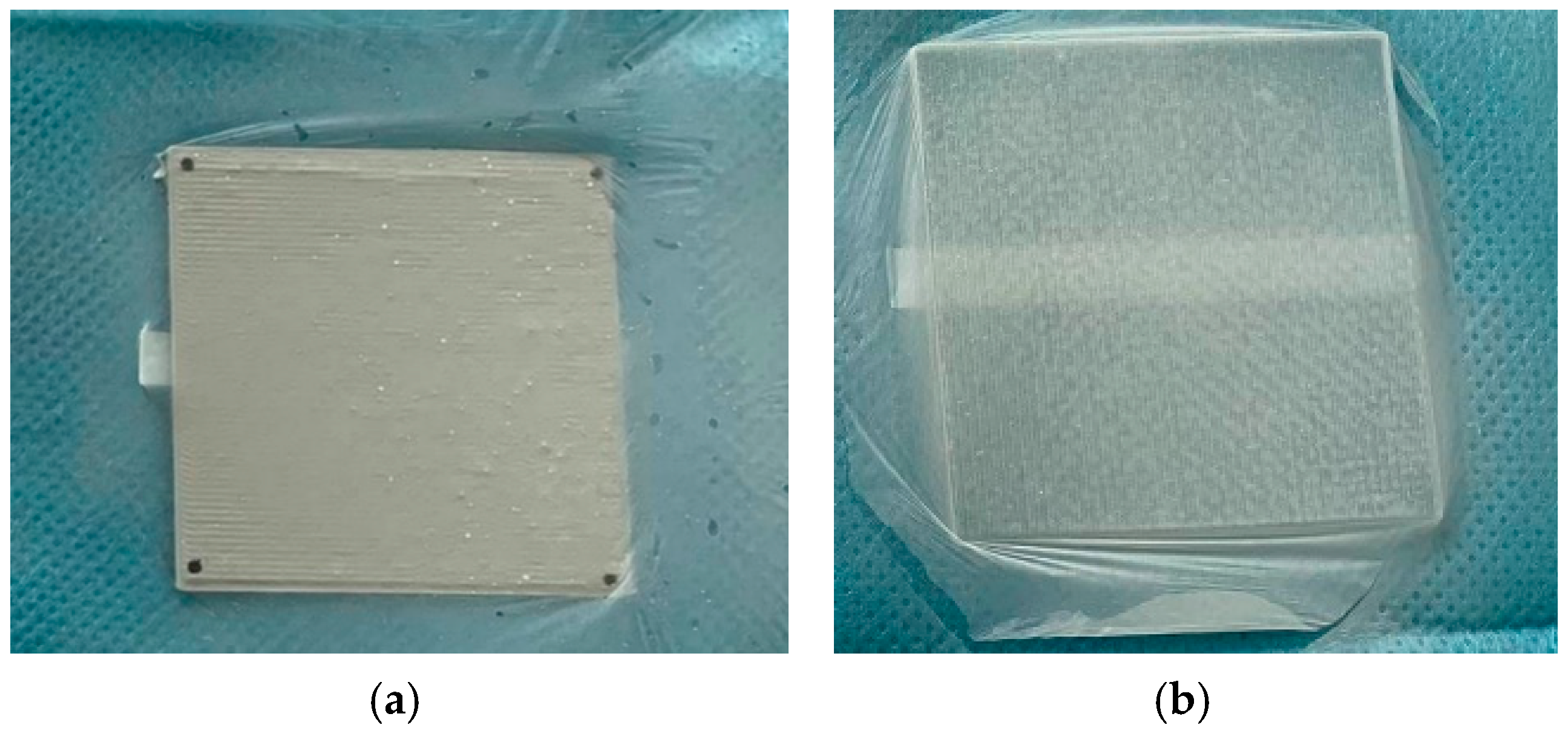
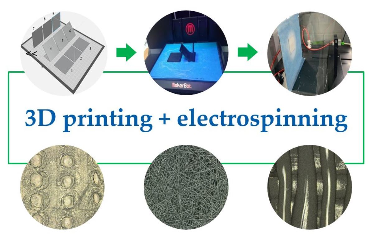
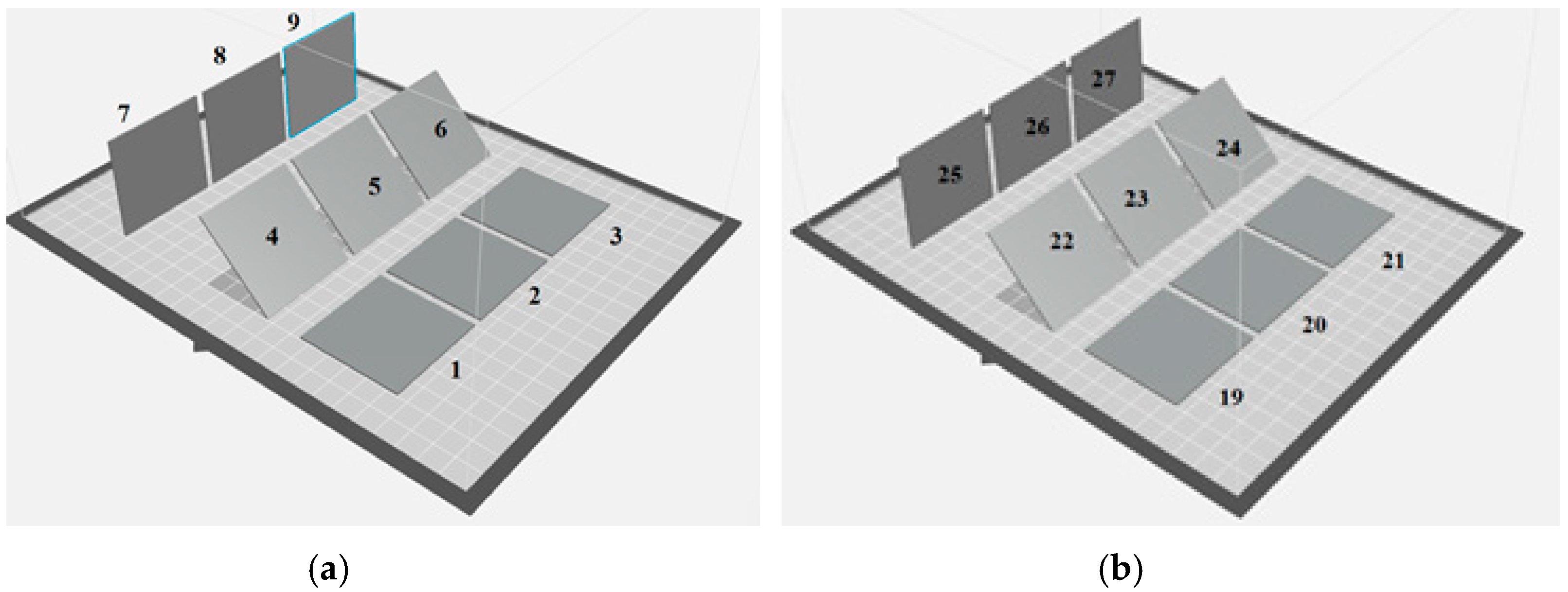
2.1. 3D printing Methods
2.2. Electrospinning
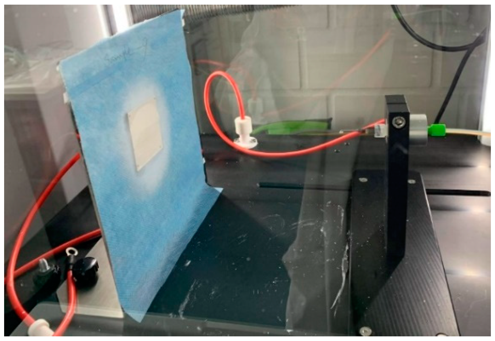
2.3. Research Methods
3. Results
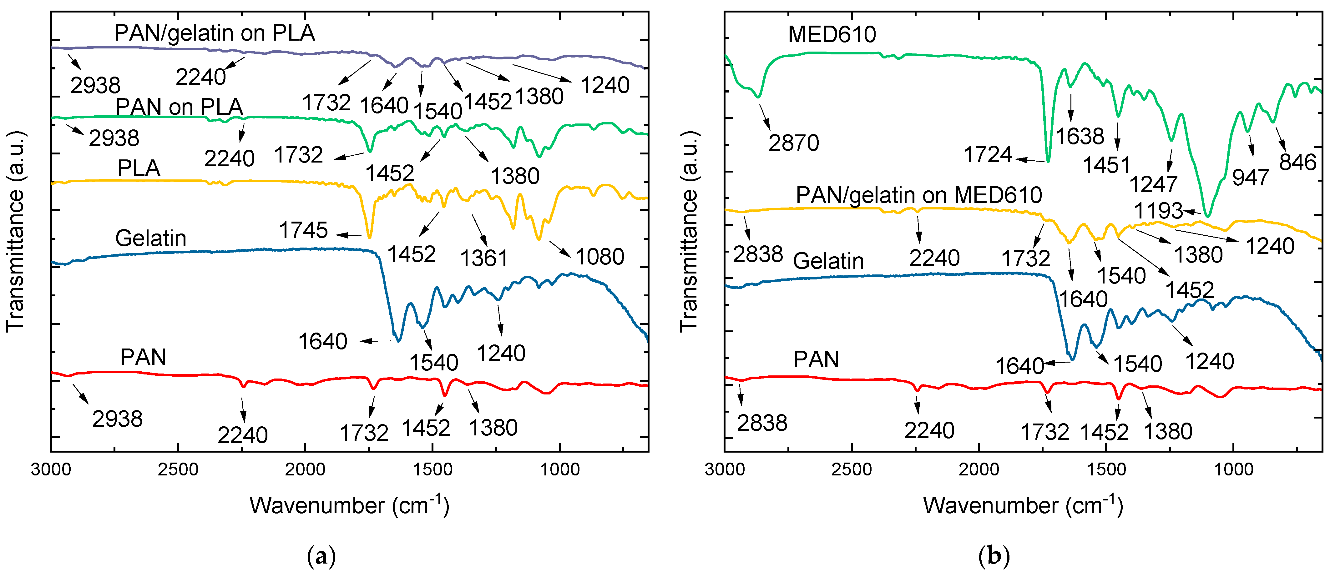
3.1. FTIR Results
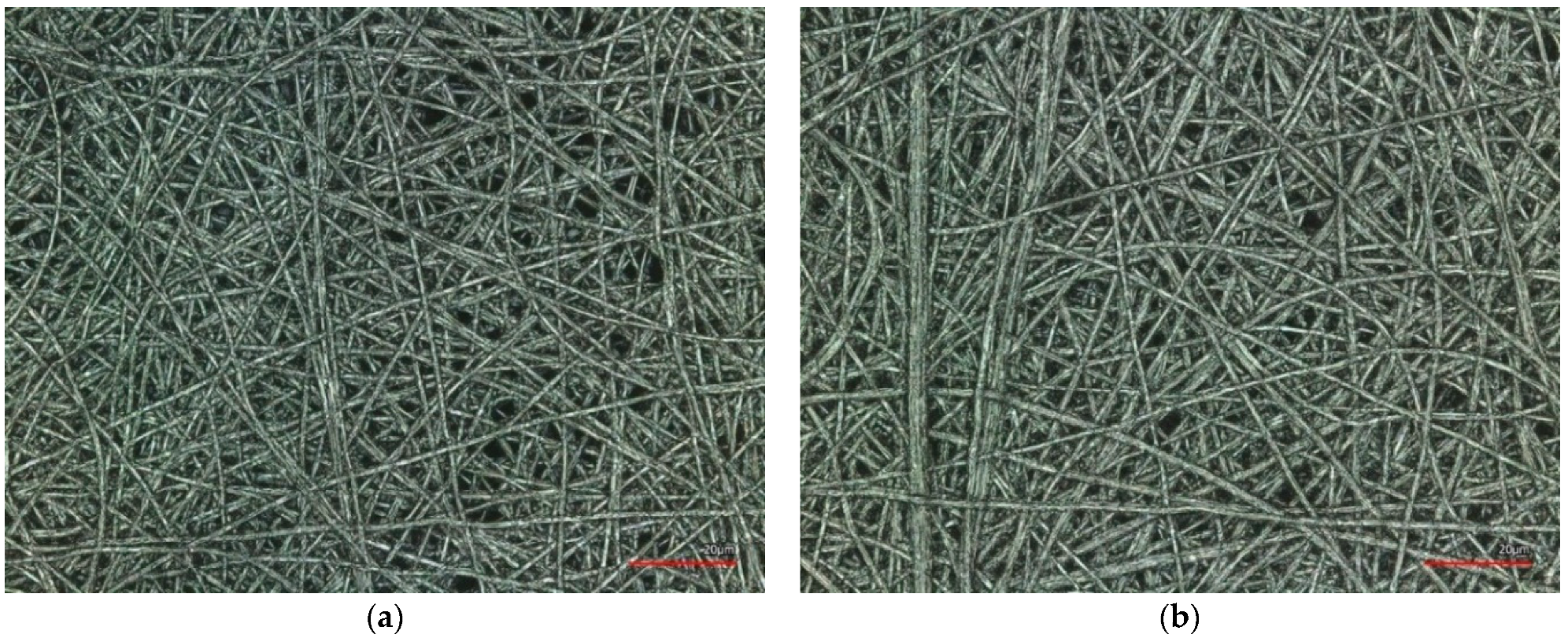
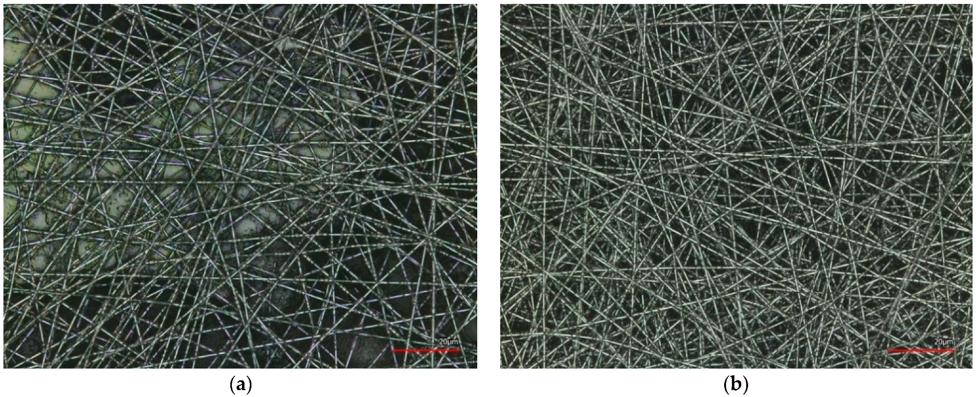
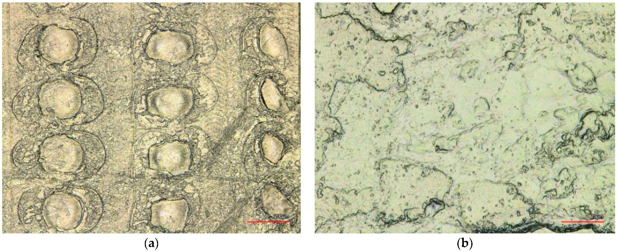
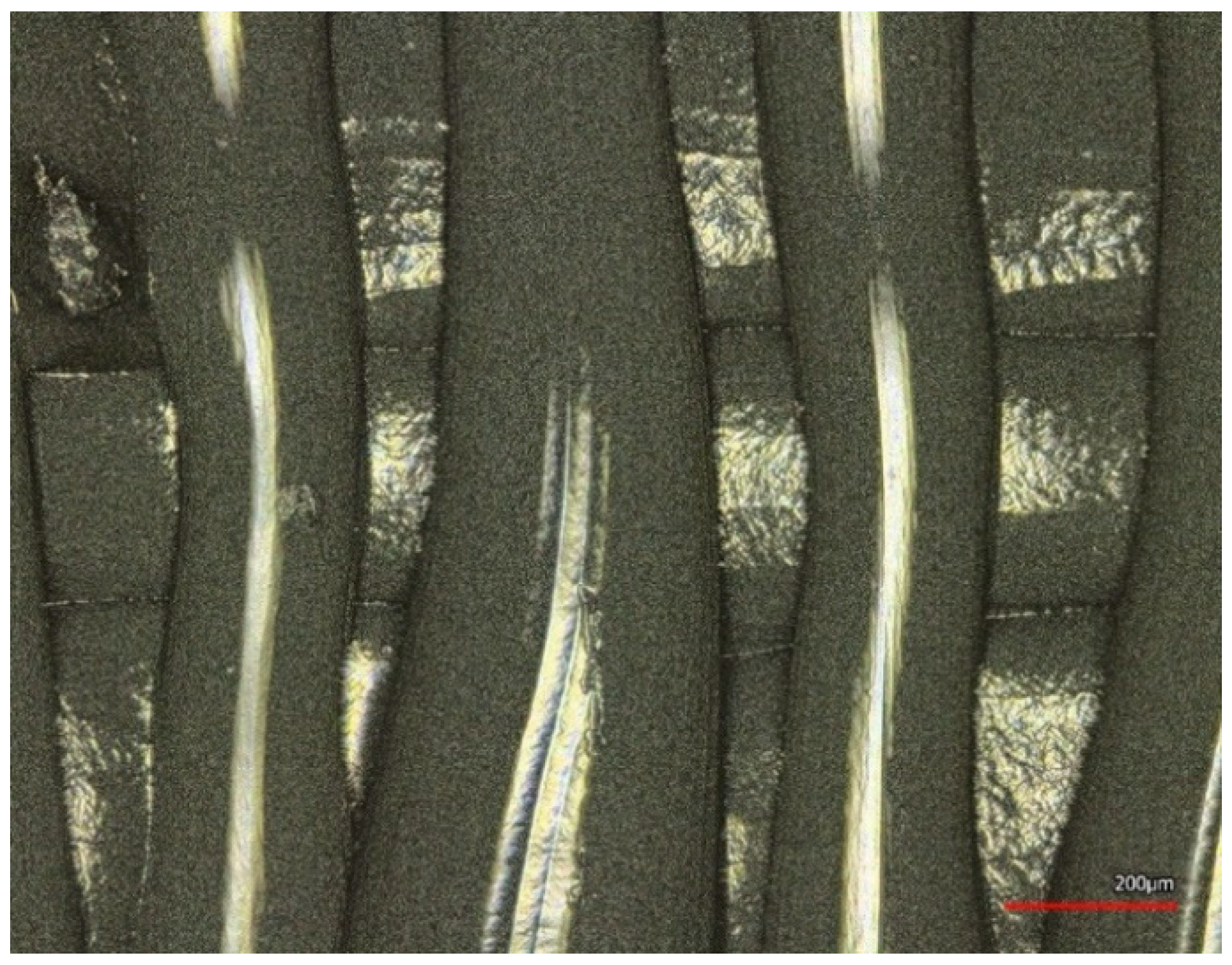
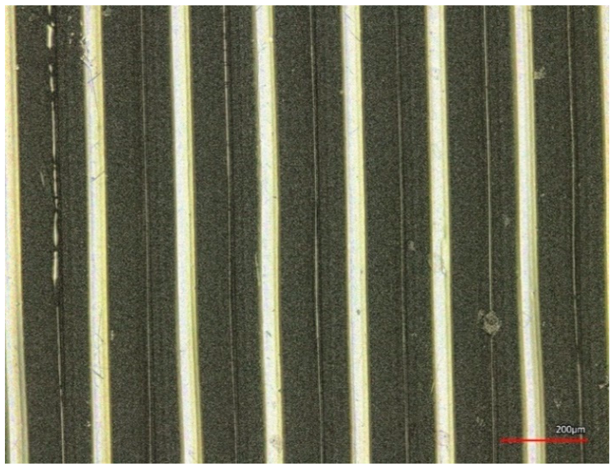
3.2. CLSM Results
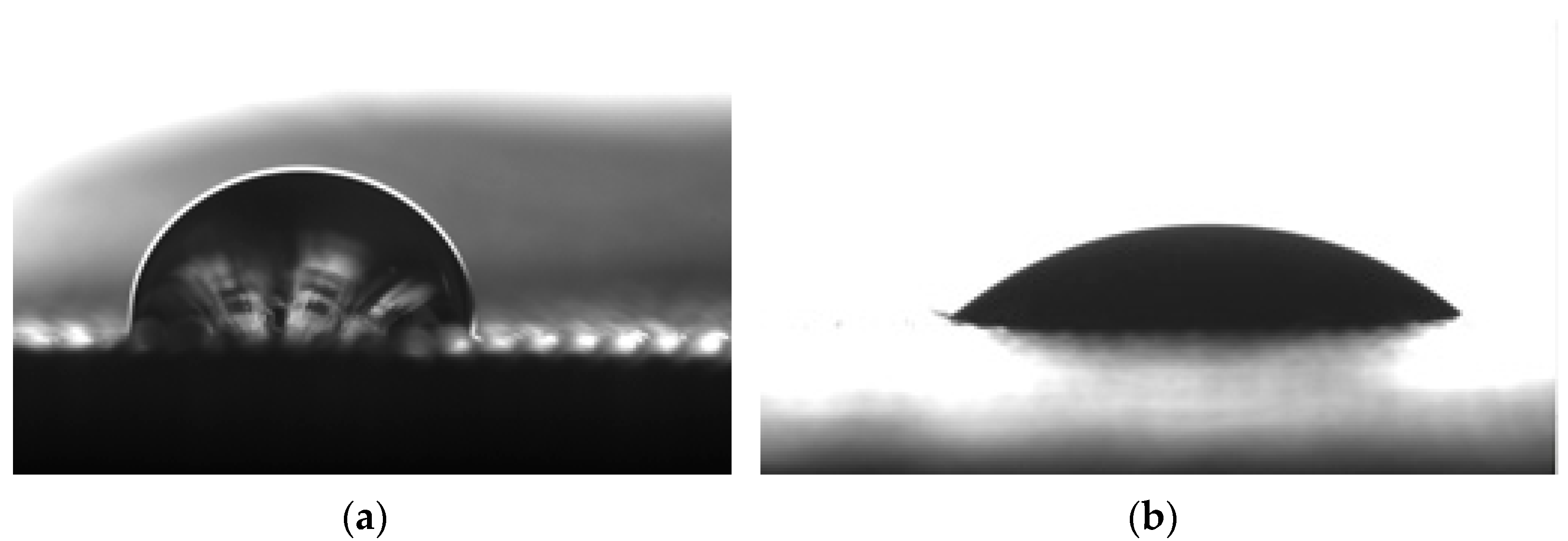
3.3. Contact Angle Results
4. Discussion
5. Conclusions
Author Contributions
Funding
Institutional Review Board Statement
Informed Consent Statement
Data Availability Statement
Acknowledgments
Conflicts of Interest
References
- Adamczak, S.; Zmarzly, P.; Kozior, T.; Gogolewski, D. Analysis of The Dimensional Accuracy of Casting Models Manufactured by Fused Deposition Modeling Technology. In Proceedings of the Engineering Mechanics 2017, Svratka, Czech Republic, 15–18 May 2017. [Google Scholar]
- Kozior, T.; Bochnia, J.; Zmarzły, P.; Gogolewski, D.; Mathia, T.G. Waviness of freeform surface characterizations from austenitic stainless steel (316L) manufactured by 3D printing-selective laser melting (SLM) technology. Materials 2020, 13, 4372. [Google Scholar] [CrossRef]
- Varela, L.; Araújo, A.; Ávila, P.; Castro, H.; Putnik, G. Evaluation of the relation between lean manufacturing, industry 4.0, and sustainability. Sustainability 2019, 11, 1439. [Google Scholar] [CrossRef] [Green Version]
- Kozior, T. The influence of selected selective laser sintering technology process parameters on stress relaxation, Mass of models, and their surface texture quality. 3D Print. Addit. Manuf. 2020, 7, 126–138. [Google Scholar] [CrossRef]
- Madej, M.; Styp-Rekowski, M.; Wieciński, P.; Płociński, T.; Ozimina, D.; Kurzydłowski, K.; Matuszewski, M. Properties of diamond-like carbon coatings deposited on cocrmo alloys. Trans. Famena 2015, 39, 79–88. [Google Scholar]
- Ozimina, D.; Madej, M.; Kałdoński, T. The wear resistance of HVOF sprayed composite coatings. Tribol. Lett. 2011, 41, 103–111. [Google Scholar] [CrossRef]
- Madej, M.; Ozimina, D. Electroless Ni-P-Al2O3 composite coatings. Kov. Mater. 2006, 44, 291–296. [Google Scholar]
- Okolo, C.; Rafique, R.; Iqbal, S.S.; Saharudin, M.S.; Inam, F. Carbon nanotube reinforced high density polyethylene materials for offshore sheathing applications. Molecules 2020, 25, 2960. [Google Scholar] [CrossRef] [PubMed]
- Bochnia, J.; Blasiak, M.; Kozior, T. Tensile strength analysis of thin-walled polymer glass fiber reinforced samples manufactured by 3D printing technology. Polymers 2020, 12, 2783. [Google Scholar] [CrossRef]
- Saharudin, M.S.; Hajnys, J.; Kozior, T.; Gogolewski, D.; Zmarzły, P. Quality of surface texture and mechanical properties of PLA and PA-based material reinforced with carbon fibers manufactured by FDM and CFF 3D printing technologies. Polymers 2021, 13, 1671. [Google Scholar] [CrossRef]
- Mousapour, M.; Salmi, M.; Klemettinen, L.; Partanen, J. Feasibility study of producing multi-metal parts by Fused Filament Fabrication (FFF) technique. J. Manuf. Process. 2021, 67, 438–446. [Google Scholar] [CrossRef]
- Dziegielewski, W.; Kowalczyk, J.; Kulczycki, A.; Madej, M.; Ozimina, D. Tribochemical interactions between carbon nanotubes and ZDDP antiwear additive during tribofilm formation on uncoated and DLC-Coated steel. Materials 2020, 12, 2409. [Google Scholar] [CrossRef]
- Kozior, T.; Kundera, C. Viscoelastic properties of cell structures manufactured using a photo-curable additive technology—PJM. Polymers 2021, 13, 1895. [Google Scholar] [CrossRef]
- Kundera, C.; Martsynkowskyy, V.; Gudkov, S.; Kozior, T. Effect of rheological parameters of elastomeric ring materials on dynamic of face seals. Procedia Eng. 2017, 177, 307–313. [Google Scholar] [CrossRef]
- Kozior, T.; Mamun, A.; Trabelsi, M.; Wortmann, M.; Sabantina, L.; Ehrmann, A. Electrospinning on 3D printed polymers for mechanically stabilized filter composites. Polymers 2019, 11, 2034. [Google Scholar] [CrossRef] [Green Version]
- Kozior, T.; Trabelsi, M.; Mamun, A.; Sabantina, L.; Ehrmann, A. Stabilization of electrospun nanofiber mats used for filters by 3D printing. Polymers 2019, 11, 1618. [Google Scholar] [CrossRef] [PubMed] [Green Version]
- Martens, Y.; Ehrmann, A. Composites of 3D-Printed Polymers and Textile Fabrics. In Proceedings of the IOP Conference Series: Materials Science and Engineering, Xiamen, China, 20–22 October 2017. [Google Scholar]
- Unger, L.; Scheideler, M.; Meyer, P.; Harland, J.; Görzen, A.; Wortmann, M.; Dreyer, A.; Ehrmann, A. Increasing adhesion of 3D printing on textile fabrics by polymer coating. Tekstilec 2018, 61, 265–271. [Google Scholar] [CrossRef]
- Upadhyay, M.; Sivarupan, T.; El Mansori, M. 3D printing for rapid sand casting—A review. J. Manuf. Process. 2017, 29, 211–220. [Google Scholar] [CrossRef] [Green Version]
- Hlinka, J.; Kraus, M.; Hajnys, J.; Pagac, M.; Petru, J.; Brytan, Z.; Tanski, T. Complex corrosion properties of aisi 316L steel prepared by 3D printing technology for possible implant applications. Materials 2020, 13, 1527. [Google Scholar] [CrossRef] [Green Version]
- Budzik, G.; Przeszlowski, L.; Wieczorowski, M.; Rzucidlo, A.; Gapinski, B.; Krolczyk, G. Analysis of 3D printing parameters of gears for hybrid manufacturing. AIP Conf. Proc. 2018, 1960, 140005. [Google Scholar] [CrossRef]
- Kozior, T.; Mamun, A.; Trabelsi, M.; Sabantina, L.; Ehrmann, A. Quality of the surface texture and mechanical properties of FDM printed samples after thermal and chemical treatment. Stroj. Vestn./J. Mech. Eng. 2020, 66, 105–113. [Google Scholar] [CrossRef] [Green Version]
- Chalgham, A.; Ehrmann, A.; Wickenkamp, I. Mechanical properties of fdm printed pla parts before and after thermal treatment. Polymers 2021, 13, 1239. [Google Scholar] [CrossRef] [PubMed]
- Mamun, A.; Blachowicz, T.; Sabantina, L. Electrospun Nanofiber Mats for Filtering Applications—Technology, Structure and Materials. Polymers 2021, 13, 1368. [Google Scholar] [CrossRef] [PubMed]
- Kozior, T.; Bochnia, J. The influence of printing orientation on surface texture parameters in powder bed fusion technology with 316L steel. Micromachines 2020, 11, 639. [Google Scholar] [CrossRef] [PubMed]
- Bochnia, J.; Blasiak, S. Fractional relaxation model of materials obtained with selective laser sintering technology. Rapid Prototyp. J. 2019, 25, 76–86. [Google Scholar] [CrossRef]
- Hanon, M.M.; Marczis, R.; Zsidai, L. Influence of the 3D printing process settings on tensile strength of PLA and HT-PLA. Period. Polytech. Mech. Eng. 2021, 65, 38–46. [Google Scholar] [CrossRef]
- Ehrmann, G.; Ehrmann, A. Pressure orientation-dependent recovery of 3D-printed PLA objects with varying infill degree. Polymers 2021, 13, 1275. [Google Scholar] [CrossRef]
- Ehrmann, G.; Ehrmann, A. Investigation of the shape-memory properties of 3D printed pla structures with different infills. Polymers 2021, 13, 164. [Google Scholar] [CrossRef] [PubMed]
- Kozior, T.; Kundera, C. Surface texture of models manufactured by FDM technology. In Proceedings of the AIP Conference Proceedings, Maharashtra, India, 5–6 July 2018. [Google Scholar]
- Thompson, A.; Maskery, I.; Leach, R.K. X-ray computed tomography for additive manufacturing: A review. Meas. Sci. Technol. 2016, 27, 072001. [Google Scholar] [CrossRef]
- Wortmann, M.; Frese, N.; Sabantina, L.; Petkau, R.; Kinzel, F.; Gölzhäuser, A.; Moritzer, E.; Hüsgen, B.; Ehrmann, A. New polymers for needleless electrospinning from low-toxic solvents. Nanomaterials 2019, 9, 52. [Google Scholar] [CrossRef] [PubMed] [Green Version]
- Sabantina, L.; Klöcker, M.; Wortmann, M.; Mirasol, J.R.; Cordero, T.; Moritzer, E.; Finsterbusch, K.; Ehrmann, A. Stabilization of polyacrylonitrile nanofiber mats obtained by needleless electrospinning using dimethyl sulfoxide as solvent. J. Ind. Text. 2020, 20, 224–239. [Google Scholar] [CrossRef]
- Wehlage, D.; Blattner, H.; Sabantina, L.; Böttjer, R.; Grothe, T.; Rattenholl, A.; Gudermann, F.; Lütkemeyer, D.; Ehrmann, A. Sterilization of pan/gelatine nanofibrous mats for cell growth. Tekstilec 2019, 62, 78–88. [Google Scholar] [CrossRef]
- Wehlage, D.; Blattner, H.; Mamun, A.; Kutzli, I.; Diestelhorst, E.; Rattenholl, A.; Gudermann, F.; Lütkemeyer, D.; Ehrmann, A. Cell growth on electrospun nanofiber mats from polyacrylonitrile (PAN) blends. AIMS Bioeng. 2020, 7, 43–54. [Google Scholar] [CrossRef]
- Trabelsi, M.; Mamun, A.; Klöcker, M.; Sabantina, L. Investigation of metallic nanoparticle distribution in PAN/magnetic nanocomposites fabricated with needleless electrospinning technique. Commun. Dev. Assem. Text. Prod. 2021, 2, 8–17. [Google Scholar] [CrossRef]
- Sabantina, L.; Wehlage, D.; Klöcker, M.; Mamun, A.; Grothe, T.; García-Mateos, F.J.; Rodríguez-Mirasol, J.; Cordero, T.; Finsterbusch, K.; Ehrmann, A. Stabilization of electrospun PAN/gelatin nanofiber mats for carbonization. J. Nanomater. 2018, 2018, 61310. [Google Scholar] [CrossRef] [Green Version]
- Grothe, T.; Sabantina, L.; Klöcker, M.; Junger, I.; Döpke, C.; Ehrmann, A. Wet relaxation of electrospun nanofiber mats. Technologies 2019, 7, 23. [Google Scholar] [CrossRef] [Green Version]
- Fokin, N.; Grothe, T.; Mamun, A.; Trabelsi, M.; Klöcker, M.; Sabantina, L.; Döpke, C.; Blachowicz, T.; Hütten, A.; Ehrmann, A. Magnetic properties of electrospun magnetic nanofiber mats after stabilization and carbonization. Materials 2020, 13, 1552. [Google Scholar] [CrossRef] [Green Version]
- Sabantina, L.; Böttjer, R.; Wehlage, D.; Grothe, T.; Klöcker, M.; García-Mateos, F.J.; Rodríguez-Mirasol, J.; Cordero, T.; Ehrmann, A. Morphological study of stabilization and carbonization of polyacrylonitrile/TiO2 nanofiber mats. J. Eng. Fiber. Fabr. 2019, 14, 1–8. [Google Scholar] [CrossRef]
- Yusof, M.R.; Shamsudin, R.; Zakaria, S.; Hamid, M.A.A.; Yalcinkaya, F.; Abdullah, Y.; Yacob, N. Electron-beam irradiation of the PLLA/CMS/β-TCP composite nanofibers obtained by electrospinning. Polymers 2020, 12, 1593. [Google Scholar] [CrossRef]
- Kozior, T.; Blachowicz, T.; Ehrmann, A. Adhesion of three-dimensional printing on textile fabrics: Inspiration from and for other research areas. J. Eng. Fiber. Fabr. 2020, 15, 1–6. [Google Scholar] [CrossRef] [Green Version]
- Greiner, A.; Wendorff, J.H. Electrospinning: A fascinating method for the preparation of ultrathin fibers. Angew. Chemie Int. Ed. 2007, 46, 5670–5703. [Google Scholar] [CrossRef] [PubMed]
- Makerbot FDM Technology. Available online: https://www.makerbot.com/3d-printers/method/tech-specs/ (accessed on 27 November 2021).
- Stratasys Biocompatible Clear MED610-Sheet Data. Available online: https://www.sys-uk.com/wp-content/uploads/2016/01/MSDS-Clear-Bio-Compatible-MED610-English-US-1.pdf (accessed on 27 November 2021).
- ISO 10993. Biological evaluation of medical devices. In Biological Evaluation of Medical Devices; ISO: Geneva, Switzerland, 2009. [Google Scholar]
- GTMDB05 Biological Reactivity Tests, In Vivo. In Phyllanthin, United States Pharmacopeia; USP: Rockville, MA, USA, 2018.
- PLA Structural Formula. Available online: https://omnexus.specialchem.com/selection-guide/polylactide-pla-bioplastic (accessed on 27 November 2021).
- Molnár, K.; Szolnoki, B.; Toldy, A.; Vas, L.M. Thermochemical stabilization and analysis of continuously electrospun nanofibers. J. Therm. Anal. Calorim. 2014, 117, 1123–1135. [Google Scholar] [CrossRef]
- Al-Saidi, G.S.; Al-Alawi, A.; Rahman, M.S.; Guizani, N. Fourier transform infrared (FTIR) spectroscopic study of extracted gelatin from shaari (Lithrinus microdon) skin: Effects of extraction conditions. Int. Food Res. J. 2012, 19, 1167–1173. [Google Scholar]
- Chieng, B.W.; Ibrahim, N.A.; Yunus, W.M.Z.W.; Hussein, M.Z.; Then, Y.Y.; Loo, Y.Y. Effects of graphene nanoplatelets and reduced graphene oxide on poly(lactic acid) and plasticized poly(lactic acid): A comparative study. Polymers 2014, 6, 2232–2246. [Google Scholar] [CrossRef] [Green Version]
- Kozior, T.; Döpke, C.; Grimmelsmann, N.; Juhász Junger, I.; Ehrmann, A. Influence of fabric pretreatment on adhesion of three-dimensional printed material on textile substrates. Adv. Mech. Eng. 2018, 10, 1–8. [Google Scholar] [CrossRef] [Green Version]
- Sato, S.; Swihart, M.T. Propionic-acid-terminated silicon nanoparticles: Synthesis and optical characterization. Chem. Mater. 2006, 18, 4083–4088. [Google Scholar] [CrossRef]
- Stratasys. PolyJet 3D Printers Systems and Materials Overview; Stratasys: Rehovot, Israel, 2018. [Google Scholar]
- Korger, M.; Bergschneider, J.; Lutz, M.; Mahltig, B.; Finsterbusch, K.; Rabe, M. Possible applications of 3D printing technology on textile substrates. IOP Conf. Ser. Mater. Sci. Eng. 2016, 141, 01201. [Google Scholar] [CrossRef] [Green Version]


| Information on Ingredients | ||
|---|---|---|
| CAS# | Component | Percent (%) |
| 5888-33-5 | Isobornyl acrylate | 15–30 |
| Proprietary | Acrylic monomer | 15–30 |
| Proprietary | Urethane acrylate | 10–30 |
| Proprietary | Acrylic monomer | 5–10; 10–15 |
| Proprietary | Epoxy acrylate | 5–10; 10–15 |
| Proprietary | Acrylate oligomer | 5–10; 10–15 |
| Proprietary | Photoinitiator | 0.1–1; 1–2 |
| 3D Printed Sample No. | 3D Material | Nanofiber Mats |
|---|---|---|
| 1–6 | PLA | PAN 13% + DMSO 87% |
| 7–18 | PLA | PAN 13% + gelatin 8% + DMSO 79% |
| 19–27 | PLA | PAN 13% + gelatin 8% + DMSO 79% |
| 28–36 | MED610 | PAN 13% + gelatin 8% + DMSO 79% |
| 37–45 | MED610 | PAN 13% + gelatin 8% + DMSO 79% |
| Polymers | FTIR Spectra | Reference |
|---|---|---|
| Gelatin |
| [37,49,50] |
| PLA |
| [51] |
| PAN |
| [52] |
| MED610 |
| [53,54] |
| Calculated Feature | Image in Print Direction | Image Perpendicular to Print Direction |
|---|---|---|
| Mean values and standard deviation of contact angle (°) | 86.8 (±3.4) | 62.7 (±2.8) |
| Calculated Feature | Image in Print Direction | Image Perpendicular to Print Direction |
|---|---|---|
| Mean values and standard deviation of contact angle (°) | 54.7 (±5.5) | 45.2 (±4.0) |
Publisher’s Note: MDPI stays neutral with regard to jurisdictional claims in published maps and institutional affiliations. |
© 2022 by the authors. Licensee MDPI, Basel, Switzerland. This article is an open access article distributed under the terms and conditions of the Creative Commons Attribution (CC BY) license (https://creativecommons.org/licenses/by/4.0/).
Share and Cite
Kozior, T.; Mamun, A.; Trabelsi, M.; Sabantina, L. Comparative Analysis of Polymer Composites Produced by FFF and PJM 3D Printing and Electrospinning Technologies for Possible Filter Applications. Coatings 2022, 12, 48. https://doi.org/10.3390/coatings12010048
Kozior T, Mamun A, Trabelsi M, Sabantina L. Comparative Analysis of Polymer Composites Produced by FFF and PJM 3D Printing and Electrospinning Technologies for Possible Filter Applications. Coatings. 2022; 12(1):48. https://doi.org/10.3390/coatings12010048
Chicago/Turabian StyleKozior, Tomasz, Al Mamun, Marah Trabelsi, and Lilia Sabantina. 2022. "Comparative Analysis of Polymer Composites Produced by FFF and PJM 3D Printing and Electrospinning Technologies for Possible Filter Applications" Coatings 12, no. 1: 48. https://doi.org/10.3390/coatings12010048
APA StyleKozior, T., Mamun, A., Trabelsi, M., & Sabantina, L. (2022). Comparative Analysis of Polymer Composites Produced by FFF and PJM 3D Printing and Electrospinning Technologies for Possible Filter Applications. Coatings, 12(1), 48. https://doi.org/10.3390/coatings12010048