Article

Microstructure and Wear Resistance of a Cr7C3 Reinforced Ni3Al Composite Coating Prepared by Laser Cladding

1
School of Materials Science and Engineering, Hebei University of Technology, Tianjin 300130, China
2
Welding Institute, Central Iron and Steel Research Institute, Beijing 100081, China
3
National United Engineering Laboratory for Advanced Bearing Tribology, Henan University of Science and Technology, Luoyang 471003, China
4
Department of Mechanical Engineering, Tsinghua University, Beijing 100084, China
*
Authors to whom correspondence should be addressed.
Coatings 2022, 12(1), 105; https://doi.org/10.3390/coatings12010105
Submission received: 2 December 2021 / Revised: 9 January 2022 / Accepted: 13 January 2022 / Published: 17 January 2022

Abstract

:
Using Cr7C3/Ni3Al alloyed powder and Cr3C2/Ni3Al mixed powder, laser cladding was carried out to prepare a Cr7C3 reinforced Ni3Al composite cladding layer. The microstructure and tribological properties of the cladding materials were investigated by X-ray diffraction (XRD), scanning electron microscopy (SEM), energy dispersive spectroscopy (EDS), transmission electron microscopy (TEM), and wear tests. The results indicate that the microstructure of the Cr7C3/Ni3Al alloyed powder cladding layer contains mainly Ni3Al, NiAl, and in situ-formed Cr7C3, whereas Cr3C2 occurs in the Cr3C2/Ni3Al mixed powder cladding layer. The friction coefficient and wear loss of the alloyed powder cladding layer are about 0.1 and 0.75 mg, respectively, which are less than those of the mixed powder cladding layer (0.12 and 0.8 mg). Moreover, the alloyed powder cladding layer is much friendlier to its counterpart. The counterpart’s loss weight of the alloyed powder cladding layer decreases 42.2% than the mixed powder cladding layer. The reason can be attributed to the homogeneous distribution of fine in situ-formed Cr7C3 in the alloyed powder cladding materials, which can effectively separate the friction pair, improving the wear resistance of the cladding materials.

1. Introduction

As one of the intermetallic compounds, Ni3Al has many excellent characteristics, such as low density, a high melting point, high temperature oxidation resistance, excellent creep resistance, and outstanding high temperature wear resistance [1,2,3,4]. Furthermore, it has a special abnormal phenomenon, where its yield strength increases with temperature due to its long-range ordered crystal structure of L12 type. Therefore, the Ni3Al alloy is expected to be applicable as a high-temperature wear-resistant material [5,6].
However, the wear resistance of monolithic Ni3Al intermetallic compounds is usually inadequate under the most extreme conditions of severe sliding, impact wear, and abrasive wear [7,8]. Early studies have shown that the high temperature strength and hardness of Ni3Al alloy can be significantly increased by adding Cr3C2 particles, which have the advantages of high hardness, high-temperature stability, excellent high-temperature wear resistance, high compatibility, and wettability with the Ni3Al matrix [9,10,11,12]. Fu et al. [13] prepared a Cr3C2/Ni3Al composite material using hot isostatic pressing technology, and studied the influence of different chromium carbide contents on the wear resistance of the composite. It was found that a certain content of chromium carbide can effectively improve the wear resistance of the material. Gong et al. [14] compared the wear resistance of the Cr3C2/Ni3Al composite material with the monolithic Ni3Al alloy and the gray cast iron, and found that the wear resistance of the composite material is far better than that of single-phase Ni3Al alloy and the gray cast iron. Additionally, it was also found that the wear resistance of the composite material prepared by laser cladding process is superior to that of materials prepared via other preparation processes. Luo et al. [15] compared the wear resistance of Cr3C2/Ni3Al composite coating and the Stellite 12 alloy at room temperature. The results revealed that the wear resistance of the Cr3C2/Ni3Al composite coating is much higher than that of the Stellite 12 alloy, mainly due to the presence of a uniformly distributed hard phase on a highly work-hardened intermetallic matrix in the composite coating. In general, chromium carbide are promising candidates for further improving the tribological properties of Ni3Al alloy [16].
Laser cladding is a complex process combining physics, chemistry, and metallurgy [17,18]. Laser irradiation causes the cladding powders to melt and solidify rapidly on the matrix surface. It forms a fine-grained and tough coating on the substrate surface, and the coating has a dense structure and good metallurgy bonding with the substrate materials [19,20]. Compared with other surface strengthening technologies, laser cladding is an efficient and clean surface modification technology [21].
However, there are only a few reports Cr3C2/Ni3Al composites prepared by laser cladding. In one example, Chen et al. [22] prepared a Cr3C2/Ni3Al composite coating by laser cladding, and studied the microstructure and wear resistance of the coating. The Cr3C2/Ni3Al composite coating thus prepared was found to have good wear resistance. However, the distribution of the reinforcing phase was not uniform in the cladding layer prepared from mixed powders of Ni3Al and Cr3C2. This will greatly influence the wear resistance of the cladding layer. Therefore, in this study, we sought to optimize the distribution uniformity of the strengthening phase in the cladding layer, via a new type of design based on the use of alloyed powders, and the alloyed powders were prepared using vacuum melting gas atomization technology. The microstructure and properties of the Cr7C3/Ni3Al alloyed powder cladding layer and the Cr3C2/Ni3Al mixed powder cladding layer prepared by the same process were then studied.

2. Experimental Materials and Methods

2.1. Composite Powders

Previous studies have shown that addition of about 0.02 wt.% boron plays an important role in increasing the toughness of Ni3Al intermetallic compounds [23]. Additionally, the ratio of Cr and C should be strictly controlled because the Cr atoms will only partly be dissolved into the Ni3Al in the smelting process, so it is necessary to ensure that the actual amount of added Cr is slightly higher than the target amount to be finally dissolved. At the same time, according to the Ni-Al phase diagram in Figure 1, only when the Al content is less than 25 at.% will the Ni3Al be more easily generated [24,25]. Aluminum blocks, chromium blocks, nickel powders, carbon powders, and boron powders (CISRI, Beijing, China), applied as raw materials for powder atomization, were melted in a vacuum furnace at 1900~2000 °C for 1 h, and then atomized into powder. In addition, the atomization pressure also has important effects on powder morphology, fluidity and particle size distribution. Higher atomization pressure leads to a fine powder particle size, which is not suitable for laser cladding; lower atomization pressure will lead to poor sphericity of the cladding powder, which is not conducive to attaining powder with reasonable fluidity. Therefore, the atomization pressure of 2.9–3.2 MPa was selected for powder preparation [26].

2.2. Preparation of Cladding Layer

42CrMo alloyed steel was used as the substrate material. The Cr7C3/Ni3Al alloyed powder (denoted as the alloyed powder) was prepared using the vacuum melting gas atomization technique. For comparison, the Cr3C2/Ni3Al mixed powder (denoted as the mixed powder) was produced by mechanically mixing 25 wt.% Cr3C2 powder (CISRI, Beijing, China) and 75 wt.% Ni3Al powder (The Chalmers University of Technology, Göteborg, Sweden) in this work. The compositions of the substrate material, alloyed powder, and mixed powder are given in Table 1. The particle size of the laser cladding powders was in a range of 45~125 μm. The laser cladding equipment used a YLS-6000 fiber laser (IPG Photonic, Oxford, MA, USA) with a rectangular spot of 5 mm × 2 mm and a focal length of 300 mm. The applied powders were fully dried at 100 °C for 30 min. Then, 400 # SiC sandpaper was used to polish the surface of the 42CrMo alloy steel. Grease and other harmful substances on the surface of the 42CrMo alloy steel pieces were removed by acetone. In the laser cladding process, we used laser coaxial-powder feeding technology, with a laser power of 2.0 kW. Other process parameters were set as follows: scanning speed, 0.18 m/min; DPSF-2 semi-automatic powder feeding device, powder feeding capacity, 1.05 kg/h; argon (purity > 99.9%), as a powder carrier, with a flow rate of protective gas of 15 L/min and a flow rate of powder gas of 5 L/min.

2.3. Microstructure Characterization and Wear Test

Phase analysis of alloyed powder and cladding layer was carried out using a Bruker D8 ADVANCE X-ray diffractometer (XRD, BRUKER, Karlsruhe, Germany) with a scanning speed of 2°/min. The microstructure and phase composition of the cladding layers were analyzed using Zeiss high-resolution field emission scanning electron microscopy (SEM, ZEISS, Jena, Germany), energy dispersive spectroscopy (EDS, ZEISS, Jena, Germany), and high-resolution transmission electron microscopy (JEM-2010, JEOL, Tokyo, Japan). The hardness distribution from the top of the cladding layer to the substrate material was measured with an FM300 microhardness tester (F-T, Tokyo, Japan). A testing load of 100 g was selected, the load retention time was l0 s, and the spacing was 100 μm. Five points were randomly selected on the cladding layer to calculate the average microhardness. A multifunctional friction and wear testing machine (UMT, BRUKER, Madison, MA, USA) was used to test the friction and wear performance. Vermicular graphite cast iron was chosen as the comparison material due to its excellent tribological properties. In the wear test, a cladding sample in the form of a pin with a size of Ø3 mm was used. Gray cast iron was used as a disk material because it has been often used as a counterpart of the piston ring components in engines, as cylinder lines, and as other high-temperature wear parts. The size of the disk was Ø24 mm [27]. Friction and wear test conditions were as follows: dry friction and wear, load of 30 N, rotation speed of 200 r/min, rotation radius of 7 mm, testing time of 60 min, and room temperature. In order to ensure the accuracy of the experimental data, the pin and disk were cleaned by exposure to ultrasonic waves in acetone before and after the test. Then, the weights before and after the wear (m1 and m2, respectively) were valued using a high-precision analytical balance. The wearing quantity Δm = m1 − m2. Thereafter, the counterpart disk was scanned by a 3D white light interferometer. The morphology of the worn surface was observed using a high-resolution field emission scanning electron microscope (Zeiss).

3. Results

3.1. Micro-Analysis on Alloyed Powders

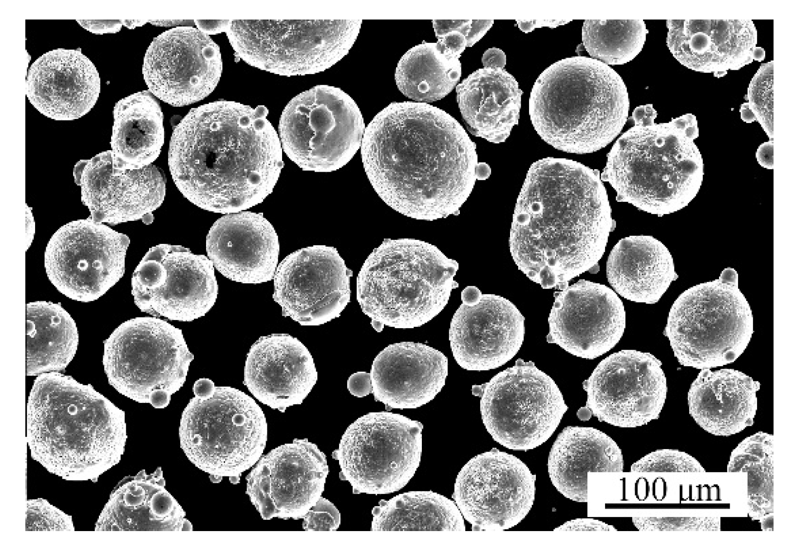
In the process of coaxial powder feeding laser cladding, the powder properties, such as powder fluidity, morphology, and particle size distribution, have an important influence on the quality and performance of the cladding layer [28]. Therefore, the properties of the alloyed powder were first investigated. Figure 2 shows a relatively high sphericity of the alloyed powder shown by scanning electron microscopy. In addition, the morphology of the powders was statistically analyzed via scanning electron microscopy. The results indicate that the sphericity of the composite powders reached 94.2%. The particle size of the composite powder was tested by measured by laser particle size testing, and the results are shown in Figure 3. It can be seen that the particles are mostly distributed in a size range of 45~125 μm. The D50 values are also relatively uniform at about 78.413 μm, following a normal distribution. Particle size obviously affects the convergence point of powder flow and the focal length. The concentration of the convergence point under the same focal length will be higher if the powder is more concentrated, which will in turn increase its utilization rate.
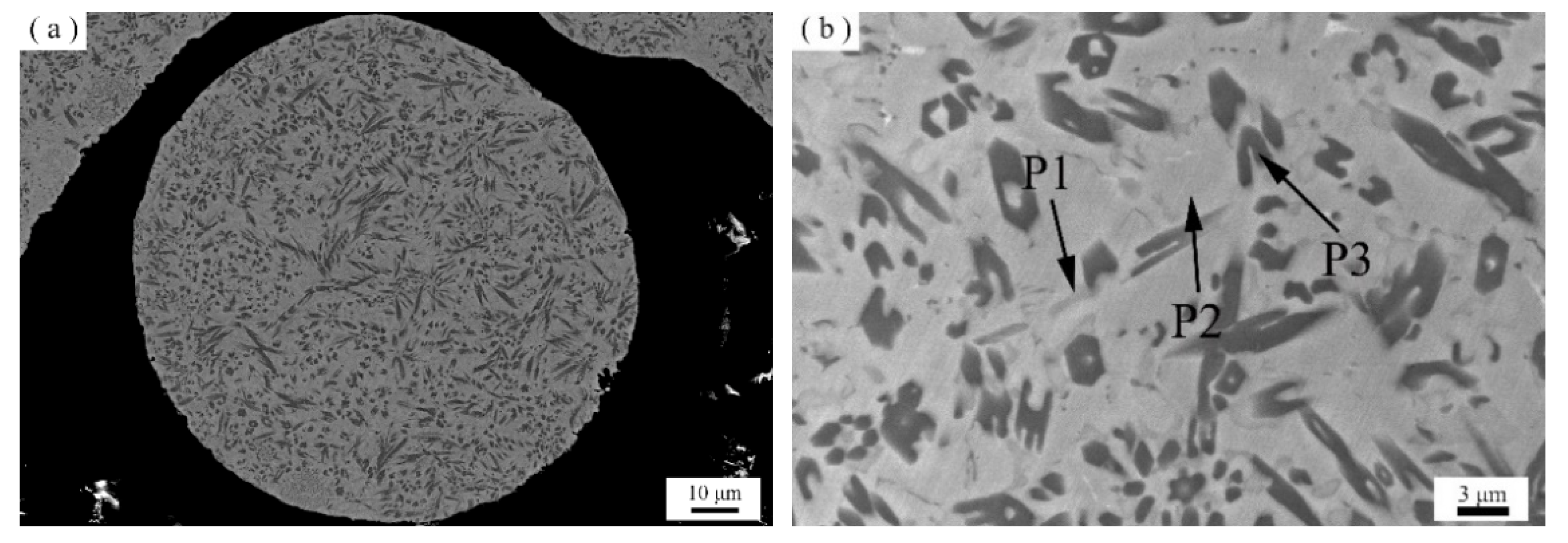
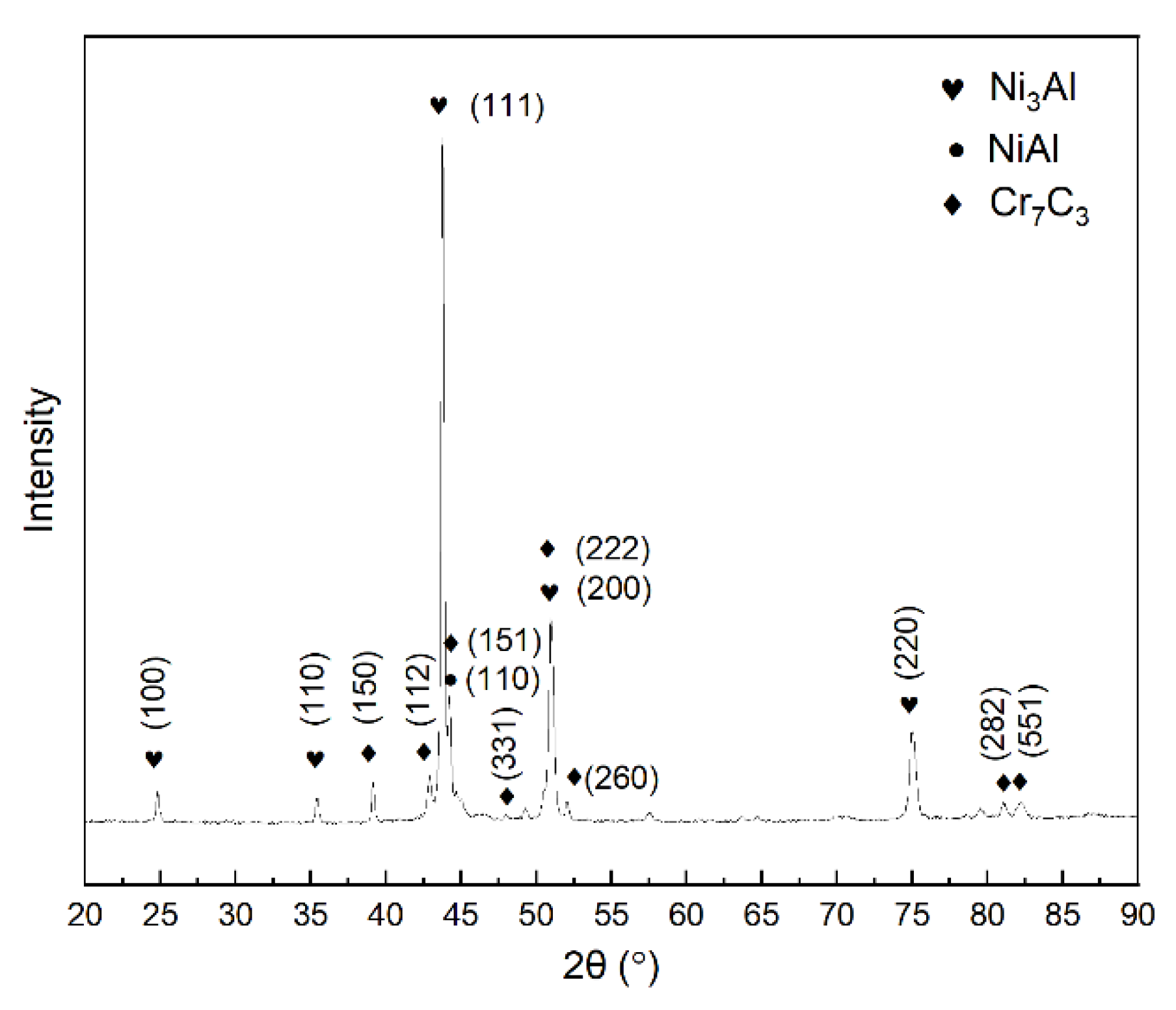
The cross section morphology and microstructure of the in situ-formed alloyed powder is shown in Figure 4. It can be seen form Figure 4a that the section morphology of the powder is well distributed, and the black phase is evenly distributed on the gray matrix. Figure 4b shows a backscattering electron image of the alloyed powders, and there are three different color areas, marked as P1, P2, and P3. In the process of powder preparation, Cr element will diffuse into the Ni3Al crystal structure, partially replacing both the Ni and Al elements, resulting in NiAl phase formation [29]. The XRD pattern of the alloyed powders, shown in Figure 5, reveal that there are three phases of Ni3Al, NiAl, and Cr7C3 in the powder. At the same time, the diffraction peaks of Ni3Al shift due to a lattice spacing change. When Cr enters the crystal structure of Ni3Al, it has a better affinity with the Al element, so it will preferentially occupy the position of Al, resulting in an increase to the crystal plane spacing. Therefore, it can be concluded that P1 is the NiAl phase, P2 is the Ni3Al phase, and P3 is Cr7C3 the phase.

3.2. Microstructure and Phase Composition of Cladding Layer

Figure 6a,b shows the section morphology of the alloyed powder cladding layer and the mixed powder cladding layer, respectively. The cladding layer structures are relatively dense and uniform. Moreover, the wetting angle of the cladding layer is relatively large, which is conducive to multi-lap bonding. The fast laser cladding process led the solidification rate of molten pool being higher than the rate of bubble escape, resulting in the formation of micropores [30]. In addition, it can be seen that the substrate material was partially re-melted, which suggest that strong metallurgical bonding was created between the cladding layer and the substrate. Figure 6c,e shows a similar local microstructure in the alloyed powder cladding layer, a uniform distribution of the phase constitution, and regular patterns. Figure 6d,f shows different morphology from the mixed powder cladding layer. It can be seen that the morphology, size, and distribution of carbides in the two areas are different and less regular. It may be concluded that the size of particles in the black strengthening phase in the cladding layer prepared by the alloyed powders is consistent, with more uniform and regular distribution.
Figure 7 shows that the alloyed powder cladding layer is mainly composed of Ni3Al, Cr7C3 and NiAl phases. Additionally, the mixed powder cladding layer is varied, being composed of Ni3Al, Cr7C3, Cr3C2 and NiAl phases. In theory, chromium carbide may exist in three forms, Cr3C2, Cr7C3 and Cr23C6, and their Gibbs energy is [31] calculated respectively as:
G f 0 ( Cr 3 C 2 ) = 54,344 19.57   T ( ± 9400 )   J / mol
G f 0 ( Cr 7 C 3 ) = 92,067 41.5   T ( ± 2800 )   J / mol
G f 0 ( Cr 23 C 6 ) = 236,331 86.2   T ( ± 10,000 )   J / mol
At the same temperature, the Gibbs energy of the three kinds of chromium carbide is Cr3C2 > Cr7C3 > Cr23C6. The smaller the Gibbs free energy, the more stable it is. However, studies have shown that the most thermodynamically stable Cr23C6 can be formed only in the case of long-term heat treatment, while the materials in the laser cladding state are all in a non-equilibrium stage of solidification. Considering the Cr/C ratio in the powders, the phase in the alloyed powder cladding layer is excepted to comprise Cr7C3 [32]. EDS mapping of the alloyed powder cladding layer is shown in Figure 8. Considering the result of EDS mapping together with XRD analysis data, it can be determined that the black Cr and C elements containing rich phases could be a strengthening phase of Cr7C3. The gray area and the white area are rich in both Ni and Al, with small amounts of Cr and C. It should also be noted that the positions of the Ni3Al and NiAl diffraction peaks of the cladding layer are offset compared to those of standard PDF cards. This is because the Cr and C elements enter the Ni3Al and NiAl crystal structures and replace the occupied positions of Ni or Al, which caused lattice distortion and spacing change. The Al element content of the gray areas differs, with the dark gray area determined as NiAl and the white gray area as Ni3Al. The rapid thermal process of laser cladding leads to non-equilibrium state of liquid solidification and, thus, an unequilibrium NiAl phase was formed. The NiAl phase may strengthen the Ni3Al matrix [33]. The residual coarse Cr3C2 in the mixed powder cladding layer is due to the large particle size of Cr3C2 in the mixed powder cladding layer, which only partially dissolves in the cladding layer [34].
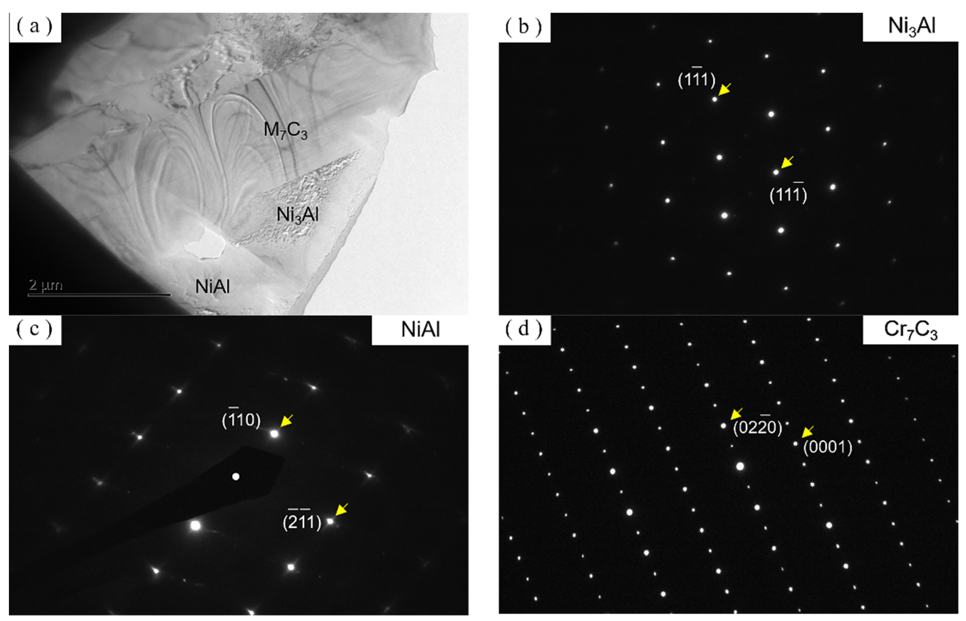
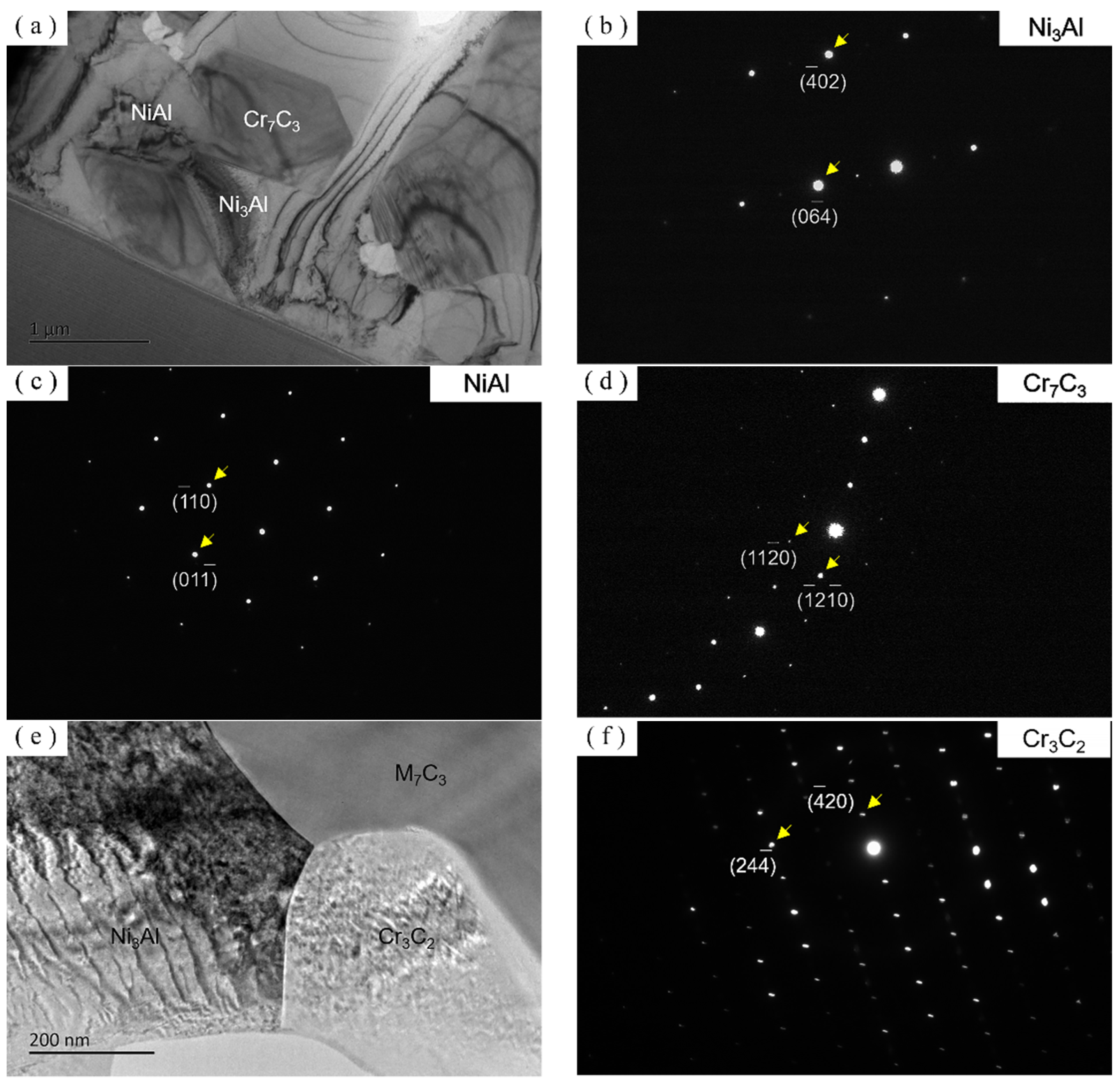
Figure 9 shows TEM images and selected electron diffraction patterns of the alloyed powder cladding layer. There are three phases in the TEM images of the alloy powder cladding layer shown in Figure 9a. Figure 9b shows the electron diffraction pattern of the Ni3Al fcc structure. Figure 9c shows the electron diffraction pattern of the NiAl bcc structure. Figure 9d shows the electron diffraction pattern of the Cr7C3 hcp structure. Figure 10 shows the TEM image and the selected electron diffraction pattern of the alloyed powder cladding layer. Figure 10a–e shows TEM images of the Ni3Al, NiAl, Cr7C3, and Cr3C2 phases, respectively. Figure 10b shows the electron diffraction pattern of the Ni3Al fcc structure; Figure 10c shows the electron diffraction pattern of the NiAl bcc structure; and Figure 10d shows the electron diffraction pattern of the Cr7C3 hcp structure. The electron diffraction pattern of the Cr3C2 bcc structure is shown in Figure 10f.
As mentioned above, there is are obvious differences in microstructure between the images represented in Figure 6c,e and those in Figure 6d,f. The mixed powder cladding layers are composed of four phases, consisting of a matrix of Ni3Al, NiAl, Cr7C3, and the partially dissolved Cr3C2, revealed by XRD and TEM analyses; see Figure 6d,f. Some of the coarse Cr3C2 particles and the Cr7C3 particles in the mixed powder cladding layer are bulky and uneven. The mixed powders were mixed by mechanical stirring of Ni3Al and Cr3C2. The difference in shape and density between Ni3Al and Cr3C2 leads to a difference in carrying capacity during the coaxial powder feeding process, resulting in an uneven distribution of Cr3C2 in the mixed powder entering the molten pool. Since the laser cladding process is very rapid, the Cr3C2 particles have no time to fully dissolve and diffuse in molten pool, resulting in the uneven distribution of Cr7C3 particles. Additionally, some of the coarse Cr3C2 particles were retained due to their higher melting point and the shorter time of the laser cladding process. The alloyed powder cladding layer is composed of a matrix of Ni3Al and two other phases, NiAl + Cr7C3 (black). The Cr7C3 particles in the alloyed powder cladding layer are tiny and equally distributed; see Figure 6c,e. Because the Cr7C3 particles are relatively small and evenly distributed in each alloyed powder, in situ-formed Cr7C3 shows uniform and even dispersion without element diffusion in the process of laser cladding.

3.3. Microhardness and Wear Properties of the Cladding Layer

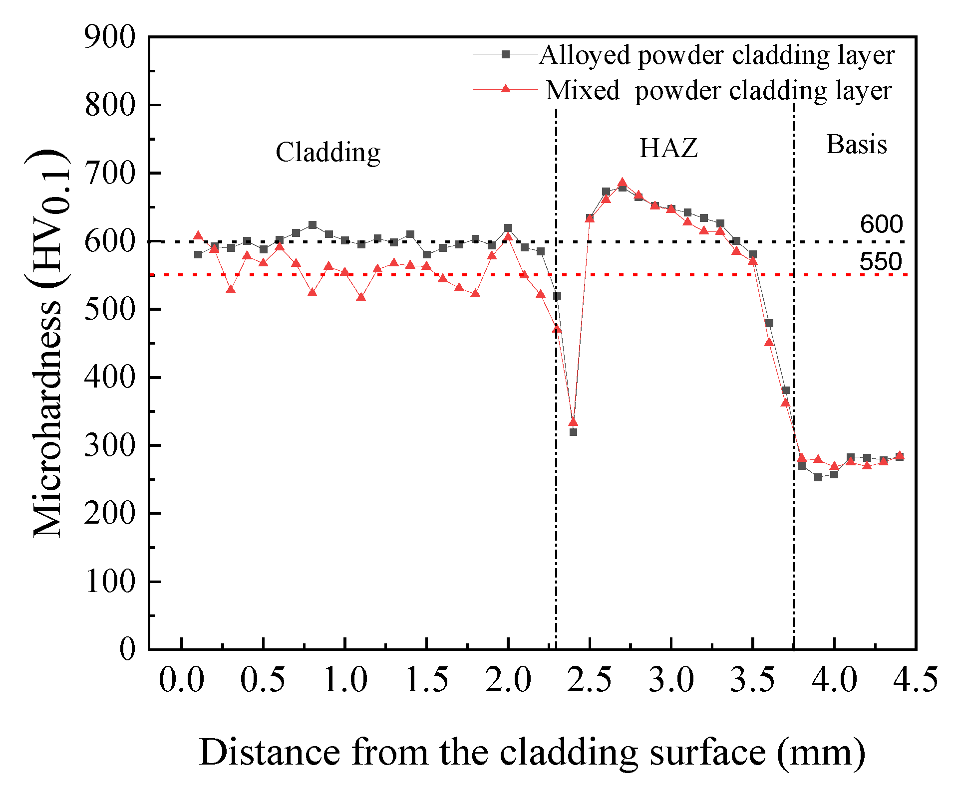
Figure 11 shows the change of microhardness from the surface to the substrate of the cladding layer. It can be seen that the two cladding layers have the same hardness variation trend. The average microhardness of the alloyed powder cladding layer is 600 ± 5 HV0.1, and remains constant. However, the average microhardness of the mixed powder cladding layer is about 550 ± 5 HV0.1, and the fluctuation range of the hardness value is relatively large. The varied microhardness of the cladding layer is related to its microstructure. In fact, the tiny Cr7C3 strengthening phase is uniformly distributed on the Ni3Al matrix in the alloyed powder cladding layer, whereas the distribution of Cr7C3 and Cr3C2 in the mixed powder cladding layer is not uniform. The thickness of the cladding layer is 2.25 ± 0.1 mm. The average microhardness of the 42CrMo matrix is about 270 ± 5 HV0.1, and the hardness of the cladding layer is more than one-fold higher than that of the substrate materials.
Figure 12 shows the dynamic friction coefficient curves of three tribo-pairs at room temperature. They reveal that the coefficient of the alloyed powder cladding layer is the lowest, which is only 0.1 ± 0.01, and the coefficient of the mixed powder cladding is 0.12 ± 0.01. The friction coefficients of the alloyed powder cladding layer and the mixed powder cladding layer remain stable at a friction stage. However, a shorter time is needed for the alloyed powder cladding layer to enter the stable friction stage, and the friction coefficient is lower; the friction coefficient of vermicular cast iron is the highest, at 0.55 ± 0.05 and fluctuates greatly over time. The results indicated that compared to the mixed powder cladding layer, the alloyed powder cladding layer has an obviously reduced friction coefficient of the friction pair and displays better tribological performance.
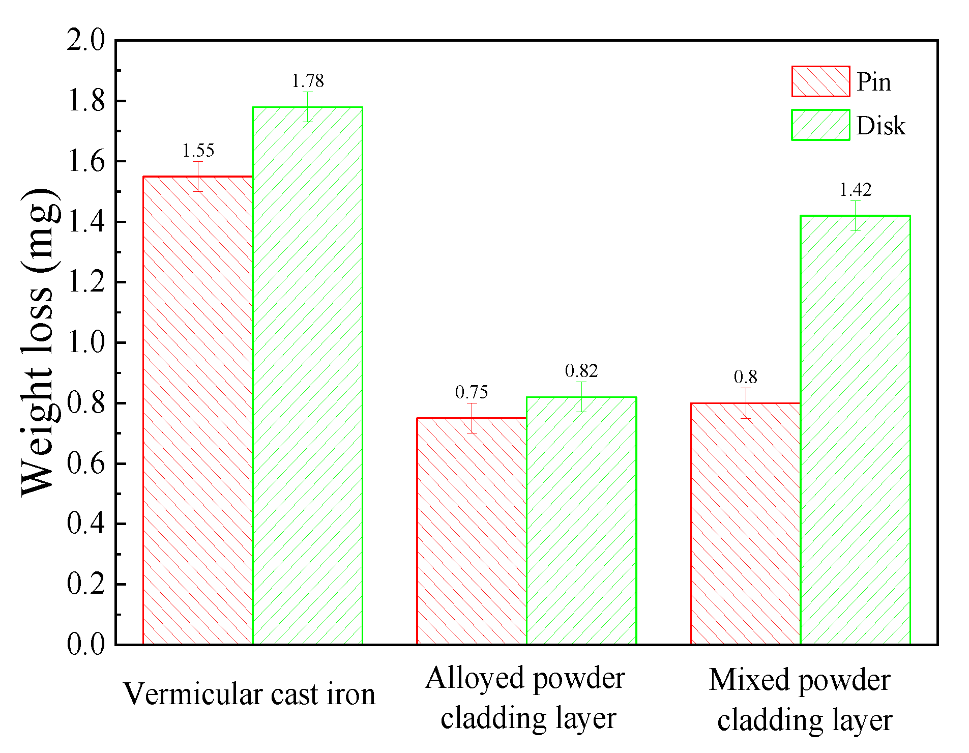
Figure 13 shows the weight loss of the three tribo-pairs above. The wear amounts of the two cladding layers are smaller, which is half that of the vermicular graphite cast iron, indicating that the addition of chromium carbide in the Ni3Al composite for coating has greatly improved the wear resistance of the material. It should also be noted that the wear amount of the alloyed powder cladding layer is lower than that of the mixed powder cladding layer. Compared with vermicular cast iron, both of the cladding layers are more friendly to their counterparts. In fact, the counterpart’s loss weight of the alloyed powder cladding layer show even better (0.82 ± 0.05 mg) than the mixed powder cladding layer (1.42 ± 0.05 mg).

4. Discussion

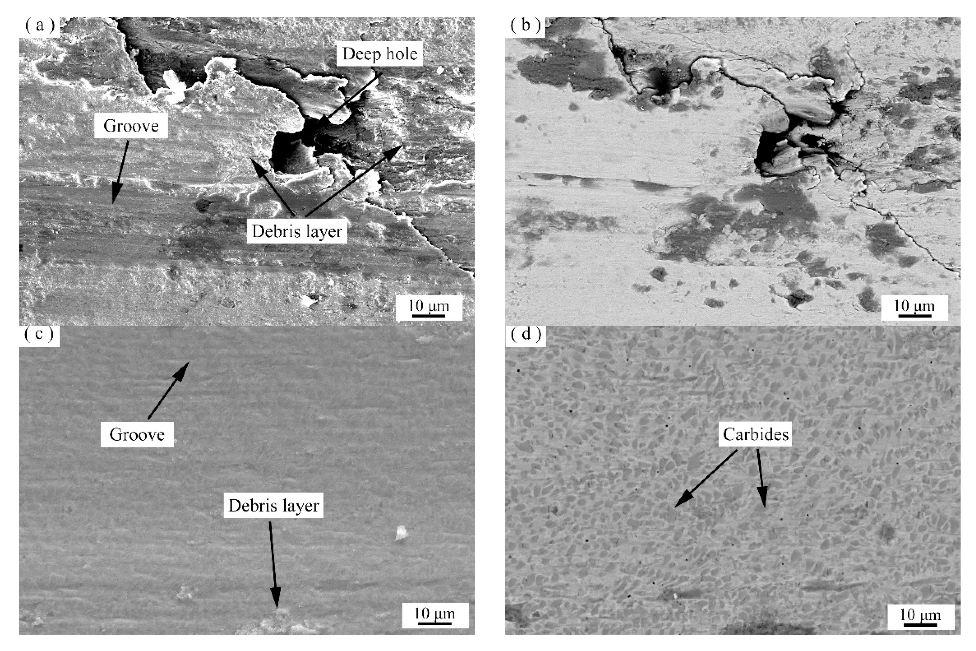
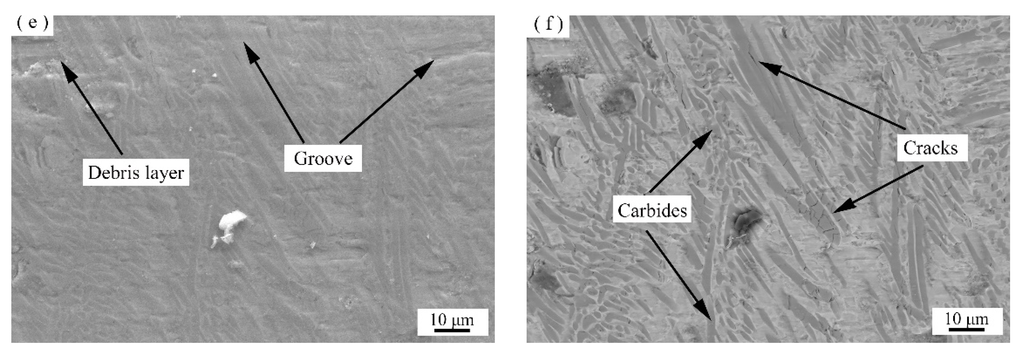
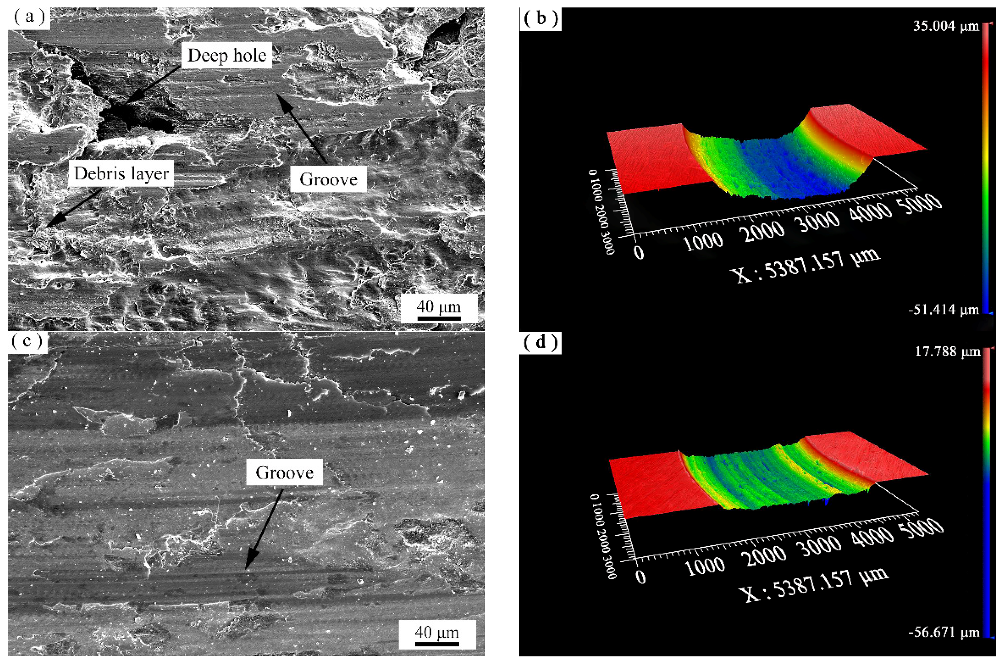
Secondary electron images (SEI) and backscattering electron images (BEI) of the worn surfaces of the cladding layers are shown in Figure 14. Grooves, debris layers, and microcracks on the surface of the cladding layers are indicated. The vermicular cast iron surface has deep grooves and large debris layers, as seen in Figure 14a. The study indicated that the wear mechanisms are mainly adhesive wear and abrasive wear. There are only some small and discontinuous grooves on the surface of the cladding layer in Figure 14c,d, and the wear marks are blocked by the hard strengthening phase Cr7C3, which may improve the hardness and wear resistance of the material, and the wear type is abrasive wear. Figure 14e,f shows the topography of the worn surface of the mixed powder cladding layer. There are also grooves on the worn surface, but they are deeper than those on the worn surface of the alloyed powder cladding layer. The debris layers and cracks exist around the large Cr3C2 particles on the worn surface. The friction mechanisms are types of abrasive wear and trace adhesion wear. The wear resistance of the alloyed powder cladding layer and the mixed powder cladding layer is better than that of the vermicular graphite cast iron, mainly due to a higher work hardening ability of Ni3Al-matrix. During the process of friction, a thickness gradient verified work hardening layer is formed on the surface of Ni3Al material, which improves the wear resistance of the material [35]. At the same time, the raised Cr7C3 in the cladding layer can separate the friction surfaces well and reduce the shear force between the friction pairs, thus reducing the friction coefficient and the amount of wear [36].
The wear resistance of the alloyed powder cladding layer is better than that of the mixed powder cladding layer, which can be attributed to the following reasons: (1) The Cr7C3 particles in the alloyed powder cladding layer are relatively small and evenly distributed, which can more effectively separate the contact surfaces of friction pairs; the uneven distribution of Cr7C3 in the mixed powder cladding layer leads to a less effective separation of some contacted areas of the friction pair, and then adhesive wear is formed in these areas. (2) The Cr7C3 particles in the alloyed powder cladding layer are relatively small, more evenly dispersed, and held tightly by the matrix, which may effectively block and cut off local wear, and then make the debris smaller as a result. Coarse Cr3C2 particles exist in the cladding layer of the mixed powder, and these particles will create deep trenches on the surface of the grinding disk, even causing fatigue cracks around the larger Cr3C2 particles during a longer period of wear. The created bigger debris will cause more serious and intensified wear and deeper wear marks [37,38].
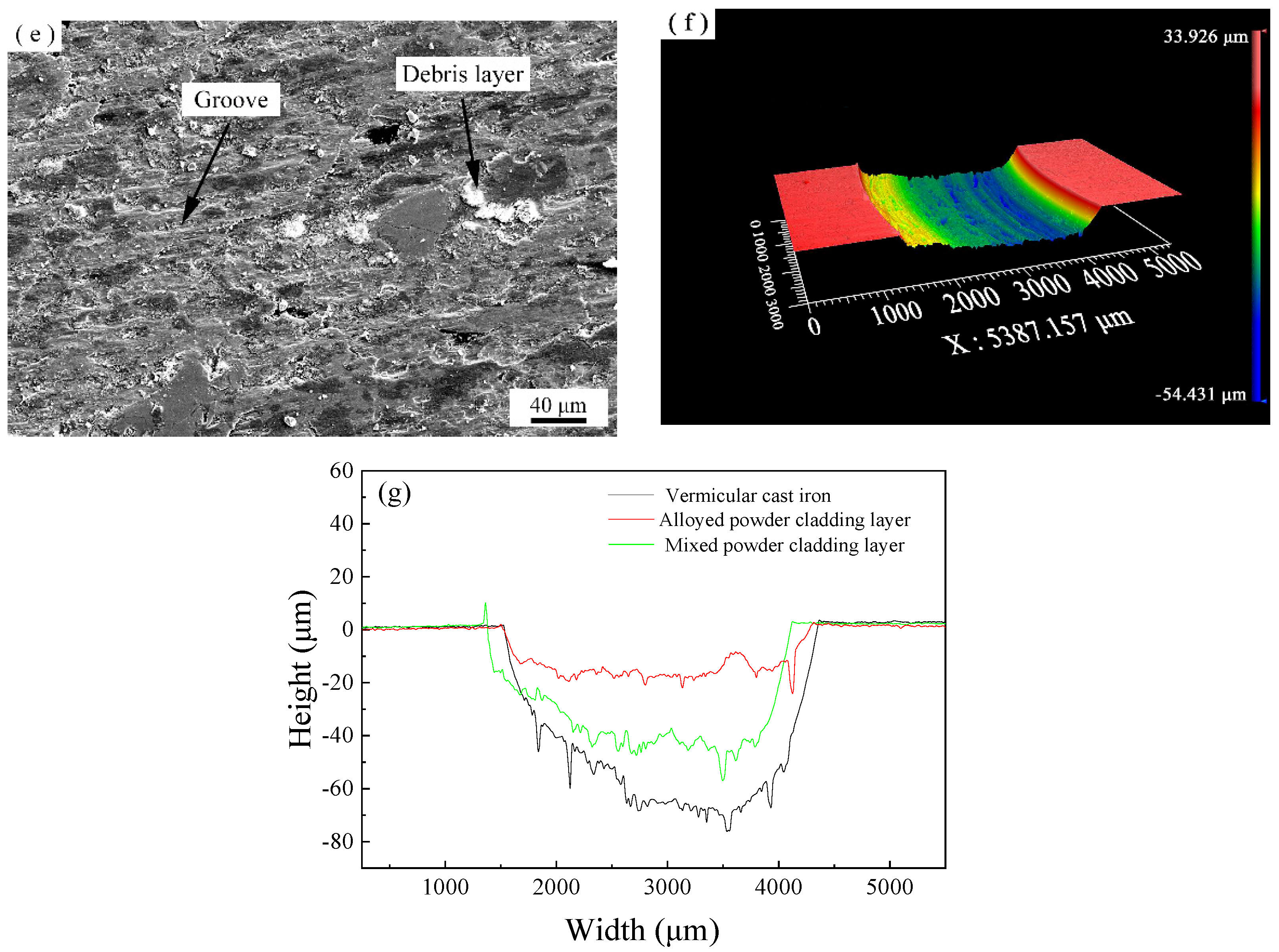
The evaluation of wear performance depends not only on the low friction coefficient, wear quantity and better wear morphology of the friction material itself, but also on the wear quantity and wear morphology of its counterpart. Figure 15 shows the microstructure of the worn surfaces and 3D profile of the wear mark depth of the relative counterpart. As can be seen from the figures, the scratches on the surface of the counterpart disk against the cladding layer are relatively shallow, and only a small amount of the debris layer is on its surface. The vermicular cast iron pin made the grooves deeper, with a large debris layer on the surface of the counterpart disk. From Figure 15g, it can be seen that the wear depth on the disk related to the alloyed powder cladding layer and the mixed powder cladding layer is shallow. Additionally, the average wear depths of these disks are 18 ± 0.5, 50 ± 0.5, 70 ± 0.5 μm, corresponding to the alloyed powder cladding layer, the mixed powder cladding layer, and the vermicular cast iron, respectively. These results are consistent with the weight loss of the disk shown in Figure 13.
The in situ-formed Cr7C3 in the cladding layer can effectively separate the friction pair, and the fallen wear debris can be discharged over time to reduce the friction shear force on the surface of the grinding disk, decreasing the probability of the generation and propagation of defects, such as wear surface cracks, and reducing wear of the grinding disk [39].

5. Conclusions

(1)
The alloyed powder cladding layer is mainly composed of Ni3Al, NiAl and in situ Cr7C3, and the in situ-formed Cr7C3 particles are tiny and evenly dispersed; the mixed powder cladding layer contains Ni3Al, NiAl, in situ Cr7C3 and partially undissolved Cr3C2, and the distribution of the Cr7C3 particles is uneven.
(2)
The average friction coefficient of the alloyed powder cladding layer is 0.1 ± 0.01, which is slightly lower than 0.12 ± 0.01 of the mixed powder cladding layer, and far lower than 0.55 ± 0.05 of vermicular cast iron. The wear loss of the disks related to the alloyed powder cladding layer is 0.82 ± 0.05 mg, lower than 1.42 ± 0.05 mg of the mixed powder cladding layer, and even lower compared to that of the vermicular cast iron (1.78 ± 0.05 mg).
(3)
The difference in tribological performance between the alloy powder and mixed powder cladding layer is mainly due to their differences in their microstructure. In situ-formed tiny Cr7C3 particles are evenly dispersed on the intermetallic matrix in the alloyed powder cladding layer, which can effectively separate the friction surface and block scratches, whereas Cr7C3 particles generated in the mixed powder cladding layer are unevenly distributed, with inferior performance in terms of separating some surface areas of tribo-pairs. Moreover, the undissolved coarse Cr3C2 particles may scratch the counterpart pair more seriously and intensify the wear. Therefore, the alloyed powder cladding layer designed, produced, and tested in this study not only has improved tribological properties but also results in less damage to counterpart materials.

Author Contributions

Conceptualization, F.Y., Z.L. and C.C.; methodology, Z.L. and L.Z.; validation, F.Y., C.C. and L.Z.; formal analysis, Z.L.; investigation, Y.F. and L.F.; resources, L.Z.; data curation, Z.L. and C.C.; writing—original draft preparation, Z.L. and F.Y.; writing—review and editing, F.Y. and Z.L.; visualization, Y.F.; supervision, L.Z., Y.C., Y.P., Z.T. and C.L.; project administration, L.Z.; funding acquisition, L.Z. and L.F. All authors have read and agreed to the published version of the manuscript.

Funding

This research was funded by the National Key R&D Program of China, grant number 2020YFE0200900 and the Natural Science Foundation of Henan, grant number 202300410143.

Institutional Review Board Statement

Not applicable.

Informed Consent Statement

Not applicable.

Data Availability Statement

Not applicable.

Conflicts of Interest

The authors declare no conflict of interest.

References

  1. Li, J.; Peng, Y.; Zhang, J.; Yin, S.; Ding, J.; Wu, Y.; Wu, J.; Chen, X.; Xia, X.; He, X.; et al. Cyclic oxidation behavior of Ni3Al-based superalloyed. Vacuum 2019, 169, 108938. [Google Scholar] [CrossRef]
  2. Mao, R.; Fan, Z.; Xiang, D. Enhanced mechanical properties of tungsten alloy by synergistic strengthening of flaky Ni3Al and Al2O3 nano-particles. J. Alloys Compd. 2021, 898, 162790. [Google Scholar] [CrossRef]
  3. Khoei, A.R.; Eshlaghi, G.T.; Shahoveisi, S. Atomistic simulation of creep deformation mechanisms in nickel-based single crystal superalloys. Mater. Sci. Eng. A 2021, 809, 14097. [Google Scholar] [CrossRef]
  4. Gong, S.; Shang, Y.; Zhang, J.; Guo, X.; Lin, J.; Zhao, X. Application and research of typical intermetallics-based high temperature structural materials in China. Acta Met. Sin 2019, 55, 1067–1076. [Google Scholar] [CrossRef]
  5. Wen, Y.; Sun, J.; Huang, J. First—principles study of stacking fault energies in Ni3Al intermetallic alloyeds. Trans. Nonferrous Met. Soc. China 2012, 22, 661–664. [Google Scholar] [CrossRef]
  6. Kruml, T.; Conforto, E.; Piccolo, B.L.; Caillard, D.; Martin, J.L. From dislocation cores to strength and work-hardening: A study of binary Ni3Al. Acta Mater. 2002, 50, 5091–5101. [Google Scholar] [CrossRef]
  7. Mao, Q.; Yang, Q.; Xiong, W.; LI, S.; Zhang, M.; Ruan, L. Corrosion behavior of Ni3Al-bonded TiC-based cermets in H2SO4 and NaOH solutions. Ceram. Int. 2018, 44, 13303–13312. [Google Scholar] [CrossRef]
  8. Li, S.; Feng, D.; Luo, H. Microstructure and abrasive wear performance of chromium carbide reinforced Ni3Al matrix composite coating. Surf. Coat. Technol. 2007, 201, 4542–4546. [Google Scholar] [CrossRef]
  9. Liu, W.; Zhang, F.; Lu, J.; Chen, J.; Huang, H.; Zhou, Y.; Tang, H. Preparation of Ni3Al bonded diamond core drill with Ni–Cr alloyed and its performance on glass–ceramic. Ceram. Int. 2018, 44, 23080–23087. [Google Scholar] [CrossRef]
  10. Colaco, R.; Vilar, R. Abrasive wear of metallic matrix reinforced materials. Wear 2003, 255, 643–650. [Google Scholar] [CrossRef]
  11. Cios, G.; Bala, P.; Stepien, M.; Górecki, K. Microstructure of cast Ni-Cr-Al-C alloy. Arch. Metall. Mater. 2015, 60, 145–148. [Google Scholar] [CrossRef]
  12. Gong, K.; Zhou, Z.; Shum, P.W.; Luo, H.; Tian, Z.; Li, C. Tribological evaluation on Ni3Al-based alloyed and its composites under unlubricated wear condition. Wear 2011, 270, 195–203. [Google Scholar] [CrossRef] [Green Version]
  13. Fu, L.; Han, W.; Gong, K.; Bengtsson, S.; Dong, C.; Zhao, L.; Tian, Z. Microstructure and tribological properties of Cr3C2/Ni3Al composite materials prepared by hot isostatic pressing (HIP). Mater. Des. 2017, 115, 203–212. [Google Scholar] [CrossRef] [Green Version]
  14. Gong, K.; Luo, H.; Feng, D.; Li, C. Wear of Ni3Al-based materials and its chromium-carbide reinforced composites. Wear 2008, 265, 1751–1755. [Google Scholar] [CrossRef] [Green Version]
  15. Luo, H.; Gong, K.; Li, S.; Cao, X.; Zhang, X.; Feng, D.; Li, C. Abrasive wear comparison of Cr3C2/Ni3Al composite and stellite 12 alloyed cladding. J. Iron Steel Res. Int. 2007, 14, 15–20. [Google Scholar] [CrossRef] [Green Version]
  16. Li, S.; Wu, M.; Sun, L.; Jiang, L.; Han, Y. Fretting wear resistance of ATW Cr3C2/Ni3Al composite hardfacing on IC6SX. Mater. Sci. Forum 2010, 654, 532–537. [Google Scholar] [CrossRef]
  17. Ma, Q.; Dong, Z.; Ren, N.; Hong, S.; Chen, J.; Hu, L.; Meng, W. Microstructure and mechanical properties of multiple in-situ-phases-reinforced nickel composite coatings deposited by wide-band laser. Coatings 2021, 11, 36. [Google Scholar] [CrossRef]
  18. Sun, F.; Cai, K.; Li, X.; Pang, M. Research on laser cladding Co-based alloy on the surface of vermicular graphite cast iron. Coatings 2021, 11, 1241. [Google Scholar] [CrossRef]
  19. Gao, J.; Wu, C.; Hao, Y.; Xu, X.; Guo, L. Numerical simulation and experimental investigation on three-dimensional modelling of single-track geometry and temperature evolution by laser cladding. Opt. Laser Technol. 2020, 129, 106287. [Google Scholar] [CrossRef]
  20. Weisheit, A.; Rittinghaus, S.; Dutta, A.; Majumdar, J.D. Studies on the effect of composition and pre-heating on microstructure and mechanical properties of direct laser clad titanium aluminide. Opt. Lasers Eng. 2020, 131, 106041. [Google Scholar] [CrossRef]
  21. Li, M.; Han, B.; Song, L.; He, Q. Enhanced surface layers by laser cladding and ion sulfurization processing towards improved wear-resistance and self-lubrication performances. Appl. Surf. Sci. 2020, 503, 144226. [Google Scholar] [CrossRef]
  22. Chen, C.; Zhao, X.; Fang, Q.; Zhao, L.; Han, W.; Peng, Y.; Yin, F.; Tian, Z. Wear Resistance of Laser Cladding Ni3Al/Cr3C2 Composites. Rare Met. Mater. Eng. 2020, 49, 1388–1394. (In Chinese) [Google Scholar]
  23. Aoki, K.; Osamu, I. Improvement in room temperature ductility of the L12 type intermetallic compound Ni3Al by boron addition. J. Jpn. Inst. Met. Mater. 1979, . 43, 1190–1196. [Google Scholar] [CrossRef] [Green Version]
  24. Yuan, J.; Yu, Y.; Shen, J. Cermet composite coating with a ductile Ni3Al binder phase and an in-situ Cr7C3 augmented phase. Intermetallics 2021, 138, 107300. [Google Scholar] [CrossRef]
  25. Zhu, H.; Shen, J.; Gao, F.; Yu, Y.; Li, C. Microstructure and sliding wear performance of Cr7C3-(Ni,Cr)3(Al,Cr) coating deposited from Cr7C3 in situ formed atomized powder. J. Therm. Spray Technol. 2017, 26, 254–264. [Google Scholar] [CrossRef]
  26. Guo, S.; Chen, Z.; Zhang, Q.; Lou, C.; Yao, J. Effects of different pressures on laser cladding special powder prepared by gas atomization. Chin. J. Lasers 2013, 40, 150–155. [Google Scholar] [CrossRef]
  27. Sui, Q.; Zhou, H.; Zhang, D.; Chen, Z.; Zhang, P. Imposed thermal fatigue and postthermal-cycle wear resistance of biomimetic gray cast iron by laser treatment. Metall. Mater. Trans. A 2017, 48, 3758–3769. [Google Scholar] [CrossRef]
  28. Liu, H.; Yu, G.; He, X.; Li, S. Influence of powder properties on powder flow field in coaxial Powder feeding laser cladding. Chin. J. Lasers 2013, 40, 102–110. (In Chinese) [Google Scholar]
  29. Li, Y.; Li, C.; Yu, L.; Ma, Z.; Li, H.; Liu, Y. Characterization of γ′ precipitate and γ/γ′ interface in polycrystalline Ni3Al-based superalloys. Vacuum 2020, 176, 109310. [Google Scholar] [CrossRef]
  30. Zhang, T.; Sun, R. Study on pores and crack sensitivity of Ni- based composite coating by laser cladding. IOP Conf.Ser. Mater. Sci. Eng. 2015, 87, 012096. [Google Scholar] [CrossRef] [Green Version]
  31. Anthonysamy, S.; Ananthasivan, K.; Kaliappan, I.; Chandramouli, V.; Rao, P.R.V.; Mathews, C.K.; Jacob, K.T. Gibbs energies of formation of chromium carbides. Metall. Mater. Trans. A 1996, 27, 1919–1924. [Google Scholar] [CrossRef]
  32. Tiegs, T.N.; Alexander, K.B.; Plucknett, K.P.; Menchhofer, P.A.; Becher, P.F.; Waters, S.B. Ceramic composites with a ductile Ni3Al binder phase. Mater. Sci. Eng. A 1996, 209, 243–247. [Google Scholar] [CrossRef]
  33. Gong, K.; An, T.; Zhou, Z.; Tian, Z.; Li, C. Study on Wear Behaviors of Ni3Al/Cr-Carbides Cladding Layer on High Strength Steel Substrate. Adv. Mater. Res. 2014, 936, 1273–1282. [Google Scholar] [CrossRef] [Green Version]
  34. Vlasyuk, R.Z.; Radomysel’skii, I.D.; Smirnov, V.P.; Sotnik, A.A. Dissolution of Cr3C2 in a Nickel matrix during sintering I. Reaction of chromium carbide with nickel during solid-phase sintering. Powder Metall. Met. Ceram. 1985, 24, 269–273. [Google Scholar] [CrossRef]
  35. Fu, L.; Han, W.; Zhao, L.; Gong, K.; Bengtsson, S.; Zhou, M.; Li, C.; Tian, Z. Effects of Cr3C2 content and temperature on sliding friction and wear behaviors of Cr3C2/Ni3Al composite materials. Wear 2018, 414–415, 163–173. [Google Scholar] [CrossRef]
  36. Zhai, W.; Shi, X.; Wang, M.; Xu, Z. Grain refinement: A mechanism for graphene nanoplatelets to reduce friction and wear of Ni3Al matrix self-lubricating composites. Wear 2014, 310, 33–40. [Google Scholar] [CrossRef]
  37. Yuan, Y.; Li, Z. Effects of rod carbide size, content, loading and sliding distance on the friction and wear behaviors of (Cr,Fe)7C3-reinforced α-Fe based composite coating produced via PTA welding process. Surf. Coat. Technol. 2014, 248, 9–22. [Google Scholar] [CrossRef]
  38. Hu, J.; Li, D.; Llewellyn, R. Computational investigation of microstructural effects on abrasive wear of composite materials. Wear 2005, 259, 6–17. [Google Scholar] [CrossRef]
  39. Wesmann, J.A.R.; Espallargas, N. Effect of atmosphere, temperature and carbide size on the sliding friction of self-mated HVOF WC–CoCr contacts. Tribol. Int. 2016, 101, 301–313. [Google Scholar] [CrossRef]
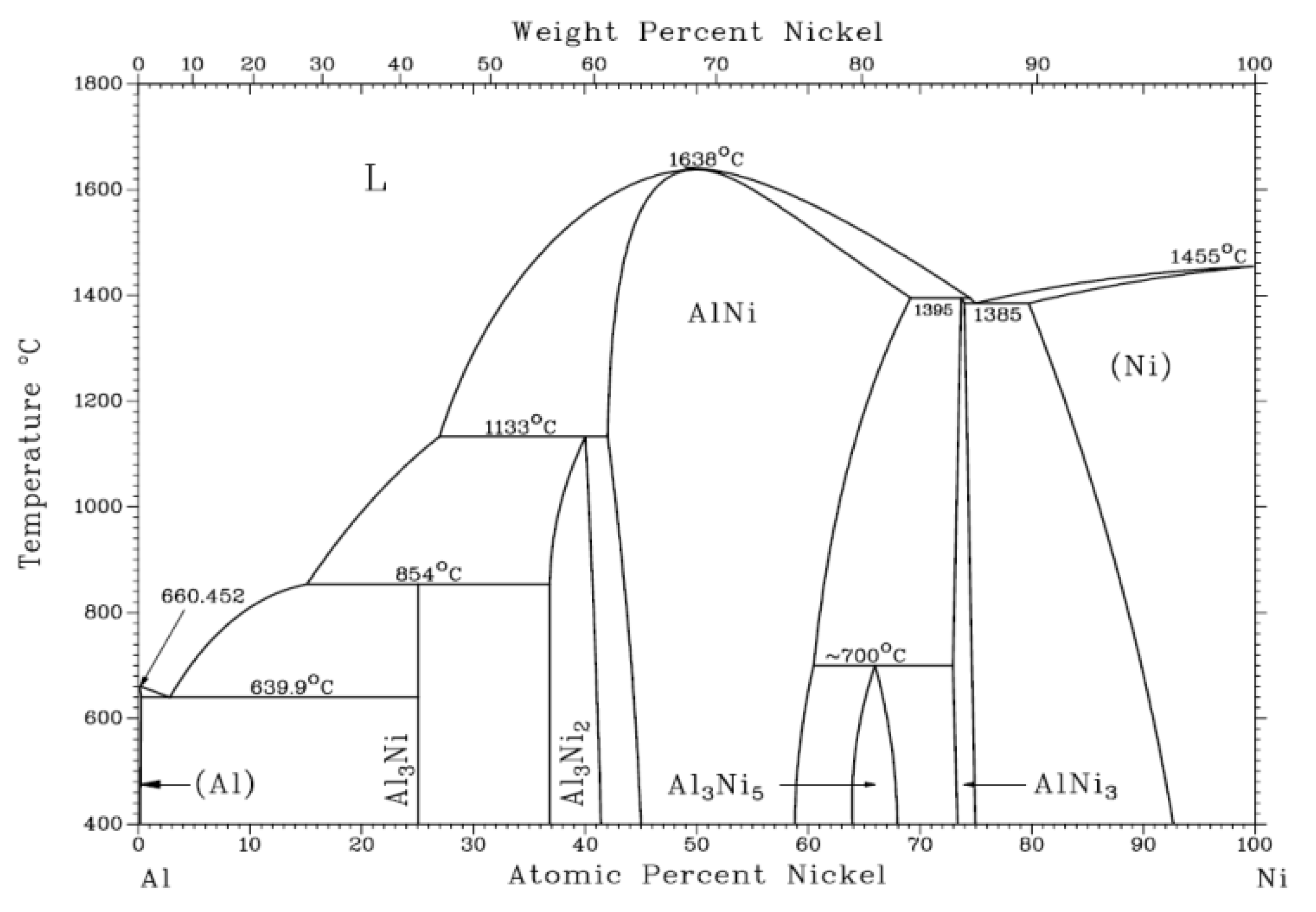
Figure 1. NiAl phase diagram.
Coatings 12 00105 g001
Figure 2. Morphology of the alloyed powder (SEM).
Coatings 12 00105 g002
Figure 3. Particle size distribution of the alloyed powder.
Coatings 12 00105 g003
Figure 4. Cross section morphology (a) and microstructure (b) of the alloyed powder.
Coatings 12 00105 g004
Figure 5. XRD spectrum of the alloyed powder.
Coatings 12 00105 g005
Figure 6. Macrostructure and microstructure morphologies of cladding layer cross section. (a,c,e) from the alloyed powder cladding layer; (b,d,f) from the mixed powder cladding layer.
Coatings 12 00105 g006aCoatings 12 00105 g006b
Figure 7. XRD spectra of the two cladding layers: (a) the alloyed powder cladding layer; (b) the mixed powders cladding layer.
Coatings 12 00105 g007
Figure 8. Element distribution map of the alloyed powder cladding layer.
Coatings 12 00105 g008
Figure 9. TEM results of the alloyed powder cladding layer. (a) TEM image of Ni3Al, NiAl, and Cr7C3; (bd) electron diffraction patterns of Ni3Al, NiAl, and Cr7C3, respectively.
Coatings 12 00105 g009
Figure 10. TEM results of the mixed powder cladding layer. (a,e) TEM images of Ni3Al, NiAl, Cr7C3, and Cr3C2; (bd) electron diffraction patterns of Ni3Al, NiAl, and Cr7C3 respectively; (f) electron diffraction pattern of Cr3C2.
Coatings 12 00105 g010
Figure 11. Microhardness of the two cladding layers.
Coatings 12 00105 g011
Figure 12. Friction coefficient of three tribo-pairs as a function of sliding time.
Coatings 12 00105 g012
Figure 13. Weight loss of three friction pairs vs. sliding time at room temperature.
Coatings 12 00105 g013
Figure 14. Secondary electron images (a,c,e) and backscattering electron images (b,d,f) of worn surfaces of vermicular cast iron, the alloyed powder cladding layer, and the mixed powder cladding layer, respectively.
Coatings 12 00105 g014aCoatings 12 00105 g014b
Figure 15. Worn surface morphologies and 3D profiles of counterpart disks: (a,b) vermicular cast iron; (c,d) the alloyed powder cladding layer; (e,f) the mixed powder cladding layer; (g) contrast diagram of wear depth on disk.
Coatings 12 00105 g015aCoatings 12 00105 g015b
Table 1. 42CrMo alloy steel and powders chemical composition (wt.%).
Materials/ElementsCSiMnCrMoPSFeTiNiAlB
42CrMo0.430.250.5610.220.0030.014Bal.////
Alloyed powders2.42//24.51/////Bal.9.620.02
Ni3Al powders//0.78////11.610.56Bal.9.520.02
Publisher’s Note: MDPI stays neutral with regard to jurisdictional claims in published maps and institutional affiliations.