Article

Research on Mechanical Properties of 210Cr12 Shaft Surface Processed with Rolling

1
School of Mechanical Engineering, University of Jinan, Jinan 250022, China
2
Shandong Aluminum Industry Co. Ltd., Zibo 255000, China
*
Author to whom correspondence should be addressed.
Coatings 2020, 10(7), 611; https://doi.org/10.3390/coatings10070611
Submission received: 15 April 2020 / Revised: 24 June 2020 / Accepted: 24 June 2020 / Published: 28 June 2020

Abstract

:
The rolling process is one of the most effective ways for strengthening a part’s surface. As the press force exerted on specimen in rolling process, material in the surface layer will deform plastically if the press force is sufficient. That might result in grain refinement, dislocation configuration change, or phase change in specimen surface layer material. Consequently, the surface material mechanical properties can be changed. The effects of rolling parameters on surface residual stress, micro-hardness, and surface roughness for a 210Cr12 shaft have been investigated. After the rolling process, the surface residual stress of the specimen changes from tensile stress to compressive stress, and a stable residual compressive stress layer is formed. The maximum absolute value of compressive stress can be up to 216MPa. With the increase of the value of contact stress exerted on shaft surface and the number of rolling cycles, the absolute value of residual compressive stress increases firstly and then becomes stable. With the increase of depth from shaft surface to interior, the absolute value of residual compressive stress increases initially, then decreases and disappears finally. The maximum absolute value of residual compressive stress exists at the position beneath specimen surface about 0.025mm. The depth of residual stress layer is about 0.2 mm. Research results indicate that shaft surface microhardness can be improved within small range, surface roughness can be reduced up to 67%.

1. Introduction

Machinery parts will be affected by some degrees of impact, friction, wear or corrosion in their working process. Especially under the action of long-term alternating load, fatigue failure of parts will occur, which will not only reduces mechanical efficiency but also increase power consumption and shorten service life of mechanical equipment [1,2,3]. Generally, fatigue cracks initiate and expand mainly in the material of part’s surface. Therefore, surface strengthening—i.e., improving surface strength, pre-stressing surface material, or changing the state of surface residual stress—can effectively restrain the initiation and propagation of cracks and prolong parts’ service life. Surface hardening, carburizing, shot peening, and rolling are of surface strengthening technology used in industry. Rolling strengthening is the most commonly used kind of process technology that causes plastic deformation on the surface of parts through mechanical processing.
The principle of rolling for surface strengthening is shown in Figure 1. A rolling head, such as hard and smooth ball or roller, exerts press force on the part’s surface during rolling process. Therefore, contact stress must exist between the surfaces of rolling head and part rolled by the head. Contact stress will increase with the increasing of press force exerted on part’s surface. The surface layer material will show elastic–plastic deformation as contact stress becomes larger than its yield strength. The plastic deformation of the part’s surface layer can effectively improve the surface roughness and surface hardness of rolled part. Meanwhile, the rolling process can make compressive stress in a part’s surface layer—i.e., residual compressive stress—which can directly increase the fatigue strength and fatigue life of rolled part [4,5,6].
Surface rolling strengthening technology was initially mainly used for surface strengthening of low carbon steel, alloy steel, pure aluminum, brass, and other metal materials in the 20th century. With the development and application of this technology, rolling process has gradually been applied to surface strengthening for hardened steel [7] and composite materials [8]. Juijerm et al. [9] investigated cyclic deformation behavior and s/n curves of deep rolled Al–Mg–Si–Cu alloy by stress-controlled fatigue tests at elevated temperatures up to 250 °C and compared to the polished condition as a reference. Their research shows that effects on the fatigue lifetime and residual stresses from deep rolling are significant. Avilés et al. treated AISI 1045 normalized steel by means of low-plasticity ball rolling process. Compared with the non-treated specimens, the fatigue strength of the ball-rolled specimens is increased up to 21.25%. Their work also provides experimental data and analyses of the surface roughness, fractography, in-depth residual stresses, and cyclic relaxation effects [10]. After deep cold rolling, the part can produce a larger hardening layer and residual compressive stress, which has a good finishing effect [11,12]. Bouzid et al. [13] studied the change of surface roughness of carbon steel after surface rolling strengthening. Based on the classical Hertz contact theory, a prediction model of surface roughness of rolling strengthening was established. In this model, the original surface roughness of workpiece surface was simplified and regarded as a smooth plane. The surface of the specimen was rolled by formula described in [13]. The reduction of surface roughness is regarded as the applied force smooths out the irregularities of the surface, which can be used to predict the change of surface roughness of specimens after surface rolling strengthening. Hiegemann et al. [14] considered the surface roughness of specimens before rolling and simplified the peak of surface roughness to discrete hemisphere or pyramid. The prediction model of surface roughness about rolling pressure in surface rolling strengthening was established, which has high accuracy. Korzynski et al. [15] considered the influence of surface roughness of specimens, and proposed a prediction model for the mechanism of surface rolling hardening and finishing. Based on contact mechanics, the model included the elastic–plastic properties of materials, simplified the rolling process as the action process of normal rolling pressure on strip roughness peaks, and obtained rolling pressure and roughness. The relationship between peak drop height and rolling test was carried out to verify the model, and the accuracy of the prediction model was confirmed. Zhang et al. [16] measured the residual stress on the surface of the specimens after surface rolling strengthening and carried out fatigue test. The results show that the residual compressive stress on the surface of the specimens after surface rolling strengthening has significantly increased, which can effectively inhibit the formation and development of surface cracks and increase the fatigue life of the specimens by 50%. It proves that surface rolling pressure strengthening is an effective method to improve the fatigue life of parts.
In the rolling process as mentioned above, elastic deformation and plastic deformation in the surface layer of a workpiece would result in dislocation configuration change and phase change. At the same time, subgrains of the rolling layer are refined to form gradient nanocrystalline layer [17,18,19]. After rolling, the roughness of the workpiece surface can be reduced [20], the work hardening phenomenon can be produced [21,22], and residual compressive stress can be introduced on the workpiece surface [23], which can prevent the occurrence of fatigue failure and improve the fatigue strength and fatigue life of the workpiece [24,25].
In this paper, the rolling test of 210Cr12 axle is carried out, the rules and mechanism of rolling strengthening of this kind of material are revealed, and the rolling strengthening process parameters of 210Cr12 axle parts are put forward, which provides a theoretical basis and technical support for the practical application of surface rolling strengthening technology.

2. Material and Method

2.1. Sample Preparation

Test specimens in the investigation are made up of material 210Cr12 (its chemical composition shown in Table 1). 210Cr12 forged blanks were turned into shaft specimens with diameter of 40 mm and 300 mm long. Cutting speed is 100 m/min, feeding rate is 0.05 mm/rev, cutting depth is 0.04 mm. According to the mechanical property examination for specimens after fine turning and before rolling, specimen’s surface microhardness is of 270HV0.2, residual tensile stress is of 52 MPa, the surface roughness value Ra is of 3.079μm.

2.2. Rolling Equipment

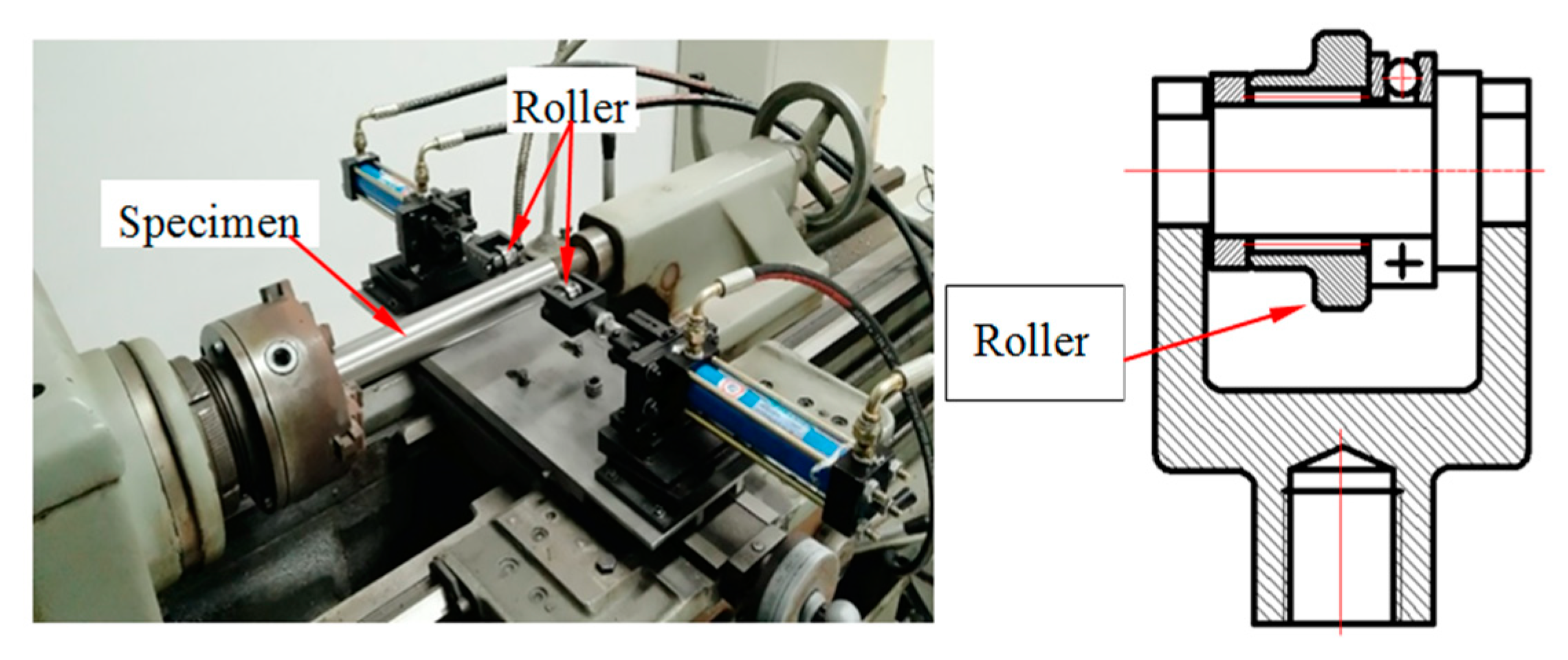
Rolling strengthening device, developed by our research team, is fixed on lathe C616 for shaft parts rolling process as shown in Figure 2. The rolling device consists of mechanical section and hydraulic system. Mechanical design of the rolling device is symmetrical structure in order to make the press forces exerted on specimen by rollers be balance, i.e., zero resultant force will be formed in rolling process, and the direction of contact stress is perpendicular to the surface of the test piece. The roller is made up of material GCr15 with diameter 35 mm and 4 mm long. The hydraulic system provides power to sustain the press force exerted on the in the rolling process.

2.3. Experimental Design

Mechanical properties of 210Cr12 shaft’s surface processed with rolling have been investigated with single-factor method. The value of contact stress and the number of rolling pass cycle were set as variables.
According to Hertz formula, the relation between contact stress and rolling force can be expressed as
δ H = F ( 1 r 1 + 1 r 2 ) π L ( 1 μ 1 2 E 1 + 1 μ 2 2 E 2 )
where δ H is contact stress, F is rolling force, L is the contact length, r 1 is the roller radius, r 2 is specimen radius, μ 1 is Poisson’s ratio of the roller, μ 2 is Poisson’s ratio of the specimen, E 1 is Young’s modulus of the roller, E 2 is Young’s modulus of the specimen.
In this study, the relationship between contact stress and rolling force can be expressed as
μ 1 = μ 2 = 0.3
E 1 = E 2 = 2.1 × 10 5 M P a
δ H = 32.05 × F
The contact stress was of 555, 641, 717, 848, and 1013 MPa respectively corresponding to the press force of 300, 400, 500, 700, and 1000 N. In addition, the number of rolling pass cycle was setup of 1, 2, 3, 5, and 8. Rolling test was carried out at fixed spindle speed of 44 rpm and feeding rate of 0.4mm per revolution of spindle.

2.4. Measurement Conditions

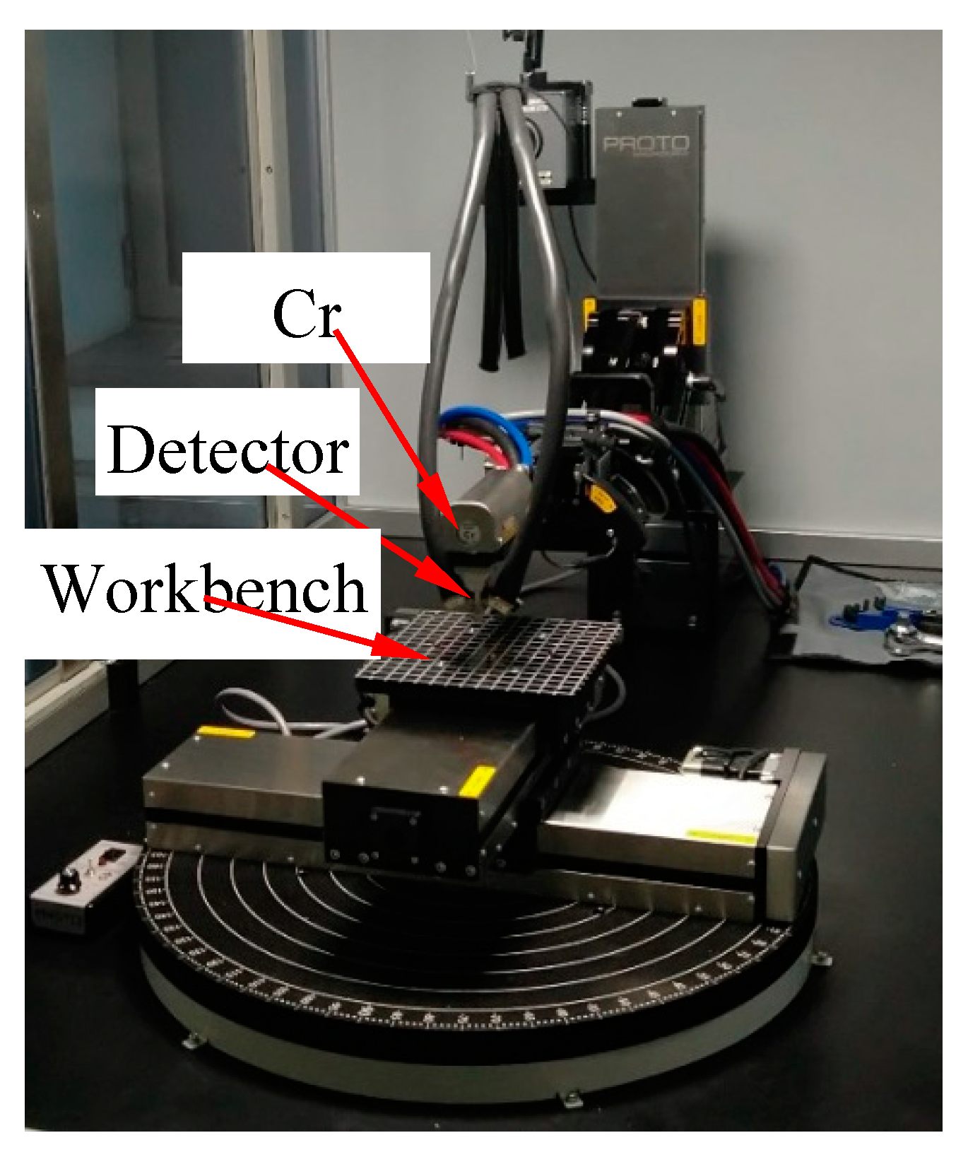
The iXRD stress analyzer produced by Proto Company of Canada as shown in Figure 3 was used to measure the residual stress for 210Cr12 shaft specimen. Chrome target was used with Bragg angle 156°. The working voltage in the X-ray tube was 20 kV, the working current was 4 mA, the exposure time was 1 s, the number of exposures was 10, and the diameter of the collimator was 1 mm. The measurement error is ±10 MPa. The studied direction of residual stress was parallel to the direction of rolling of the specimen. The initial residual stress on the specimen surface was tensile stress of 52 MPa. The residual stress on the specimen surface after rolling with different parameters is shown in Table 2.

3. Experimental Investigation on Rolling Process for 210Cr12 Shaft

3.1. Effect of Rolling on Residual Stress

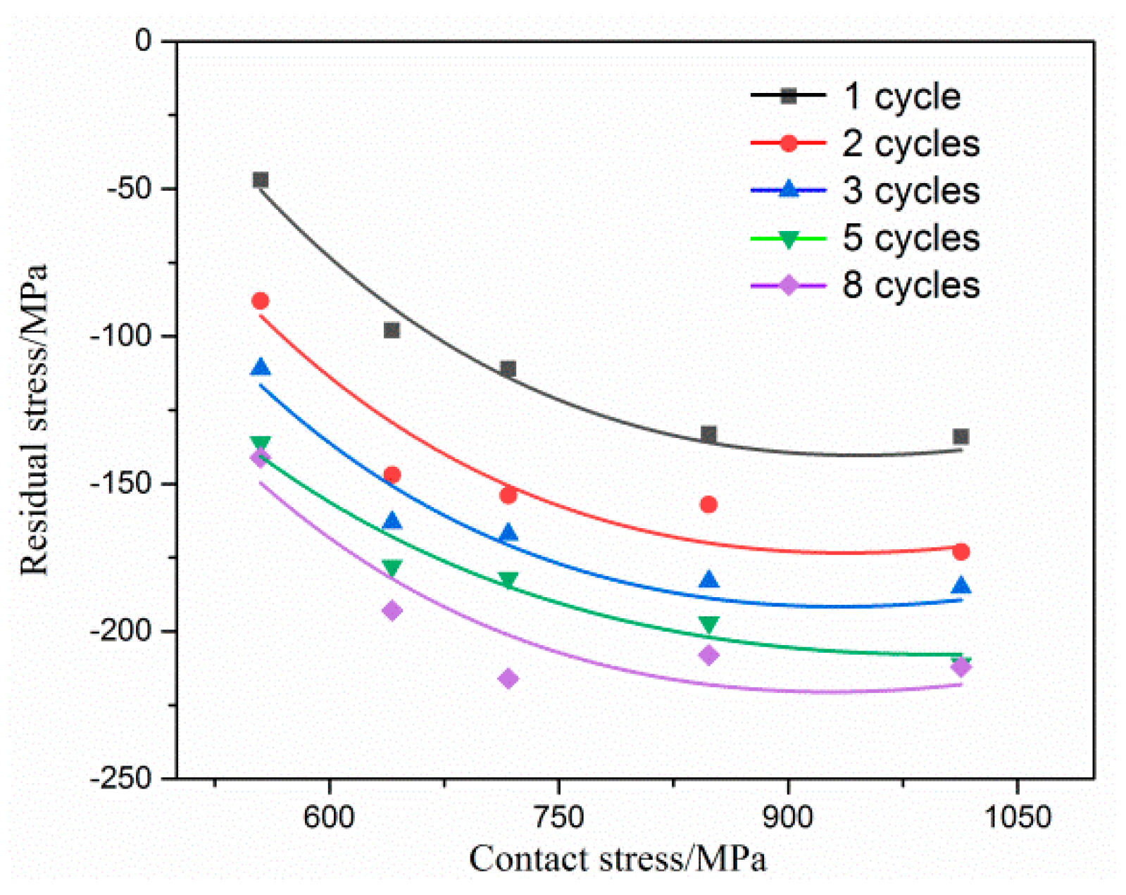
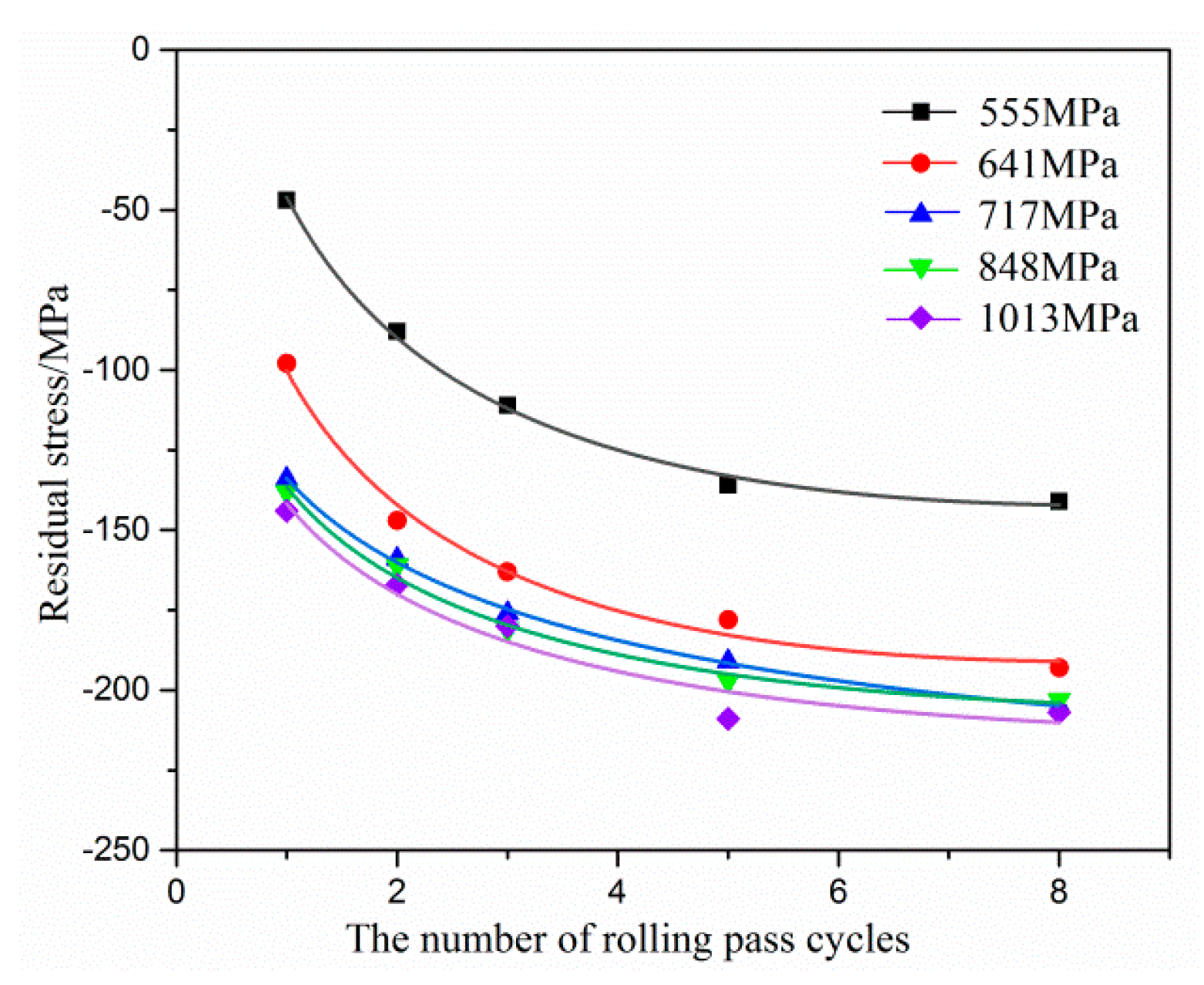
After rolling, the surface residual stress of 210Cr12 specimens has changed significantly, from tensile stress to compressive stress, and with the change of rolling passes and contact stress, there is a certain change rule. The fitting curves of exponential functions between the residual stresses under rolling parameters and contact stresses and rolling passes in Table 2 are established by least square method, respectively, as shown in Figure 4.
It can be seen from Table 2 that after the surface rolling strengthening of 210Cr12 specimen, the surface residual stress has changed significantly, from the residual tensile stress of 52 MPa to the residual compressive stress of −216 MPa. Least square method is used to treat the datum shown in Table 2 in order to illustrate the relation between residual stress’s change and the increase of contact stress or the change of number of rolling pass cycles. Fitting curves of exponential function in Figure 4 resulted from process of datum shown in Table 2 reveal the relationship between residual stresses and contact stresses under each definite number of rolling pass cycles. It can be seen from Figure 4 that the absolute value of residual compressive stress increases first and then tends to be stable with the increase of contact stress during rolling. The absolute value of residual compressive stress increases obviously with the increase of contact stress when the rolling contact stress is below 717 MPa. The absolute value of residual compressive stress increases gradually slowly, and finally close to a certain value with the increase of contact stress when rolling contact stress is over 717 MPa.
Fitting curves of exponential function in Figure 5 resulted from process of datum shown in Table 2 reveal the relationship between residual stresses and the number of rolling pass cycles. It can be seen from Figure 5 that the absolute value of residual pressure stress shows a trend of first increasing and then gradually being stable with the number increase of rolling pass cycles. The absolute value of residual pressure stress increases obviously as the number of rolling pass cycles increases from 1 to 3. With the increase of the number of rolling pass cycles when it is greater than 3, the absolute value of residual pressure stress increases slowly and gradually approaches a certain value.
Taking both rolling process cost and the value of residual compressive stress into account, reasonable rolling process parameters for 210Cr12 in quenched and tempered state within the range of parameter value in our research are contact stress of 717 MPa, rolling pass cycles of 3.
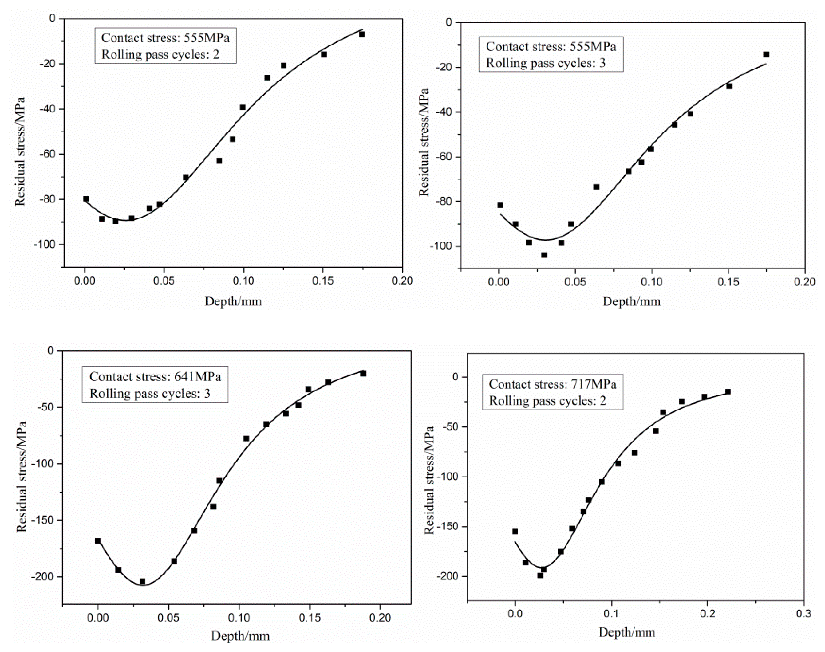
Residual stresses are not uniform from the specimen surface to its interior. In order to investigate the variation trend of residual compressive stress in depth direction, the specimen was cut into 5 × 5 × 10 mm3 pieces. The surface of specimen was corroded layer by layer with chemical etching method in order to measure the residual stress with different depth. The variation trend of residual stress in depth direction has been illustrated as shown in Figure 6. It can be seen from Figure 6 that the absolute value of the residual compressive stress increases first and then decreases with the increase of the depth. The minimum residual compressive stress exists at the position beneath specimen surface at about 0.025 mm. It can be seen from Figure 6 that the depth of residual stress layer is about 0.2 mm.

3.2. Effect of Rolling on Surface Microhardness

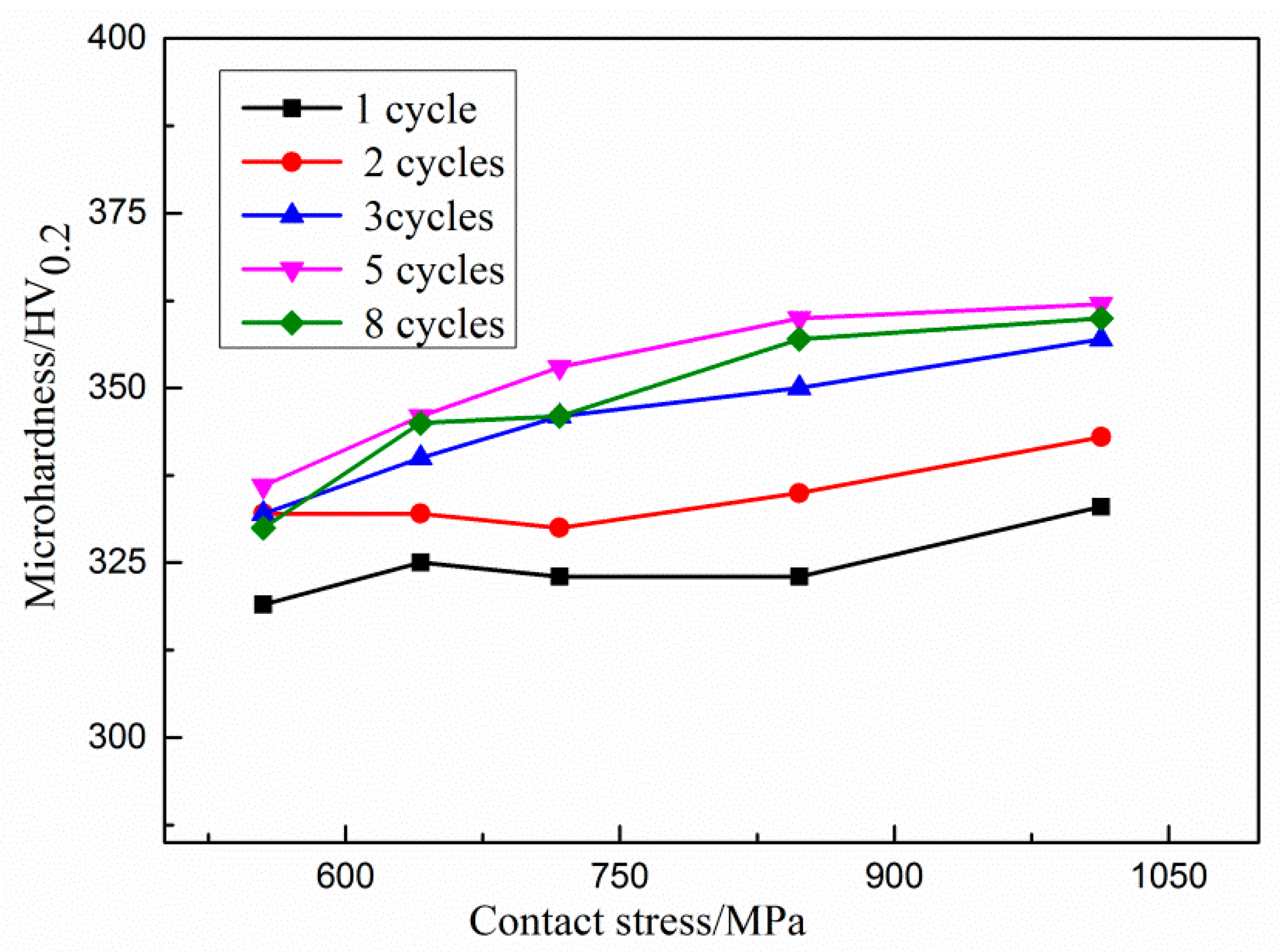
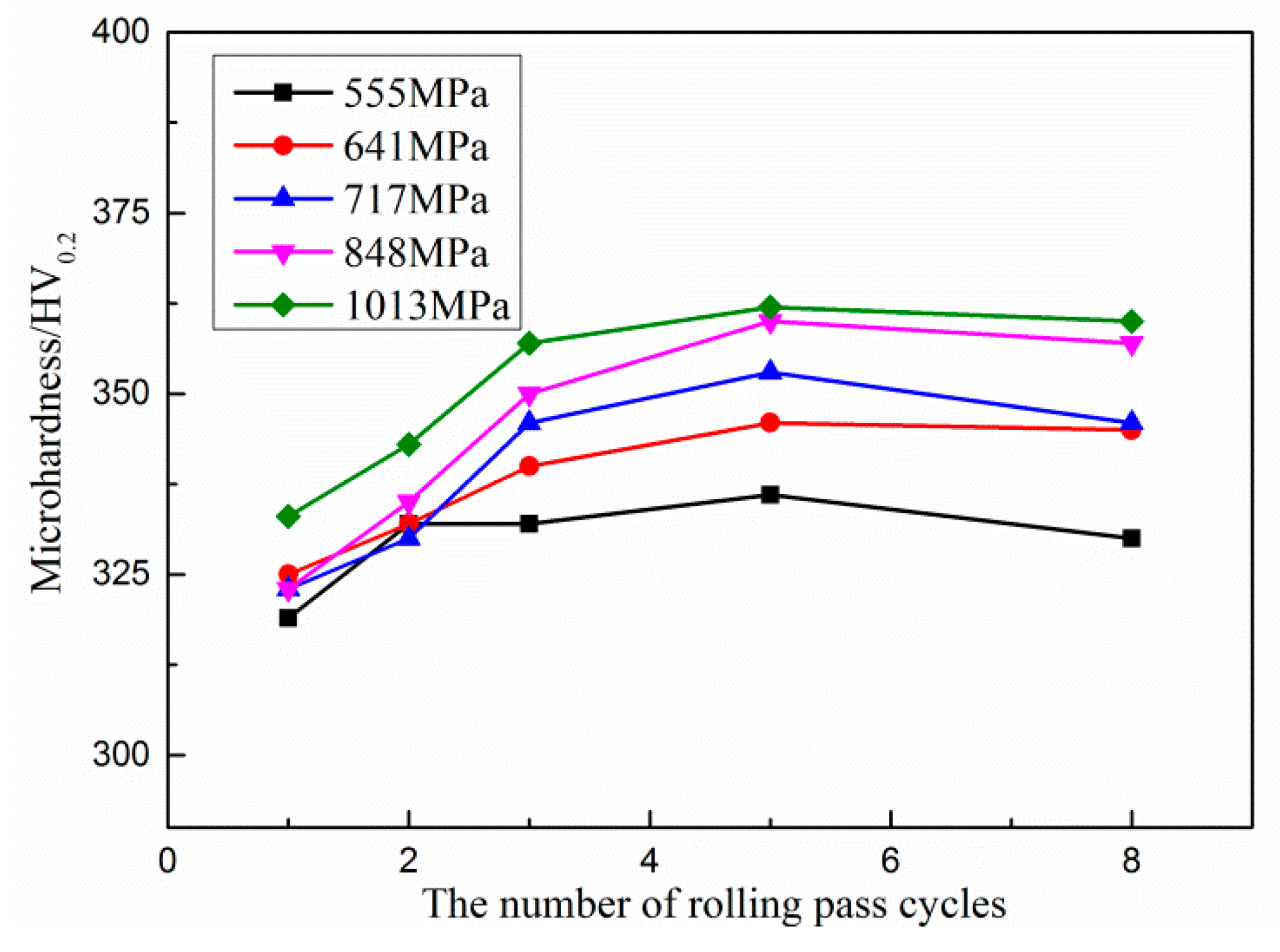
The surface microhardness of the rolled specimens was measured by a digital microhardness tester. The load was set as 200 g for microhardness test of rolled surface. The surface microhardness of specimen before rolling is 270HV0.2. The surface microhardness values of specimens rolled with different rolling parameter is shown in Table 3. It can be seen from Table 3 that the surface microhardness of rolled specimen has been improved from 270 HV0.2 up to 360 HV0.2.
Figure 7 shows the changing trend of microhardness, it can be seen from Figure 7 that microhardness of rolled specimen increases monotonously, but not much, with the increasing of contact stress. It can also be seen from Figure 7 that curves for 1 and 2 cycles does not seems similar to the rest of the curves, that is because, at the beginning of the rolling, the applied force smooths out the irregularities of the surface by forcing the metal to spread and flow plastically from the peaks of the asperities to fill the valleys, after rolling the surface were charged, so the curves for 1 and 2 cycles do not seems similar to the rest of the curves.
Figure 8 shows the changing trend of microhardness, it can be seen from Figure 8 that under different contact stresses, with the increase of rolling passes, the microhardness of the surface of the specimen shows a trend of first increasing and then becoming stable; when the rolling passes are fewer than 3 times, the microhardness increases obviously, when the rolling passes reach 3, the microhardness increases slowly and gradually approaches a certain value. Reasonable rolling process parameters for 210Cr12 in quenched and tempered state within the range of parameter value in our research are contact stress of 848 MPa and rolling pass cycles of 3 as taking both rolling process cost and surface microhardness into account.

3.3. Effect of Rolling on Surface Roughness

Surface topography can be changed because of specimen surface layer elastic–plastic deformation which is resulted from press force exerted by roller—i.e., the value of surface roughness may be changed in rolling process—if press force is great enough. What degree change will happen depends on the surface topography of roller, the value of press force, the number of rolling pass cycles, and so on. Roller used in our research has the characteristics of smooth surface, so the surface roughness of specimen surface will be reduced some degree during rolling process.
Mitutoyo sj-410 surface roughness tester was used to measure specimen surface roughness value Ra, the specimen was cut into 6 × 3 × 5 mm3 piece, the evaluation length was 2.5 mm. The surface roughness value Ra of unrolled specimen is of 3.079 μm, and the surface roughness Ra of roller is of 0.413 μm. The datum of rolled specimens surface roughness are shown in Table 4.
Figure 9a,b show the changing trend of surface roughness. It follows from the surface roughness curves that the surface roughness Ra decreases with the increase of rolling parameters (both contact stress and the number of rolling pass cycles), especially when the contact stress is 1013 MPa. The minimum surface roughness Ra reaches 1.019 μm, and the roughness decreases up to 67%.

4. Conclusions

If the press force exerted on specimen surface is great enough during the rolling process, surface layer material will deform plastically. Meanwhile, grain refinement, dislocation configuration change, or phase change in surface layer material may occur, so that surface material mechanical properties can be changed by means of rolling process. Our rolling test results for 210Cr12 shaft (initial residual stress on the specimen surface was tensile stress of 52 MPa, and initial Ra of unrolled specimen is of 3.079 μm) shows that: (1) Surface residual stress changes significantly from the residual tensile stress of 52 MPa to the residual compressive stress −216 MPa after rolling process for 210Cr12 shaft. (2) The absolute value of residual compressive stress increases obviously with the increase of contact stress as the rolling contact stress is lower than 717 MPa. The absolute value of residual compressive stress increases gradually slowly, and finally close to a certain value with the increase of contact stress when rolling contact stress is over 717 MPa. (3) The absolute value of residual pressure stress increases obviously as the number of rolling pass cycles increases from 1 to 3. With the increase of the number of rolling pass cycles when it is greater than 3, the absolute value of residual pressure stress increases slowly and gradually approaches a certain value. (4) The absolute value of the residual compressive stress increases first and then decreases with the increase of the depth. The minimum residual compressive stress exists at the position beneath specimen surface about 0.025 mm. The depth of residual stress layer is about 0.2 mm. (5) Rolling process can effectively improve the surface microhardness of the specimen. Microhardness of rolled specimen increases within small range monotonously with the increasing of contact stress. Microhardness of rolled specimens shows a trend of first increasing and then becoming stable with the increase of rolling passes. (6) Ra decreases with the increase of rolling parameters (both contact stress and the number of rolling pass cycles). The minimum surface roughness Ra reaches 1.019μm, and the roughness decreases up to 67%. (7) Considering the effect of rolling strengthening such as residual stress, surface roughness, and microhardness, the reasonable rolling process parameters should be contact stress of 700−800MPa, the number of rolling pass cycles not larger than 3, when rolling process parameters including roller’s dimension, spindle speed, and feeding rate are as same as what was mentioned in our investigation. (8) Future work is to investigate the surface microstructures of the rolled surface at different contact stresses and number of rolling passes.

Author Contributions

Conceptualization, P.G.; methodology, Y.Q. and H.C.; validation, P.G.; formal analysis, Y.Q. and H.C.; investigation, K.Q.; writing—original draft preparation, Y.Q.; writing—review and editing, H.C.; supervision, P.G.; project administration, Y.Q. and H.C.; funding acquisition, P.G. and Y.Q. All authors have read and agreed to the published version of the manuscript.

Funding

This research was funded by Shandong Provincial Key Research and Development Program (Grant Nos. 2018JMRH0502, 2019GGX104096), Shandong Provincial Natural Science Foundation (Grant No. ZR2019QEE032) and a project of Shandong Province Higher Educational Youth Innovation Science and Technology Program (Grant No. 2019KJB021).

Conflicts of Interest

The authors declare no conflicts of interest.

References

  1. Priyadarsini, C.; Ramana, V.V.; Prabha, K.A.; Swetha, S. A review on ball, roller, low plasticity burnishing process. Mater. Today Proc. 2019, 18, 5087–5099. [Google Scholar] [CrossRef]
  2. Tang, J.; Luo, H.Y.; Zhang, Y.B. Enhancing the surface integrity and corrosion resistance of Ti-6Al-4V titanium alloy through cryogenic burnishing. Int. J. Adv. Manuf. Technol. 2017, 88, 2785–2793. [Google Scholar] [CrossRef]
  3. Swirad, S.; Wdowik, R. Determining the effect of ball burnishing parameters on surface roughness using the Taguchi method. Procedia Manuf. 2019, 34, 287–292. [Google Scholar] [CrossRef]
  4. Stöckmann, R.; Putz, M. Modelling of surface formation mechanism during burnishing of aluminium. Procedia CIRP 2019, 82, 450–454. [Google Scholar] [CrossRef]
  5. Teimouri, R.; Amini, S.; Bami, A.B. Evaluation of optimized surface properties and residual stress in ultrasonic assisted ball burnishing of AA6061-T6. Measurement 2018, 116, 129–139. [Google Scholar] [CrossRef]
  6. Abuzaid, W.Z.; Sehitoglu, H.; Lambros, J. Localisation of plastic strain at the microstructurlal level in Hastelloy X subjected to monotonic, fatigue, and creep loading: The role of grain boundaries and slip transmission. Mater. High Temp. 2016, 33, 384–400. [Google Scholar] [CrossRef]
  7. Saldaña-Robles, A.; Plascencia-Mora, H.; Aguilera-Gómez, E.; Saldaña-Robles, A.; Marquez-Herrera, A.; Diosdado-De la Peña, J.A. Influence of ball-burnishing on roughness, hardness and corrosion resistance of AISI 1045 steel. Surf. Coat. Technol. 2018, 339, 191–198. [Google Scholar] [CrossRef]
  8. Dwivedi, S.P.; Sharma, S.; Mishra, R.K. Effects of roller burnishing process parameters on surface roughness of A356/5%SiC composite using response surface methodology. Adv. Manuf. 2014, 2, 303–317. [Google Scholar] [CrossRef] [Green Version]
  9. Juijerm, P.; Altenberger, I. Fatigue behavior of deep rolled Al–Mg–Si–Cu alloy at elevated temperature. Scr. Mater. 2006, 55, 943–946. [Google Scholar] [CrossRef]
  10. Avilés, R.; Albizuri, J.; Rodríguez, A.; De Lacalle, L.L. Influence of low-plasticity ball burnishing on the high-cycle fatigue strength of medium carbon AISI 1045 steel. Int. J. Fatigue 2013, 55, 230–244. [Google Scholar] [CrossRef]
  11. Wong, C.C.; Hartawan, A.; Teo, W.K. Deep cold rolling of features on aero-engine components. Procedia CIRP 2014, 13, 350–354. [Google Scholar] [CrossRef] [Green Version]
  12. Moussa, N.B.; Gharbi, K.; Chaieb, I.; Fredj, N.B. Improvement of AISI 304 austenitic stainless steel low-cycle fatigue life by initial and intermittent deep rolling. Int. J. Adv. Manuf. Technol. 2019, 101, 435–449. [Google Scholar] [CrossRef]
  13. Bouzid, W.; Tsoumarev, O.; Saï, K. An investigation of surface roughness of burnished AISI 1042 steel. Int. J. Adv. Manuf. Technol. 2004, 24, 120–125. [Google Scholar] [CrossRef]
  14. Hiegemann, L.; Weddeling, C.; Khalifa, N.B.; Tekkaya, A.E. Analytical Prediction of Roughness after Ball Burnishing of Thermally Coated Surfaces. Procedia Eng. 2014, 81, 1921–1926. [Google Scholar] [CrossRef]
  15. Korzynski, M. Modeling and experimental validation of the force–surface roughness relation for smoothing burnishing with a spherical tool. Int. J. Mach. Tools Manuf. 2007, 47, 1956–1964. [Google Scholar] [CrossRef]
  16. Zhang, P.; Lindemann, J.; Ding, W.J.; Leyens, C. Effect of roller burnishing on fatigue properties of the hot-rolled Mg–12Gd–3Y magnesium alloy. Mater. Chem. Phys. 2010, 124, 835–840. [Google Scholar] [CrossRef]
  17. Jing, Z.H.A.O.; Wei, X.I.A.; Ning, L.I.; Li, F.L. A gradient nano/micro-structured surface layer on copper induced by severe plasticity roller burnishing. Trans. Nonferrous Met. Soc. China 2014, 24, 441–448. [Google Scholar]
  18. Chen, B.; Zhang, G.; Zhang, L.; Xu, T. A new approach of a gradient nanograined surface layer for Mg-3Al-1Zn alloy induced by SMRGT. Int. J. Adv. Manuf. Technol. 2018, 94, 2659–2665. [Google Scholar] [CrossRef]
  19. Shiou, F.J.; Huang, S.J.; Shih, A.J.; Zhu, J.; Yoshino, M. Fine surface finish of a hardened stainless steel using a new burnishing tool. Procedia Manuf. 2017, 10, 208–217. [Google Scholar] [CrossRef]
  20. López de Lacalle, L.N.; Rodríguez, A.; Lamikiz, A.; Celaya, A.; Alberdi, R. Five-axis machining and burnishing of complex parts for the improvement of surface roughness. Mater. Manuf. Process. 2011, 26, 997–1003. [Google Scholar] [CrossRef]
  21. Meyer, D. Cryogenic deep rolling—An energy based approach for enhanced cold surface hardening. CIRP Ann. Manuf. Technol. 2012, 61, 543–546. [Google Scholar] [CrossRef]
  22. Scheil, J.; Müller, C.; Steitz, M.; Groche, P. Influence of process parameters on surface hardening in hammer peening and deep rolling. Key Eng. Mater. 2013, 554–557, 1819–1827. [Google Scholar] [CrossRef]
  23. Huang, J.; Zhang, K.M.; Jia, Y.F.; Zhang, C.C.; Zhang, X.C.; Ma, X.F.; Tu, S.T. Effect of thermal annealing on the microstructure, mechanical properties and residual stress relaxation of pure titanium after deep rolling treatment. J. Mater. Sci. Technol. 2019, 35, 409–417. [Google Scholar] [CrossRef]
  24. Saalfeld, S.; Oevermann, T.; Niendorf, T.; Scholtes, B. Consequences of deep rolling on the fatigue behavior of steel SAE 1045 at high loading amplitudes. Int. J. Fatigue 2019, 118, 192–201. [Google Scholar] [CrossRef]
  25. Saalfeld, S.; Scholtes, B.; Niendorf, T. On the influence of overloads on the fatigue performance of deep rolled steel SAE 1045. Int. J. Fatigue 2019, 126, 221–230. [Google Scholar] [CrossRef]
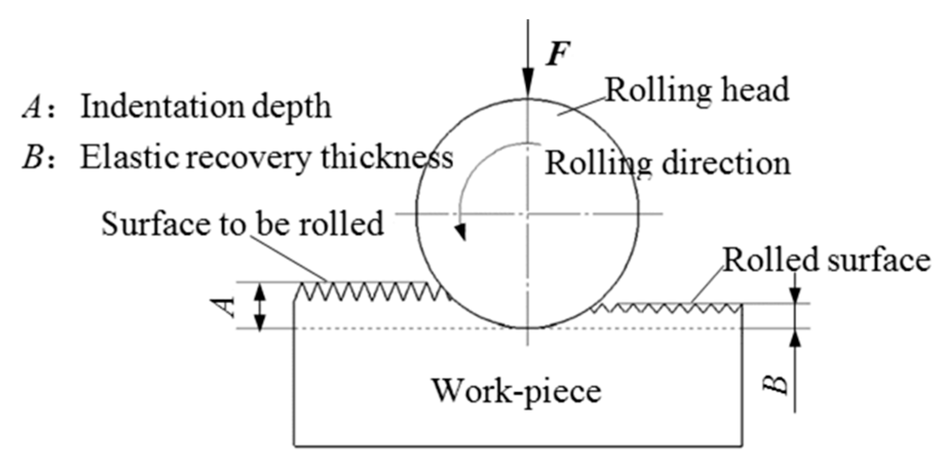
Figure 1. Schematic of rolling process.
Coatings 10 00611 g001
Figure 2. Photograph of the rolling device.
Coatings 10 00611 g002
Figure 3. iXRD stress analyzer.
Coatings 10 00611 g003
Figure 4. Influence of contact stress on residual stress.
Coatings 10 00611 g004
Figure 5. Influence of rolling pass cycle on residual stress.
Coatings 10 00611 g005
Figure 6. Residual stresses in depth direction.
Coatings 10 00611 g006
Figure 7. Influence of contact stress on rolled surface microhardness.
Coatings 10 00611 g007
Figure 8. Influence of pass cycles on rolled surface microhardness.
Coatings 10 00611 g008
Figure 9. Influence of rolling parameters on rolled surface roughness: (a) The variation of the surface roughness with contact stress; (b) The variation of the surface roughness with the number of rolling pass cycles.
Coatings 10 00611 g009
Table 1. Chemical composition of210Cr12
ElementCCrMnSiPSOthers
Weight percentage wt %2.00–2.3011.50–13.00≤0.40≤0.40≤0.030≤0.030≤0.025
Table 2. Surface residual stress data of rolled specimens
Rolling Pass CyclesContact Stress /MPa
5556417178481013
1−47−98−111−133−134
2−88−147−154−157−173
3−111−163−167−183−180
5−136−178−182−197−211
8−141−193−216−205−212
Table 3. Surface microhardness HV0.2.
Contact Stress/MPa5556417178481013
Rolling Pass Cycles
1319325323323333
2332332330335343
3332340346350357
5336346353360362
8330345346357360
Table 4. Values of rolled specimen surface roughness/μm.
Contact Stress/MPa 5556417178481013
Rolling Pass Cycles
12.3262.1022.1812.2692.072
22.2432.2432.2972.0061.572
32.1852.0312.2262.0741.795
52.2112.0192.1761.9541.346
81.942.0012.1241.7691.019