Article

Threading Performance of Different Coatings for High Speed Steel Tapping

by
Alain Gil Del Val
1,*,
Fernando Veiga
1,
Octavio Pereira
2 and
Luis Norberto Lopez De Lacalle
2,3
1
TECNALIA, Basque Research and Technology Alliance (BRTA), Parque Científico, Parque Científico y Tecnológico de Gipuzkoa, E20009 Donostia-San Sebastián, Spain
2
Aeronautics Advanced Manufacturing Center CFAA, E48170 Zamudio, Spain
3
Department of Mechanical Engineering, University of the Basque Country (UPV/EHU), E48013 Bilbao, Spain
*
Author to whom correspondence should be addressed.
Coatings 2020, 10(5), 464; https://doi.org/10.3390/coatings10050464
Submission received: 21 April 2020 / Revised: 6 May 2020 / Accepted: 7 May 2020 / Published: 10 May 2020

Abstract

:
Threading holes using tapping tools is a widely used machining operation in the industry. This manufacturing process involves a great tool immersion in the part, which involves both friction and cutting. This makes the use of coatings critical to improving tool life. Four coatings are used based on Physical vapor deposition (PVD) technology—TiN, TiCN, TiAlN and TiAlN+WC/C are compared to uncoated tool performance. The effect of various coatings on the life of M12 × 1.5 tapping tools during threading of through holes 20 mm deep, in GG25 casting plates, dry and applying cutting speed of 50 m/min. The end-of-life criterion has been established based on a cutting torque of 16 N-m. Taking the uncoated tap as a basis for comparison, it is observed that coatings based on PVD technologies increase tool life doubling in the most advantageous case with the TiAlN coating. PVD type coatings provide better protection to wear at cylindrical area of the tool, where the thread profile is finished, than uncoated taps. The teeth located in the cone-cylinder transition zone of the taps suffer the most wear regardless of the coating. However, taps coated with TiAlN+WC/C wear level values is lowest of all the coatings tested, which indicates a strong reinforcement in these teeth.

1. Introduction

Tapping is a cutting operation, consisting of engraving the profile thread on a previously drilled surface where the diameter obtained is slightly smaller than the thread diameter. This operation is similar to broaching with the difference that in this operation, tool teeth describe a linear path whereas in tapping, the path is helical. The fact that, as in broaching, in tapping each active tooth has different geometry [1] and besides the tool is immersed during cutting in the previous hole, practically without wobbly, makes this operation one of the most complex to analyze. On the other hand, tapping is usually carried out when the workpiece is practically finished and therefore, tapping is an operation of high added value.
As a consequence of the complexity of the operation and the high added value of the workpiece, tapping is a critical operation that should be taken into account. However, there are not many references to this process in the literature, as some authors have pointed out [2]. The high complexity of the tapping operation is one of the main reasons for the relative absence of manuscripts on the topic. Models are not often successful due to this complexity.
Among the problems that can be achieved during the operation, the most important is the breakage of the tap inside the hole. This phenomenon sometimes implies workpiece rejection and then, the resulting increase of manufacturing costs. However, there are cases in which the workpiece can be recovered but in this case the broken tapping tool core must be removed and this operation increases manufacturing time and therefore manufacturing costs. In addition to the problem of tap tool breakage there are other problems such as; breakage of one or more teeth or the inevitable tool wear, which despite being less serious, must also be taken into account to not damage the operation quality.
Although for threading some materials such as abrasive castings, fiberglass, casting steels, austenitic steels and hardened steels, taps are usually carried out with carbide taps, the most commonly substrate used is high-speed steel (HSS) and in particular the obtained by powder metallurgy processes and therefore, the subject of this research.
On the other hand, with the progressive and successful introduction of anti-wear micro-coatings [3,4] most of the HSS tapping tools on the market are coated with very thin films of materials which improve extraordinarily their properties giving them a lower coefficient of friction, a lower capacity of chemical reaction with the workpiece material, a higher resistance to abrasion and a higher hot hardness. In this case, the HSS substrate purpose is to be a robust support and to facilitate a good adherence of the layers. Both properties are essential in the cutting process.
In this research a behavior analysis of three-channel M12 × 1.5 high-speed powdered steel taps is presented. The taps are the main current coatings, which are mentioned in order of appearance on the market—TiN, TiCN, TiAlN and TiAlN+WC/C and are compared with performance of the uncoated tap.
TiN was the first coating applied to cutting tools in the 1970s [5]. This coating has a wide range of uses, being more expensive than the classic coatings (obtained by oxide deposition in a very hot atmosphere) but increasing considerably tap tool life and usually compensates its application. It is one of the first coatings tested on tools, initially on carbide tools and then on HSS ones. This coating is characterized by presenting low friction coefficient that reduces the heat generated during cutting and protects against adhesion and abrasion wear. In fact, after fifty years after its market introduction and despite existing more modern coatings, it is still applied nowadays due to it cheap application. In addition, its gold color reflects tool wear visually, which is useful for the operator with the aim of preventing uncontrolled tap breakage.
The next coating to be applied was TiCN, which has greater hardness and fracture toughness. This last property gives to tool edges resistance to dynamic loads, which makes it very suitable for high-speed and interrupted cutting conditions, where dynamics are always present. Recently, the change produced in the coating materials used and, in the techniques, should be highlighted. In particular, the development of coatings based on Ti, C, N and Al in their various combinations. The incorporation of Al and N gives the coatings better resistance to oxidation and greater hardness when tool is hot. It also reduces residual stresses, thus improving the adhesion of the layer to the core material. Among these new coating techniques, sputtering and “arc deposition” techniques stand out, which achieve “nano” size grain structures that allow graduate the layer composition along its thickness [6]. The most commonly used representative of these new layers in cutting tools in general—and taps in particular—is TiAlN, a material with extraordinary resistance to high temperatures that works very well in the machining of cast iron parts [7], which is the material that is going to be used in this research.
A more recent coating is the coating with lubricating capacity, which consists of depositing layers with a lubricating capacity [8] on the hard layers mentioned above. The most common are CBCs (Carbon based coatings) and among them are DLCs (Diamond like Carbon), WC/Cs (Tungsten carbide/graphite) [9,10] and TiC/Cs. Another kind of lubricant coating is molybdenum sulphide (MoS2), which has been used in space satellite workpieces, where low lubrication conditions are presented due to the vacuum environments, good results are achieved. Regarding CBCs, the WC/C is the one that will be used in this research on a TiAlN substrate.
Despite not being a high number of researches, which deals with tapping operations, several must be taken into account due to its utility. In particular, there are two researches in which Al-Si Alloys are tapped with HSS taps. In particular, in the first one 319 Al-Si alloy was tapped with HSS taps with diamond coatings and uncoated as reference. The use of this coating is due to the high abrasive performances that this kind of alloys. During the tests, MQL lubrication were used. The results shown that coatings are mandatory to achieve a suitable process. On the other hand, the use of MQL (Minimum Quantity Lubrication) was proved beneficial to avoid oil adhesions [11]. Taking into account this last assertion, the other one analyzed the wear mechanisms. In this case, an uncoated HSS taps were used with the aim of enhancing wear on them. The conclusions obtained show that abrasion and adhesion wear caused a severe deterioration of lobes on the chamfered length of the tap [12]. To avoid these wear mechanisms, other research focused on the influence of coating during the tapping process. In particular, tapping operations were carried out with several PVD (Physical Vapor Deposition) coatings on austempered ductile iron (ADI) in Elósegui et al. study [13]. In particular, AlTiN, AlTiSiN and AlCrSiN were tested. The results show that employing drag grinding before coating the taps and better adhesion of the film to the substrate was achieved. On the other hand, forming and cutting taps were used in Pereira and da Silva [14], respectively to tapping lamination carbon steel SAE 1045. In this case, TiCN and TiN coatings were tested. The results show that it is important to take into account the coating layer thickness but it was not discerned which kind of coating or which value thickness were the most robust. This last question was solved in 2019 by in Abdoos et al. [15]. In this research the effect of coating thickness was tested on compacted graphite iron (CGI). In this work, coatings of ≈4 µm, ≈5.38 µm, ≈10 µm, ≈17 µm were tested. The results show that ≈10 µm of thickness is the optimum value to deal with this kind of material. Finally, several tests were carried out by Bezerra and Coelho [16] on cast iron GG25 with taps coated with TiAlN and TiCN. The results show that the main wear mechanism was adhesion followed by abrasion as happened with Al-Si Alloys. Regarding coatings behaviors, at 30 m/min similar performance presented. However, when cutting speed was increased until 60 m/min, TiAlN was the best choice to deal with this cast iron, achieving an increase of tool life near to 60%. Other related works are given by Urbikaín et al. [17] but for forming taps in this case. Other author also analyses the influence of the coatings on diverse tool geometries [18,19,20] analyzing microstructure, mechanical, oxidation and corrosion properties of the Cr-Al-Si-N Coatings [18], the Mo-Cu-V-N composite coatings [19] and the tribological properties, oxidation resistance and turning performance of AlTiN/AlCrSiN multilayer coatings [20].
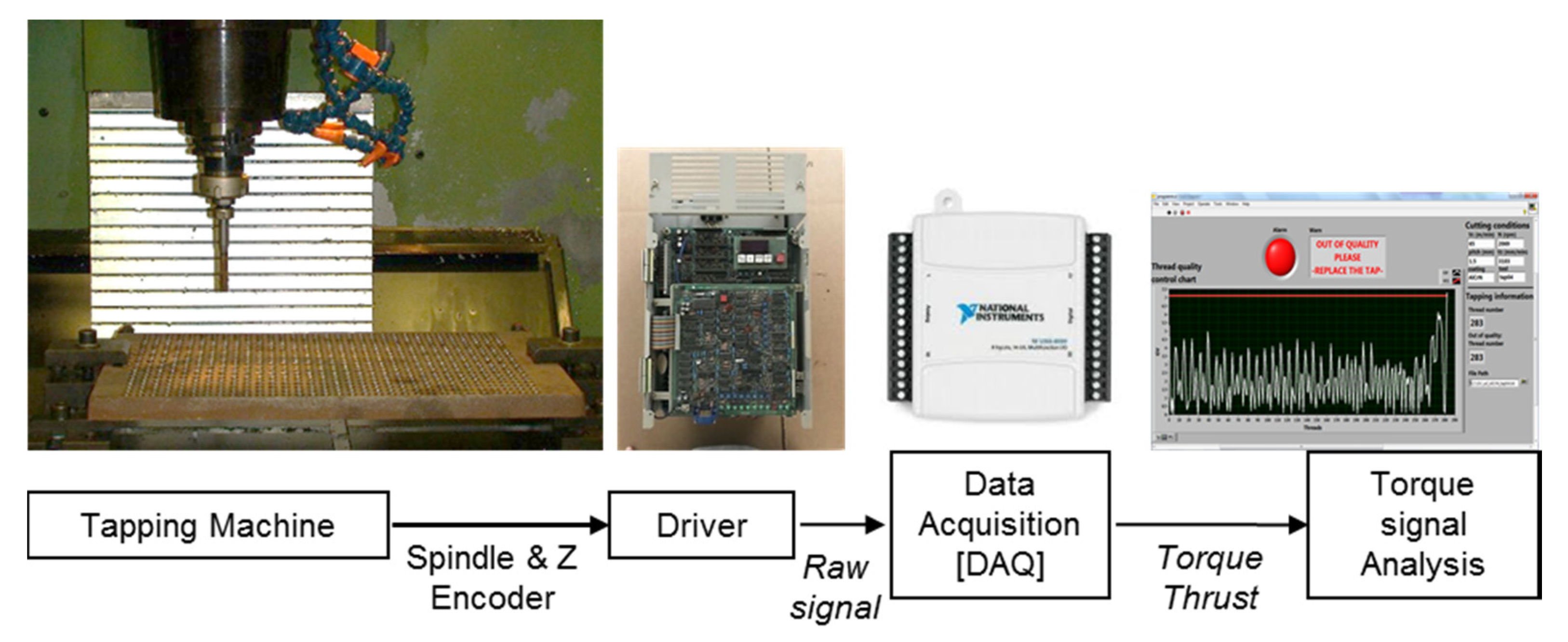
This work aims to have a better understanding of the tap performance comparing some of the existing coatings and it is motivated by the tool supplier NECO-Tivoly Group. Therefore, taking into account all these issues in this work four coatings behavior was analyzed during GG25 cast iron plates. In this case, dry tapping was used in order to enhance which coating presents better lubrication properties and at the same time avoiding the occurrence of adhesive wear. The manuscript was structured the following way—first, the machine setting up where the tapping process was developed, the tap geometry and coating properties are defined (Section 2). Then, the test strategy, wear methodology and the end of life criteria chosen are described. Besides, the results of experimentation and wear analysis are presented (Section 3). Subsequently, the discussion of the results is presented according to the wear, quantitatively evaluated, of the flank face of each of the teeth comparing the behaviors of the different coatings (Section 4) and finally the conclusions are presented.

2. Materials and Methods

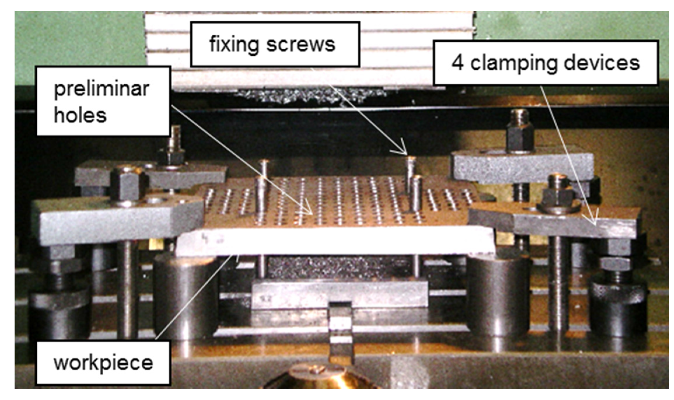
To carry out the tests, a vertical machining center and plates are used in which 2000 holes with a diameter of 10.5 mm were previously drilled by an HSS drill. All holes are inspected by H7 hole plain gauge with “go” & “no-go” checks (min. diam. 10.5 mm and max. diam. 10.518 mm). Figure 1 shows the detail of the tie used to fix and position the perforated plate to the table.
Tapping tools were fixed using a WIDAFLEX UTS tap holder (Fort Mill, SC, USA), Ref. UT40, the bushing was BILZ-M12 (Ostfildern, Germany). Before each test, the tap holder was fixed with a clutch torque of approximately 16 N-m as a safety measure to prevent tap tool breakage inside the hole.
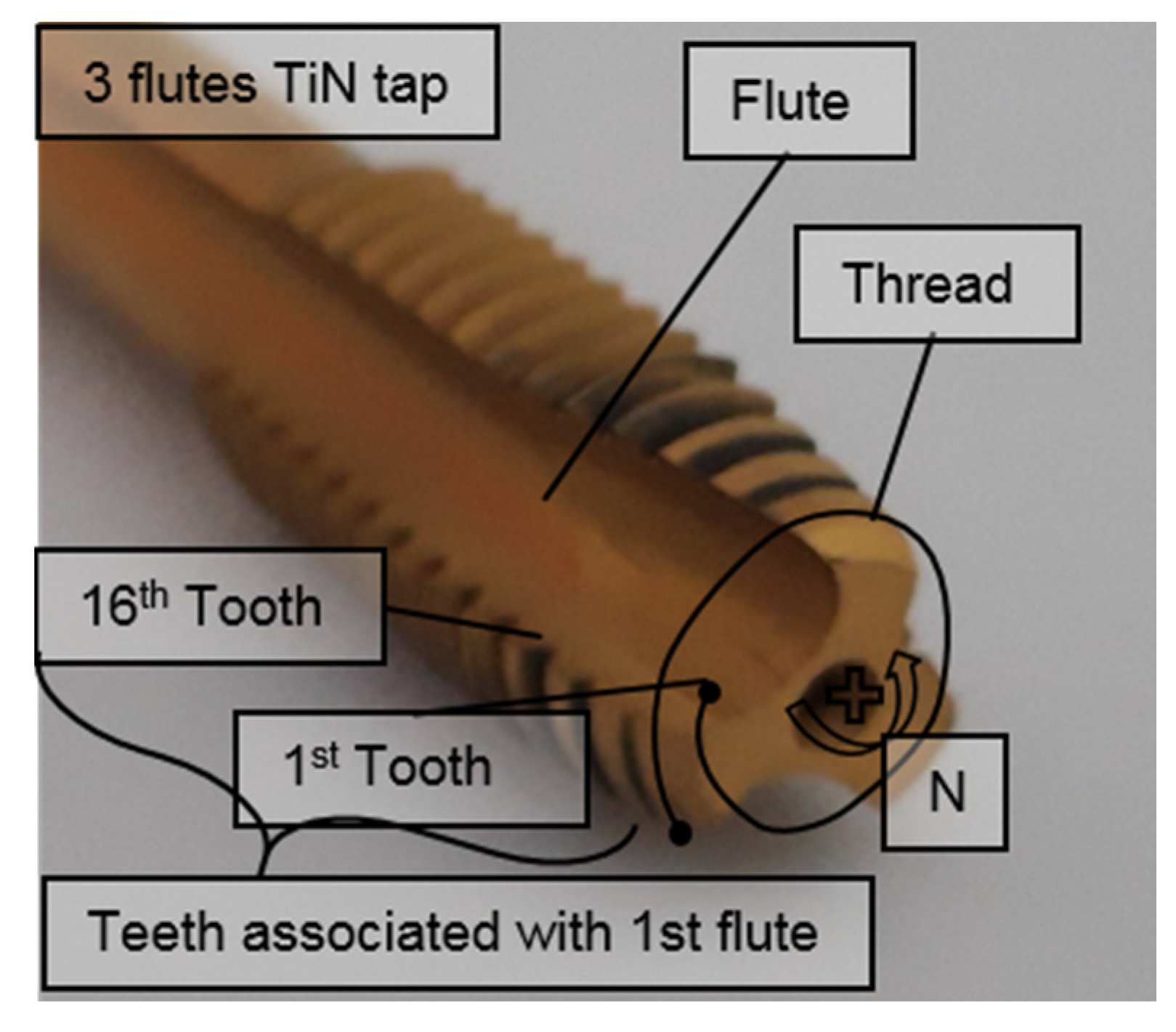
Part material was GG25 cast iron on plates of 250 mm × 225 mm and 20 mm thick on which, as was mentioned, holes with a diameter of 10.5 mm had been previously drilled. The type of tap used was M12×1.5 high speed steel (HSSEE) with a 10° inlet cone half angle and three channels (see Figure 2a). Figure 2b shows an axial view of the tap tool in which the three channels can be distinguished.
The nomenclature used to distinguish the different tap parts (flute, thread, tooth) are shown in Figure 3.
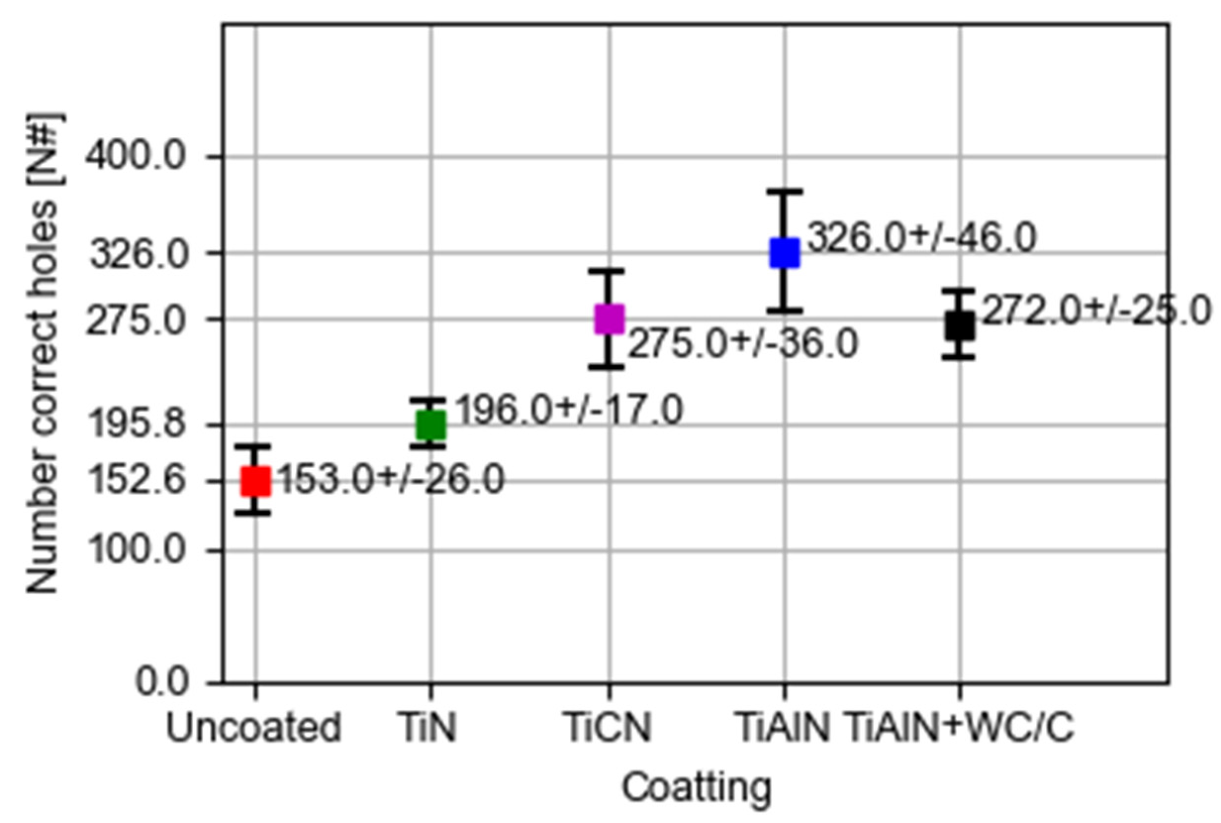
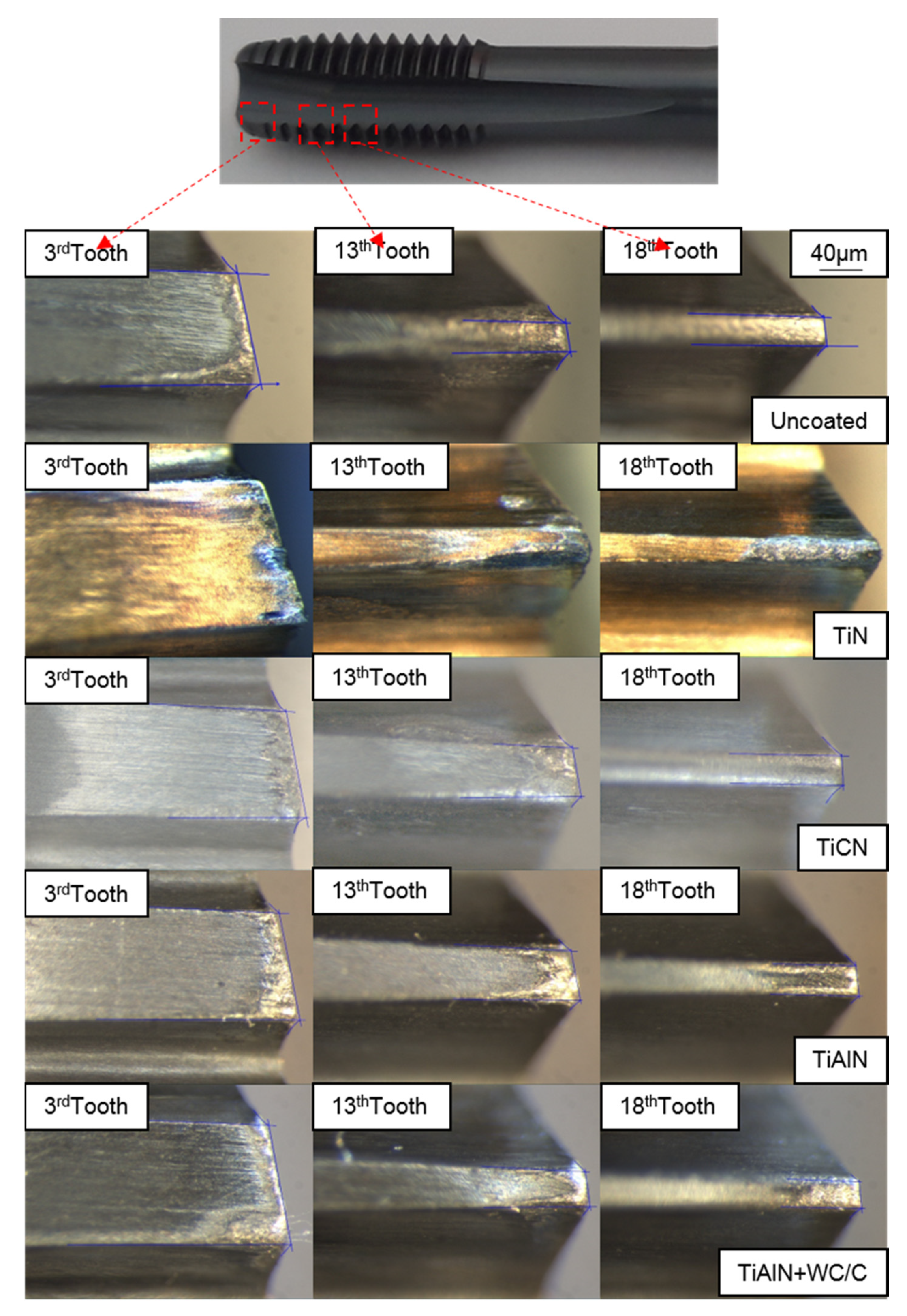
Four coating types (TiN, TiCN, TiAlN, TiAlN+WC/C), as it can be seen on Figure 4, were tested with cutting conditions of Vc = 50m/min and without the use of lubrication. Feed rate is derived from thread metric (M12 × 1.5), threading (tapping) is only one degree of freedom operation, so cutting speed is the master, feed the slave. These cutting conditions, which meet the requirements for productivity of the tool provider and industrial applications, can be considered demanding for this type of machining. This paper seeks to analyze the high-speed machining of iron. Five tap tools have been used for each coating.
Coatings were applied on taps by using PVD technology. The coating supplier used coupons for the Calo test in order to assess coating thickness, along with adhesion by scratch test. Droplets in coating were eliminated by drag grinding several minutes (using OTEC machine (Straubenhardt-Conweiler, Germany). Cutting Edge roundness was also checked, because it implies some variation in performance. Table 1 illustrates the main parameters of coatings.
The coating supplier (Oerlikon Balzers, Antzuola, Spain) measures thickness and microhardness by X-ray fluorescence according to DIN ISO 3497 [21] and ASTM B 568 standards [22] and nanoindentation according to ISO 14577 [23], respectively. Besides, the TiN coating provides a high wear resistance, prevents the cutting edges from being built up because of the cold scrap welding and obtains a higher surface quality of the thread. The TiCN coating has a higher abrasive resistance than previous one and is recommended for tough materials, casting and steels with hardnesses higher than 1000 N/mm2. TiALN has ideal behavior for highly stressed components guarantying the best chip flow. Besides, it is developed to work in dry machining and at higher cutting speed conditions. Finally, the TiALN+WC/C has the same properties as the previous one plus additional lubricant layer to avoid the friction between thread profile and tap tooth.
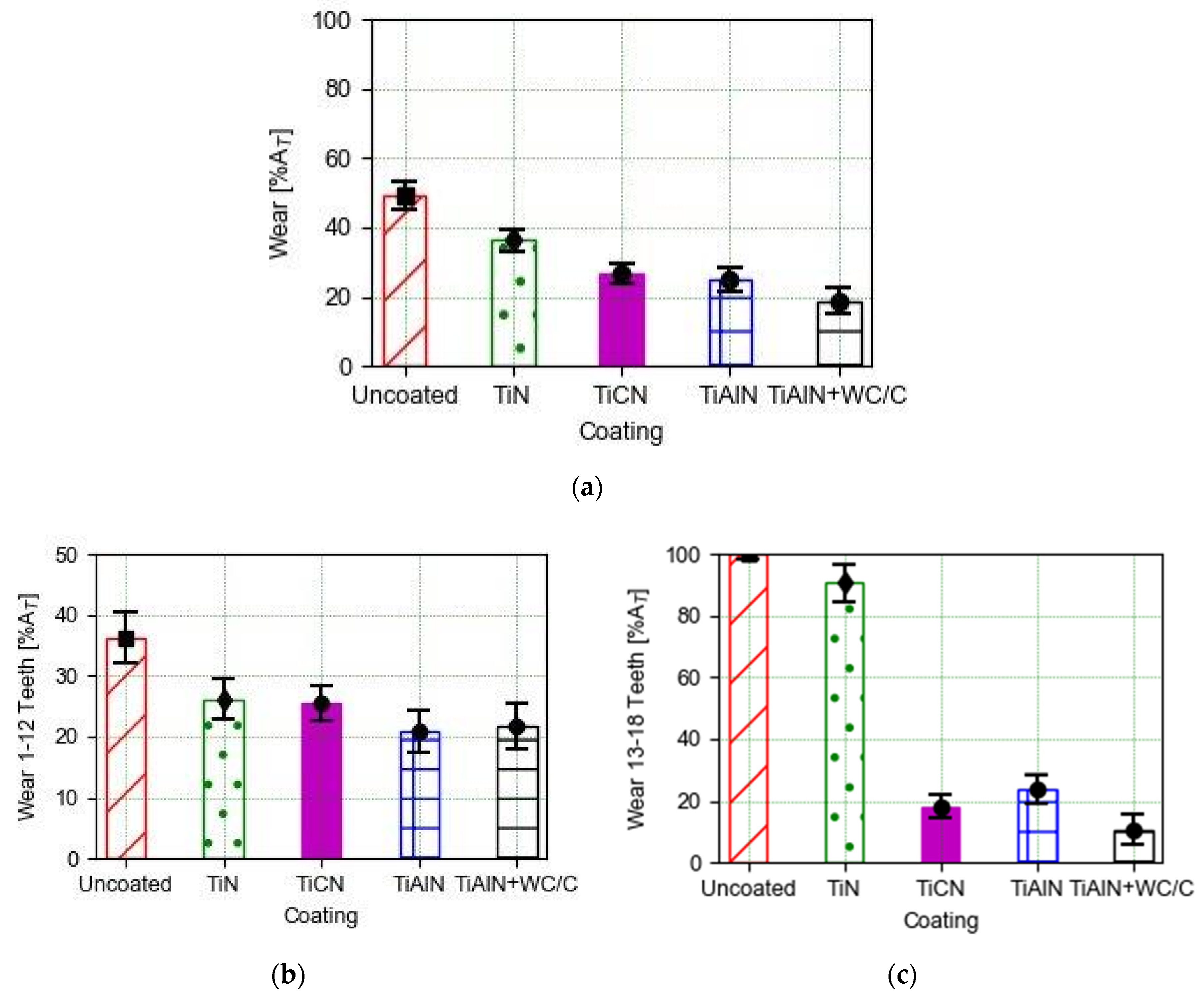
3. Results

3.1. Tool Life Analysis

The measurement ends when the cutting torque exceeds the tared torque (16 N-m). Tool life criteria is settled by the maximum accepted torque, which is mechanically limited by the tool-holder. Therefore, it is not possible to continue carrying out the tests when the torque reaches this limitation. This set-up comes from an industrialization perspective. When this happens, the tap is considered to have reached the end of its life and is removed from the machine and the last two or three holes made are checked with a “GO/NO-GO” thread gauge (which is a cylindrical part with a thread in each terminal, the GO terminal must pass through the threaded hole and the NO-GO terminal must remain out of the hole entrance) to determine the thread quality, in this case 6H. In this work, the “GO” thread gauge does not enter in the thread profile. If the thread quality is in tolerance, the tool life end criterion would go from being marked by the number of the hole in which the tared torque is exceeded, to be the number of the first hole that does not meet the thread gauge test. For example, although the number 3.1 Tap (Table 2) has not exceeded the tared torque to hole 308, its end of life is marked by hole 307 because that hole has not passed the “GO/NO-GO” thread gauge test. The decision to consider that, from this hole, the others did not pass the test either, is based on experience, which indicates that the probability that the threads of the subsequent holes are not correct is very high.
To facilitate the interpretation of the results collected in Table 2, results are grouped by coatings and are represented in Figure 5, where the average life value of each type of coating is observed with the standard deviation. For this, it has been assumed that the tool-life (expressed by the number of threaded holes) is a statistical variable with a normal distribution. TiAlN shows better results in terms of tool life followed by TiCN and TiAlN+WC/C, respectively.

3.2. Torque Signal During Threading Process

Tapping torque measurements were carried out during the threading operation on a vertical CNC machining center , as shown in Figure 6. The monitoring system is essentially a non-intrusive sensor solution. The raw voltage signal from Varispeed-626MTIII CNC machine tool (Johannesburg, South Africa)drive of spindle motor was captured. A data acquisition system belongs to National InstrumentsTM (Austin, TX, USA) and a PC was used to collect the signal to obtain the torque. This current signal is converted using 7.4 N m/V (Yaskawa’s technical information). This calibration was carried out based on previous work [24]. This torque is known to be sensitive to the tap wear status [16,21,22].
The torque diagram on the time domain reflects the mechanical conditions in the thread sculpt generation and also its effectiveness as a monitoring strategy to correlate with tap life. In the threading process, the torque signal has some stages involving the cutting and friction tap teeth. This sequence is shown in Figure 7 and in order to correlate the torque data against the wear phenomena taking place in the threading process, this study selects the main stage called ATAPPING in Figure 7 when tapping a thread and although there are other stages, in the torque signal that are sensitive to the thread quality [25], these ones are less sensitive to the tap wear level. Due to the complexity of the tool tip geometry and the number of tooth/edge actives during the tapping process, the friction coefficient could not be directly calculated using the same methodology of [26].
Focusing on ATAPPING when sculpting the thread, the evolution of torque signal over time can also be divided into three steps, as shown in Figure 8. The scheme of the tap position related to the workpiece is shown at the left side of Figure 8. The different steps are defined as:
  • 1st Step (i → ii)—the first step starts when the tool tip of the first tooth touches the pre-drilled hole and continues until the first cylindrical tooth enters the hole. During this period, torque increases gradually as total cutting areas are active.
  • 2nd Step (ii → iii)—is where the cylindrical and conical teeth are fully engaged in the hole and can be considered as a combination of cutting (conical teeth) and friction/finishing (cylindrical teeth) mechanical phenomena. The toque maintains its value almost continuous. This step finishes when the first conical tooth gets out of the hole.
  • 3rd Step 3 (iii → iv)—the last step where the conical teeth start to come out of the hole and continuously to the point where no cutting or finishing is observed and the tap arrives to the stopping plane. Torque signal reduces progressively until it reaches near zero value. When this step ends the tap stops rotating and starts its travel back with and inverse rotation to the starting point out of the finished threading hole.
Figure 9 illustrates the evolution of the torque in the cutting zone (comprising the three steps previously described) with the number of threads mechanized. The values shown are derived from the calculation of the average torque value for the five taps tested with each coating in 25-hole sections. A similar evolution of the torque is observed in all the coatings tested. It can be inferred that the torque in the first holes when the tool has a non-worn shape has a great variability and, also, mean values. The value of the torque with the TiAlN+WC/C coating is the one that starts from a higher value because the irregularity in the main edges persists until the lubricant layer has homogenized the main edge geometries and before stabilizing the cutting process.
As the cut-off value of the cutting torque was selected 16 N-m, the behavior is analogous in all coatings.
Therefore, the behaviors of the TiN and the uncoated taps the torque (see Figure 9) can be divided into three parts, initially the torque reaches a peak value that decreases in a valley area in which large variations do not seem to be observed and, finally, the torque value increases progressively until reaching the torque threshold.
In relation to the torque evolution in the other coatings tested (TiCN, TiAlN and TiAlN/WC + C), it is observed that in the first threads the variability is greater but not so its average value that presents constant values until reaching a point where these they begin to increase until they reach the maximum limit established. It is interesting to note that in the case of TiAlN/WC+C, higher torque values are used, which significantly affects the life of the tool, which is shortened (Figure 5).

3.3. Wear Behavior Comparing Different Coatings

The procedure consists of observing and measuring the rake and flank faces of the teeth; however, given the small level of wear of the latter, it has been decided to measure only the flank faces.
According to the manufacturer’s data, shown in Figure 2, these taps have between 3.5 and 4 threads in the conical part, that is, between 10.5 and 12 cut teeth. Starting from tooth number 12, the teeth are located in the cylindrical part of the tap, therefore they finish and/or rub the thread profile. It was decided to measure all the cut teeth and some finishing/friction ones until making a total number of 18 teeth. It should be remembered that each section of thread between two neighboring channels is called a tooth (see Figure 3).
To evaluate wear quantitatively, the relative wear parameter %A is defined, which responds to the expression:
% A = A s p A p 100 % ,
where Ap is the area of the flank face of each tooth along the 1 mm length of the thread and Asp is the worn part of Ap as can be seen in Figure 10.
Figure 11 illustrates the wear produced on a finishing/friction tooth of the uncoated tool in which there has been significant flank wear.
Figure 12 shows the wear level on the flank of three teeth of a tap by coating to exemplify the type of wear observed on the tools. The third tooth is presented as representative of the conical part in which the cutting stage occurs. The thirteenth tooth is the last tooth of the transition between the conical and cylindrical parts and the eighteenth tooth is the last cylindrical tooth analyzed that would have a finishing and friction function in the threading process. Finally, a chipping phenomenon is observed as a singular wear mechanism in the third tooth of the tool coated by TiN.
Figure 13a shows the average percentage wear on all the teeth of the different tools tested at the end of their life. The higher percentage of wear is observed on uncoated tools and those that have been coated with TiN, with the standard deviation being the variability of the comparison of the five tools tested by coatingThis total wear is separated in the cut teeth, which are the responsible for carving the thread profile (see Figure 13b) and the finishing ones, which calibrate the thread profile (see Figure 13c).
Discriminating wear in terms of the cutting mechanisms; in the area associated with the removing material, the wear produced is quite similar among coatings with the uncoated taps being the most worn and then the coatings TiN and TiCN, respectively. However, in the finish/friction area, the uncoated and TiN coated taps suffer a greater wear percentage than the other ones. Finally, the TiAlN and TiAlN+WC/C have the lowest levels of wear when the all the teeth of tap are studied. Although the wear levels are similar in the conical part for all the coatings, the wear levels of TiAlN and TiAlN+WC/C have an average of 75% less wear than the reference set value (1 mm).

4. Discussion

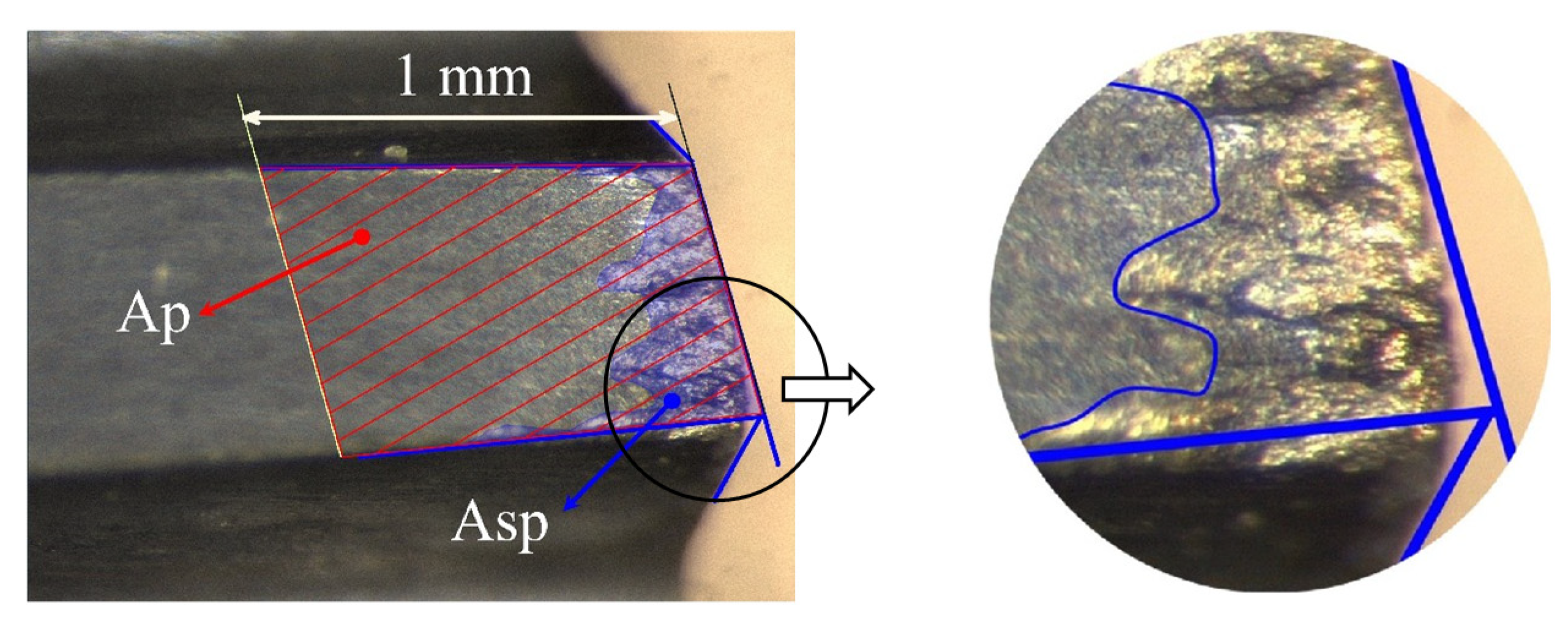
Once experimental results were illustrated and analyzed and, also, the better performance of TiAlN y TiALN+WC/C coatings was observed, the following section—the Discussion—focuses on comparing the wear level of these coatings and without coating from the first tooth to the eighteenth one. Also, results on tool wear on each tooth on TiN and TiCN coatings are addressed. Before starting the discussion, the meaning of thread over the %A profile is defined plastically in Figure 3. However, the thread is the set of three teeth from the first flute to the same flute in a helicoidal movement.

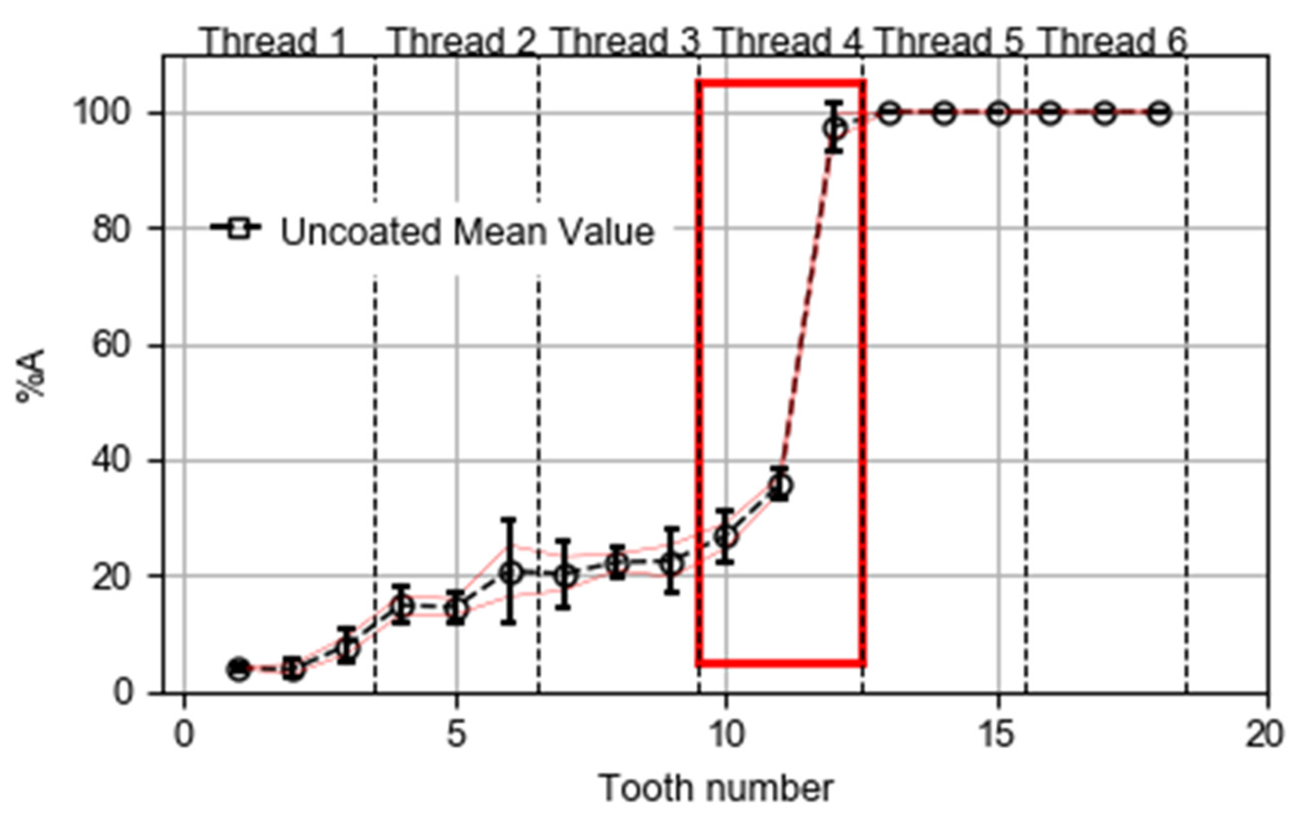
4.1. Discussion of Results on Uncoated Taps

In all taps tested, the cutting teeth are from tooth 1 to tooth 10. From 13, they are in the cylindrical part and therefore are finishing teeth. Regarding tooth numbers 11 and 12, there are three possibilities—(a) teeth 11 and 12 can be cutting tooth and fishing one, respectively, (b) they can be both cutting ones or (c) they can be both finishing. Logically, the probability of being cutting tooth is higher in edge 11 than in tooth 12.
Figure 14 shows the evolution of parameter %A for each tooth from the first one to the eighteenth tooth of the five uncoated taps studied. The behaviors of %A profiles are similar among uncoated taps.
Therefore and to simplify the analysis, Figure 15 illustrates the mean value of %A of these five specimens with a 95% confidence interval.
Focusing on Figure 15, the value of %A remains below 10% in teeth 1, 2 and 3 and it suddenly changes to a value less than 20% in teeth 4 and 5 and it increases up to 20% and remains in the next six teeth (5 to 10). Tooth 11 exhibits slightly more wear than 30% and tooth 12 rises to a value of 100%. Assuming, as it seems logical, that in the five uncoated taps tested, tooth 11 is a cutting one (since it maintains the wear values of the previous ones). Taking into account the finishing thread profile of tooth 12, an explanation of the high wear value of the tooth 12 can be a consequence of the wear on the flank face suffered by tooth number 11, which leaves the thread profile unfinished and, therefore, tooth 12 removes the uncut material. This one, like the rest of the friction teeth, suffers heavy wear at its two corners and as its main edge is very small (1/8 of the step, that is, 0.18 mm), the wear of both corners (see Figure 11) overlap generating a high relative wear value on the clearance face. As tooth 12 wears out, it leaves the thread profile unfinished and, consequently, tooth 13 becomes cutting edge. This wear is propagated along the friction teeth being responsible for calibrating the thread.
Despite the 100% wear value of teeth 12–18, the threads generated by the uncoated taps were inspected by the “GO/NO-GO” thread gauge and all threads are in tolerances. Although the wear parameter %A is 100%, the amount of material without removing it from the thread profile is small enough not to prevent the threaded hole from allowing the thread gauge to enter. Consequently, teeth 12–18 clearance faces of uncoated taps have higher wear levels than the other coated ones. However, the wear is shallow and, consequently, the threads are correct.
This mean wear profile of uncoated taps is the basis wear profile for comparing with the other coated ones. Besides, and as mentioned before, the TiAlN and TiAlN+WC/C were selected to discuss the wear results because they have the minimum wear levels as it was described in Section 3.

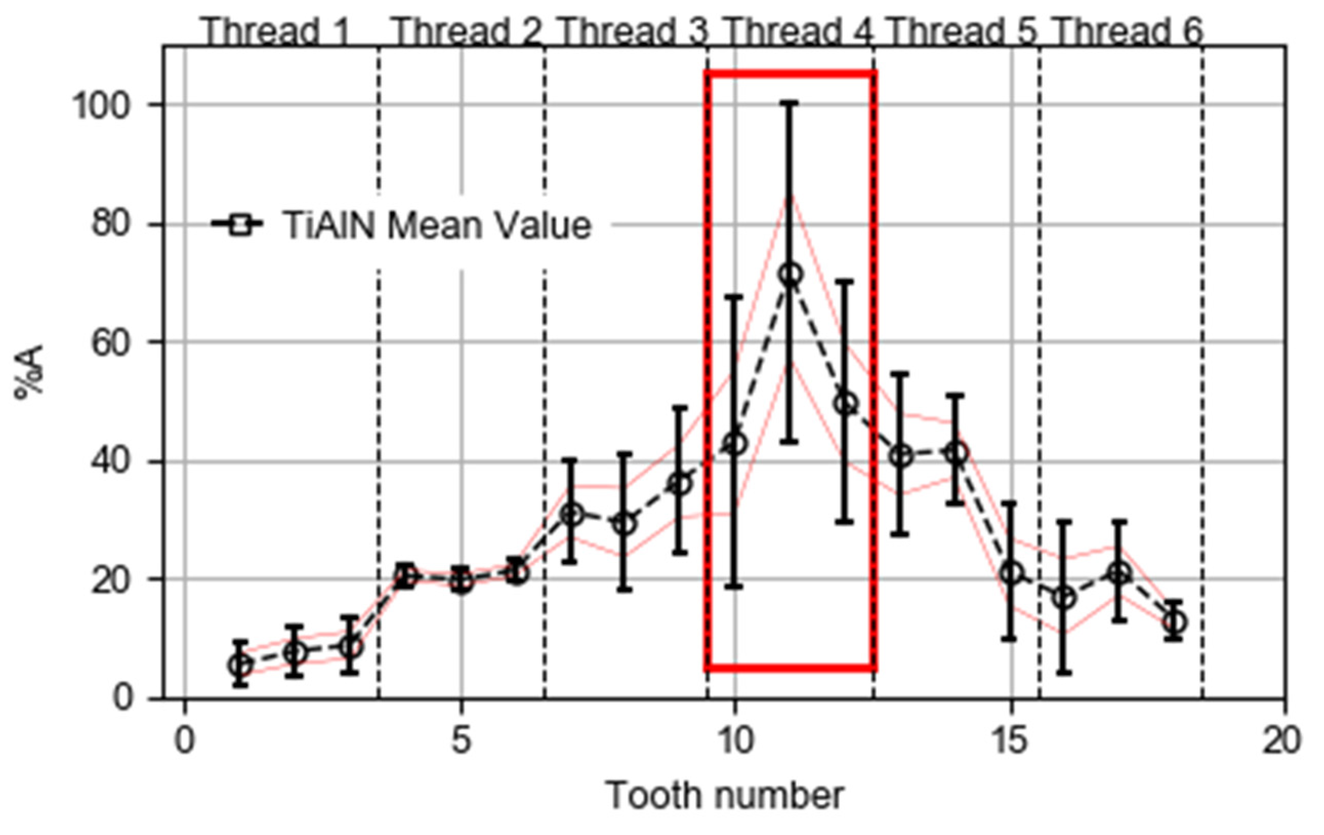
4.2. Discussion of Results on TiAlN Coated Taps

Figure 16 illustrates the different behaviors of %A parameter for each tooth. Observing the similar wear shapes of all taps, the average wear profile is calculated to simplify the results.
Therefore, Figure 10 shows the average %A values of five taps with a 95% confidence interval.
Taking into account the wear profile values of uncoated taps in Figure 15, Figure 17 shows a similar behavior till the sixth tooth comparing with Figure 15 because the average wear levels of teeth 1, 2, and 3 are close to the 10%, then the wear level increases up to 20% in tooth 4 and, finally, this value is maintained in teeth 5 and 6. Therefore, this behavior is similar in both taps. The same does not happen with the dispersion values that are clearly lower than those of the uncoated ones, observed in Figure 15, especially those corresponding to thread 2. Continuing with the analysis, it is observed that between tooth 6 and 7 another increase happens until reaching a value greater than 30% and this value is maintained in tooth 8. In teeth 9 and 10, the values reach 35% and 40%, respectively. Therefore, the conical part of tap has roughly the same wear level independent of coating as can be seen in Figure 13b.
In the conical-cylindrical part, the wear percentage reaches 40%, more than 50% and a maximum value of 65% in teeth 10, 11, and 12, respectively. Therefore, the increases are 30% and 25% from teeth 9 to 12 and from teeth 10 to 12, respectively. For these same uncoated teeth, the same parameter soared the value of 20%, 25%, and 100% in teeth 9, 10, and 12, respectively (see Figure 15). That is, in the same interval of teeth, it presented increases of 80% and 75%, respectively, values much higher than those of 30% and 25% of TiAlN. Consequently, the TiAlN coating prevents the development of strong wear gradients detected in the uncoated taps.
On the other hand, this coating prevention on the finishing teeth is maintained along the cylindrical part of the tool because wear begins to decrease, more or less with the same slope with which it had been increasing and dispersions also decrease with respect to those of teeth 10, 11, and 12. In all uncoated teeth show a wear percentage of 100% and their dispersions are null because the Asp wear areas on these teeth are always higher than the Ap control area. It does not make sense therefore compare both coatings from edge 12 onwards.
However, the dispersion corresponding to the uncoating is much less than TiAlN coated taps (as can be seen by comparing Figure 15 and Figure 17). This strong dispersion implies a low reliability of the TiAlN coating, a problem well known to manufacturers of coated tools. This worse reliability is due to the high dispersion of the life values of the taps (Table 2), to the influence through the decrease of %A values from teeth 12 to 18 and to the gradients in the tap border teeth. Finally, there is also a striking low correlation between the number of threaded holes at the end of life and the overall wear area (At) of the taps (area under the curve %A-number of teeth), in other words, equal taps (of the same coatings) present, at the end of life, some quite different overall wear levels(see 1.3 versus 4.3 in Table 2 and Figure 15 and Figure 17, respectively).

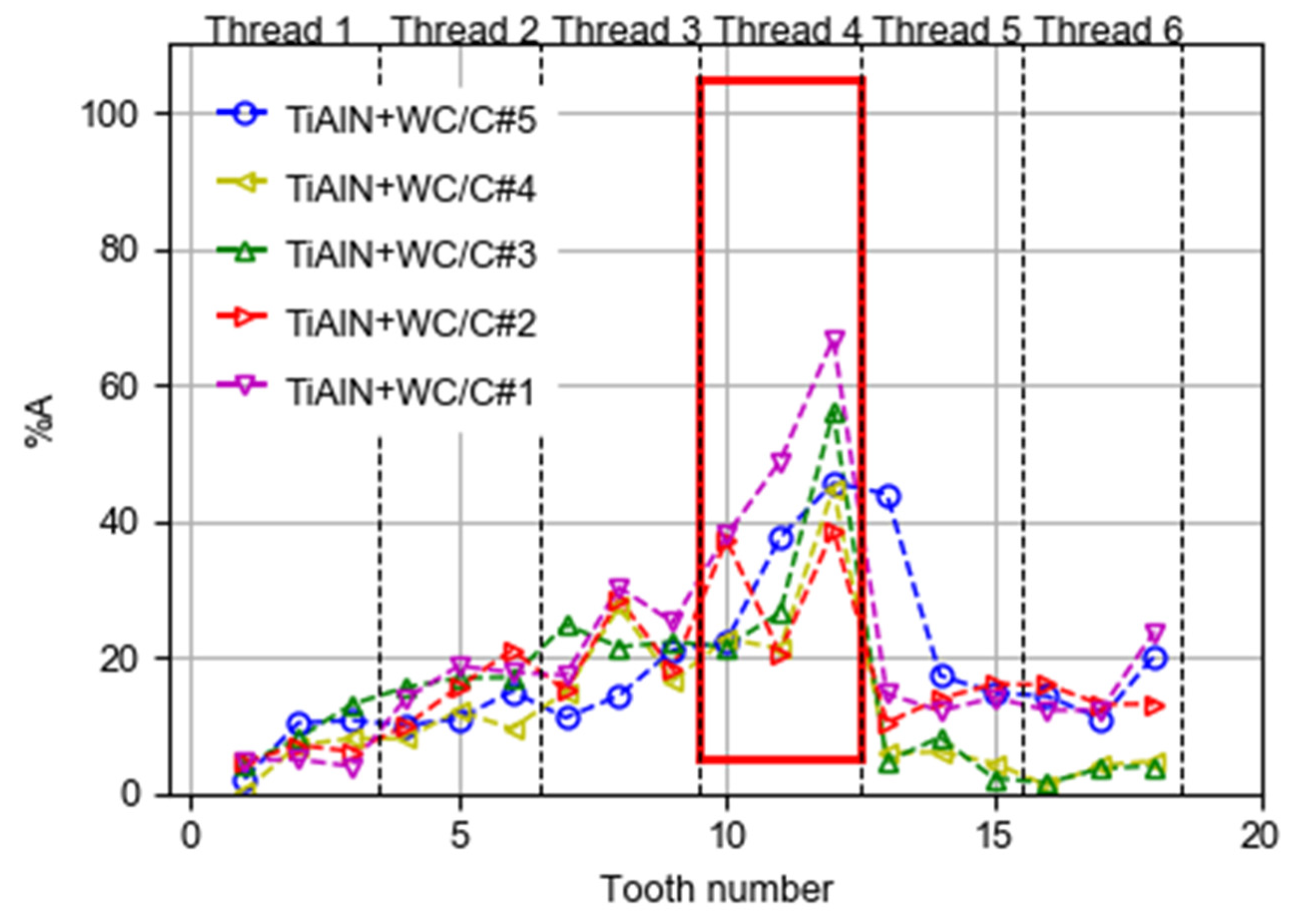
4.3. Discussion of Results on TiAlN+WC/C Coated Taps

Figure 11 illustrates the %A parameter evolution for each tooth from the first tooth to the eighteenth one of the five taps studied.
Before starting the discussion of TiAlN+WC/C taps, the wear profiles of this coating are like previous ones. Therefore, the discussion is reasonably equal to the previous section when comparing this coating tap with uncoated one. This part focuses the study on comparing this coating with the previous one being the best tap tool according to the tool life and wear level.
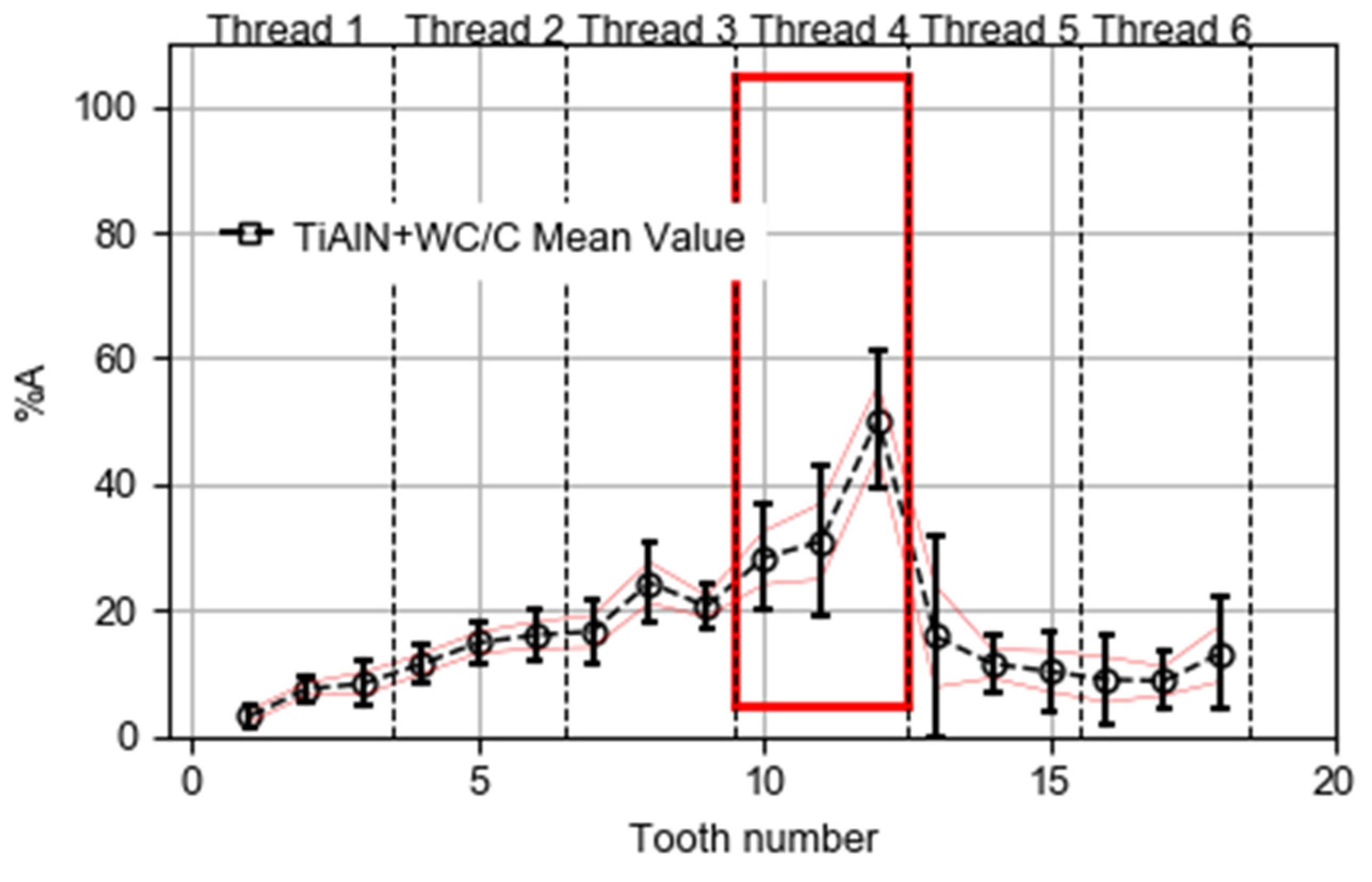
To simplify the analysis, Figure 18 shows the %A average value of five tools with a 95% confidence interval.
As seen previously, the TiAlN+WC/C coating is, a priori, superior to the TiAlN, due to the addition of a WC/C layer that acts as a lubricant and to assess this superiority [10], both will be compared below.
Firstly, an impressive difference is observed in behavior observing Table 2, consequently, both types of taps reach the end of life defined by the torque value of 16 N-m having made a very different number of holes 272 and 326 coated with TiAlN+WC/C and TiAlN, respectively. This result states the addition of a layer of solid WC/C lubricant not only does not improve but also worsens the life of the tap and, consequently, this result contradicts the purpose that is sought with the contribution of the layer.
However, from the observation of Figure 17 and Figure 19, it is concluded that the average and dispersion of the %A values of the TiAlN coating are much higher than TiAlN+WC/C one because the first one presents has not got the lubricant layer. This wear decrement is lower at edges seven through thirteen and, specially, at finishing teeth (cylindrical part).
Finally, the WC/C moves the maximum one tooth reduces the maximum peak of wear in 30%. Besides, the wear propagation is less in this coating along the finishing teeth.

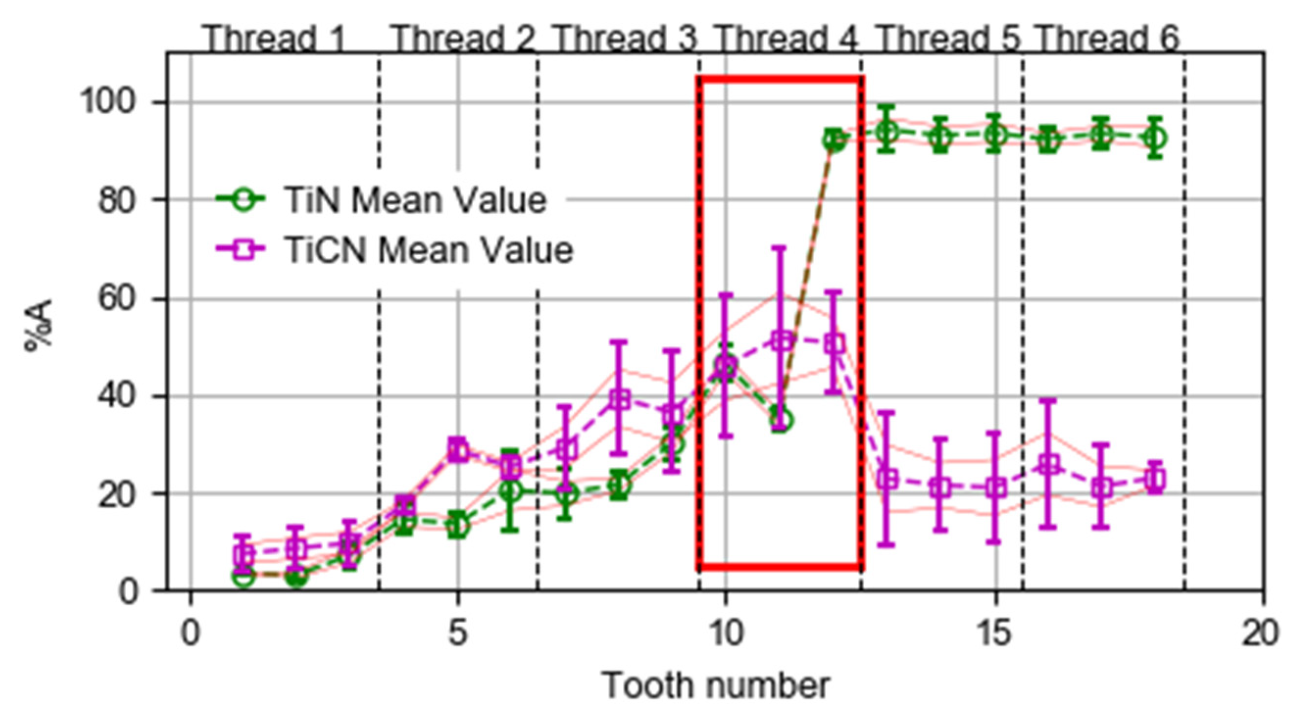
4.4. Discussion of Results on TiN and TiCN Coated Taps

In this subchapter a review of the results of mean wear area percentage %A on TiCN and TiN coating taps is address. Figure 20 shows the wear of the different tap tooth at the end of the tool life one it reaches the end of life criterion. The mean value of the 5 taps on TiCN and the 5 taps on TiN is shown. The wear behavior on the TiN taps is similar to the one observed on the uncoated tools (Figure 15) but the 100% of wear is not observed at the cylindrical teeth. On the other hand, TiCN tools shown values closer to the ones observed at the TiAlN and TiAlN+WC/C as it can be concluded comparing Figure 17 and Figure 19 and Figure 20.

5. Conclusions

This paper presents the results of the comparison of four different coatings (uncoating, TiN, TiCN, TiAlN and TiAlN/WC+C) for high-speed iron GG25 threading. From this work, the following conclusions are drawn from the comparison:
  • Tool life, based on the number of holes made before exceeding the maximum allowable torque, allows establishing that the TiAlN coating is the best alternative. It is observed that both TiCN and TiAlN/WC+C have a similar behavior, this being 30% better than that observed with more classic coatings such as TiN or uncoated tap.
  • From the analysis of the torque during the cutting stage, similar values and evolutions are observed in all the taps, with an increasing from 9 N-m to 16 N-m, approximately. A higher initial torque value is observed in the case of TiAlN/WC+C, which contributes to shortening tool life that was conditioned to a fix torque limit for every tap. This higher value is due to the irregularity in the main edges in the initial threads before being stabilized the cutting process when the lubricant layer has been homogenized along the main edges.
  • Focusing on wear level, teeth flank wear was analyzed, showing greater wear in the tools without coating and with TiN coating specially in cylindrical part (finishing teeth). This fact confirms a high correlation between wear and the number of threads carried out during tool life. The rest of coatings (TiCN, TiAlN and TiAlN+WC/C) improves the wear levels in the conical-cylindrical part and, specially, in the finishing teeth (cylindrical part).
  • The wear at the conical part (cutting teeth 1–9) of the tool on TiAlN and TiAlN/WC+C coated tools are quite similar to the uncoated ones (average wear difference is 15%). However, the %A wear percentages of the TiAlN (75%) and TiAlN/WC+C (90%) taps are much lower than those corresponding to uncoated ones (100%) in the cylindrical part (finishing teeth). Then, it can be concluded that the TiAlN and TiAlN/WC+C coatings fundamentally benefit the performance in the friction and finishing part of the tap profile.
  • The lubricant layer (WC/C) reduces wear level on flank faces and improves the cutting performance on the teeth in the conical-cylindrical part of the tap tool.

Author Contributions

Conceptualization, A.G.D.V. and F.V.; methodology, A.G.D.V. and F.V.; validation, A.G.D.V. and F.V.; data curation, A.G.D.V. and F.V.; writing—original draft preparation, A.G.D.V, O.P., and F.V.; writing—review and editing, L.N.L.D.L.; supervision, A.G.D.V. and L.N.L.D.L.; All authors have read and agreed to the published version of the manuscript.

Funding

This research was funded by the vice-counseling of technology, innovation and competitiveness of the Basque Government grant agreements IT-2005/00201, ZL-2019/00720 (HARDCRAFT project) and KK-2019/00004 (PROCODA project).

Conflicts of Interest

The authors declare no conflict of interest.

References

  1. Drozda, T.J. Machining. In Tool and Manufacturing Engineer Handbook, 4th ed.; SME: Detroit, MI, USA, 1993; Chapter 12; Volume 1. [Google Scholar]
  2. Armarego, E.J.A.; Chen, M.N.P. Predictive cutting models for the forces and torque in machine tapping with straight flute taps. Ann. CIRP 2002, 52, 75–78. [Google Scholar] [CrossRef]
  3. Guring, J.; Ebberink, J.; Leyendecker, T. Beschichtungen mit (Ti, Al) N-Reproduzierbare Schictqualität. Industrie-Anzeiger 1989, 111, 65. [Google Scholar]
  4. Stolz, R. Coated Tools; Ghuring KG: Albstadt, Germany, 1992. [Google Scholar]
  5. Bouzakis, K.D.; Michailidis, N.; Skoradris, G.; Bouzakis, E.; Biermann, D.; M’Saoubi, R. Cutting with coated tools: Coating technologies, characterization methods and performance optimization. CIRP Ann. 2012, 61, 703–723. [Google Scholar] [CrossRef]
  6. Inspektor, A.; Salvador, P.A. Architecture of PVD coatings for metalcutting applications: A review. Surf. Coat. Technol. 2014, 257, 138–153. [Google Scholar] [CrossRef]
  7. Paldey, S.; Deevi, S.C. Single layer and multilayer resistant coatings of (TiAl)N: A review. Mat. Sci. Eng. 2002, 342, 58–79. [Google Scholar] [CrossRef]
  8. Rechverger, J.; Brunner, P. High performance cutting tools with solids lubricants PVD coatings. Surf. Coat. Technol. 1993, 62, 393–398. [Google Scholar] [CrossRef]
  9. Podgornik, B.; Hogmarka, S.; Sandbergb, O. Influence of surface roughness and coating tyhpe on the galling properties of coated forming tool steel. Surf. Coat. Technol. 2004, 2, 338–348. [Google Scholar] [CrossRef]
  10. Derflinger, H.; Brändle, H.; Zimmermann, H. New hard/lubricant coating for dry machining. Surf. Coat. Technol. 1999, 113, 286–292. [Google Scholar] [CrossRef]
  11. Bhowmick, S.; Lukitsch, M.; Alpas, A. Tapping of Al–Si alloys with diamond-like carbon coated tools and minimum quantity lubrication. J. Mater. Process. Technol. 2010, 210, 2142–2215. [Google Scholar] [CrossRef]
  12. Barooah, R.K.; Arif, A.; Paiva, J.; Oomen-Hurst, S.; Veldhuis, S. Wear of form taps in threading of Al-Si alloy parts: Mechanisms and measurements. Wear 2020, 442–443, 203153. [Google Scholar] [CrossRef]
  13. Elósegui, I.; Alonso, U.; López de Lacalle, L.N. PVD coatings for thread tapping of austempered ductile iron. Int. J. Adv. Manuf. Technol. 2017, 91, 2663–2672. [Google Scholar] [CrossRef]
  14. Pereira, I.C.; da Silva, M.B. Study of the internal thread process with cut and form taps according to secondary characteristics of the process. Int. J. Adv. Manuf. Technol. 2017, 93, 2357–2368. [Google Scholar] [CrossRef]
  15. Abdoos, M.; Yamamoto, K.; Bose, B.; Fox-Rabinovich, G.; Veldhuis, S. Effect of coating thickness on the tool wear performance of low stress TiAlN PVD coating during turning of compacted graphite iron (CGI). Wear 2019, 422, 128–136. [Google Scholar] [CrossRef]
  16. Bezerra, A.A.; Coelho, R.T. Tool wear aspects when applying high-speed tapping on grey cast iron. Proc. Inst. Mech. Eng. Part B J. Eng. Manuf. 2008, 222, 129–136. [Google Scholar]
  17. Urbikain, G.; Perez, J.M.; López de Lacalle, L.N.; Andueza, A. Combination of friction drilling and form tapping processes on dissimilar materials for making nutless joints. Proc. Inst. Mech. Eng. Part B J. Eng. Manuf. 2018, 232, 1007–1020. [Google Scholar] [CrossRef]
  18. Ding, J.; Zhang, T.F.; Yun, J.; Kang, M.C.; Wang, Q.; Kim, K. Microstructure, Mechanical, Oxidation and Corrosion Properties of the Cr-Al-Si-N Coatings Deposited by a Hybrid Sputtering System. Coatings 2017, 7, 119. [Google Scholar] [CrossRef] [Green Version]
  19. Mei, H.; Zhao, S.; Wu, Z.; Dai, W.; Wang, Q.M. Effect of nitrogen partial pressure on microstructure and mechanical properties of Mo-Cu-V-N composite coatings deposited by HIPIMS. Surf. Coat. Technol. 2017, 329. [Google Scholar] [CrossRef]
  20. Zhang, Q.; Xu, Y.; Zhang, T.F.; Wu, Z.; Wang, Q.M. Tribological properties, oxidation resistance and turning performance of AlTiN/AlCrSiN multilayer coatings by arc ion plating. Surf. Coat. Technol. 2018, 356, 1–10. [Google Scholar] [CrossRef]
  21. I.S.O. 3497: 1990 Measurement of Coating Thickness of Metallic Coatings, X-Ray Spectrometric Methods. Available online: https://www.iso.org/standard/8850.html (accessed on 21 April 2020).
  22. Book of Standard Volume: 03.02, 02.05. Available online: www.astm.org/cgi-bin/SoftCart.exe/index.shtml?E+mystore (accessed on 21 April 2020).
  23. ISO 14577-1:2015 Metallic Materials—Instrumented Indentation Test for Hardness and Materials Parameters—Part 1: Test Method. Available online: https://www.iso.org/standard/56626.html (accessed on 21 April 2020).
  24. Gil Del Val, A.; Fernández, J.; del Castillo, E.; Arizmendi, M.; Veiga, F. Monitoring of thread quality when tapping nodular cast iron with TiN-coated HSS cutting taps. Int. J. Adv. Manuf. Technol. 2013, 69, 1273–1282. [Google Scholar] [CrossRef]
  25. Gil Del Val, A.; Veiga, F.; Suárez, A.; Arizmendi, M. Thread Quality Control in High-Speed Tapping Cycles. J. Manuf. Mater. Process. 2020, 4, 9. [Google Scholar] [CrossRef] [Green Version]
  26. Li, G.; Shuang, Y.; Sun, S.; Ding, S. Wear mechanisms and performance of abrasively ground polycrystalline diamond tools of different diamond grains in machining titanium alloy. J. Manuf. Process. 2017, 29, 320–331. [Google Scholar] [CrossRef]
Figure 1. Mounting of the plate set-up for tapping experiments.
Coatings 10 00464 g001
Figure 2. Tap geometry, profile of the tool tip (a) and front view of the tap tool with long three-flutes(b).
Coatings 10 00464 g002
Figure 3. Nomenclature used in taps.
Coatings 10 00464 g003
Figure 4. Uncoated tap and different coating taps used in threading tests.
Coatings 10 00464 g004
Figure 5. Tool life comparison on different coated taps.
Coatings 10 00464 g005
Figure 6. Set-up for torque monitoring.
Coatings 10 00464 g006
Figure 7. Torque signals of first acceptable threads and the main area feature (ATAPPING) to characterize the threading process.
Coatings 10 00464 g007
Figure 8. Threading step (a) and torque signals (b) during threading process.
Coatings 10 00464 g008
Figure 9. Mean torque evolution of different coating taps.
Coatings 10 00464 g009
Figure 10. Wear area (Asp) and control area (Ap) parameters on the flank face.
Coatings 10 00464 g010
Figure 11. Average evolution of %A in the teeth of uncoating tap.
Coatings 10 00464 g011
Figure 12. Microscope image of the 3rd, 13th and 18th teeth which belongs to conical, conical-cylindrical and cylindrical phases in the different coating taps.
Coatings 10 00464 g012
Figure 13. Average evolution of %A in the whole number of teeth (a) and separately the conical and conical-cylindrical teeth and (b) cylindrical teeth of the different coating taps (c).
Coatings 10 00464 g013
Figure 14. Evolution of %A parameter on the teeth of uncoated taps.
Coatings 10 00464 g014
Figure 15. Evolution of average %A on the teeth of uncoated taps.
Coatings 10 00464 g015
Figure 16. %A parameter evolution on the teeth of every TiAlN coated taps.
Coatings 10 00464 g016
Figure 17. Evolution of mean %A on the teeth of TiAlN coated taps.
Coatings 10 00464 g017
Figure 18. Evolution of %A parameter on the teeth of every TiAlN+WC/C coated taps.
Coatings 10 00464 g018
Figure 19. Evolution of mean %A on the teeth of TiAlN+WC/C coated taps.
Coatings 10 00464 g019
Figure 20. Evolution of mean %A on the teeth of TiN and TiCN coated taps.
Coatings 10 00464 g020
Table 1. Main parameters of the coatings under study.
CoatingThickness (μm)Microhardness (GPa)
TiN3.428
TiCN3.335
TiAlN3.631
TiAlN+WC/C3.933
Table 2. Coating, tap reference and total and correct threaded holes number.
CoatingTap N#Threads N#Correct Threads N#
Uncoated1.1105105
Uncoated1.2151151
Uncoated1.3177169
Uncoated1.4156156
Uncoated1.5174174
TiN2.1222222
TiN2.2196196
TiN2.3206204
TiN2.4175175
TiN2.5180178
TiCN3.1308307
TiCN3.2268268
TiCN3.3208208
TiCN3.4305305
TiCN3.5286286
TIALN4.1279279
TIALN4.2318318
TIALN4.3361361
TIALN4.4394394
TIALN4.5278278
TIALN+WC/C5.1285285
TiAlN+WC/C5.2264264
TiAlN+WC/C5.3285285
TiAlN+WC/C5.4298298
TiAlN+WC/C5.5226226

