1. Introduction
Due to the desirable weldability, plasticity and toughness, low-carbon steel has gained worldwide attention for its versatile applications in construction and mechanical parts. The surface hardened low-carbon steel can be widely used, for example, in wear-resistant parts of vehicles and ships [
1,
2,
3,
4]. The fast development of relative industries has boosted the demand of low-carbon steel, but features more and more rigorous market criteria on friction damage since the caused indirect damage could be much more expensive than the value of the material itself. Moreover, the inferior wear resistance, low hardness and poor corrosion resistance of low-carbon steel largely limits its application in these areas. In recent years, most surface modify techniques such as nitriding [
5], carburization and nitrocarburizing [
6,
7,
8] are based on studying the tribological behavior of low-carbon steel. Among all the available techniques, boriding has been proven to be an effective surface modification method that can diffuse boron atoms into substrate to form a boride layer of FeB phase and Fe
2B phase [
9], thereby enhancing wear resistance and hardness. However, due to the brittleness of the single boride layer, especially FeB phase, inevitable inner stress during the cooling process generates, leading severe crack propagation in the boride layer [
10,
11]. Based on these issues, a series of research studies have been carried out. S.A. Kusmanov et al. [
12] pointed out that the brittle failure phenomenon is more likely to occur with a boride layer with FeB phase and Fe
2B phase than with a boride layer with single Fe
2B phase. The thermal expansion coefficient difference of FeB and Fe
2B will induce a non-uniform distribution of thermal stress, thereby leading to a spalling of the boride layer during cooling process. In this case, the large stress difference between the boride layer and substrate will also result in a peeling phenomenon on the boride layer during its working time [
13,
14]. Hence, an effective method to acquire a work piece with desirable hardness and wear resistance is quite urgent both for researchers and markets.
Up until now, lots of techniques and methods have been carried out to obtain a hardness layer on multiple metals, such as nitriding, electroplating, ion implantation, spark plasma sintering, chromium plating and laser modification with Mo or Ni [
15,
16,
17,
18,
19,
20,
21,
22]. The technique of double glow has been successfully employed to fabricate various kinds of coatings. This technique employs a plasma region, which is produced by double glow discharges, to fabricate a coating on substrate surface. The target bombarded by Ar
+ and the elements from the target can be deposited on the substrate [
23,
24,
25]. Due to the metallurgical bonding effects, the double glow technique can provide a gradient structure with desirable bonding strength between the substrate and coating. Additionally, the preparation of large area coatings can also be realized by the double glow technique [
26,
27,
28]. In this paper, Q235 low-carbon steel was borocarburized by the double glow technique. The morphological, structural, wear resistance and corrosion resistance of samples under different speed conditions with and without a borocarburized layer were systematically studied. The friction performance of the coating under different loads has been shown in our previous study [
29].
2. Materials and Methods
As observed in
Figure 1, the workpiece and target are both cathodes, the device chamber is an anode. Argon is continuously introduced during the double glow process, which can be excited to active plasma ions (Ar
+). Due to the hollow cathode effect, the sharply increased plasma in the furnace cavity can bring an increased temperature to target and workpiece. The sputtered atoms and ions of the target will increase subsequently. The strike of these particles will also increase the temperature of the substrate. By adjusting the work voltage and current, the working temperature is maintained in the ideal range.
Q235 low-carbon steel with a size of 10 mm × 10 mm × 8 mm was selected as substrate. The chemical composition (wt.%) of Q235 steel was Mn 0.35%, Si 0.3%, C 0.18%, S 0.04%, P 0.04%, Fe balance. Firstly, abrasive paper of 1200 meshes was used to polish the samples; after that, the polished substrates were ultrasonically cleaned in acetone to remove surface contamination. The average roughness of the substrate was 0.26 μm. The whole fabrication process contained two steps. Firstly, pure carbon target was used for depositing the carbon layer that was deposited on the substrate; after that, B4C target was used for depositing the boron layer. After a series of orthogonal experiments, the optimum technological parameters of the layer preparation were obtained. The voltage of source electrode, voltage of the cathode, working pressure, distance between the source electrode and cathode, treatment time and argon flow rate of C deposition was 900 V, 450 V, 35 Pa, 15 mm, 3 h and 70 sccm, respectively. The voltage of source electrode, voltage of the cathode, working pressure, distance between the source electrode and cathode, treatment time and argon flow rate of B deposition was 900 V, 550 V, 38 Pa, 10 mm, 4 h and 50 sccm, respectively. The temperature measurement of layer preparation was conducted by infrared thermometer (Marathon MR1S, Raytek, Santa Cruz, CA, USA).
The morphological characteristics of samples were examined by scan electron microscopy (JSM-6360LV, JEOL, Tokyo, Japan) equipped with EDS (XMS60S, EDAX Inc., Mahwah, NJ, USA). The average testing time of EDS is 5 min for each sample. The structural information of the sample was analyzed by X-ray diffraction (Smartlab, Rigaku, Tokyo, Japan) with step of 0.02° and counting time of 6 min. The micro-hardness of borocarburized layer was detected under the load of 100 g by Vickers indenter (DHV-1000/Z, SCTMC, Shanghai, China). An electrochemical workstation (CHI-660d, ChenHua, Shanghai, China) with a three-electrode cell system was used to calculate the corrosion resistance of the borocarburized layer in 3.5% sodium chloride solution. All the samples were sealed by epoxy resin, which exposed a surface area of 0.5 cm2. The platinum electrode with 4.0 cm2 exposed surface was used as auxiliary electrode, and saturated calomel electrode (SCE) was used as reference electrode. The electrochemical impedance spectroscopy (EIS) spectra were detected according to open-circuit potential with scanning range from 10,000 kHz to 100 kHz. A potentiodynamic polarization test was carried out in a range of 0.5 V of open circuit potential. The wear test was conducted using a ball-on-disk wear tester (HT-500, KaiHua, Lanzhou, China) without lubrication in air with relative humidity of (45 ± 5)% and morphology of wear surface was measured by depth-of-field system (VHX-1000, Keyence, Osaka, Japan). The load and turning radius of the wear test were set as 730 g and 2 mm, respectively. The sliding speeds were 0.083 m·s−1, 0.167 m·s−1 and 0.333 m·s−1. During the wear test, the friction pair of all samples was a 5 mm-diameter ZrO2 ball.
3. Results and Discussion
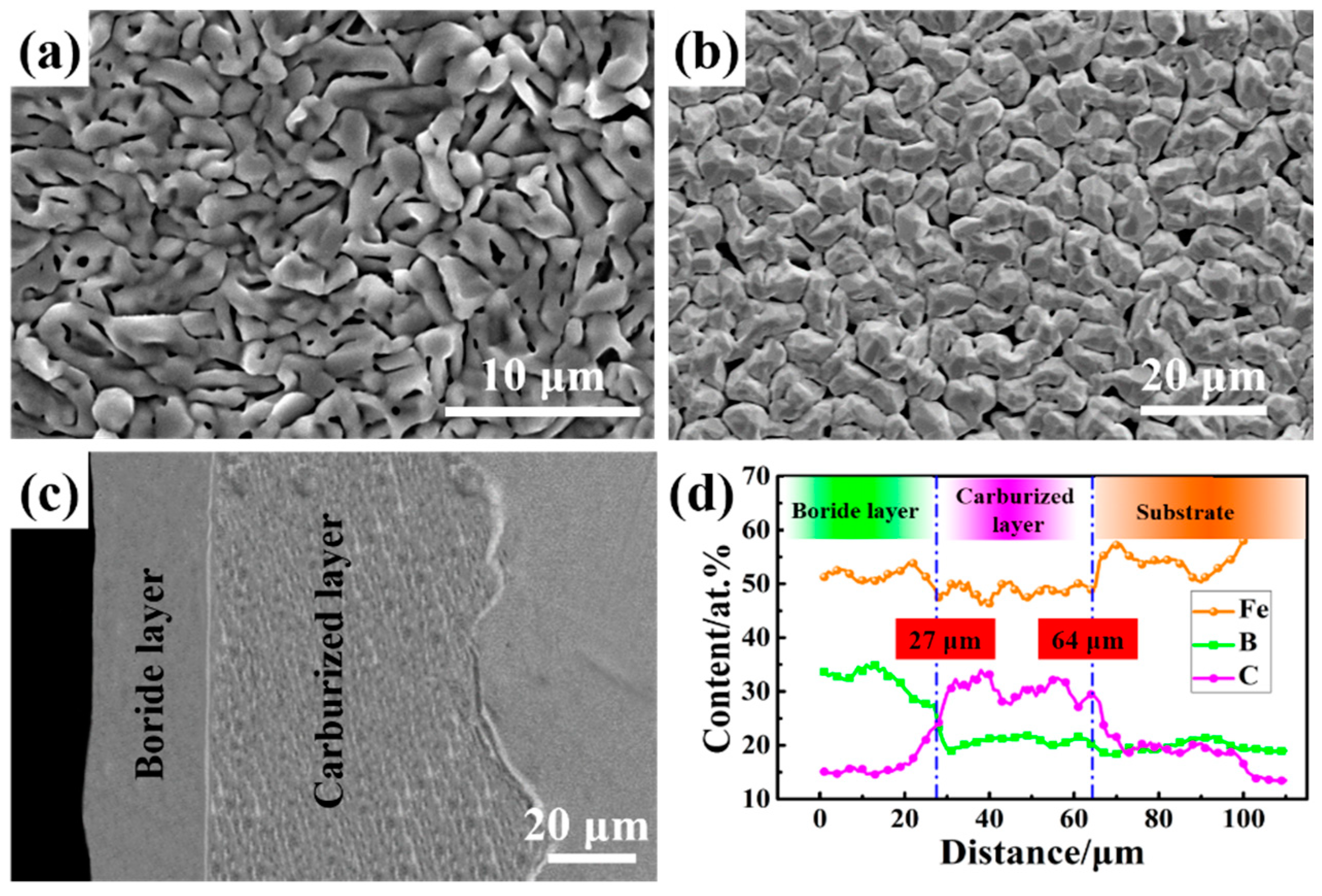
The microtopography of sample is shown in
Figure 2. As observed in
Figure 2a, the carburized sample exhibits a homogeneous and needle-like microstructure without cracks. In
Figure 2b, the boronized layer after carburizing consists of submicron-sized particles and the average roughness of the layer was 1.189 μm. The cross-section microstructure of the borocarburized layer is uniform and even, which is different from the single boronized layer [
30]. The boride layer and the carburized layer can be obviously observed along with the depth of the borocarburized layer. Moreover, the penetration of boron and carbon atoms can also reduce the brittleness of the boride layer [
3]. As shown in
Figure 2d, the EDS result of the cross-section from surface of the coating to along the depth direction of the substrate indicates that the thickness of the boride layer and carburized layer is 27 μm and 64 μm, respectively. It can be found that boron and carbon show a gradient change in the coating, showing complete metallurgical diffusion behavior, which helps to improve the adhesion between the coating and the substrate. In the boronized layer, the concentration of carbon atoms is very low, which is in line with the viewpoint that the solubility of carbon atoms in the boronized layer is very low [
31].
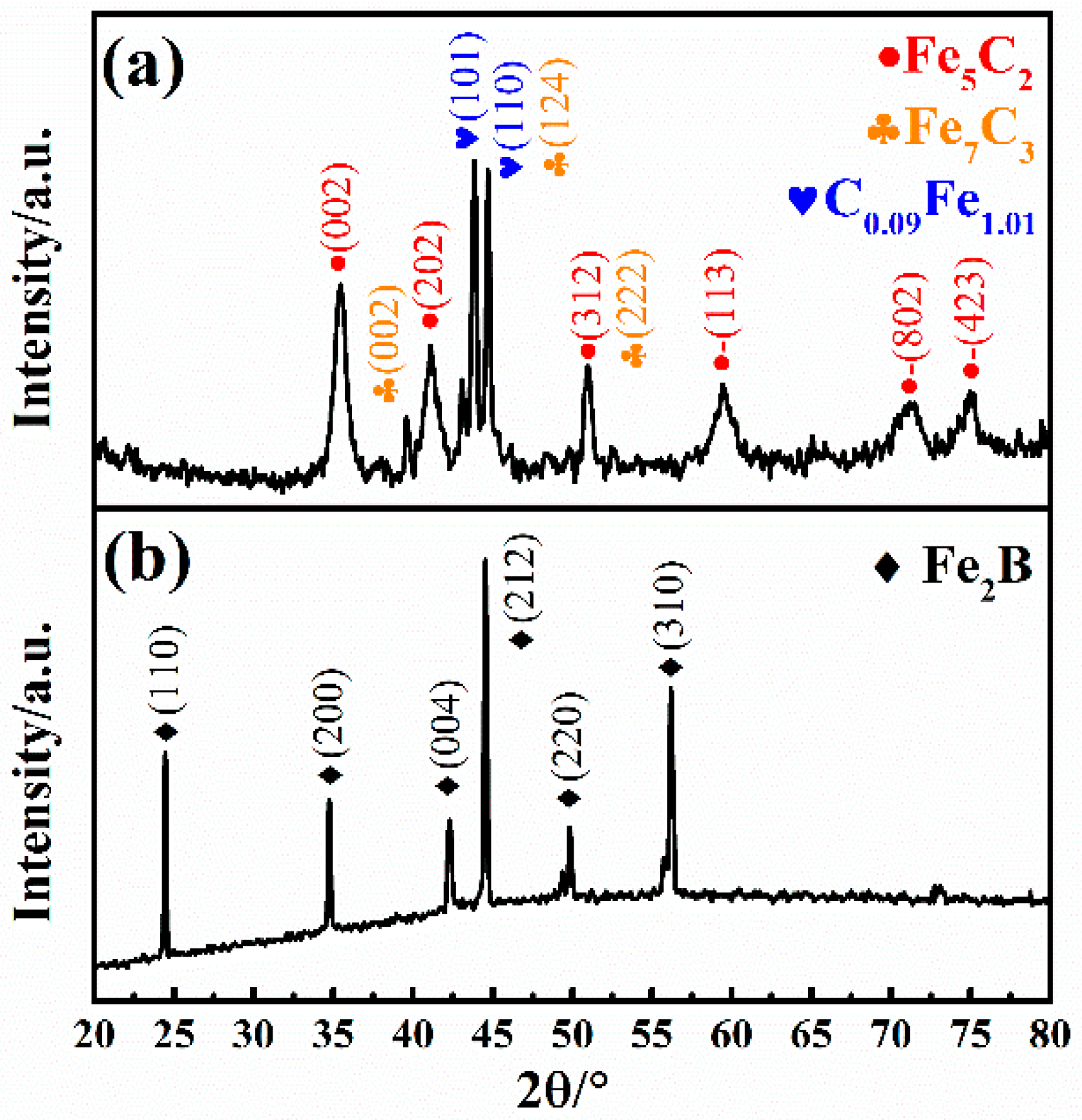
As we can see from the XRD results in
Figure 3a, apart from the detected orthorhombic Fe
7C
3 phase (PDF75-1499) and tetragonal C
0.09Fe
1.91 phase (PDF44-1292), the carburized sample exhibits a main phase of monoclinic Fe
5C
2 phase (PDF89-7272). Furthermore, an individual phase of tetragonal Fe
2B (PDF89-1993) phase with desirable purity is observed in
Figure 3b after introducing the borocarburized layer. Interestingly, an orthorhombic FeB (PDF76-0092) phase for the traditional boronizing layer [
32] is not detected in the XRD results. In the process of boronizing, due to the continuous bombardment of various particles, the substrate surface becomes clean and a large numbers of defects are formed on it, which can accelerate the diffusion rate of boron atom and hinder the formation of boron-rich FeB. At the same time, at the temperature of layer preparation (working temperature 1050~1100 °C), the FeB phase can be transformed into Fe
2B phase [
13]. The disappearance of the FeB phase can effectively reduce the residual stress caused by the large difference in thermal expansion coefficient between the Fe
2B phase and FeB phase, thereby reducing the spalling possibility of the boride layer during the cooling process. This is also the difference between the double glow plasma device and some other traditional pieces of equipment. The single Fe
2B phase layer can be obtained via the double glow plasma device without any other heat treatment process [
9,
13,
14].
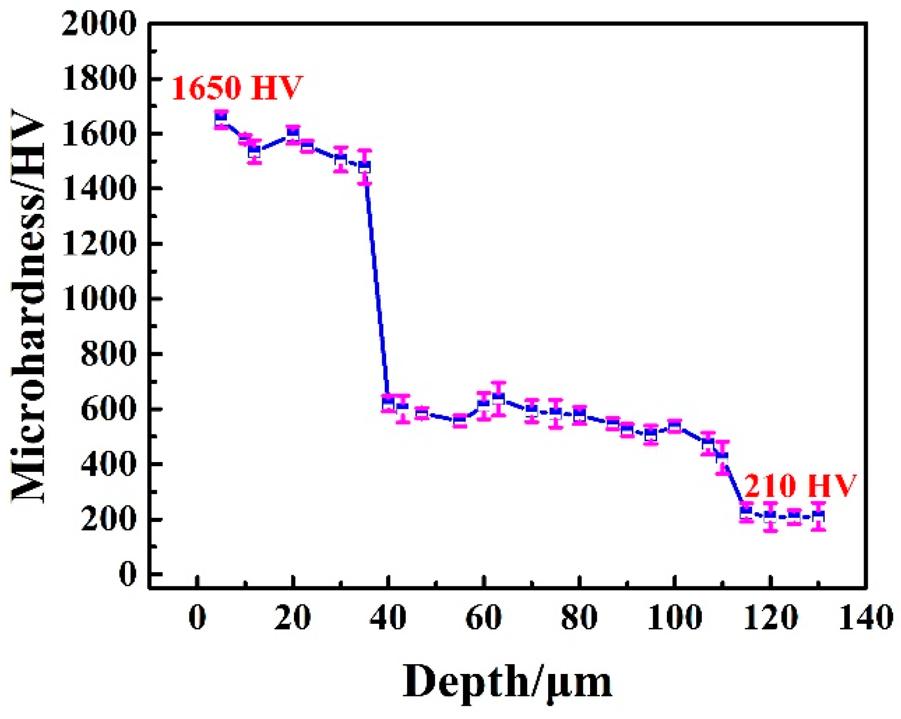
Figure 4 depicts the microhardness distribution of the borocarburized layer. As observed in this figure, the maximum hardness of 1650 Vickers hardness (HV) is obtained for the top boride layer. However, the hardness of the original steel substrate is only 210 HV, indicating an obvious enhancement in hardness after introducing the borocarburized layer. Additionally, the hardness of the transition carburized layer is around 600 HV. Therefore, the introduction of the carburized layer reduces the hardness gradient of the single boride layer and improves the comprehensive mechanical properties of the coating [
33]. Meanwhile, the surface hardness of the borocarburized layer is much higher than that of the carburized layer, which is beneficial to wear resistance. In fact, the surface microhardness and brittleness of the Fe
2B phase layer are lower than those of FeB phase. Due to the extremely high internal stress during cooling, there are many risks of cracks and spalling in the surface area of FeB/Fe
2B layers [
3,
9].
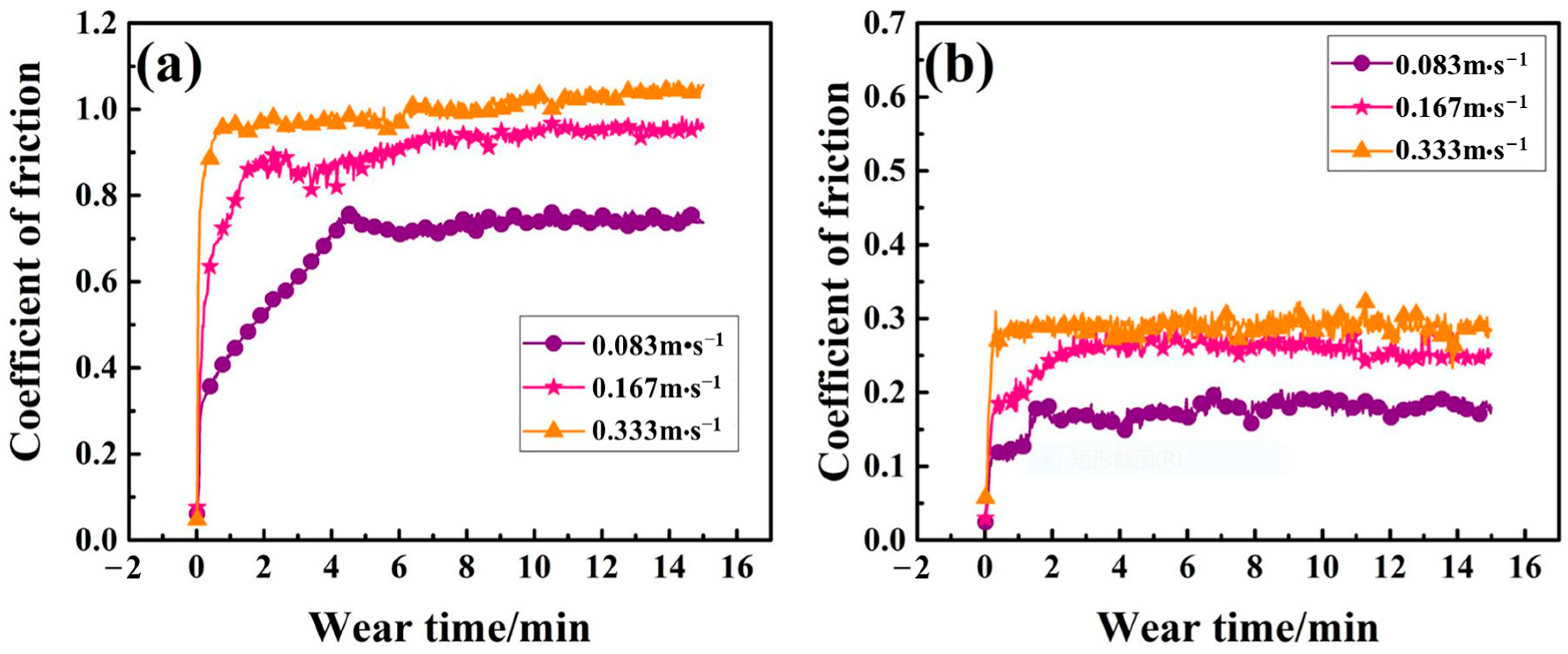
The friction coefficients of samples with and without layers under dry-sliding against ZrO
2 ball with 0.083 m·s
−1, 0.167 m·s
−1 and 0.333 m·s
−1 speed at room temperature are shown in
Figure 5. As for the Q235 substrate, a rapid increase in friction coefficient is observed at the initial stage. With the gradual increase in wear time, the friction coefficient tends to be stable at the range of 0.7 to 1. The large fluctuations in the friction coefficient of the substrate are due to the greater plasticity, which is prone to adhesive wear. Additionally, at the initial friction stage, the wear debris embedded in the substrate is also prone to generate relatively large friction. For further increased wear time, the wear debris is easily broken, and the friction force is reduced. It can be seen from the figure that the friction coefficient of the substrate increases with the increase in the rotation speed. This is because the increased rotation speed can bring an increase in the temperature of the contact surface and accelerates the oxidation, while the iron oxide is not dense and is unable to protect the substrate. Instead, it increases the hardness of the wear debris and the friction coefficient. As for the borocarburized layer, the friction coefficient is much lower than that of the Q235 substrate, which is basically stable between 0.15 and 0.28. The above difference in relatively stable friction coefficients can be attributed to the difference in specimen hardness (see
Figure 4), which has been verified by previous researchers [
34]. The friction coefficient of the borocarburized layer also increases with the increase in rotating speed. However, for conventional FeB or FeB/Fe
2B layers, there is a risk of peeling off the surface, which may lead to friction fluctuations of the friction coefficient [
3,
9]. This shows that a single-phase Fe
2B may provide better anti-friction performance.
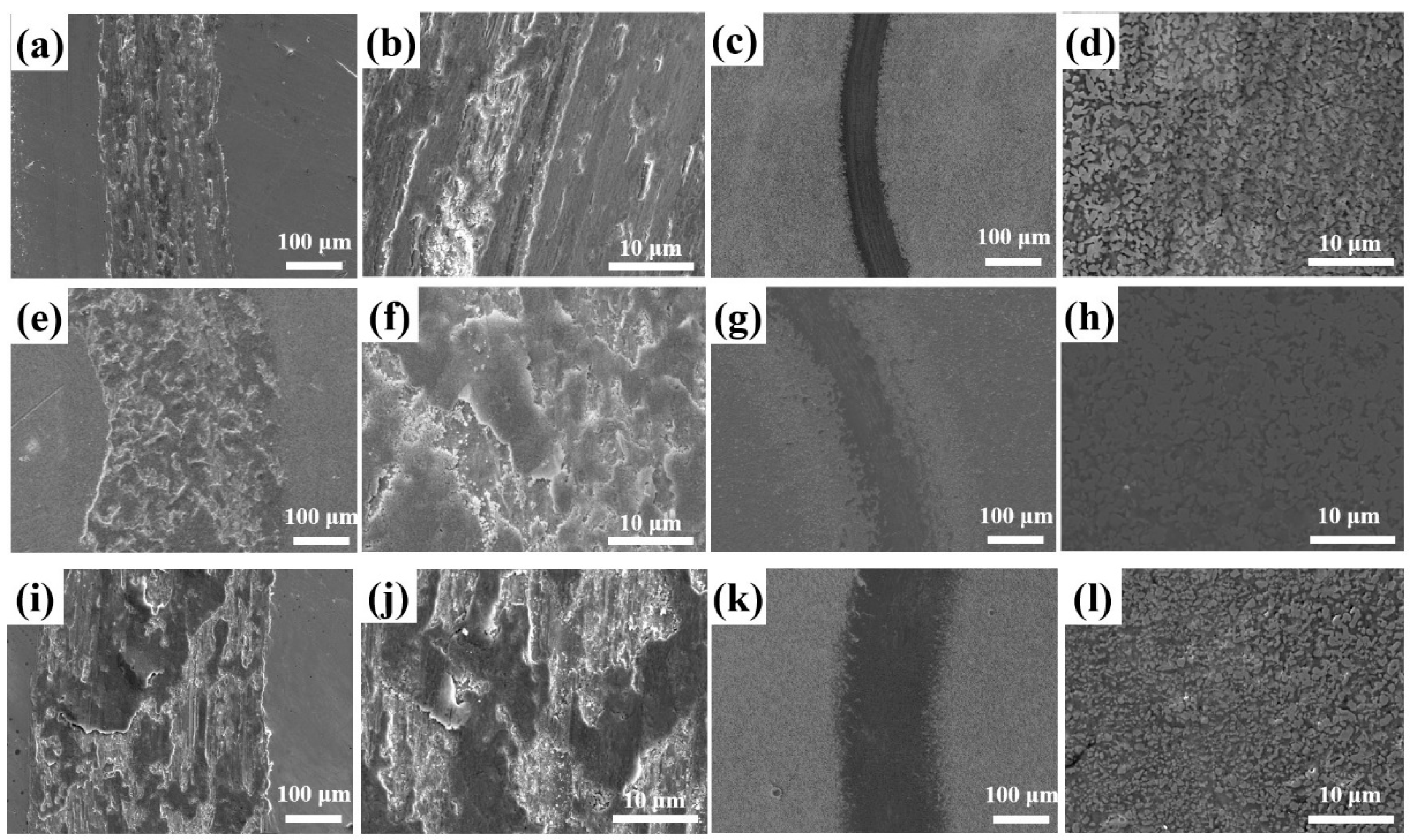
The wear morphology of Q235 low-carbon steel and the borocarburized layer at different speeds is shown in
Figure 6. As observed in
Figure 6a, obvious tears and scratches are distributed in the wear area of the substrate when the speed is 0.083 m·s
−1. It can be found from the amplified
Figure 6b that there are many furrows on the wear track surface, containing partly tearing and sticking areas. As shown in
Figure 6c, the wear track of substrate after introducing a borocarburized layer is slightly scratched and presents a narrower scar width, which shows a desirable wear resistance. Uniform wear morphology of the borocarburized layer can be obviously observed from the amplified
Figure 6d, showing a smooth characteristic of the entire wear track area. The wear track morphology of the substrate at low speed indicates that the wear mechanism is mainly abrasive wear, accompanied by slight adhesive wear, while the slight wear track morphology is observed at low speed on the surface of the borocarburized layer, showing the characteristics of abrasive wear. The above phenomenon can be well explained by the high hardness of the boronized layer.
With the increased speed of 0.167 m·s
−1, the wear track morphology of Q235 low-carbon steel substrate and borocarburized layer can be seen in
Figure 6e–h. As shown in
Figure 6e, the wear track width significantly increases with the increased speed. The enlarged morphology in
Figure 6f reveals an obvious tearing and warping on the surface of the wear track, and a large area of sticking phenomenon occurs. After introducing a borocarburized layer, only a little plastic deformation in the wear track area is observed in
Figure 6g, and the wear track width slightly increases compared to that at low speed. In summary, when the speed is increased to 0.167 m·s
−1, the substrate is dominated by adhesive wear, accompanied by fatigue wear and abrasive wear. However, the coating undergoes a slight plastic deformation, and the wear mechanism shows a characteristic of fatigue wear, which can be explained as follows. During the wear process, friction wear of the ZrO
2 ball and sample surface will increase with the increase in speed, bringing increased heat generated by friction and sharply rising temperature in the local area of the wear track surface. However, the borocarburized layer contains a boronized layer with high hardness, which can effectively reduce the actual contact area of the friction pair and the sample surface, thereby improving the wear resistance.
With the further increased speed of 0.333 m·s
−1, as shown in
Figure 6i, the wear track width of the substrate is further increased and a large area of wear scar is warped and peeled, leaving many furrows with different depths. As shown in the enlarged morphology in
Figure 6j, an amount of abrasive debris is randomly scattered on the wear track surface. Additionally, the spalling phenomenon occurs in some areas.
Figure 6k shows the wear track morphology after introducing the borocarburized layer at 0.333 m·s
−1 speed. It can be found that the wear track width is slightly wider than that at low speed and the wear track surface is relatively complete. The enlarged morphology depicted in
Figure 6l shows that only plastic deformation occurs on the wear track surface, where a few micro cracks remain, and no damage occurs. In summary, for the speed of 0.333 m·s
−1, the wear mechanism of the substrate becomes a coexisting wear mechanism of cohesive wear, abrasive wear, and oxidative wear. As for the borocarburized layer, the wear track morphology exhibits negligible micro cracks, indicating an excellent wear resistance of the borocarburized layer under high speed conditions.
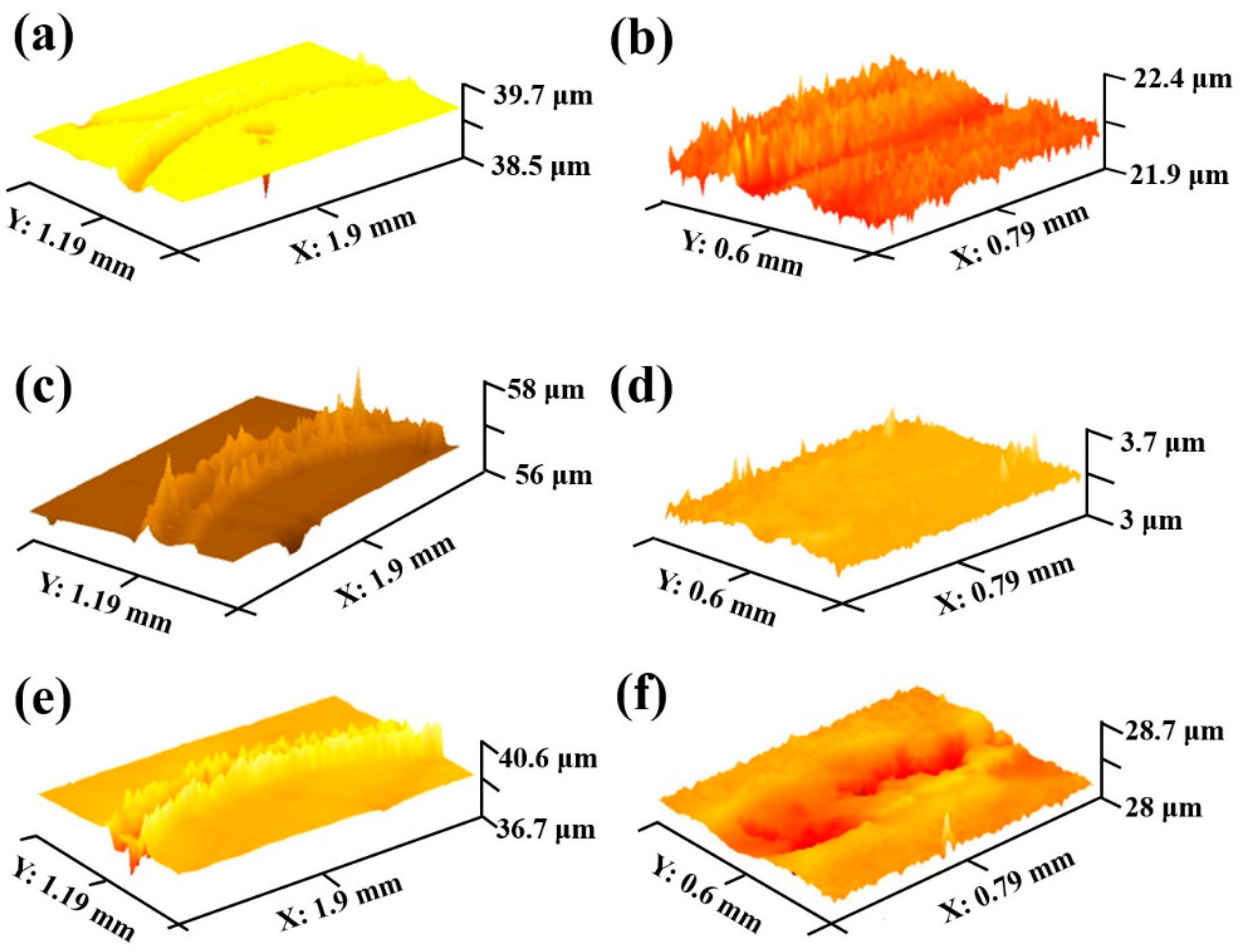
Figure 7 is the three-dimensional morphology of Q235 low-carbon steel substrate and the borocarburized layer at different speeds. It can be seen from the figure that the wear track width of the substrate increases significantly with the increase in speed. Additionally, the accumulated height of the wear track edge also increases as well, which can be explained by the increased degree of wear with the increased speed, leading to severe friction and plastic deformation on the sample surface. As for the borocarburized layer, the increased speed will also bring an increase in width and depth of wear track; however, the degree of increase is much smaller than that of the substrate. The above results correspond well with previous wear morphology.
Sliding wear results of the substrate and borocarburized layer at different speeds are shown in
Table 1. In order to measure the friction and wear properties, the wear volume and wear rate can be calculated as follows [
35,
36]:
with V being the wear volume (mm
3); r the rotating radius (mm); b the width of wear track (mm); h the depth of wear track (mm); K the specific wear rate (10
−7·mm
3·N
−1·m
−1); P the load (N); S the sliding distance (m). As high speed can bring an increase in frictional heat and the degree of wear of the sample, consequently, the wear volume increases significantly at high speed. The specific wear rate of the substrate at the speed of 0.083 m·s
−1, 0.167 m·s
−1 and 0.333 m·s
−1 is 11.47 × 10
−7 mm
3·N
−1·m
−1, 33.71 × 10
−7 mm
3·N
−1·m
−1 and 83.18 × 10
−7 mm
3·N
−1·m
−1. For the borocarburized layer, the specific wear rate is reduced by 92.24%, 93.53% and 96.51%, respectively. The improved wear resistance can be attributed to the introduced borocarburized layer, which fundamentally enhanced the hardness of the coating.
Electrochemical characteristics of the substrate and borocarburized layer were carried out via potentiodynamic polarization measurement to determine the corrosion mechanism. The potentiodynamic polarization curve is depicted in
Figure 8. The cathodic reaction in the polarization curve corresponds to hydrogen evolution, while the anodic reaction curve represents the corrosion reaction of the boronized layer. The anodic polarization slope is higher than that of the cathodic polarization, which indicates that the whole corrosion reaction is mainly controlled by the anodic reaction. In addition, electrochemical parameters evaluated from potentiodynamic polarization curves such as corrosion current density I
corr (A/cm
2), corrosion potential E
corr (V vs. SCE) and polarization resistance R
p are listed in the inset table in
Figure 8. As observed in
Figure 8, corrosion potential E
corr moves towards the positive direction after introducing the borocarburized layer. The corrosion current density I
corr decreases from 2.025 × 10
−6 A/cm
2 (substrate) to 1.480 × 10
−6 A/cm
2 (borocarburized layer). Additionally, polarization resistance R
p increases from 10,894 Ω·cm
−2 of substrate to 18,150 Ω·cm
−2 of borocarburized layer. The above results indicate that the borocarburized layer can improve corrosion resistance of low-carbon steel to some extent.
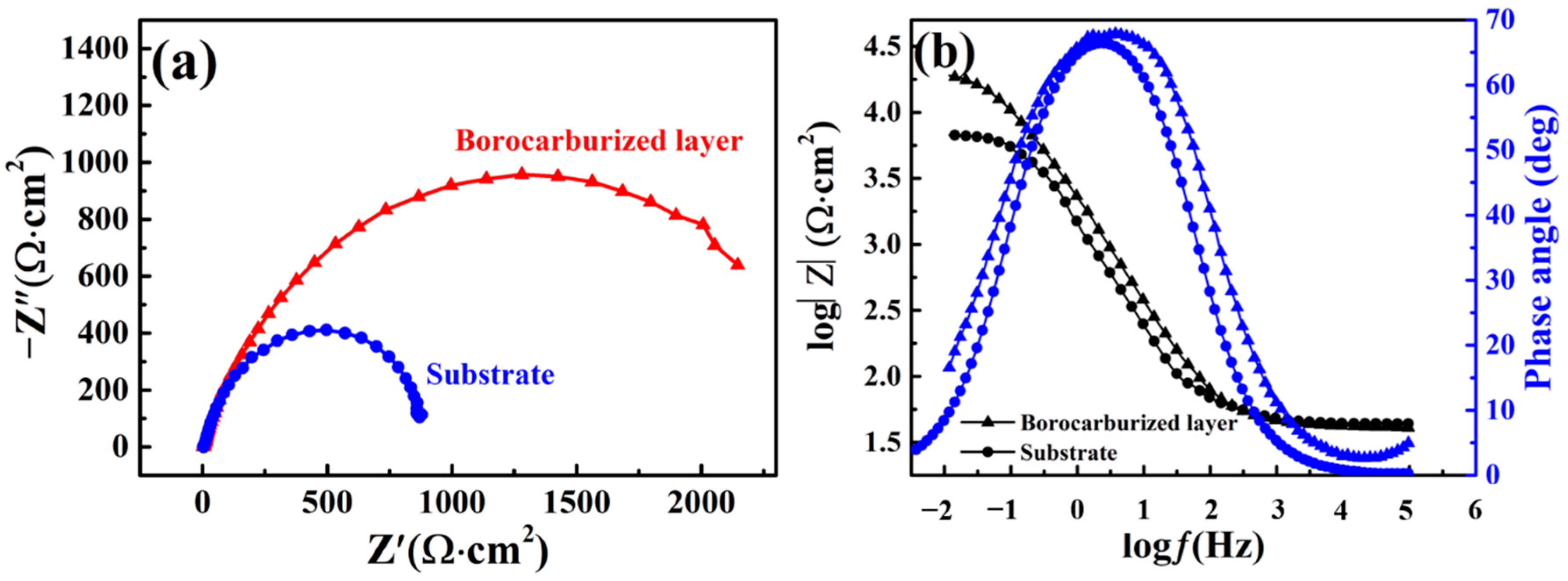
In order to determine the corrosion behavior of the interface between solution and metal, an impedance measurement was carried out. Nyquist plots and Bode plots of borocarburized layer and substrate are presented in
Figure 9. The observed typical capacitive loop of the Nyquist plot indicates that the reaction is controlled by charge transfer [
37]. Therefore, the diameter of the capacitive loops in the Nyquist plots and the impedance value of the Bode plots both have a close connection with corrosion resistance. As obviously shown in
Figure 9a, the diameter of the capacitive loop of the borocarburized layer is larger than that of the substrate, indicating an enhancement in corrosion resistance after introducing the borocarburized layer. Previous studies [
38,
39] have proven that the formation of boride was advantageous to improve the corrosion resistance of steels, which is in accordance with our results. As observed in
Figure 9b, the impedance value of the borocarburized layer is larger than that of substrate, which also indicates a better corrosion resistance. It can be seen from
Figure 9b that there is only one time constant in the corrosion process of both the substrate and the layer. This phenomenon may be due to the small impedance value of the corrosion products, which cannot be reflected in the Bode diagram.
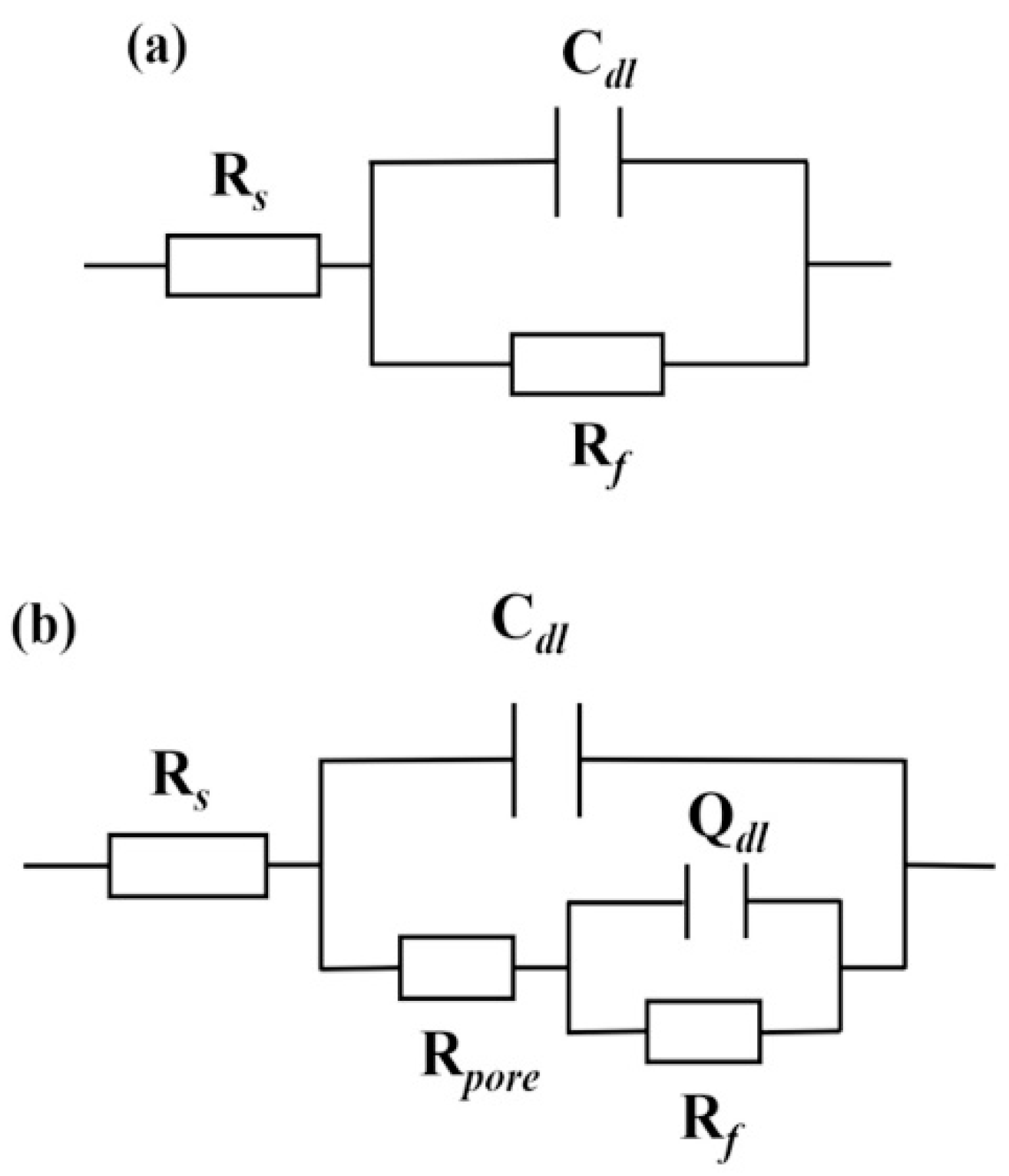
The equivalent circuit is proposed in
Figure 10 to further analyze the electrochemical process of the electrode/electrolyte surface, where R
s is the solution resistance from reference electrode to sample, C
dl is the double layer capacitors in the reaction interface, R
f is the charge transfer resistance of the reaction interface. As for the layer, it possesses a double-layer structure, Q
d1 represents the constant phase angle element associated with the boronized layer, and R
pore represents the porous resistance of the boronized layer.
During the corrosion test, R
f is proportional to corrosion resistance. According to
Table 2, the R
f of the borocarburized layer is larger than that of the substrate. The above results indicate that the corrosion resistance of low-carbon steel is improved after introducing the borocarburized layer. Moreover, the protective film of boride can resist the transport of aggressive Cl
−, thereby protecting inner metal from the aggressive environment. Returning to the electrochemical measurements (
Figure 8), the increased R
p and the decreased I
corr revealed that the corrosion rate of the coating declines after the formatting of the borocarburized layer on Q235 low-carbon steel, which can also explain the improved corrosion resistance to some extent. The corrosion resistance of the boronized layer is related to micro cracks, so the corrosion resistance performance of the borocarburized layer is largely due to the uniform Fe
2B layer without cracks. Meanwhile, for the conventional FeB/Fe
2B layers, stress concentration tends to occur at the FeB/Fe
2B phase boundary due to the different expansion coefficients between the two phases. Thus, micro cracks in these FeB/Fe
2B layers are feasible during the preparation and service [
39,
40].


