Article

Porous CaP Coatings Formed by Combination of Plasma Electrolytic Oxidation and RF-Magnetron Sputtering

by
Anna Kozelskaya
1,*,
Gleb Dubinenko
1,
Alexandr Vorobyev
1,
Alexander Fedotkin
1,
Natalia Korotchenko
2,
Alexander Gigilev
2,
Evgeniy Shesterikov
3,4,
Yuriy Zhukov
5 and
Sergei Tverdokhlebov
1,*
1
School of Nuclear Science & Engineering, Tomsk Polytechnic University, 634050 Tomsk, Russia
2
Department of Inorganic Chemistry, Tomsk State University, 634050 Tomsk, Russia
3
Laboratory of Radiophotonics, V.E. Zuev Institute of Atmospheric Optics SB RAS, 634055 Tomsk, Russia
4
Nanotechnology Center, Tomsk State University of Control Systems and Radioelectronics, 634050 Tomsk, Russia
5
Department of Nuclear-Physics Research Methods, Saint-Petersburg State University, 199034 Saint-Petersburg, Russia
*
Authors to whom correspondence should be addressed.
Coatings 2020, 10(11), 1113; https://doi.org/10.3390/coatings10111113
Submission received: 28 October 2020 / Revised: 16 November 2020 / Accepted: 17 November 2020 / Published: 19 November 2020
(This article belongs to the Special Issue Plasma Electrolytic Oxidation (PEO) Coatings)

Abstract

:
The porous CaP subcoating was formed on the Ti6Al4V titanium alloy substrate by plasma electrolytic oxidation (PEO). Then, upper coatings were formed by radio frequency magnetron sputtering (RFMS) over the PEO subcoating by the sputtering of various CaP powder targets: β-tricalcium phosphate (β-TCP), hydroxyapatite (HA), Mg-substituted β-tricalcium phosphate (Mg-β-TCP) and Mg-substituted hydroxyapatite (Mg-HA), Sr-substituted β-tricalcium phosphate (Sr-β-TCP) and Sr-substituted hydroxyapatite (Sr-HA). The coating surface morphology was studied by scanning electron and atomic force microscopy. The chemical composition was determined by X-ray photoelectron spectroscopy. The phase composition of the coatings was studied by X-ray diffraction analysis. The Young’s modulus of the coatings was studied by nanoindentation test. RF-magnetron sputtering treatment of PEO subcoating resulted in multileveled roughness, increased Ca/P ratio and Young’s modulus and enrichment with Sr and Mg. Sputtering of the upper layer also helped to adjust the coating crystallinity.

Graphical Abstract

1. Introduction

Implant integration on the bone site, together with the bone fracture consolidation time and effectiveness, are among the most significant conditions for effective bone healing. Bioactive calcium phosphate (CaP) coatings are assigned to improve metallic implant osseointegration and reduce bone healing time. Micro-arc oxidation (MAO) or plasma electrolytic oxidation (PEO) and radio frequency magnetron sputtering deposition (RFMS) are the most developed CaP coating deposition methods.
Compared to other surface modification methods, PEO is economically efficient and best for the deposition of bioactive coatings with open porosity [1,2]. PEO coatings are excellent for their high wear and corrosive resistance [3,4,5,6], and low residual stress on the surface due to porous morphology [7]. Porous morphology of the coating enhances implant osseointegration and promotes bone tissue regeneration. Moreover, the raw surface provides a higher available surface area for cell seeding and bone morphogenetic protein (BMP) adsorption [8]. Another PEO feature is the feasibility of modifying the surface of complex shape and 3D-printed implantable devices. In turn, RF-sputtered coatings are dense and known for their higher calcium-to-phosphorus (Ca/P) ratio. RFMS allows for coating deposition on the various types of materials, including ceramics and polymers. This method is variable not only due to substrate material options, but also due to the material of the sputtered target.
RFMS and PEO are also known for their disadvantages. PEO coatings can only be deposited on the surface of the valve metals [9,10,11,12]. RFMS requires expensive vacuum equipment and restricted by a low rate of deposition, which determines the low efficiency of this method [13,14]. Moreover, magnetron sputtering cannot ensure coating deposition on the inner surfaces of complex-shaped substrates. A combination of PEO and RFMS could consolidate their advantages and compensate for the drawbacks.
A combination of PEO and RFMS was used previously [15,16]. Park et al., revealed the effect of enhanced corrosion potential and passive current density after RFMS of Mn on the Ti–29Nb–xHf substrate [15]. The molar ratio of (Ca + Mn)/P was growing with the increase in Mn sputtering time. Hwang et al. combined PEO and RFMS to fabricate CaP/Zn coatings on the Ti–6Al–4V [16]. Coatings RFMS with Zn showed a higher cell proliferation rate. Extended Zn RFMS leads to an increased (Ca + Zn)/P ratio, growth of the amorphous phase and increase in Zn corrosion rate.
In the presented study, we sputtered thin RFMS CaP coatings of various compositions to enhance the osteostimulating properties and increase the Ca/P ratio of the PEO CaP subcoating. An increase in Ca/P ratio, the formation of multileveled roughness and enrichment with Mg and Sr are engaged to potentially regulate osteoblasts’ and osteoclasts’ functionality and enhance cell attachment and proliferation [17,18,19,20].

2. Materials and Methods

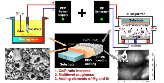
2.1. Coatings Formation

Ti–6Al–4V 10 mm in diameter and 1-mm-thick disks were used as substrates for coatings formation. Preparation of the surface of the samples before coating included cleaning in an ultrasonic bath in distilled water and chemical etching in an aqueous solution of nitric and hydrofluoric acids taken in volume ratios of HNO3:HF:H2O = 1:2.5:2.5, at the temperature of 15–20 °C for 10–15 s, followed by neutralization in a 1% aqueous solution of sodium hydroxide and repeated washing with distilled water.
PEO subcoating was formed on the “Micro-arc oxidation complex” (PEOC) designed in the Laboratory for Plasma Hybrid Systems, The Weinberg Research Center, School of Nuclear Science & Engineering of Tomsk Polytechnic University (Tomsk, Russia). A supersaturated solution of CaO in 10% H3PO4 with 10 g/L dispersed hydroxyapatite (particle size up to 70 μm) was used as an electrolyte. The density and pH of electrolyte were 1080–1090 kg/m3 and 2.03, correspondingly. PEO subcoating was formed at the following operating mode: voltage—320 V, voltage rise rate—3 V/s, pulse repetition rate—200 Hz, pulse duration 100 μs, coating formation time—15 min. The temperature of electrolyte was keeping about 15 °C by cooling the bath by water flow. Coated samples were washed in distilled water and dried at 120 °C on air for 30 min.
Various RF magnetron sputtered upper coatings were formed by the sputtering of six different powder targets: pure β-tricalcium phosphate (β-TCP), pure hydroxyapatite (HA), Mg-substituted β-tricalcium phosphate and Mg-substituted hydroxyapatite (Mg-β-TCP, Mg-HA, Mg substitutions concentration was 1.53 wt.% ± 0.01 wt.%), Sr-substituted β-tricalcium phosphate and Sr-substituted hydroxyapatite (Sr-β-TCP, Sr-HA, Sr substitutions concentration was 3.39 wt.% ± 0.09 wt.%). β-TCP, Mg-β-TCP, Sr-β-TCP powders were synthesized in Riga Technical University (Riga, Latvia) [13]. HA-based powders were synthesized by microwave assisted method in Tomsk State University (Tomsk, Russia) [14]. Liquid phase synthesis of MgHA and SrHA powders was carried out using a stoichiometric ratio Ca/P = 1.67 ((Ca + Me)/P = 1.67) and the following reactions:
(10–x)Ca(NO3)2 + 6(NH4)2HPO4 + xMg(NO3)2 + 8NH4OH = Ca(10–x)Mgx(PO4)6(OH)2 + 6H2O + 20NH4NO3
(10–x)Ca(NO3)2 + 6(NH4)2HPO4 + xSr(NO3)2 + 8NH4OH = Ca(10–x)Srx(PO4)6(OH)2 + 6H2O + 20NH4NO3
where x = 0.1; 0.3; 0.5 (mol), Me—metal.
An aqueous solution of calcium nitrate was mixed with a solution of ammonium hydrophosphate in concentration 0.5 and 0.3 M, respectively. The weighed sample of magnesium or strontium nitrate was added to the calcium nitrate solution. A reactant solution pH value of 10–11 was reached with an aqueous solution of ammonia (25%, ρ = 0.9 g/mL). The mixture underwent microwave exposure with 110 W for 40 min and then was carried at room temperature for 48 h. The precipitate was filtered, rinsed with a diluted solution of ethanol and dried until constant weight (~15 h) at 95 °C. Dried powders were annealed for 4 h at 900 °C.
Targets were formed by spreading powders in the hexagonal crucible with an area of 230 cm2 and a depth of 0.6 cm. The volume was constant for all powders and equal to approximately 138 cm3. The preliminary pressure in the chamber was 10−3 Pa, and the working pressure (Ar) was 0.5 Pa. The distance between the sputtering target and the substrate was 40 mm, power density—4.8 W/cm2, sputtering time—7 h for HA-based powders and 21 h for β-TCP-based powders.

2.2. Coating Thickness

PEO sub-coating thickness was studied by the eddy current testing with the use of Konstanta 5 (KONSTANTA, Saint-Petersburg, Russia) equipment. RFMS upper coating was studied on the silicon witness samples with the use of Ellips 1891 SAG (NPK “Nanotechnology Center”, Novosibirsk, Russia) spectral ellipsometer.

2.3. Scanning Electron Microscopy (SEM)

Coating morphology was studied on the scanning electron microscope JCM-6000 (JEOL, Tokyo, Japan) using a backscattered electron detector in a low vacuum mode. Micrographs were obtained at 15 kV accelerating voltage and 3.5 μA beam current. For better micrograph quality, all samples were preliminarily sputter-coated with gold using the SC7640 magnetron sputtering system (Quorum Technologies Ltd., Newhaven, UK).

2.4. Atomic Force Microscopy (AFM)

The surface morphologies of the coatings were examined using atomic force microscope (Solver-HV, NT-MDT, Moscow, Russia) operating in contact mode.

2.5. X-ray Photoelectron Spectroscopy (XPS)

The chemical composition of the coatings was studied using an Escalab 250Xi instrument (Thermo Fisher Scientific Inc., Saint-Petersburg, Russia) equipped with monochromatic AlKα radiation (photon energy 1486.6 eV). Total energy resolution was about 0.55 eV. Spectra were recorded in the constant pass energy mode at 100 eV for survey spectrum and 50 eV for element core level spectrum, using an XPS spot size of 650 μm. Investigations were carried out at room temperature in ultrahigh vacuum of 1 × 10⁻⁹ mbar (in case of the use of electron-ion compensation system, Ar partial pressure was 1 × 10⁻⁷ mbar). The library of the reference XPS spectra including the atomic registration sensitivity factors was provided by the instrument manufacturer within the Avantage Data System (Thermo Fisher Scientific Inc.). Peaks were deconvoluted using the Avantage software (version 5.977) which was set to a Shirley background subtraction followed by peak fitting to Voigt functions having 80% Gaussian and 20% Lorentzian character.

2.6. X-ray Diffraction (XRD) Analysis

Coating phase composition was studied with the use of Shimadzu XRD 6000 (Shimadzu, Tokyo, Japan) X-ray diffractometer using CuKα radiation. Diffraction patterns were obtained in Bragg–Brentano geometry with 40 kV accelerating voltage, 30 mA beam current, in the range of 10°–80° scanning angles with 1°/min scanning speed, 0.02° scanning step and 1 s signal acquisition time.

2.7. Nanoindentation

Composite coating Young’s modulus was measured with the use of Nanoindenter G200 (Agilent’s Electronic Measurement, Santa Clara, CA, USA). Indentation was performed with triangular Berkovich pyramid at 50 mN at least five times on each sample. Young’s modulus was defined according to the ISO14577 [21].

3. Results

Two consecutive layers formed composition CaP coatings: thick PEO subcoating and thin RFMS upper coating of six different compositions. The thickness of each layer and total composite coating thickness are presented in Table 1. We observed no significant difference in the thickness of PEO subcoating on all samples, which was approximately 35 μm. However, the thickness of RFMS upper coating depends on the target composition and ion substitutions. β-TCP-based targets have a lower rate of sputtering comparing with HA-based targets. Another key factor affects the rate of sputtering is Mg and Sr ion substitutions. Sr substitution increases the rate of β-TCP RFMS, while Mg has no significant effect on the sputtering rate. We discussed the effect of Sr and Mg substitutions on the β-TCP RFMS rate in more detail in our previous study [22]. For HA-based upper coatings, we observed no significant effect of Sr and Mg substitution on the rate of sputtering. We revealed significant thickness differences with PEO only for the PEO + HA composite coating.

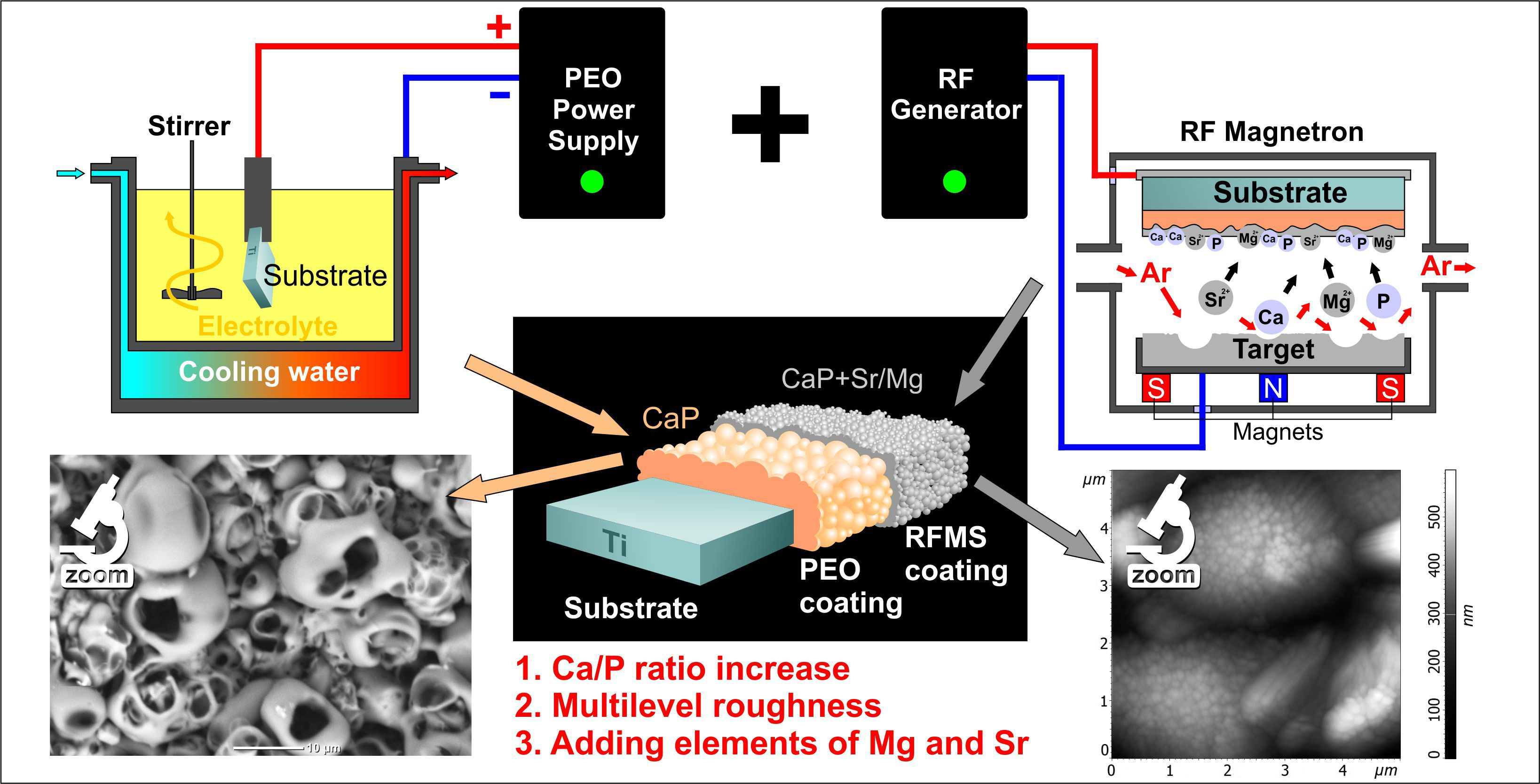
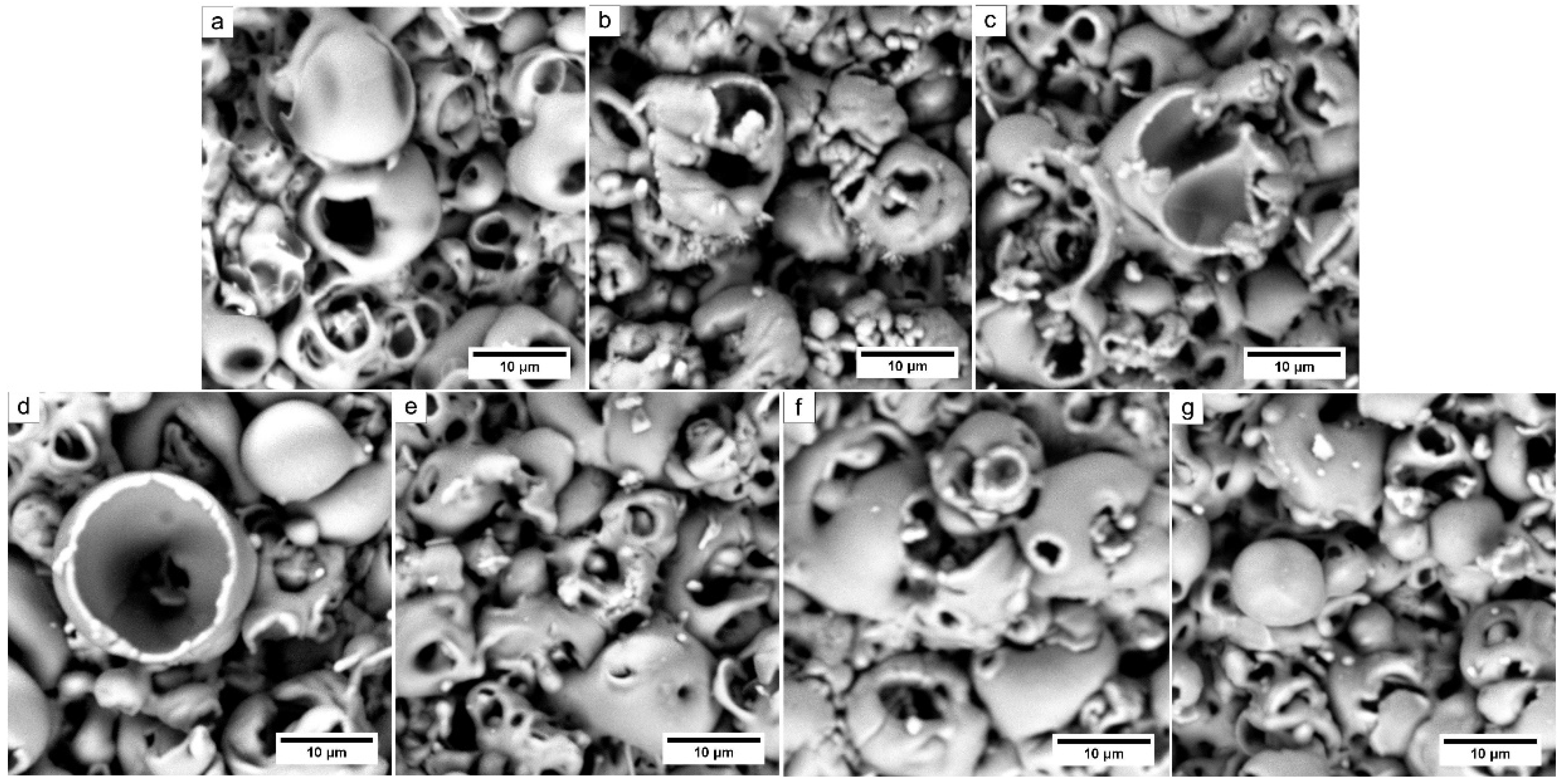
3.1. Composite Coating Morphology

Close-standing highly porous groups of spheroidal structures (spherulites) form the surface of PEO subcoating (Figure 1a). The average spherulites lateral dimension varies from 5 to 20 μm and open spherulites walls thickness from 1 to 1.5 μm. We suppose that high-temperature microplasma discharges during PEO initiate erosion and partial destruction of spherulites, which results in the formation of a sponge-like structure. On the macroscale, this sponge structure is stable after RFMS of the upper coating. Thin upper coating replicates the subcoating macrorelief. However, at high magnification, we observe crystallite-like structures on the spherulites’ surfaces (Figure 1b–g). We observed a similar surface morphology for composition coatings with β-TCP-based RFMS upper coatings (Figure 1e–g). It should be noted that distinct dendritic crystallites cover the surface of spherulites with HA upper coating (Figure 1b). We associate this crystallization effect with an intense surface heating due to bombarding substrate by high-energy plasma particles during RFMS of the HA target.
An AFM study of thin RFMS surface layer showed the relationship between surface structure and composition of the sputtered target. We observed RFMS crystallites over the PEO spherulites surface in the images of composite coatings (Figure 2b–g). Homogeneously distributed crystallites are clearly visible in the images of PEO + HA (Figure 2(b2)) and PEO + Mg-HA (Figure 2(d2)). HA crystallites are oval and have a 0.31 ± 0.06 μm2 approximate area (Figure 2(b3)). Mg-HA crystallites are smaller and near the quasi-equilibrium shape with an approximate area of 0.06 ± 0.02 μm2 (Figure 2(d3)). However, most of the composite coatings, including PEO + Sr-HA (Figure 2(c1–c3)), PEO + β-TCP (Figure 2(e1–e3)), PEO + Sr-β-TCP (Figure 2(f1–f3)), and PEO + Mg-β-TCP (Figure 2(g1–g3)), are formed by HA-type crystallites. Presumably, Figure 2(c3,f3) shows initial PEO spherulites with no traces of RFMS crystallites.

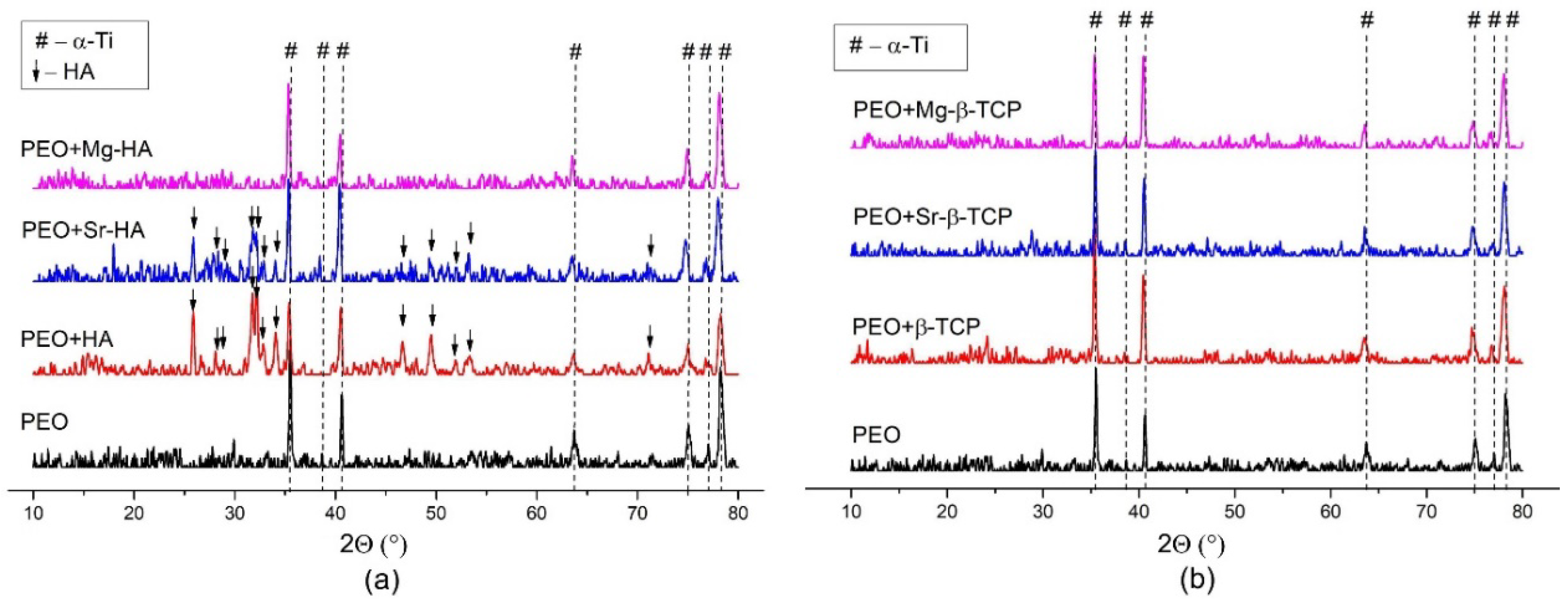
3.2. Coating Phase Composition

In the XRD patterns of all composite coatings, we observed metallic substrate α-Ti characteristic peaks at 2θ = 35.24° (corresponding to 100 plane reflection), 38.39° (002), 40.29° (101), 63.24° (110), 74.52° (200), 76.47° (112) and 77.71° (201) (Figure 3). In the patterns of HA and Sr-HA RFMS coatings, we observed sharp peaks in hydroxyapatite Ca5(PO4)3(OH) at 2θ = 25.85° (002), 31.77° (121), 32.18° (112), 32.91° (300), 34.05° (202), 46.69° (222) and 49.46° (213) (Figure 3a). We also identified less intense hydroxyapatite peaks at 2θ = 28.11° (102), 28.93° (210), 52.07° (402), 53.09° (141) and 70.79° (503). Considering the absence of the reflection from the (211) plane, which is the strongest line of HA phase and the width and sharpness of the observed peaks, we suggest that composite coatings’ RFMS with HA and Sr-HA are predominantly amorphous coatings, with the presence of the peaks in the HA crystal phase.

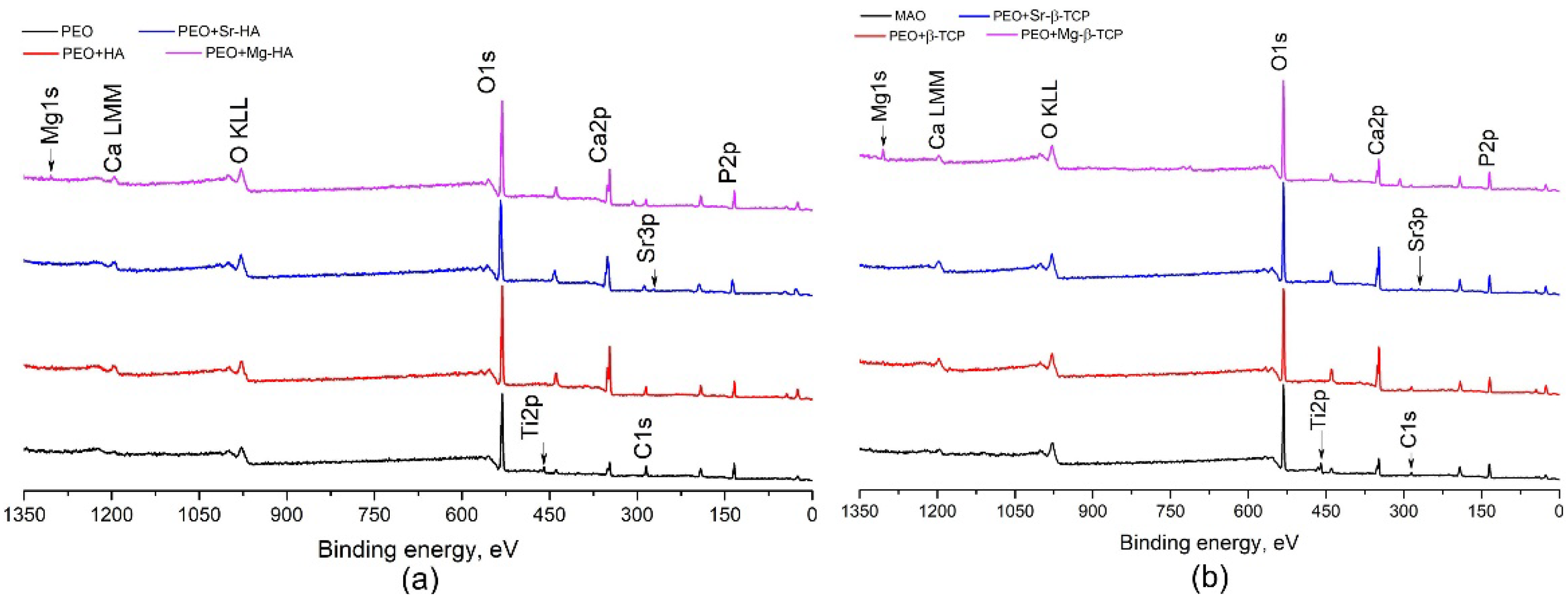
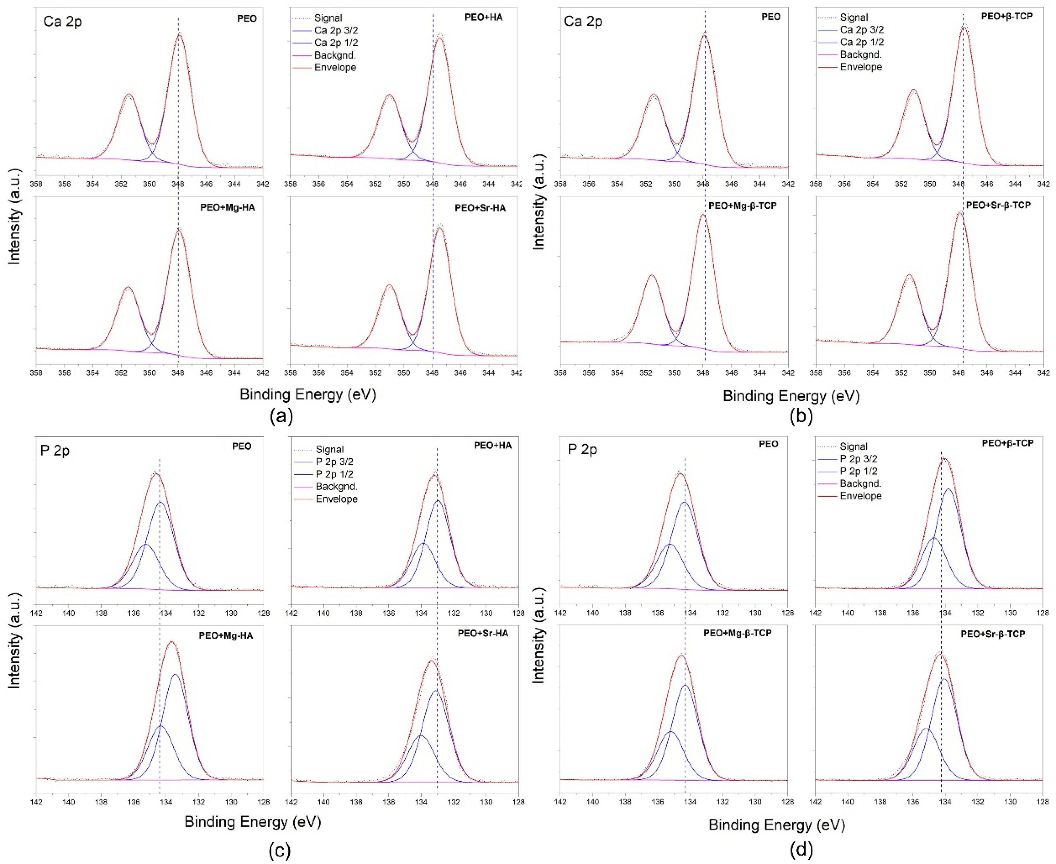
3.3. Coating Chemical Composition

Chemical composition of composite coatings is presented in Table 2. The compositions of coatings correspond to the chemical composition of PEO electrolyte and RFMS targets and are generally represented by Ca, P and O. Coatings’ RFMS with Sr- and Mg-substituted targets contain Sr and Mg, respectively.
It should be noted that CaP PEO coatings are generally calcium-deficient and characterized by Ca/P = 0.34 ± 0.02. The RFMS upper coating increases the Ca/P ratio. The Ca/P ratio varies in the following progression: PEO < PEO + Mg-β-TCP < PEO + Sr-β-TCP < PEO + Mg-HA < PEO + β-TCP < PEO + Sr-HA < PEO + HA. Moreover, for both HA and β-TCP, the Ca/P ratio is greater for Sr-substituted upper coatings compared with Mg-substituted coatings.
In the XPS spectra of PEO coating, we observed typical O1s, Ti2p, Ca2p, C1s, P2p and Auger’s peaks corresponding to O KLL and Ca LMM (Figure 4). The Ti2p peak appears only in PEO CaP coatings’ spectra at the following binding energy: Ti2p3/2 = 459.28 eV. Generally, this peak recognizes O–Ti–O of TiO2 [23]. In composite coatings’ spectra, Ti2p is not identified due to the RFMS thin CaP upper coating. In the spectra of composite coatings sputtered with Sr- and Mg-substituted HA and β-TCP, we revealed the small peaks in Sr and Mg, respectively. The typical XPS spectra of Ca2p and P2p core levels of the coatings are shown in Figure 5. The corresponding BE values of Ca2p3/2 and P2p3/2 of the coatings are listed in Table 3. Generally, different CaP materials show peaks at similar binding energies in the XPS spectra [24,25]. Peaks overlapping makes it difficult to distinguish different CaP phases in composite material. Peaks at 347.46, 133.00 and 347.46, 133.00 eV in the spectra of PEO + β-TCP and PEO + Sr-β-TCP, respectively, correspond to Ca 2p3/2 and P 2p3/2 in Ca5(PO4)(OH). This correlates with the XRD data. XPS analysis revealed the following relations for composite coatings (Table 3):
  • PEO and PEO + Mg-β-TCP coatings show the highest P2p binding energy;
  • PEO + Mg-β-TCP and PEO+Mg-HA coatings show the highest Ca2p binding energy;
  • Binding energy increases by the following progression: PEO + Mg-β-TCP < PEO + Sr-β-TCP < PEO + β-TCP and PEO + Mg-HA < PEO + Sr-HA < PEO + HA.

3.4. Young’s Modulus

RFMS CaP upper coating significantly enhances PEO + Mg-HA, PEO + Sr-HA and PEO + β-TCP Young’s modulus compared with the PEO subcoating (Table 4). It is important to note that the Young’s modulus of all coatings under study varies in the range 15–37 GPa, which corresponds with the nanoindentation modulus of human bone [26].

4. Conclusions

Composite PEO+RFMS coatings were characterized by the multileveled roughness, increased Ca/P ratio and Young’s modulus (PEO + Mg-HA, PEO + Sr-HA, PEO + β-TCP). The upper RFMS CaP coating forms a thin layer over the PEO sub-coating spherulites. The RFMS of different CaP and ion-substituted CaP provides various coating crystallinities and are potentially beneficial in adjustable biodegradation and osseointegration. Moreover, the sputtering of ion-substituted CaP targets makes it possible to introduce into the composition of the coatings elements that bone tissue growth-stimulating (Mg) and suppress the resorptive activity of osteoclasts (Sr).

Author Contributions

A.K.: conceptualization, data curation, funding acquisition, supervision, investigation, methodology, validation, writing—original draft, writing—review and editing; G.D.: nanoindentation, data curation; validation; writing—review and editing; A.V.: PEO subcoating formation, data curation; validation; A.F.: upper coatings’ formation by RFMS, data curation; validation; N.K.: synthesizing the powders of pure hydroxyapatite (HA), Sr-HA, Mg-HA by microwave-assisted method, data curation; validation; A.G.: synthesizing the powders of pure hydroxyapatite (HA), Sr-HA, Mg-HA by microwave-assisted method, data curation; validation; E.S.: upper coatings’ formation by RFMS, data curation; validation; Y.Z.: X-ray photoelectron spectroscopy (XPS), data curation; validation; S.T.: conceptualization, resources, funding acquisition, supervision, validation. All authors have read and agreed to the published version of the manuscript.

Funding

This work was supported by the Tomsk Polytechnic University Competitiveness Enhancement Program project VIU-School of Nuclear Science and Engineering-204/2019 and project VIU-SEC B.P. Veinberg-196/2020.

Acknowledgments

Our gratitude to Liga Stipniece and Janis Locs from Riga Technical University (Riga, Latvia) for the synthesis of the β-TCP, Mg-β-TCP, Sr-β-TCP powders. We are grateful to V.P. Ignatov for consultations on the preparation of CaP electrolyte for PEO and valuable advice on the discussion of the experimental results. The authors are grateful to the Resource Centre “Materials Science Shared Center”, part of the “Tomsk Regional Common Use Center (TRCUC)” of Tomsk State University, for XRD measurements, and the Resource Centre “Physical Methods of Surface Investigation” of Saint-Petersburg State University Research Park for XPS measurements.

Conflicts of Interest

The authors declare no conflict of interest.

References

  1. Liu, F.; Song, Y.; Wang, F.; Shimizu, T.; Igarashi, K.; Zhao, L. Formation characterization of hydroxyapatite on titanium by microarc oxidation and hydrothermal treatment. J. Biosci. Bioeng. 2005, 100, 100–104. [Google Scholar] [CrossRef] [PubMed]
  2. Parfenov, E.; Parfenova, L.; Mukaeva, V.; Farrakhov, R.; Stotskiy, A.; Raab, A.; Danilko, K.; Rameshbabu, N.; Valiev, R. Biofunctionalization of PEO coatings on titanium implants with inorganic and organic substances. Surf. Coat. Technol. 2020, 404, 126486. [Google Scholar] [CrossRef]
  3. Yang, W.; Wang, P.; Guo, Y.; Jiang, B.; Yang, F.; Li, J. Microstructure and corrosion resistance of modified AZ31 magnesium alloy using microarc oxidation combined with electrophoresis process. J. Wuhan Univ. Technol. Sci. Ed. 2013, 28, 612–616. [Google Scholar] [CrossRef]
  4. Rehman, Z.U.; Choi, D.; Koo, B.H. A three layer corrosion protection system for Mg–9Al–Zn alloy offered by complex fluoride ions and precipitates-based electrolytic oxidation. Surf. Coat. Technol. 2020, 393, 125804. [Google Scholar] [CrossRef]
  5. Ur Rehman, Z.; Heun Koo, B.; Choi, D. Influence of complex SiF62− Ions on the PEO coatings formed on Mg–Al6–Zn1 alloy for enhanced wear and corrosion protection. Coatings 2020, 10, 94. [Google Scholar] [CrossRef] [Green Version]
  6. Ur Rehman, Z.; Choi, D. Investigation of ZrO2 nanoparticles concentration and processing time effect on the localized PEO coatings formed on AZ91 alloy. J. Magnes. Alloy. 2019, 7, 555–565. [Google Scholar] [CrossRef]
  7. Gu, Y.; Xiong, W.; Ning, C.; Zhang, J. Residual stresses in microarc oxidation ceramic coatings on biocompatible AZ31 magnesium alloys. J. Mater. Eng. Perform. 2011. [Google Scholar] [CrossRef]
  8. Akin, F.A.; Zreiqat, H.; Jordan, S.; Wijesundara, M.B.J.; Hanley, L. Preparation and analysis of macroporous TiO2 films on Ti surfaces for bone–tissue implants. J. Biomed. Mater. Res. Part A 2001, 57, 588–596. [Google Scholar] [CrossRef]
  9. Yavari, S.A.; Necula, B.S.; Fratila-Apachitei, L.E.; Duszczyk, J.; Apachitei, I. Biofunctional surfaces by plasma electrolytic oxidation on titanium biomedical alloys. Surf. Eng. 2016, 32, 411–417. [Google Scholar] [CrossRef] [Green Version]
  10. Krząkała, A.; Kazek-Kęsik, A.; Simka, W. Application of plasma electrolytic oxidation to bioactive surface formation on titanium and its alloys. RSC Adv. 2013, 3, 19725. [Google Scholar] [CrossRef]
  11. Barati Darband, G.; Aliofkhazraei, M.; Hamghalam, P.; Valizade, N. Plasma electrolytic oxidation of magnesium and its alloys: Mechanism, properties and applications. J. Magnes. Alloy. 2017, 5, 74–132. [Google Scholar] [CrossRef]
  12. Jiang, B.L.; Wang, Y.M. Plasma electrolytic oxidation treatment of aluminium and titanium alloys. In Surface Engineering of Light Alloys; Elsevier: Amsterdam, The Netherlands, 2010; pp. 110–154. [Google Scholar]
  13. Depla, D.; Mahieu, S.; Greene, J.E. Sputter Deposition Processes. In B Handbook of Deposition Technologies for Films and Coatings; Elsevier: Amsterdam, The Netherlands, 2010; pp. 253–296. [Google Scholar]
  14. Juhasz, J.A.; Best, S.M. Surface modification of biomaterials by calcium phosphate deposition. In Surface Modification of Biomaterials; Elsevier: Amsterdam, The Netherlands, 2011; pp. 143–169. [Google Scholar]
  15. Park, S.-Y.; Choe, H.-C. Mn-coatings on the micro-pore formed Ti–29Nb–xHf alloys by RF-magnetron sputtering for dental applications. Appl. Surf. Sci. 2018, 432, 278–284. [Google Scholar] [CrossRef]
  16. Hwang, I.-J.; Choe, H.-C. Surface morphology and cell behavior of Zn-coated Ti–6Al–4V alloy by RF-sputtering after PEO-treatment. Surf. Coat. Technol. 2019, 361, 386–395. [Google Scholar] [CrossRef]
  17. Lu, J.; Yu, H.; Chen, C. Biological properties of calcium phosphate biomaterials for bone repair: A review. RSC Adv. 2018, 8, 2015–2033. [Google Scholar] [CrossRef] [Green Version]
  18. Urquia Edreira, E.R.; Wolke, J.G.C.; Aldosari, A.A.; Al-Johany, S.S.; Anil, S.; Jansen, J.A.; van den Beucken, J.J.J.P. Effects of calcium phosphate composition in sputter coatings on in vitro and in vivo performance. J. Biomed. Mater. Res. Part A 2015, 103, 300–310. [Google Scholar] [CrossRef]
  19. Eliaz, N.; Metoki, N. Calcium phosphate bioceramics: A review of their history, structure, properties, coating technologies and biomedical applications. Materials 2017, 10, 334. [Google Scholar] [CrossRef] [Green Version]
  20. Zeng, J.; Guo, J.; Sun, Z.; Deng, F.; Ning, C.; Xie, Y. Osteoblastic and anti-osteoclastic activities of strontium-substituted silicocarnotite ceramics: In vitro and in vivo studies. Bioact. Mater. 2020, 5, 435–446. [Google Scholar] [CrossRef]
  21. BS EN ISO 14577 International Organization for Standardization. Metallic Materials: Instrumented Indentation Test for Hardness and Materials Parameters. Verification and Calibration of Testing Machines; ISO: Geneva, Switzerland, 2002. [Google Scholar]
  22. Kozelskaya, A.I.; Kulkova, S.E.; Fedotkin, A.Y.; Bolbasov, E.N.; Zhukov, Y.M.; Stipniece, L.; Bakulin, A.V.; Useinov, A.S.; Shesterikov, E.V.; Locs, J.; et al. Radio frequency magnetron sputtering of Sr- and Mg-substituted β-tricalcium phosphate: Analysis of the physicochemical properties and deposition rate of coatings. Appl. Surf. Sci. 2020, 509, 144763. [Google Scholar] [CrossRef]
  23. Callen, B.W.; Lowenberg, B.F.; Lugowski, S.; Sodhi, R.N.S.; Davies, J.E. Nitric acid passivation of Ti6A14V reduces thickness of surface oxide layer and increases trace element release. J. Biomed. Mater. Res. 1995, 29, 279–290. [Google Scholar] [CrossRef]
  24. França, R.; Samani, T.D.; Bayade, G.; Yahia, L.; Sacher, E. Nanoscale surface characterization of biphasic calcium phosphate, with comparisons to calcium hydroxyapatite and β-tricalcium phosphate bioceramics. J. Colloid Interface Sci. 2014, 420, 182–188. [Google Scholar] [CrossRef]
  25. Lu, H.B.; Campbell, C.T.; Graham, D.J.; Ratner, B.D. Surface characterization of hydroxyapatite and related calcium phosphates by XPS and TOF-SIMS. Anal. Chem. 2000, 72, 2886–2894. [Google Scholar] [CrossRef]
  26. Wu, D.; Isaksson, P.; Ferguson, S.J.; Persson, C. Young’s modulus of trabecular bone at the tissue level: A review. Acta Biomater. 2018, 78, 1–12. [Google Scholar] [CrossRef]
Figure 1. SEM micrographs of PEO CaP subcoating (a) and PEO + RFMS HA (b), Sr-HA (c), Mg-HA (d), β-TCP (e), Sr-β-TCP (f) and Mg-β-TCP (g) composite coatings.
Coatings 10 01113 g001
Figure 2. AFM images of CaP PEO (a) and composite PEO + RF coatings sputtered with HA (b), Sr-HA (c), Mg-HA (d), β-TCP (e), Sr-β-TCP (f), and Mg-β-TCP (g) targets.
Coatings 10 01113 g002
Figure 3. XRD patterns of CaP PEO and composite PEO + RF coatings sputtered with (a) HA, Sr-HA, Mg-HA; (b) β-TCP, Sr-β-TCP, Mg-β-TCP targets.
Coatings 10 01113 g003
Figure 4. The XPS survey spectra for the CaP PEO (black line on Figure 4a,b) and composite HA (a) and β-TCP (b) RFMS coatings.
Coatings 10 01113 g004
Figure 5. High-resolution XPS spectra of Ca 2p (a,b) and P 2p (c,d) core levels of composite CaP coatings.
Coatings 10 01113 g005
Table 1. Coating thickness.
GroupPEO Subcoating Thickness, μmRFMS Upper Coating Thickness, μmTotal Composite Coating Thickness, μm
PEO35 ± 1.735.0 ± 1.7
PEO + HA36 ± 1.02.4 ± 0.138.4 ± 1.1 *
PEO + Sr-HA36 ± 1.01.3 ± 0.1 37.3 ± 1.1
PEO + Mg-HA34 ± 0.51.1 ± 0.1 35.1 ± 0.6
PEO + β-TCP35 ± 1.50.7 ± 0.135.7 ± 1.6
PEO + Sr-β-TCP36 ± 1.51.0 ± 0.1 37.0 ± 1.6
PEO + Mg-β-TCP35 ± 1.50.6 ± 0.135.6 ± 1.6
* significant differences with PEO (p < 0.05); significant differences between groups of the β-TCP and X-β-TCP coatings and HA and X-HA coatings, where X is Mg or Sr (p < 0.05).
Table 2. Chemical composition of CaP composite coatings.
SampleThe Content of Elements in the Coating (at.%)
OCaPTiCSrMgCa/P
PEO61.5 ± 0.66.0 ± 0.317.6 ± 0.23.7 ± 0.311.4 ± 1.40.34 ± 0.02
PEO + HA54.9 ± 0.8 *17.9 ± 0.6 *14.7 ± 0.5 *12.5 ± 0.51.22 ± 0.06 *
PEO + Sr-HA57.7 ± 1.8 *17.1 ± 0.5 *17.0 ± 0.57.7 ± 2.80.5 ± 0.04 *1.01 ± 0.04 *
PEO + Mg-HA60.0 ± 2.013.4 ± 0.4 *17.4 ± 0.67.9 ± 2.91.3 ± 0.3 *0.77 ± 0.04 *
PEO + β-TCP59.4 ± 1.0 *15.1 ± 0.1 *16.2 ± 0.4 *9.3 ± 1.4 0.93 ± 0.02 *
PEO + Sr-β-TCP58.3 ± 2.513.2 ± 0.8 *19.0 ± 1.3 *9.0 ± 4.70.5 ± 0.2 *0.70 ± 0.06 *
PEO + Mg-β-TCP62.8 ± 0.5 *8.5 ± 0.1 *18.3 ± 0.3 *7.4 ± 1.2 *2.9 ± 0.4 *0.46 ± 0.01 *
* significant differences with PEO (p < 0.05); significant differences between groups of the X-β-TCP and X-HA coatings, where X is Mg or Sr (p < 0.05).
Table 3. Binding energy values of the Ca2p3/2 and P2p3/2 XPS peaks.
CoatingCa 2p3/2 (eV)P 2p3/2 (eV)
PEO347.88134.31
PEO + HA347.46133.00
PEO + Sr-HA347.44133.10
PEO + Mg-HA347.92133.43
PEO + β-TCP347.59133.80
PEO + Sr-β-TCP347.87134.07
PEO + Mg-β-TCP347.97134.31
Table 4. Young’s modulus of CaP PEO and composite coatings.
CoatingEIT, GPa
PEO15.4 ± 3.8
PEO + HA21.3 ± 3.7
PEO + Sr-HA36.6 ± 9.5 *
PEO + Mg-HA29.8 ± 6.8 *
PEO + β-TCP25.6 ± 5.8 *
PEO + Sr-β-TCP19.5 ± 4.1
PEO + Mg-β-TCP17.4 ± 3.2
* significant differences with PEO, p < 0.05; significant differences between groups of the β-TCP and X-β-TCP coatings and HA and X-HA coatings, where X is Mg or Sr, p < 0.05.
Publisher’s Note: MDPI stays neutral with regard to jurisdictional claims in published maps and institutional affiliations.

