Abstract
Successive impingement of droplets after refining in supersonic plasma jet generally yields a submicron-sized lamellar coating with excellent comprehensive properties. Nevertheless, physical insight into the flattening and rapid solidification with crystallization behavior of supersonic impingement of refined droplets is difficult to understand. In this research, the content of refinement droplets reached 90% and displayed the multi-scale distribution of equiaxed grains. The boundary migration of equiaxed grains and anisotropic coalescence was found in the dynamic temperature gradient. Furthermore, an optimized model was established in order to accurately reproduce the multi-physical coupling process of supersonic impingement of single or two refined droplets, which was based on the numerical calculation of nonlinear equations (including the Mass and momentum, energy balance, Cahn–Hilliard, phase-field and orientational field equations). The size distribution and growth orientation of columnar grains within single or two flattened droplets were in good agreement with the experimental results. Epitaxial growth of columnar grains was found in the two-flattened droplet interface during the extremely rapid cooling stage. This optimized model could be an effective method in predicting the flattening and solidification with crystallization behavior of droplets during plasma spraying.
1. Introduction
The widely used industrial manufacturing processes usually involve the growth of single crystal, metal additive manufacturing, laser-assisted thin film and thermal spray coating [1,2]. Generally, the thermal spray process can be realized by rapidly quenching techniques. Due to the non-equilibrium driving effects, it is possible to produce supersaturated solid-solutions, quasi-crystals, metastable crystalline, amorphous and grain-refined materials [3,4]. The thermal sprayed coating is associated with the rapid solidification and crystallization behavior of flattened droplets [5,6,7]. These flattened droplets (splats) can serve as the building blocks of coating, which consists of numerous columnar grains that are originated from the heterogeneous nucleation of droplets and competitive growth under the thermal flow direction [8]. In addition, the crystallographic orientation of columnar grains is another important factor that affects the shape of grains. Some researchers showed that the thermal–mechanical properties of coatings were closely related to crystallographic orientation [9]. The crystallographic orientation is determined by the solidification of droplets [10,11]. During plasma spraying, the solidification rate of ceramic droplets is approximately 104~106 K/s. For a metal droplet, the solidification rate is up to 106~108 K/s [12]. Our previous study suggested that the average height and width of columnar grains presented submicron or nano-scale crystallographic texture when the solidification rate of ceramic supersonic in-flight droplets drastically increased to 109 K/s [13,14]. The rapid solidification rate resulted in the formation of fine-lamellar-structured coating with multi-scale crystallographic texture, which exhibited excellent comprehensive performances (e.g., bonding strength, heat temperature resistance, anti-oxidation and thermal shock resistance) [15,16,17].
Although the crystallographic orientation can be studied by in situ heating high-resolution transmission electron microscopy (HRTEM) technology [11,13], the dynamic growth behavior of multi-scale grains of ceramic droplets is still scarcely observed by some experimental methods. Physical insight into the growth and formation process of multi-scale grains within the fine-lamellar structure at extremely rapid solidification is great of importance and is necessary. The phase-field method is referred to as a diffuse interface one and is firstly proposed by investigating the non-linear transition behavior of materials [18]. The involved mathematical equations originated from the non-linear dynamics theory [19]. Over the past three decades, this method has been adopted to simulate the formation and evolution of microstructure (e.g., dendritic and eutectic growth) during the solidification or phase transformation of materials [20,21]. On account of the category of moving boundary problems, the solid–liquid contact area and diameter scale of second phases at three grains boundaries were studied [22,23]. Furthermore, some researchers also took into account the orientation behavior of anisotropic growth of multi-scale grains and the evolution of grain boundaries [24,25,26]. Nevertheless, the current phase-field models usually ignore the compatibility between the model parameter and physical phenomenon. The collision and growth modes of multi-scale grains at the deeply supercooling are still not fully understood for one supersonic droplet impacting on a substrate.
The impacting phenomenon of a supersonic droplet involves the coupling multi-physics. Cahn and Hilliard [27] proposed the use of the phase-filed model to solve the problem of phase separation. Subsequently, Jacqmin [28] reported the combination of Cahn–Hilliard and Navier–Stokes equations to apply in gas–liquid two-phase flow, and derived the surface tension expression in the phase field. Pasandideh–Fard and P. et al. [29,30] established the mathematical model of the flattening and solidification processes, which was known as the phase transformation Coupled Level Set-VOF (CLSVOF) model from liquid phase to solid phase. However, the method is needed to track the free interface and is unable to describe the nucleation and dynamic growth of the grains within solidified splats. Recently, a coupled CFD and diffuse interface model have been developed to reproduce the solidification microstructure formation of supersonic YSZ droplets in our previous works [31,32,33]. Meanwhile, a refinement phenomenon of in-flight droplets after melting and fragmentizing is found in the supersonic plasma spraying process. The droplet size was smaller and had an extremely rapid solidification rate, resulting in the formation of fine-lamellar structured coatings [34]. Nevertheless, the flattening morphology and crystallization texture of single or sequential droplets after refining in supersonic plasma jet are not validated systematically.
Based on the above background, in the present work, an experimental study was carried out in order to study the refinement of YSZ droplets and crystallization texture. Furthermore, an optimized numerical model accurately reproduced the coupling multi-physics process after impacting supersonic refined droplets. The relationship between the solidification rate and crystallographic orientation of grains is elaborated in order to clarify the underlying growth mechanism of equiaxed or columnar grains of flattened supersonic droplets at an extremely rapid solidification rate.
2. Experimental and Mathematical Methods
2.1. Materials and Experimental Methods
Two methods were employed to collect the supersonic droplets via a water bath and a V-shaped shield. The experimental set-up is shown in Figure 1. The corresponding coating was deposited by a high efficiency supersonic atmospheric plasma spraying (SAPS) system. The temperature and velocity of in-flight droplets were measured by Spray Watch 2i online monitoring system (Oseir, Finland). Meanwhile, the spray-dried and sintered ZrO2-8 wt % Y2O3 (YSZ) powders were used as the starting feedstock materials. The feedstock powder after sieving had a near-perfect spherical morphology with a particle size of 25–35 μm and the average size was approximately 30 μm. The grain size of feedstock powder was in the range of 100 to 900 nm, as shown in Figure 2a–c [35,36]. The morphology of collected powder in the water bath is shown in Figure 2d–f. Compared with the feedstock powder as shown in Figure 2a–c, the size of collected powder in the water bath significantly decreased to 0.5–6 μm. The thermal interaction between the in-flight droplets and plasma jet in SAPS directly caused the fragmentation of feedstock powder. Meanwhile, the grain size of the collected powder was greatly reduced to 100–200 nm.
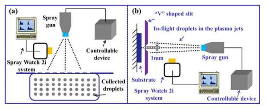
Figure 1.
Collection schematic of in-flight droplets via both techniques: (a) experimental set-up of water collection; (b) a V-shaped shield of single flattened droplet.
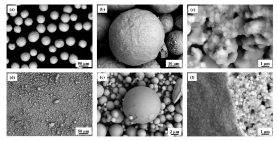
Figure 2.
SEM images of powder used for plasma spray: (a) feedstock powder after sieving; (b) high-magnification image of single feedstock powder; (c) grain morphology in the inside of feedstock powder; (d) refinement powder morphology after water collection; (e) high-magnification morphology of single refinement powder; (f) grain morphology in the inside of refinement powder.
2.2. Specimen Characterization
The thermal etching method was used to study the morphology of the grains, which was carried out at a high temperature of 1250 °C at 3 h and was naturally decreased to 25 °C [35]. The morphology of thermal etched coating was obtained using scanning electron microscopy (SEM, VEGAII XMU, Tescan, BrNo, Czech Republic). Furthermore, the growth behavior of grains was analyzed by high-resolution transmission electron microscopy (HRTEM, JEM-2100F, JEOL, Tokyo, Japan). The thickness reduction of the HRTEM specimen was usually ground and polished with sandpaper. Then, a Gatan 691 precision ion polishing system (Gatan Inc., Pleasanton, CA, USA) was used to further achieve the thin region. In addition, the crystallographic texture within splat was further observed using EBSD technology (Oxford, UK), which was performed on the splat surface at the acceleration voltage of 15 kV.
2.3. Mass, Momentum, Energy and Phase-Field Equations of Droplet Impact
The impingement process of the supersonic in-flight droplet is a complex fluid flow, heat transfer, solidification, nucleation and oriented growth of grains [32,33]. In order to accurately reproduce this process, the droplet flow and solidification are firstly analyzed, and then added the nucleation and oriented growth of grains. For the fluid flow of the flattening process, a phase-field method is used to describe the evolution of gas–liquid interface. The fixed grids are directly handled a moving free surface as encountered in YSZ droplet spreading. The phase-field parameter is distinguished into the liquid () and gas phase (). The Cahn–Hilliard equation will be illustrated the evolution of , as follows:
where is velocity, the diffusion strength, the chemical potential, the bulk free energy density, the interfacial thickness, surface tension, a constant (). The system energy finally reaches an equilibrium statue by the equation .
The primary variable is velocity and pressure in the flow field. For the incompressible Newtonian fluids of YSZ droplet, the mass and momentum equations are as follows:
where is the mechanical pressure, Newtonian stress tensor, local gravity acceleration, the chemical potential, denotes the gas–liquid surface tension. The thermophysical properties of YSZ materials are identified as the function of the phase-field parameter . The expression of density and dynamic viscosity are and , respectively. It is worth noting that the thermal source in Equation (4) promotes the nucleation and oriented growth of grains when solidification of YSZ droplet. It is expressed as . The liquid fraction of the thermal source is equivalent to One constant is 0.001, and the other represents the convection heat transfer in the mushy zone.
For the heat transfer with phase change during solidification, an energy equation is required and shown in Equation (5). It is related to the surface temperature and in-flight velocity of the YSZ droplet. Moreover, some thermophysical properties of YSZ materials are taken into account in Equation (5), including density, specific heat and thermal conductivity. In particular, in Equation (5) means the release of latent heat. When the phase-field parameter , equals zero. When , the is updated.
2.4. Phase-Field Equation for Crystallization Behavior
For the crystallization behavior when solidification, a phase-field model is employed to study this physical process. The free energy of the system is given by:
where is the bulk free energy density [16]. is the anisotropic gradient energy coefficient. The second term accounts for the energy penalty within the interface. The latter terms ensure the motion and stable of grain boundaries. and specify the strength of the coupling between and . is the inclination angle of the solid–liquid interface () with respect to the axis, which is defined as .
Based on the bulk free energy density [25,36], the kinetic evolution of solid–liquid order parameter () ranging from the liquid () to the solid phase () is described as follows:
where is the interface attachment kinetic times. specifies the coupling between phase-field and diffusion fields. refers to the dimensionless temperature. , , are melting temperature, latent heat and specific heat capacity, respectively. In particular, in Equation (7) prompts the stable of grain boundaries, represents the rotation and migration of grain boundaries during solidification.
In addition, the orientational field of grains growth is given by:
where is the inverse mobility function, . represents grain rotation. is grain boundary mobility. is a second-order tensor and is given as follows:
Actually, the crystal growth is accompanied by the anisotropy feature. and are used to describe this anisotropic gradient energy and can be described by and , respectively.
2.5. Boundary Conditions
The boundary condition of the different physical processes is related to the existing substrate. For the droplets fluxion and phase change behavior, the substrate is set as inexistent. When considering of heat transfer process, these boundaries conditions of both the droplet and substrate area are regarded as adiabatic. The setting up of boundary conditions is shown in Figure 3a. The order parameter on the substrate surface satisfies the following equation:
where is the free energy density, and it is expressed as , is the unit normal pointing to the wall, gives the liquid–solid interfacial tension and produces the gas–solid interfacial tension , the static contact angle through Young’s equation .
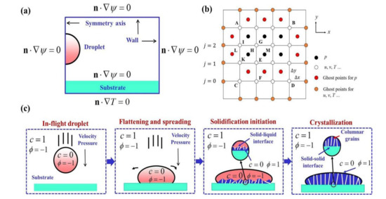
Figure 3.
Parameters definition of calculation process: (a) boundary conditions; (b) a modified grid during discretization; (c) order parameter distribution of droplet after impacting on the substrate.
2.6. Numerical Procedures
A finite difference method is used to explicitly discretize the above equations, and the upwind arithmetic for the convective process will be handled in the numerical modeling. Unlike the analytical solution, which gives precise values of variables at every point in a domain of interest, the numerical solution provides solutions at discrete points of the domain. The first step in any numerical analysis must be to select these points. This may be performed by subdividing the medium of interest into a number of small regions and assigning to each cell vertex a reference point in Figure 3b. The exact differential equations will be reduced to algebraic equations after approximating the derivative terms. Moreover, some ghost points with red and orange colours are modified during discretization. When considering boundary points, it is unchanged in the discretized equations. The droplet bottom at j = 1 is no-slip condition, while j = 0 represents the nodes on the substrate surface. A thermal contact resistance layer is taken into account at the flattened droplet and substrate interface, which corresponds to both areas j = 1 and j = 0. The two-order parameters definition of droplet after impacting on a substrate is shown in Figure 3c. As seen from Figure 3c, the pair of and represents the surrounding atmosphere of the in-flight droplet, and mean in-flight droplet, and are the grains when solidification. Meanwhile, the time step of the computation process is set as the order of 10−13 s. Moreover, for the solidification stage of heat transfer, the one-time loop is defined as the evolution of and during c ≤ 0.5. In order to accelerate computation, parallel programming based on OpenMP (version 2.0) is applied in this work.
3. Results and Discussion
3.1. Refinement of a Supersonic Ceramic Droplet
The microstructure and properties of the coating are related to flattening and rapid solidification with crystallization behavior of supersonic droplets. The spray parameters and corresponding temperature and velocity of droplets are listed in Table 1. As seen from Table 1, owing to a Laval nozzle with an internal injection port, the temperature and velocity of supersonic droplets increased with the increase of spray power. The flattened droplets (splats) gradually converted from net-shaped into finger-shaped splashing morphology in Figure 4a–c. Our previous study showed that the net-shaped splat was multilayered and the finger-shaped one was a monolayered structure, respectively [14]. Furthermore, as seen from Figure 4a–c, some refined splats formed and were located in the periphery of splashing morphology. However, the corresponding structure was obviously evolved into a disk-shaped one. Based on the isovolumetric feature of both spherical droplets and splats, the diameter of refined droplets was calculated and less than 5 μm through a 3D Laser Scanning Microscope. After statistical analysis, the content of fragmented droplets with different temperatures or velocities was 75.16%, 86.32% and 90.21%, respectively. These results suggested that the simultaneous improvement of temperature and velocity of in-flight droplets was beneficial to the fragmentation of droplets.

Table 1.
Spray parameters for 8 wt % YSZ splat and coating.
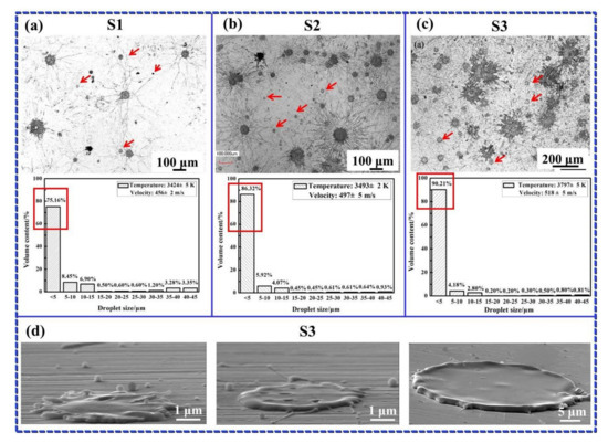
Figure 4.
Morphology and percentage of splats at different in-flight behavior: (a) S1; (b) S2; (c) S3; (d) high-magnification images of refinement S3 splat.
The size reduction and morphology change of splats suggested that the in-flight droplets were melted and broken up in the supersonic plasma jet via the interaction of energy, which was dependent on the critical threshold between the hydrodynamic pressure and added one. The added pressure originated from the surface tension of the droplet [34]. It was firstly continued to the deformation of the droplet without disintegrating in the fragmentized process. When the added pressure was inferior to the hydrodynamic one, the fragmentation of the droplet occurred. When the droplet morphology was a spherical shape, the added pressure could be described by Young–Laplace () [34,37]. The calculated added pressure was 5.7 × 10⁴ Pa based on a YSZ droplet with an average size of 30 μm. Nevertheless, the hydrodynamic pressure provided by drag force was described as follows [38]:
where is the drag force, is the density of plasma jet, is the drag coefficient () [39], is Reynolds number, is the velocity of plasma jet obtained by CFD-ACE + V2009.0 (ESI GROUP, America) simulation, is the in-flight velocity of YSZ droplet obtained by Spray Watch 2i system and Re is Reynolds number of YSZ droplet () [40,41]. Our previous work showed that the hydrodynamic pressure was significantly larger than the added pressure (5.7 × 10⁴ Pa), indicating that the breakup of YSZ droplet occurred in the supersonic plasma jet [34].
3.2. Grain Size Distribution and Crystallographic Orientation of Refined Droplet
Based on the content of refined droplets was in the majority (>90%) via the above experimental collection in Figure 4, which was regarded as a typical droplet to study in the following experiments and simulations. Figure 5 shows the texture and crystallographic orientation of refined droplets after flattening and solidification. The inverse pole figure (IPF) and an orientation map of refined droplets are shown in Figure 5a. As seen from Figure 5a, the grain size of splat was ranging from 0.05 µm to 0.51 µm. According to the statistical results, the content of grains with a size of 0.15 µm reached 14% and was much higher than other grains. The small-sized grains originated from the rapid solidification rate of supersonic in-flight droplets after impacting on a substrate. Moreover, these grains had preferential growth along the [001] direction of the X-axis. Figure 5b depicts the surface morphology of the coating after thermal etching at 1250 °C for 3 h. It can be seen from Figure 5b that most grain sizes were distributed in the range of 100–200 nm and the percentage was 15%. Additionally, some nano-grains were also verified by TEM as shown in Figure 5c. The selected area electron diffraction (SAED) patterns of nano-grains at the “A” position suggested that the nano-grains belonged to the tetragonal phase with preferential growth along the direction. The corresponding crystallographic orientation angle () was π/4.
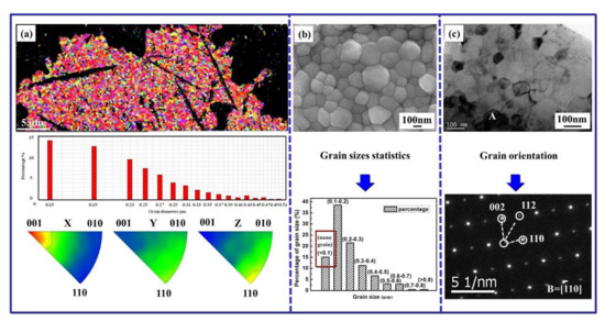
Figure 5.
(a) Inverse pole figure (IPF), grain sizes distribution and IPF orientation maps of single-layered splat surface vertical to the substrate (normal direction); (b) Morphology of equiaxed grains and grain sizes statistics within coating after thermal etching at 1250 °C for 3 h; (c) TEM image of equiaxed grains and corresponding selected area electron diffraction (SAED) patterns.
Figure 6 provides the simulation results of the crystallization process and final morphology of equiaxed grains in one flattened YSZ droplet (splat). The average in-flight temperature and velocity of YSZ droplet was (3797 ± 5) K and (518 ± 5) m/s, respectively. The corresponding dimensionless temperature was calculated as 0.59 according to the physical parameter of YSZ materials. These experimental values were considered as the initial conditions and inputted into this model. It can be seen from Figure 6a,b that the temperature of YSZ droplet gradually decreased during solidification and accompanied by the competitive growth of equiaxed grains. Subsequently, the smaller grains were inclined to larger ones and some obvious thermal interaction zones were observed at μs. These large-sized grains collided upon each other, resulting in the formation of grain boundaries. Then the motion of grain boundaries occurred during the coarsening and fusion process. With the aim of simulating four-fold anisotropy of equiaxed grains, the crystallographic orientation angle for each solid seed was initially assigned, while it was limited to the scope of [26,42]. Figure 6c shows the grain orientation at different times. As seen from Figure 6c, the grain fusion was observed in a relatively low and had a small orientation mismatch. However, in the case of a large orientation mismatch between two impinging grains, the grain boundary was more stable. With the solidification time (t) was sustained up to 0.375 μs, the grain growth was in a steady-state and the final grain size was in the range of 30–120 nm. The above phase-field model further confirmed the accuracy of experimental results.

Figure 6.
(a) Temperature distribution of equiaxed grains within flattened supersonic droplet during extremely rapid solidification; (b) Growth process of equiaxed grains; (c) Grains orientation at different times.
3.3. Flattening, Solidification and Crystallization Behavior of Refined Droplet
In order to build an integrated and coupling model for one supersonic droplet, the flattening and solidification process are taken into an account in this section. The mesh size is based on a physical domain of 30 μm × 8 μm. According to the experimental results, the diameter of the fragmented droplet was set to 4.8 μm (see Figure 4). The initial temperature of the droplet and preheated substrate were 3000 K and 423 K, respectively. The contact angle and interfacial heat transfer coefficient at the droplet/substrate interface were 120° and 108 W/m2. The other thermophysical and model parameters are listed in Table 2 and Table 3. Figure 7 shows the numerical results of the droplet during an impact velocity at 518 m/s. At 0.08 μs, the flattening process finished. The solidified part simultaneously occurred at the bottom of the flattened droplet, suggesting that the impact process was mainly affected by the motion of fluid paralleling to the substrate surface. Moreover, the solidification occurred firstly near the impacting point and then expanded as the droplet spread. When the time was sustained to 0.2 μs, the growth rate of columnar grains significantly increased due to the heat transfer energy, which promoted the increase of solidification thickness and eventually led to a stable disk-shaped splat at 0.5 μs. The flattening ratio (defined as the ratio between the initial diameter and thickness of flattened droplet) was approximately 7.5. Especially, the height and width of columnar grains were and 0.5–0.9 μm and 0.3–0.6 μm, respectively.

Table 2.
Thermophysical parameters of different materials used in simulations [13,32].

Table 3.
Model parameters of supersonic droplet impacting on a substrate [26,42].
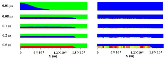
Figure 7.
Flattening and solidification with crystallization process of refinement droplet at 518 m/s. (the green representing gas, the blue liquid, the red solid, respectively, and the different colors indicating different orientations of column grains).
Figure 8 depicts the effect of solidification rate on the crystallization texture of columnar grains. The top and bottom boundaries were subjected to fixed temperatures, while other boundaries were adiabatic. The substrate temperature was kept as 1800 K, 2000 K and 2100 K (see Figure 8a–c). A group of nuclei with a uniform radius of were non-equidistantly seeded at the substrate surface. The solidification rate of the droplet was calculated by this equation of [13]. is the thermal conductivity, the liquid temperature (i.e., the surface temperature of in-flight droplet), the substrate temperature. After calculation, the solidification rates of supersonic droplet were approximately 2.3 × 10⁹, 2.1 × 10⁹ and 2.0 × 10⁹ K/s, respectively. The larger solidification rate as shown in Figure 8a caused a relatively flat and stable solidification front. When the solidification rate decreased, a typical tip splitting occurred in each grain, leading to the so-called seaweed morphology as shown in Figure 8b. When the solidification rate further reduced, the dominating crystallographic texture changed into a dendritic shape (see Figure 8c). This was attributed to the competition between the thermodynamic driving force and surface tension anisotropy, the solidified structure was evolved from a planar shape into a dendritic one. For the columnar grains at a lower solidification rate, it was firstly oriented attachment of grains, and then the migration and junction of grains boundaries under the heat flow direction. The lower heat-activated energy could promote the increase of freedom degree of grains rotation. These small-sized grains were inclined to be assimilated by the larger ones through interfacial atom reconfigurations.

Figure 8.
Competitive growth of columnar grains at different solidification rates: the temperature of bottom surface is (a) 1800 K, (b) 2000 K, (c) 2100 K.
When the substrate temperature sharply decreased to 423 K, the simulation results of columnar grains at an extremely rapid solidification rate (5.4 × 10⁹ K/s) are shown in Figure 9. It can be seen from Figure 9a,b that the average height and width of columnar grains were 0.6 and 0.2 μm, respectively. In order to verify the size of columnar grains, the computational domain of grain growth was a rectangle of μm and the initial temperature was linearly distributed along the direction of the Y-axis. When the solidification time was initially 0.01 μs, these grain shapes implied that heterogeneously nucleated grains formed at the bottom of splat and covered the substrate surface. At μs, these grains grew directionally to the surface of the splat to form a columnar structure. When the flattened droplet was completely solidified ( μs), the average height and width of columnar grains were 0.6 μm and 0.3 μm, respectively. The corresponding crystallographic orientation angle was ranging from 0 to , which was basically in accordance with the above results.

Figure 9.
(a) Columnar grains morphology of YSZ splat at extremely rapid solidification rate; (b) High-magnification image; (c) Growth behavior and temperature distribution of columnar grains.
3.4. Flattening, Solidification and Crystallization Behavior of Two Refined Droplets
When the second droplet impinged on the solidified splat surface after an extremely short time, the splat/splat interface formed. The droplet revealed a time-/space-independent feature [43]. In order to further study the thermodynamics essence of two droplets, a phase model of flattening and solidification process of two droplets is built and is shown in Figure 10. The mesh size is 751 × 351, corresponding to a physical domain of 30 μm × 14 μm. The spreading of the second YSZ droplet on the solidified YSZ splat was similar to the above process of a single droplet. However, the top surface of the solidified splat was curved at 0.4 μs, which caused the uprising jet at 0.5 μs. Moreover, the fattening ratio of the second droplet was relatively smaller than that of the first one. This was attributed to the reduced thermal diffusion at the YSZ splat/splat interface than that of the YSZ splat/stainless steel interface. Moreover, due to the same order parameter c of the Cahn–Hilliard model, a coalescence phenomenon was found at the flattened droplet/splat interface. After 0.5 μs, the surface tension would pull back of the flattened droplet and reduce the surface area. Finally, the splat structure was evolved into a stabilization shape after 0.8 μs.
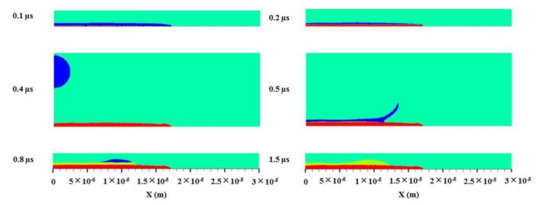
Figure 10.
Flattening and solidification process of two refinement droplets at 518 m/s. (the green representing gas, the blue liquid and the red solid, respectively).
Figure 11 shows the growth behavior of columnar grains within the splat. The corresponding temperature is given in Figure 12. It was clear that the nucleation dynamics between YSZ droplet impacting on a stainless steel substrate or a YSZ splat are obviously different. In the former, copious heterogeneous nucleation was produced at an extremely rapid solidification rate (5.4 × 10⁹ K/s). However, the irregularity of columnar grains surface in solidified YSZ splat for the latter was served as excellent nucleation catalysts, heterogeneous nucleation seemed much earlier. Due to the heat transferred into the cool splat, the temperature of the first splat dropped under 2500 K when the second droplet impacted on the first one, which could be demonstrated by the lowering of the isothermal line of 2500 K at 0.5 μs (see Figure 12). Furthermore, all of the nuclei could completely coherent with the underlying grains since the solidifying materials had the same composition and the lattice parameters [6,12,43,44]. Such epitaxial growth was further observed in Figure 11a.
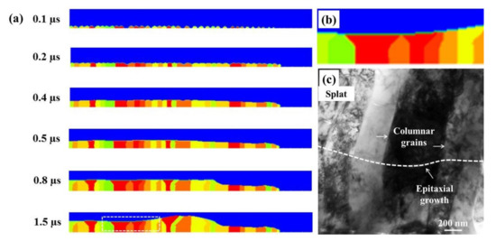
Figure 11.
(a) Growth behavior of columnar grains of two refinement droplets after impacting on a substrate at 518 m/s; (b) Simulation results of columnar grains; (c) Bright Field (BF) cross-sectional TEM images of columnar grains.
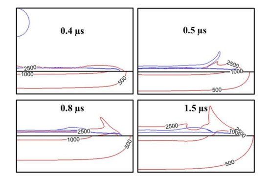
Figure 12.
Temperature distribution of sequential refinement droplets after impacting on a substrate at 518 m/s. (The red represents the isothermal line and the blue YSZ droplet).
Subsequently, the anisotropy played an important role under the thermal driving force, which was demonstrated by the sharp competition of grains at 0.8 μs. For the temperature distribution in Figure 12, it declined rapidly due to around the edge of the bottom splat. At 0.8 μs, the spreading of the second droplet terminated. The heat transfer was dominated by thermal conduction. In particular, as seen from Figure 11b, the fluid flow was obviously affected by the growth direction of grains at 1.5 μs. These columnar grains are skewed with the lateral flow of the droplet spreading. The lateral flow caused the grain boundary curve in one direction due to surface tension in the opposite direction. The temperature of the second splat reduced below 2500 K and the number of protrusion continuously decreased due to the accumulation of flattened droplets.
The TEM image of columnar grains as seen from Figure 11c further suggested the growth mode of columnar grains. The average height and width of columnar grains were (0.5 ± 0.1) μm and (0.3 ± 0.1) μm, respectively. The growth of columnar grains was highly dependent on the solidification rate of the flattened droplet. Our previous study showed that the solidification rate of the supersonic droplet was approximately K/s [13,14]. The preferential growth orientation was in the [101] direction and the corresponding was considered as π/4, which belonged to a regular crystallographic orientation angle. At this extremely rapid solidification rate, the average size of equiaxed/columnar grains decreased to a submicron or nano-level [34,35,45]. The severe non-equilibrium effect promoted the heterogeneous nucleation, leading to an increase in the nucleation number. Subsequently, the nucleus of crystallization grew along the horizontal direction until the incipient crystalline layer was absolutely covered on the substrate surface. Then, competitive growth occurred in the incipient crystalline layer. Ultimately, the crystallization texture was columnar grains with preferential orientation in the negative direction of the heat transfer.
4. Conclusions
In this study, based on the refinement droplets in the supersonic plasma jet, experimental and numerical modeling for flattening and rapid solidification with crystallization behavior of supersonic YSZ droplets were studied. The main conclusions are as follows:
- (1)
- The content of refined droplets was about 90%. Simultaneous improvement of temperature and velocity of in-flight droplets was beneficial to the refinement of droplets, which was highly dependent on the critical threshold between the hydrodynamic pressure and added pressure caused by the surface tension force.
- (2)
- An optimized numerical model was established in order to accurately reproduce the multi-physical coupling process of supersonic impingement of single or two refined droplets, which was based on the Navier–Stokes, energy balance, the Cahn–Hilliard, heat transfer, phase-field and orientational field equations.
- (3)
- With the increase of solidification rate (2.0 × 10⁹ K/s~5.4 × 109 K/s), the crystallographic texture on the flattened droplets surface consisted of submicron/nano equiaxed grains. The cross-sectional solidified structure of a single flattened droplet was evolved from a dendritic shape into a columnar one. The height and width of columnar grains were basically in accordance with experimental results. For two flattened droplets, their interface exhibited an epitaxial growth of columnar grains.
- (4)
- This optimized model can be an effective method in predicting flattening and solidification with crystallization behavior of droplets during plasma spraying. The obtained results will expect to provide the theoretical and experimental support for high-performance coatings. Further research should be focused on the pileup and crystallization process of multiple supersonic-droplets in the perpendicular and horizontal directions after impacting a substrate.
Author Contributions
Conceptualization, Y.B. and K.W.; methodology, J.Z.; software, M.S.; validation, Q.L., Y.S., and Y.H.; formal analysis, N.C., Q.L., and Y.S; investigation, X.D. and Z.S.; resources, M.S., X.D., and Z.S.; data curation, N.C.; writing—original draft preparation, Y.W.; writing—review and editing, Y.W. and Y.B.; visualization, N.C. and M.S.; supervision, K.W. and Y.M.; project administration, K.W. and J.Z.; funding acquisition, Y.W. and Y.B. All authors have read and agreed to the published version of the manuscript.
Funding
This work was supported by National Natural Science Foundation of China (Grant No. 52005388), National Key R&D Program of China (Grant No. 2018YFB2004002), China Postdoctoral Science Foundation (Grant No. 2019M653598) and Natural Science Foundation of Shaanxi Province (Grant No. 2019TD-020 and No. 2019JQ-586).
Conflicts of Interest
The authors declare no conflict of interest.
References
- Shu, Y.; Ai, X.; Li, B.Q. Phase-field modelling of solidification microstructure formation using the discontinuous finite element method. Int. J. Numer. Meth. Eng. 2007, 69, 1194. [Google Scholar] [CrossRef]
- Zhang, Y.; Matthews, S.; Hyland, M. Role of solidification in the formation of plasma sprayed nickel splats through simulation and experimental observation. Int. J. Heat Mass Tran. 2017, 115, 488. [Google Scholar] [CrossRef]
- Liu, H.; Jazi, H.R.S.; Bussmann, M. Experiments and modeling of rapid solidification of plasma-sprayed yttria-stabilized zirconia. Acta Mater. 2009, 57, 6013. [Google Scholar] [CrossRef]
- Zhang, J.B.; Wang, H.F.; Kuang, W.W. Rapid solidification of non-stoichiometric intermetallic compounds: Modeling and experimental verification. Acta Mater. 2018, 148, 86. [Google Scholar] [CrossRef]
- Chraska, T.; King, A.H. Transmission electron microscopy study of rapid solidification of plasma sprayed zirconia-Part I. first splat solidification. Thin Solid Film. 2001, 397, 30. [Google Scholar] [CrossRef]
- Chraska, T.; King, A.H. Transmission electron microscopy study of rapid solidification of plasma sprayed zirconia-part II. Interfaces and subsequent splat solidification. Thin Solid Film. 2001, 397, 40. [Google Scholar] [CrossRef]
- Li, C.J.; Yang, G.J.; Li, C.X. Development of particles interface bonding in thermal spray coatings: A review. J. Therm. Spray Technol. 2012, 22, 192. [Google Scholar] [CrossRef]
- Zhang, Z.H.; Luo, J.X.; Li, Q. Mechanism of competitive grain growth in 8YSZ splats deposited by plasma spraying. J. Therm. Spray Technol. 2015, 24, 885. [Google Scholar] [CrossRef]
- Shinoda, K.; Demura, M.; Murakami, H. Characterization of crystallographic texture in plasma-sprayed splats by electron-backscattered diffraction. Surf. Coat. Technol. 2010, 204, 3614. [Google Scholar] [CrossRef]
- Zhang, J.B.; Wang, H.F.; Zhang, F. Growth kinetics and grain refinement mechanisms in an undercooled melt of a CoSi intermetallic compound. J. Alloy. Compd. 2019, 781, 13. [Google Scholar] [CrossRef]
- Wei, X.X.; Lin, X.; Xu, W. Remelting-induced anomalous eutectic formation during solidification of deeply undercooled eutectic alloy melts. Acta Mater. 2015, 95, 44. [Google Scholar] [CrossRef]
- Yao, S.W.; Liu, T.; Li, C.J. Epitaxial growth during the rapid solidification of plasma-sprayed molten TiO2 splat. Acta Mater. 2017, 134, 66. [Google Scholar] [CrossRef]
- Wang, Y.; Bai, Y.; Yang, Q.Z. A transmission electron microscopy study of the microstructure and interface of zirconia-based thermal barrier coatings. J. Alloy. Compd. 2015, 619, 820. [Google Scholar] [CrossRef]
- Wang, Y.; Bai, Y.; Wu, K. Flattening and solidification behavior of in-flight droplets in plasma spraying and micro/macro-bonding mechanisms. J. Alloy. Compd. 2019, 784, 834. [Google Scholar] [CrossRef]
- Bai, Y.; Han, Z.H.; Li, H.Q. Structure–property differences between supersonic and conventional atmospheric plasma sprayed zirconia thermal barrier coatings. Surf. Coat. Technol. 2011, 205, 3833. [Google Scholar] [CrossRef]
- Bai, Y.; Zhao, L.; Liu, K. Fine-lamellar structured thermal barrier coatings fabricated by high efficiency supersonic atmospheric plasma spraying. Vacuum 2014, 99, 119. [Google Scholar] [CrossRef]
- Tang, J.J.; Bai, Y.; Zhang, J.C. Microstructural design and oxidation resistance of CoNiCrAlY alloy coatings in thermal barrier coating system. J. Alloy. Compd. 2016, 688, 729. [Google Scholar] [CrossRef]
- Cheng, F.; Lian, L.Y.; Li, L.Y. Hybrid growth modes of PbSe nanocrystals with oriented attachment and grain boundary migration. Adv. Sci. 2019, 6, 1802202. [Google Scholar] [CrossRef]
- Provatas, N.; Dantzig, J.A.; Athreya, B. Using the phase-field crystal method in the multi-scale modeling of microstructure evolution. JOM 2007, 59, 83. [Google Scholar] [CrossRef]
- Kobayashi, R. Modeling and numerical simulations of dendritic crystal growth. Phys. D 1993, 63, 410. [Google Scholar] [CrossRef]
- Caginalp, G.; Xie, W. Phase-field and sharp-interface alloy models. Phys. Rev. E 1993, 48, 1897. [Google Scholar] [CrossRef] [PubMed]
- Steinbach, I.; Apel, M. Phase-field simulation of rapid crystallization of silicon on substrate. Mater. Sci. Eng. A 2007, 449–451, 95. [Google Scholar] [CrossRef]
- Warren, J.A.; Kobayashi, R.; Lobkovsky, A.E. Extending phase field models of solidification to polycrystalline materials. Acta Mater. 2003, 51, 6035. [Google Scholar] [CrossRef]
- Bruna, P.; Pineda, E.; Rojas, J.I. Phase-field modeling of microstructural evolution in primary crystallization. J. Alloy. Compd. 2009, 483, 645. [Google Scholar] [CrossRef]
- Al, X.; Shu, Y.; Li, B.Q. Discontinuous finite-element phase-field modeling of polycrystalline grain growth with convection. Comput. Math. Appl. 2006, 52, 721. [Google Scholar]
- Yamaguchi, M.; Beckermann, C. Simulation of solid deformation during solidification: Shearing and compression of polycrystalline structures. Acta Mater. 2013, 61, 2268. [Google Scholar] [CrossRef]
- Cahn, J.W.; Hilliard, J.E. Free energy of a nonuniform system I: Interfacial free energy. J. Chem. Phys. 1958, 28, 258. [Google Scholar] [CrossRef]
- Jacqmin, D. Calculation of two-phase Navier-Stokes flows using phase-field modeling. J. Comput. Phys. 1999, 155, 96. [Google Scholar] [CrossRef]
- Fard, M.P.; Pershin, V.; Chandra, S. Splat shapes in a thermal spray coating process: Simulations and experiments. J. Therm. Spray Technol. 2002, 11, 206. [Google Scholar] [CrossRef]
- Wei, P.; Wei, Z.; Li, S. Splat formation during plasma spraying for 8 mol % yttria-stabilized zirconia droplets impacting on stainless steel substrate. App. Surf. Sci. 2014, 321, 538. [Google Scholar] [CrossRef]
- Shen, M.G.; Li, B.Q.; Yang, Q.Z. A modified phase-field Three-dimensional model for droplet impact with solidification. Int. J. Multiph. Flow 2019, 116, 51. [Google Scholar] [CrossRef]
- Shen, M.G.; Li, B.Q.; Bai, Y. Numerical modeling of YSZ droplet impact/spreading with solidification microstructure formation in plasma spraying. Int. J. Heat. Mass Tran. 2020, 150, 119267. [Google Scholar] [CrossRef]
- Shen, M.G.; Li, B.Q.; Bai, Y. Numerical investigation of solidification microstructure formation in sequential YSZ droplet impact under supersonic plasma spraying. Int. J. Heat. Mass Tran. 2020, 157, 119844. [Google Scholar] [CrossRef]
- Bai, Y.; Zhao, L.; Wang, Y. Fragmentation of in-flight particles and its influence on the microstructure and mechanical property of YSZ coating deposited by supersonic atmospheric plasma spraying. J. Alloy. Compd. 2015, 632, 794. [Google Scholar] [CrossRef]
- Wang, Y.; Bai, Y.; Liu, L. Microstructural evolution of plasma sprayed submicron-/nano-zirconia-based thermal barrier coatings. Appl. Surf. Sci. 2016, 363, 101. [Google Scholar] [CrossRef]
- Wang, Y.; Bai, Y.; Yuan, T. Failure analysis of fine-lamellar structured YSZ based thermal barrier coatings with submicro/nano-grains. Surf. Coat. Technol. 2017, 319, 95. [Google Scholar] [CrossRef]
- Duan, R.Q.; Koshizuka, S.; Yoshiaki, O. Two-dimensional simulation of drop deformation and breakup at around the critical Weber number. Nucl. Eng. Des. 2003, 225, 37. [Google Scholar] [CrossRef]
- Chyou, Y.P.; Pfender, E. Behavior of particulates in thermal plasma flows. Plasma Chem. Plasma Proc. 1989, 9, 45. [Google Scholar] [CrossRef]
- White, F.M. Viscous Fluid Flow, 2nd ed.; McGraw-Hill: New York, NY, USA, 1974. [Google Scholar]
- Kentaro, S. Influence of impact parameters of zirconia droplets on splat formation and morphology in plasma spraying. J. Appl. Phys. 2006, 100, 074903. [Google Scholar]
- Josserand, C.; Thoroddsen, S.T. Drop impact on a solid surface. Annu. Rev. Fluid Mech. 2016, 48, 365. [Google Scholar] [CrossRef]
- Ren, J.K.; Chen, Y.; Xu, B. A vector-valued phase field model for polycrystalline solidification using operator splitting method. Comp. Mater. Sci. 2019, 163, 37. [Google Scholar] [CrossRef]
- Yang, E.J.; Luo, X.T.; Yang, G.J. Epitaxial grain growth during 8YSZ splat formation on polycrystalline YSZ substrates by plasma spraying. Surf. Coat. Technol. 2015, 274, 37. [Google Scholar] [CrossRef]
- Yao, S.W.; Li, C.J.; Tian, J.J. Conditions and mechanisms for the bonding of a molten ceramic droplet to a substrate after high-speed impact. Acta Mater. 2016, 119, 9. [Google Scholar] [CrossRef]
- Wang, Y.; Bai, Y.; Wu, K. Time-/space-sensitive sintering kinetics of plasma sprayed multi-modal nanostructured coating. Surf. Coat. Technol. 2020, 381, 125115. [Google Scholar] [CrossRef]
Publisher’s Note: MDPI stays neutral with regard to jurisdictional claims in published maps and institutional affiliations. |
© 2020 by the authors. Licensee MDPI, Basel, Switzerland. This article is an open access article distributed under the terms and conditions of the Creative Commons Attribution (CC BY) license (http://creativecommons.org/licenses/by/4.0/).