Article

Encapsulation of Few-Layer MoS2 in the Pores of Mesoporous Carbon Hollow Spheres for Lithium-Sulfur Batteries

College of Materials Science and Engineering, Qingdao University of Science and Technology, Qingdao 266042, China
*
Author to whom correspondence should be addressed.
Nanomaterials 2019, 9(9), 1247; https://doi.org/10.3390/nano9091247
Submission received: 19 July 2019 / Revised: 19 August 2019 / Accepted: 26 August 2019 / Published: 3 September 2019

Abstract

:
Integrating a highly conductive carbon host and polar inorganic compounds has been widely reported to improve the electrochemical performances for promising low-cost lithium sulfur batteries. Herein, a MoS2/mesoporous carbon hollow sphere (MoS2/MCHS) structure has been proposed as an efficient sulfur cathode via a simple wet impregnation method and gas phase vulcanization method. Multi-fold structural merits have been demonstrated for the MoS2/MCHS structures. On one hand, the mesoporous carbon hollow sphere (MCHS) matrix, with abundant pore structures and high specific surface areas, could load a large amount of sulfur, improve the electronical conductivity of sulfur electrodes, and suppress the volume changes during the repeated sulfur conversion processes. On the other hand, ultrathin multi-layer MoS2 nanosheets are revealed to be uniformly distributed in the mesoporous carbon hollow spheres, enhancing the physical adsorption and chemical entrapment functionalities towards the soluble polysulfide species. Having benefited from these structural advantages, the sulfur-impregnated MoS2/MCHS cathode presents remarkably improved electrochemical performances in terms of lower voltage polarization, higher reversible capacity (1094.3 mAh g−1), higher rate capability (590.2 mAh g−1 at 2 C), and better cycling stability (556 mAh g−1 after 400 cycles at 2 C) compared to the sulfur-impregnated MCHS cathode. This work offers a novel delicate design strategy for functional materials to achieve high performance lithium sulfur batteries.

Graphical Abstract

1. Introduction

The development of lithium ion (Li-ion) battery technologies cannot meet the ever-growing demand of electric vehicles and automobiles due to their relatively low energy density (387 Wh kg−1 for LiCoO2/C) and their relatively high cost. Fortunately, lithium–sulfur (Li-S) batteries have an ultrahigh theoretical energy density (2600 Wh kg−1) and high theoretical specific capacity of 1675 mA h g−1 based on the multielectron conversion electrochemistry between lithium and elemental sulfur [1,2]. In addition, elemental sulfur, the main cathode material of Li–S batteries, is eco-friendly and low-cost [3]. Considering those factors, Li-S batteries are considered as next-generation high-energy batteries [4,5,6]. However, several intrinsic problems from sulfur cathodes are impeding the commercial application of lithium-sulfur battery technologies. Firstly, the intrinsic electronic insulating nature of the charged-state elemental S8 and discharge product (Li2S2 and Li2S) leads to slow kinetics, low rate capability, and serious electrochemical polarizations. Secondly, dramatic volume expansion (about 80%) during the conversion reaction from S to Li2S brings about pulverization of the electrodes and short electrode service lifetime [7,8]. Last but not least, the intermediated products of lithium polysulfides (Li2Sn, 4 ≤ n ≤ 8) can migrate to the lithium metal anode as its solubility in the organic liquid electrolyte, leading to serious loss of active material, low coulombic efficiency, and poor cycling stability [9,10,11].
To address the aforementioned issues, significant efforts have been made in designing cathodes, such as preparing all kinds of carbon–sulfur composites, conductive polymers-sulfur composites, metal organic framework (MOF)–sulfur composites, and so on [12,13,14,15,16,17,18,19]. Conductive carbon has been one of the most appropriate hosts for sulfur to date [20]. Nanostructured carbon materials may load a large amount of sulfur and relieve the volume expansion of sulfur on account of their large specific surface area, great pore volume, and controllable pore size distribution. However, the “shuttle effect” of polysulfides cannot be solved in carbon-sulfur material due to poor affinity between nonpolar carbon and polar polysulfides [21,22,23]. Recently, some polar materials, such as metal oxides, transition metal disulfides, polymer materials, and polar heteroatoms, have been paid much attention because of the strong chemical interactions with soluble lithium polysulfides [24,25,26,27,28,29,30]. Especially, polar molybdenum disulfide (MoS2) has advantages of high safety, low cost, and being a simple synthetic method [31], Nevertheless, the poor conductivity of these polar materials hinders the polysulfide conversion, resulting in electrochemical performance degradation. Hence, the combined use of conductive carbon materials and polar materials is usually accepted in establishing sulfur electrode hosts [32,33,34]. However, the electron transport pathway still can be blocked sometimes because of the phase segregation caused by the lack of surface affinity between carbon materials and polar materials [35]. Therefore, it is very meaningful to design sulfur electrode hosts with hassle-free cladding for polar nanometer materials.
In this study, a delicately-designed hierarchical MoS2/mesoporous carbon hollow sphere (MoS2/MCHS) structure is developed by a simple wet impregnation method and gas phase vulcanization method as a sulfur host material for Li-S batteries. The encapsulation of MoS2 in the pores of mesoporous carbon hollow spheres (MCHS) possesses multi-fold structural merits of both the chemical entrapment of MoS2 and high conductivity of MCHS. Specifically, on the path that polysulfides must cross, special MoS2 defense lines are built. Polar MoS2 can chemically trap polysulfides via strong chemical bonds, so that polysulfides are largely fixed and remained inside the conductive MCHS (Scheme 1). Additionally, the conductive network provides electrons for redox reaction in a timely manner to facilitate polysulfide conversion kinetics. The unique structure not only provides adequate storage space to sulfur, but also increases sulfur utilization. Therefore, the MoS2/MCHS/S electrode shows improved cycling stability and better rate capability in comparison to the MCHS/S electrode. The as-proposed unique MoS2/MCHS host structure provides a new method for designing high performance functional electrode materials for energy application.

2. Materials and Methods

2.1. Preparation of MoS2/MCHS Composite

All of the chemicals were used as received. Mesoporous carbon hollow spheres used in this work were prepared by the surfactant-free method using tetrapropyl orthosilicate, resorcinol, and formaldehyde [36]. The MoS2/MCHS composite was synthesized using a simple wet impregnation method and gas phase vulcanization method. Typically, phosphomolybdic acid hydrate (34 mg) was dissolved in 5 mL of ethanol under vigorous stirring for 30 min. Then, 0.1 g of MCHS powder treated with nitric acid was dispersed in the above aqueous solution by ultrasonic method for 30 min, and dried under vacuum at 60 °C for 12 h. Finally, the sample and sulfur powder in a 1:2 mass ratio were heated under Ar atmosphere at 600 °C for 2 h with a heating rate of 5 °C/min to obtain MoS2/MCHS composite.

2.2. Preparation of the MoS2/MCHS/S and MCHS/S Composites

The MoS2/MCHS/S and MCHS/S composites were synthesized through a classic melt-diffusion strategy. Briefly, sulfur powder and MoS2/MCHS (or MCHS) in a 3:1 mass ratio were mixed uniformly in a mortar. The mixture was heated at 155 °C for 12 h in a 50 mL Teflon-lined stainless-steel autoclave. After that, the mixture was heated at 200 °C for 1 h with a heating rate of 10 °C/min in a quartz tube filled with N2 to distribute the sulfur uniformly in MoS2/MCHS composite (or MCHS).

2.3. Material Characterizations

The morphology of the samples was analyzed by performing field-emission scanning electron microscopy (SEM; JSM-6700F, JEOL Ltd., Tokyo, Japan), transmission electron microscopy (TEM; JEM-2100F, JEOL Ltd., Tokyo, Japan), and high-resolution transmission electron microscopy (HRTEM; Tecnai G20, FEI corp., Hillsboro, OR, USA). Thermogravimetric analysis (TGA) was performed on a TG-DTA 6200 LAB SYS analyzer (SII NanoTechnology Inc., Tokyo, Japan) under N2 and air atmosphere. The pore-size distribution was obtained by nitrogen adsorption–desorption measurement on a micromeritics ASAP 2020 analyzer (Micromeritics Instrument corp., Atlanta, GA, USA) at 77 K. The composition of the samples was determined by X-ray diffraction (XRD; D-max-gA, Rigaku corp., Tokyo, Japan) with Cu Kα radiation from 5° to 80° (2θ). X-ray photoelectron spectroscopy (XPS) was performed using a PHI 550 spectrometer (Perkin-Elmer corp., Waltham, MA, USA) with Al Kα radiation.

2.4. Electrochemical Measurements

The electrochemical tests were conducted on standard CR2032-type coin cells assembled in an argon filled glove box. The cathode was fabricated by mixing 70 wt.% MoS2/MCHS/S (or MCHS/S), with 20 wt.% carbon black (Super-P) and 10 wt.% poly(vinyl difluoride) (PVDF) in 1-methyl-2-pyrrolidinone (NMP), and the mixture was cast onto a pure Al foil. The mass loading of active materials on Al foil was about 0.5 mg cm−2. The electrochemical performances of electrodes with a high mass loading of about 1.6 mg cm−2 were also investigated. Besides, a lithium metal foil was served as the counter electrode and separated by a Celgard 2500 membrane separator. The electrolyte was a solution of 1.0 M bis(trifluoromethane)sulfonimide lithium salt and 0.1 M lithium nitrate in dimethyl ether (DME)/dioxolane (DOL) (volume ratio: 1:1). The galvanostatic discharge-charge experiments were carried out using a CT2001A battery tester (Land Electronic Co., Ltd., Wuhan, China) over a voltage range of 1.5 V–3.0 V (vs. Li/Li+). Cyclic voltammetry (CV) tests were conducted on an Autolab PGSTAT302N electrochemical workstation at a scan rate of 0.1 mV s−1.

3. Results and Discussion

3.1. Structure and Morphology

The crystalline structure of both the MoS2/MCHS and MCHS structures was evaluated with XRD (Figure 1a). The broad diffraction at around 2θ = 20–30° corresponds to amorphous carbon characteristic peaks of MCHS. Three typical diffraction peaks at 33°, 39°, and 58° can be attributed to the (100), (103), and (110) plans of the MoS2 phase (JCPDS 37–1492), respectively [37]. An invisible peak of the (002) plane (2θ = 14°) suggests the presence of “graphene-like” layers that are less than five layers. This result agrees with the results of HRTEM [38]. To determine the content of MoS2 in the MoS2/MCHS structures, a TGA test was performed from room temperature to 800 °C in air (Figure 1b). The MoO3 residue after TGA comes from the oxidation of MoS2, so the proportion of MoS2 in the MoS2/MCHS structures was approximately 17.5%.
The morphologies of the MoS2/MCHS and MCHS structures were observed with SEM and TEM images. The MCHS structures were prepared by one-pot, surfactant-free polymerization method, which exhibits a rough-surfaced spherical structure with an average diameter of 320 nm (Figure S1). As shown in Figure 2a, the shape and size of the MoS2/MCHS structures are similar to those of the MCHS structures. Compared with the MCHS structures, the surface roughness of the MoS2/MCHS structures decreases, which may be caused by the reduced pore diameter under the sulfidation process. Besides, there is no obvious layered structure of MoS2 on the surface of the MCHS structures. To clarify the distribution of MoS2 in carbon shell, EDS element mapping is exhibited in Figure 2c. As can be seen, the C, Mo, and S elements are evenly distributed in the sphere. TEM images in Figure 2d and Figure S2a,b reveal that both the MoS2/MCHS and MCHS structures have similar radial porous shells, the thickness of which is about 50 nm. The radial pore channels and hollow morphology of both the MoS2/MCHS and MCHS structures are convenient for sulfur impregnation. Additionally, such a structure can also buffer volume changes of sulfur and shorten the ion or electron diffusion distance during the charge-discharge process. The HRTEM images were investigated to prove the existence of MoS2. Unlike the HRTEM images of MCHS (Figure S2c,d), there are some ultrathin MoS2 multi-layer crystals uniformly distributed in the MoS2/MCHS structures (Figure 2e,f). Figure 2f reveals the shell of MoS2/MCHS possesses abundant mesopores. Figure 2f indicates that the interplanar spacing of crystallites is 0.62 nm, which corresponds to the lattice spacing of MoS2 (002) plane [39]. Layered MoS2 is successfully encapsulated in the pores of the MCHS structures, evidenced in the HRTEM images. Additionally, layered MoS2 completely surrounded by conductive carbon may facilitate polysulfide conversion kinetics, and thus increase sulfur utilization.
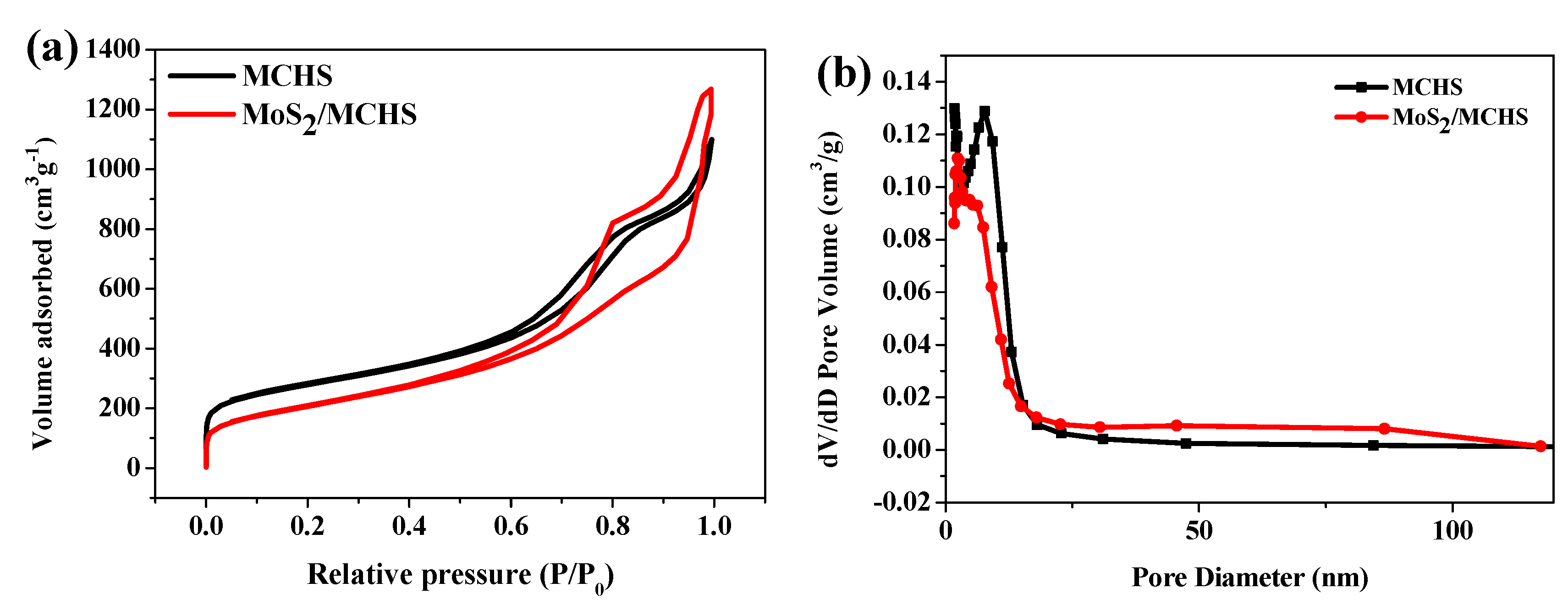
To investigate the pore structures after introducing MoS2, nitrogen adsorption-desorption isotherms measurements were conducted. Figure 3a presents two similar N2 adsorption-desorption isotherms, which show mixed features of type-II isotherm and type-IV isotherm. Type-IV isotherm is characterized by the presence of significant hysteresis loops. Type-II isotherm represents the macropores material, while Type-IV isotherm represents the mesoporous structure. The pore size distribution plots were obtained by the Barrett-Joyner-Halenda (BJH) method (Figure 3b). The surface area and pore volume of the materials are listed in Table S1. After the introduction of MoS2, the main peak of the distribution plots shifts 6 nm towards a smaller pore-size (2 nm), indicating that the encapsulation of MoS2 in the pores of the MCHS structures leads to reduced pore diameter. In addition, the surface area of the MoS2/MCHS structure (727.32 m2 g−1) is slightly smaller than that of the MCHS structure (941.62 m2 g−1), suggesting a slight change of specific surface area produced by the addition of MoS2. Fortunately, the MoS2/MCHS structures basically maintain a large specific surface area and a high pore volume, which is beneficial to the infiltration of elemental sulfur and the transport of lithium ions. The pore structures before and after sulfur impregnation are compared in Figure S3 to determine the distribution of sulfur. The pore volume becomes smaller at any pore diameter after sulfur impregnation, due to the S distribution across the entire sphere.
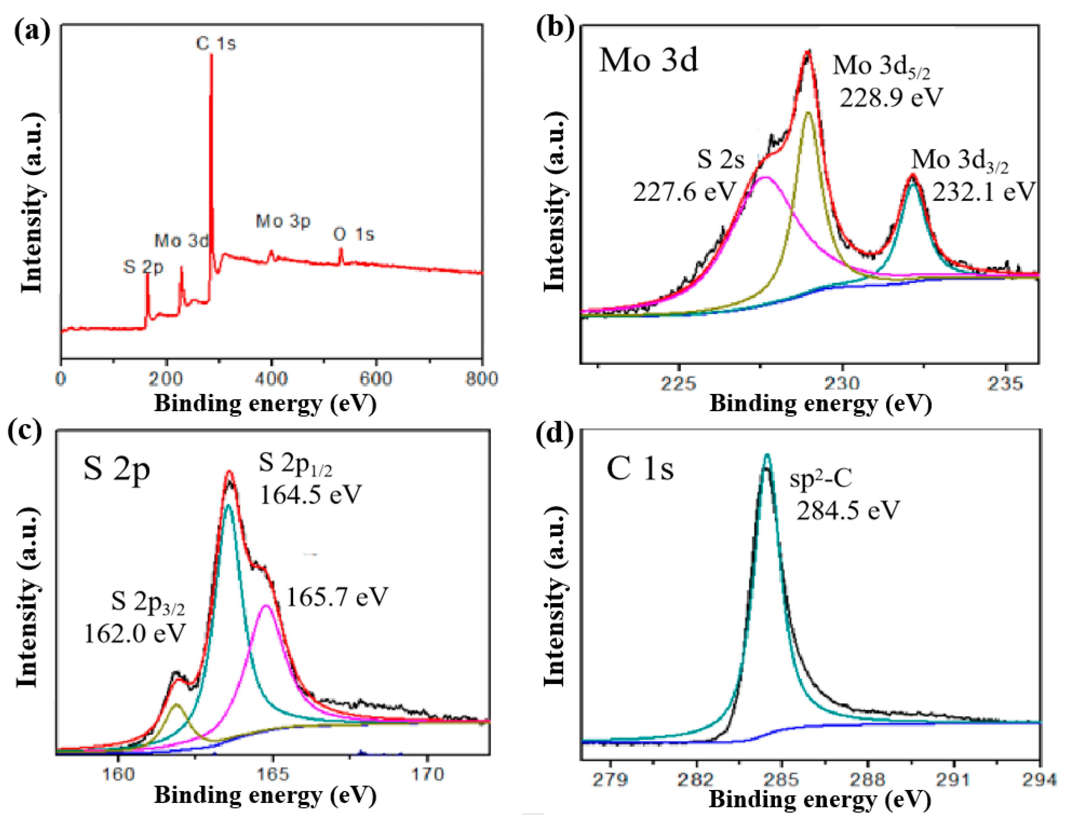
The chemical composition of the MoS2/MCHS structures was investigated by XPS measurements. The XPS spectrum in Figure 4a clearly indicates that the MoS2/MCHS structures are composed of the Mo, S, C, and O elements, suggesting the existence of oxygen function groups on the surface of the material. The binding energies of Mo 3d5/2 and Mo 3d3/2 are located at 228.9 and 232.1 eV, demonstrating the presence of Mo4+ (Figure 4b) [40]. Additionally, the peak at 227.6 eV could be attributed to the S 2s orbital of MoS2 [41]. In the high-resolution spectrum of S 2p, the peaks at 162 and 164.5 eV are assigned to S 2p3/2 and S 2p1/2, which are associated with the existence of divalent sulfide ions (S2−). The 165.7 eV peaks may result from the presence of the bridging disulfide S22−. As shown in Figure 4d, the peaks at 284.5 eV are due to the C = C bond in the MCHS structures. The results indicate that the MoS2/MCHS structures were successfully prepared in this research.
Figure S4a,b show that the morphology of both the MCHS and MoS2/MCHS structures were not obviously changed after sulfur impregnation. TGA data were also used to analyze the weight content and thermal stability of sulfur in the MoS2/MCHS/S composites, which were obtained between room temperature and 400 °C in N2 atmosphere (Figure S5). Considering that the sublimation of elemental sulfur is the reason for the weight loss, the contents of sulfur in both the MCHS/S and MoS2/MCHS/S composites are 71.5 and 72.6 wt %, respectively. In addition, the better thermal stability and sulfur retention ability of the MoS2/MCHS/S composites are observed due to the higher initial decomposition temperature and lower decomposition rate in early decay. The presence of MoS2 not only does not decrease the storage space of sulfur, but can load more sulfur on account of the stronger absorption.
A simple visual adsorption test was conducted to verify the interactive activity of the MoS2/MCHS structures and the soluble lithium polysulfide (Figure S6). The Li2S6 solution (0.01 M) with reddish brown color in Figure S6c is prepared by dissolving a stoichiometric amount of sulfur and Li2S in a 1:1 (v/v) DOL/DME solvent. The solution color changes from reddish brown to yellow after the addition of the MCHS structures owing to the physical absorptivity towards lithium polysulfides (Figure S6b). In sharp contrast, the solution is almost completely discolored after adding the MoS2/MCHS structures to the lithium polysulfide solution (Figure S6a). This might be responsible for the synergistic effects from the physical adsorption of the mesoporous carbon hollow spheres and the chemical bond between polar MoS2 and polysulfide. The strong interaction between the MoS2/MCHS structures and lithium polysulfide is beneficial for suppressing the “shuttle effect” of polysulfide and the destruction of Li anodes.

3.2. Electrochemical Performance

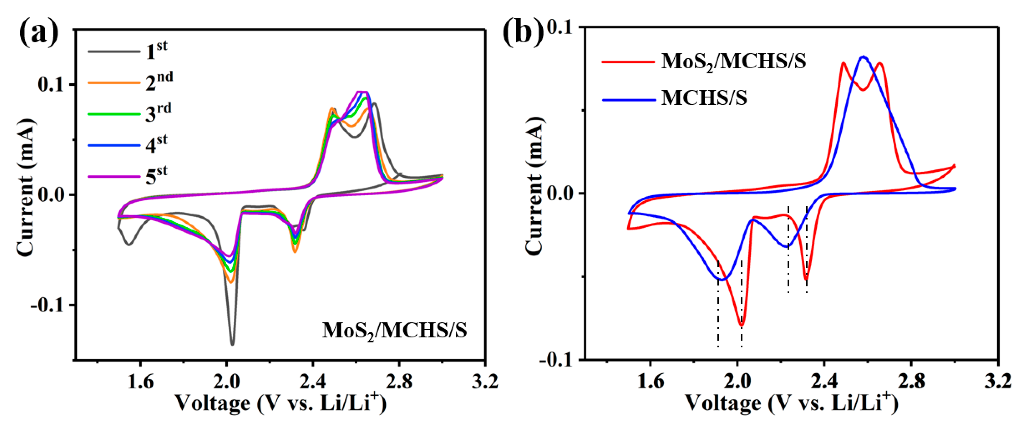
The typical CV curves of both the MoS2/MCHS/S cathodes and MCHS/S cathodes were measured over a voltage range of 1.5–3.0 V at a scan rate of 0.1 mV s−1 (Figure 5a and Figure S7). In Figure 5a, the CV curves of the MoS2/MCHS/S cathode show two representative reduction peaks at 2.03 and 2.32 V, corresponding to the step-wise reduction of S8 to the long-chain polysulfides (Li2Sn, 4 ≤ n ≤ 8) and short-chain polysulfides (Li2S2/Li2S), respectively [41]. The reverse distinguishable oxidation peaks located at 2.49 and 2.68 V are associated with the formation of long-chain polysulfides and elemental sulfur, respectively, suggesting good reaction kinetics. In contrast, two merging oxidation peaks at around 2.52 V are observed in the CV curves of the MCHS/S cathode (Figure S7), indicating the two-step delithiation process. Furthermore, higher peak current and larger CV enclosed area of the MoS2/MCHS/S cathode also indicate the faster electrochemical kinetics (Figure 5b). The potential gap between oxidation and reduction peaks of the MoS2/MCHS/S cathodes (0.46 V) are lower than that of the MCHS/S cathodes (0.73 V), which illustrates a lower cell polarization and faster Li ions diffusion in the MoS2/MCHS/S cathode [42]. The above analyses suggest that the uniform dispersion of MoS2 in the MCHS matrix facilitates the capture of polysulfides and boosts the conversion rates of polysulfides.
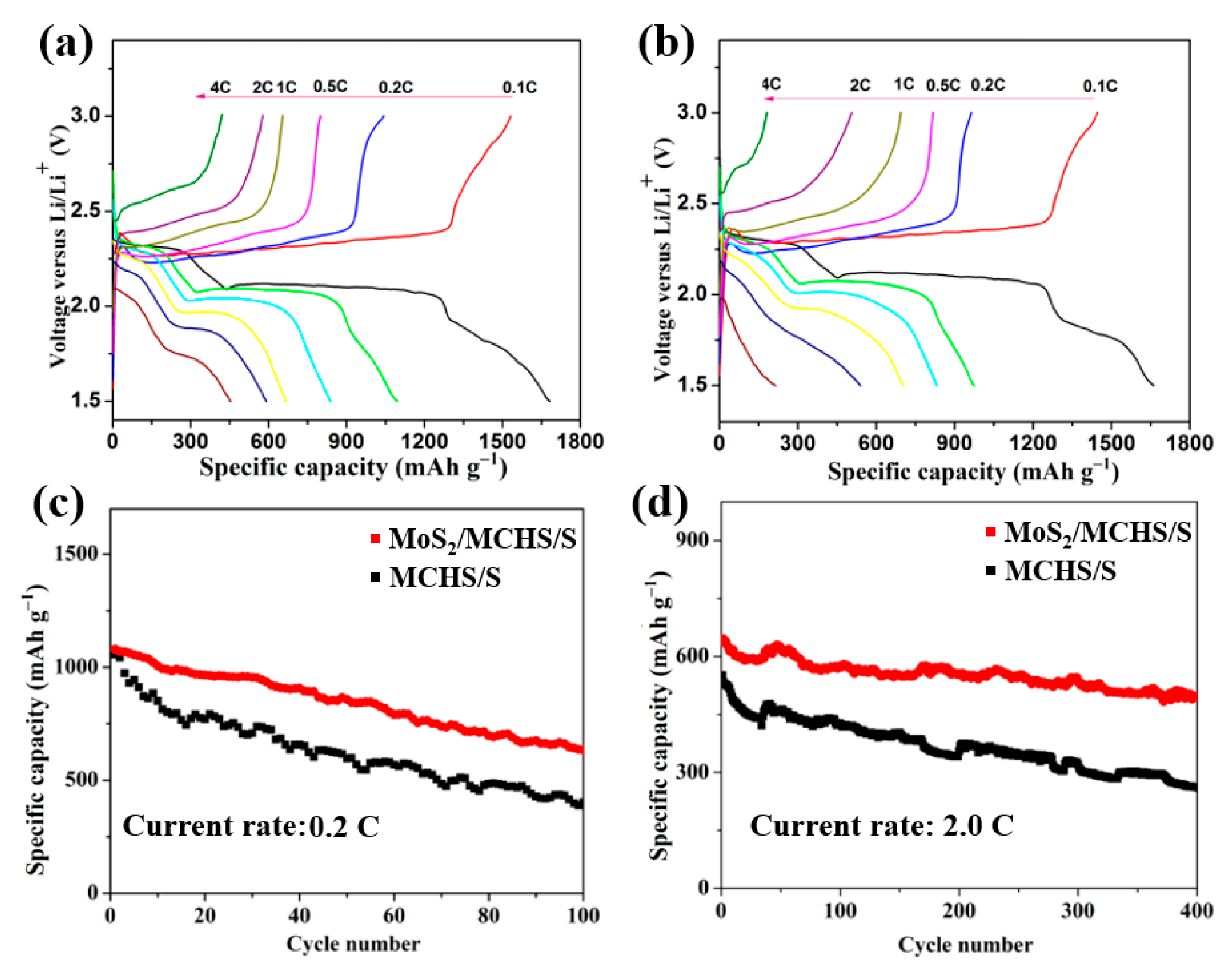
The galvanostatic charge–discharge profiles of both the MoS2/MCHS/S electrode and the MCHS/S electrode at various currents are shown in Figure 6a,b. Two representative discharge plateaus can be observed in the curves of both the MoS2/MCHS/S electrode and MCHS/S electrode. At the current rate of 0.1 C, the upper discharge flat at 2.3 V is related to the transformation from sulfur to long-chain polysulfides, while the lower plateau at 2.1 V versus Li/Li+ is attributed to the formation of short-chain lithium polysulfides [43]. This result is in agreement with the CV analysis. In Figure 6b, the low potential of around 1.8 V corresponds to the conversion from Li2S2 to Li2S [44]. With the increase of the current rate, the voltage of the discharge plateau is more negative and the voltage of the charge flat is more positive, indicating greater polarization. It is noticeable that the polarization of the MoS2/MCHS/S cathode is smaller than that of the MCHS/S cathode, especially at high current rate. The clearly visible voltage platform of the MoS2/MCHS/S composite can be observed even at the 4 C rate, suggesting a fast electrode reaction. Meanwhile, in comparison to the MCHS/S cathode, the MoS2/MCHS/S cathode has a longer plateau due to the strong interaction between soluble polysulfides and MoS2, as well as high utilization percentage of sulfur.
The rate capabilities of both the MoS2/MCHS/S cathode and the MCHS/S cathode are displayed in Figure S8. The discharge capacities of the MoS2/MCHS/S cathodes are 1680.6, 1094.3, 838.6, 667.6, 590.2, and 453.9 mAh g−1 at rates of 0.1, 0.2, 0.5, 1, 2, and 4 C, respectively. When the current rate returns to 0.1 C, the specific capacity of the MoS2/MCHS/S cathode is maintained at a high reversible capacity of 1037.3 mAh g−1, implying a good reversibility. Compared with the MCHS/S electrode, the MoS2/MCHS/S electrode remarkably displays an enhanced specific capacity at high current rates (two times higher at 4 C).
Cycling performances of the MCHS/S and MoS2/MCHS/S cathodes at the 0.2 C rate are compared in Figure 6c. The MCHS/S cathode exhibits a lower initial specific capacity (1056.2 mAh g−1) and a severe capacity fading rate of 59.86% after 100 cycles. One possible reason is that the “shuttle effect” caused by soluble polysulfide occurs in this cathode system. In contrast, the MoS2/MCHS/S cathode shows a higher discharge of 1079.5 mAh g−1 and a reduced capacity decay rate of 37.40%, indicating that MoS2 can indeed trap the dissolved polysulfide and effectively suppress the “shuttle effect”. The electrochemical performance of electrodes with a high mass loading of about 1.6 mg cm−2 was also investigated in Figure S9. The MoS2/MCHS/S cathodes with a relatively high mass loading exhibited comparable specific capacity and cycle performance. Figure S9 compares the cycling performances of the MCHS/S and MoS2/MCHS/S cathodes with a high mass loading at the 1.0 C rate. The MCHS/S cathode shows a capacity fading rate of 27.08% after 100 cycles, while the MoS2/MCHS/S cathode displays an obviously improved capacity fading rate of 5.07% after 100 cycles. The MoS2/MCHS/S cathodes exhibit less capacity decay than the MoS2/MCHS/S cathodes at both high mass loading and low mass loading conditions, indicating the superiority of cathode design strategy. It is worth noting that the MoS2/MCHS/S electrode displays a significantly improved long-term cycling stability at a higher current rate (2 C). As shown in Figure 6d, the MoS2/MCHS/S cathode delivers a high initial discharge capacity of 639.9 mAh g−1 and a high capacity retention rate of 77.65% is obtained after 400 cycles. However, for the MCHS/S cathode, its initial specific capacity and capacity retention rate are 551.8 mAh g−1 and 47.3%, respectively. Compared with the MCHS/S cathode, the electrochemical performances of the MoS2/MCHS/S cathode have been unambiguously improved regarding the aspects of rate capability and cycling performance. These results can be ascribed to the unique structure of the MoS2/MCHS/S composite. Specifically, by introducing polar MoS2 in the pores of the carbon shell, the polysulfides, which are generated during the charge and discharge process, can be trapped due to the chemical interaction. Meanwhile, the conductive carbon is tight around the ultrathin multi-layer MoS2 nanosheet and can provide enough electrons for the redox reaction to facilitate polysulfide conversion. It is worth mentioning that there are enough diffusion paths of Li ions in the MoS2/MCHS/S composites, considering the abundant pore structures. Additionally, as Figure S10 shows, the MoS2/MCHS/S spheres can retain their morphology after cycling, demonstrating that our material can suppress the volume changes during the repeated sulfur conversion processes. Hence, the delicately-designed MoS2/MCHS/S structure is beneficial to accelerate the sulfur conversion kinetics and the synergistic effect could be achieved between physical adsorption of the MCHS structure and the chemical trap of polar MoS2, both of which contribute to increased sulfur utilization, improved rate capability, and superior cycling performance.

4. Conclusions

In conclusion, a simple wet impregnation method and gas phase vulcanization method have been developed to synthesize the unique MoS2/MCHS structure as a sulfur host for lithium–sulfur batteries. The intriguing aspect of the architecture is the encapsulation of ultrathin, multi-layer MoS2 nanosheets in the pores of mesoporous carbon hollow spheres. On one hand, conductive mesoporous carbon hollow spheres can improve the electrical conductivity of sulfur cathodes, shorten the Li ion diffusion distance, and buffer volume changes of sulfur. On the other hand, polar MoS2 nanosheets uniformly distributed in the mesoporous carbon shell act as the polysulfide-trapping center, where soluble polysulfides are largely anchored and transformed. As expected, the MoS2/MCHS/S electrode exhibits a high specific capacity (1094.3 mAh g−1, 0.2 C), good rate capability (590.2 mAh g−1, 2 C), and excellent cycling stability (77.65 % capacity retention after 400 cycles at 2 C). The unique electrode design strategy and innovative structure are expected to provide new ideas and versatile methods for fabrication of layered transition metal compounds, which may provide more opportunities for the development of advanced sulfur-based and metal sulfide-based electrode materials.

Supplementary Materials

The following are available online at https://www.mdpi.com/2079-4991/9/9/1247/s1, Figure S1: SEM images of the MCHS, Figure S2: TEM images of MCHS (a,b); HTEM images of MCHS (c,d), Figure S3: Pore size distribution plots of the MoS2/MCHS and MoS2/MCHS/S structures, Figure S4: SEM images of (a) the MCHS/S and (b) MoS2/MCHS/S, Figure S5: Heat curve of MCHS/S and MoS2/MCHS/S composite electrode, Figure S6: Visual adsorption test for MoS2/MCHS (a) and MCHS (b). Digital photograph of Li2S6 solutions (c), Figure S7: CV curves of the MCHS/S cathode at scan rate of 0.1 mV s−1, Figure S8: Rate performances at various cycling rates of the MCHS/S and MoS2/MCHS/S composite electrode, Figure S9: SEM images of the MoS2/MCHS/S electrode at 1C after 10 cycles, Figure S10: SEM images of the MoS2/MCHS/S electrode at 1C after 10 cycles, Table S1: The surface area and pore volume of different materials.

Author Contributions

All authors contributed to the discussion and preparation of the manuscript. Conceptualization, Y.Z.; data Curation, Q.Z.; formal Analysis, W.L.; resources, H.P.; funding acquisition, G.L.; project administration, Z.Z.

Funding

We appreciate the support of the Natural Science Foundation of Shandong Province (ZR2018BEM011, ZR2019MEM043, ZR2019MB037), National Natural Science Foundation of China (No.51672146, 21805157, 51972187) and the Key R&D project of Shandong Province (2019GGX103034).

Conflicts of Interest

The authors declare no conflict of interest.

References

  1. Zhu, M.; Wang, Y.; Long, L.; Fu, X.; Sui, G.; Yang, X. An optimal carbon fiber interlayer integrated with bio-based gel polymer electrolyte enabling trapping-diffusion-conversion of polysulfides in lithium-sulfur batteries. Chem. Eng. J. 2019, 370, 1068–1076. [Google Scholar] [CrossRef]
  2. Wang, R.; Wang, K.; Gao, S.; Jiang, M.; Zhou, M.; Cheng, S.; Jiang, K. Rational design of yolk-shell silicon dioxide@hollow carbon spheres as advanced Li-S cathode hosts. Nanoscale 2017, 9, 14881–14887. [Google Scholar] [CrossRef] [PubMed]
  3. Jo, H.; Oh, J.; Lee, Y.; Ryou, M. Effect of varying the ratio of carbon black to vapor-grown carbon fibers in the separator on the performance of Li–S batteries. Nanomaterials 2019, 9, 436. [Google Scholar] [CrossRef] [PubMed]
  4. Chen, Y.; Li, X.; Park, K.; Song, J.; Hong, J.; Zhou, L.; Mai, Y.W.; Huang, H.; Goodenough, J.B. Hollow carbon-nanotube/carbon-nanofiber hybrid anodes for Li-ion batteries. J. Am. Chem. Soc. 2013, 135, 16280–16283. [Google Scholar] [CrossRef] [PubMed]
  5. Pang, Q.; Tang, J.; Huang, H.; Liang, X.; Hart, C.; Tam, K.C.; Nazar, L.F. A nitrogen and sulfur dual-doped carbon derived from polyrhodanine@cellulose for advanced lithium-sulfur batteries. Adv. Mater. 2015, 27, 6021–6028. [Google Scholar] [CrossRef] [PubMed]
  6. Pang, Q.; Liang, X.; Kwok, C.Y.; Nazar, L.F. Advances in lithium–sulfur batteries based on multifunctional cathodes and electrolytes. Nat. Energy 2016, 1, 16132. [Google Scholar] [CrossRef]
  7. Wu, J.; Ma, Q.; Lian, C.; Yuan, Y.; Long, D. Promoting polythionate intermediates formation by oxygen-deficient manganese oxide hollow nanospheres for high performance lithium-sulfur batteries. Chem. Eng. J. 2019, 370, 556–564. [Google Scholar] [CrossRef]
  8. Fan, L.; Deng, N.; Yan, J.; Li, Z.; Kang, W.; Cheng, B. The recent research status quo and the prospect of electrolytes for lithium sulfur batteries. Chem. Eng. J. 2019, 369, 874–897. [Google Scholar] [CrossRef]
  9. Sun, F.; Wang, J.; Chen, H.; Qiao, W.; Ling, L.; Long, D. Bottom-Up Catalytic Approach towards Nitrogen-Enriched Mesoporous Carbons/Sulfur Composites for Superior Li-S Cathodes. Sci. Rep. 2013, 3, 2823. [Google Scholar] [CrossRef] [Green Version]
  10. Chen, R.; Zhao, T.; Lu, J.; Wu, F.; Li, L.; Chen, J.; Tan, G.; Ye, Y.; Amine, K. Graphene-based three-dimensional hierarchical sandwich-type architecture for high-performance Li/S batteries. Nano Lett. 2013, 13, 4642–4649. [Google Scholar] [CrossRef] [PubMed]
  11. Diao, Y.; Xie, K.; Xiong, S.; Hong, X. Analysis of Polysulfide Dissolved in Electrolyte in Discharge-Charge Process of Li-S Battery. J. Electrochem. Soc. 2012, 159, A421–A425. [Google Scholar] [CrossRef]
  12. Qu, Y.; Zhang, Z.; Zhang, X.; Ren, G.; Wang, X.; Lai, Y.; Liu, Y.; Li, J. Synthesis of hierarchical porous honeycomb carbon for lithium-sulfur battery cathode with high rate capability and long cycling stability. Electrochim. Acta 2014, 137, 439–446. [Google Scholar] [CrossRef]
  13. Zhao, Y.; Wu, W.; Li, J.; Xu, Z.; Guan, L. Encapsulating MWNTs into hollow porous carbon nanotubes: A tube-in-tube carbon nanostructure for high-performance lithium-sulfur batteries. Adv. Mater. 2014, 26, 5113–5118. [Google Scholar] [CrossRef] [PubMed]
  14. Hwa, Y.; Seo, H.K.; Yuk, J.M.; Cairns, E.J. Freeze-Dried Sulfur-Graphene Oxide-Carbon Nanotube Nanocomposite for High Sulfur-Loading Lithium/Sulfur Cells. Nano Lett. 2017, 17, 7086–7094. [Google Scholar] [CrossRef] [PubMed]
  15. Ji, L.; Rao, M.; Zheng, H.; Zhang, L.; Li, Y.; Duan, W.; Guo, J.; Cairns, E.J.; Zhang, Y. Graphene oxide as a sulfur immobilizer in high performance lithium/sulfur cells. J. Am. Chem. Soc. 2011, 133, 18522–18525. [Google Scholar] [CrossRef] [PubMed]
  16. Li, M.; Carter, R.; Douglas, A.; Oakes, L.; Pint, C.L. Sulfur Vapor-Infiltrated 3D Carbon Nanotube Foam for Binder-Free High Areal Capacity Lithium-Sulfur Battery Composite Cathodes. ACS Nano 2017, 11, 4877–4884. [Google Scholar] [CrossRef] [PubMed]
  17. Cheng, X.-B.; Huang, J.-Q.; Zhang, Q.; Peng, H.-J.; Zhao, M.-Q.; Wei, F. Aligned carbon nanotube/sulfur composite cathodes with high sulfur content for lithium–sulfur batteries. Nano Energy 2014, 4, 65–72. [Google Scholar] [CrossRef]
  18. Liang, X.; Wen, Z.; Liu, Y.; Zhang, H.; Jin, J.; Wu, M.; Wu, X. A composite of sulfur and polypyrrole–multi walled carbon combinatorial nanotube as cathode for Li/S battery. J. Power Sources 2012, 206, 409–413. [Google Scholar] [CrossRef]
  19. Zhu, J.; Zhu, P.; Yan, C.; Dong, X.; Zhang, X. Recent progress in polymer materials for advanced lithium-sulfur batteries. Prog. Polym. Sci. 2019, 90, 118–163. [Google Scholar] [CrossRef]
  20. Wang, M.; Xia, X.; Zhong, Y.; Wu, J.; Xu, R.; Yao, Z.; Wang, D.; Tang, W.; Wang, X.; Tu, J. Porous Carbon Hosts for Lithium-Sulfur Batteries. Chemistry 2019, 25, 3710–3725. [Google Scholar] [CrossRef]
  21. Fang, M.; Chen, Z.; Liu, Y.; Quan, J.; Yang, C.; Zhu, L.; Xu, Q.; Xu, Q. Design and synthesis of novel sandwich-type C@TiO2@C hollow microspheres as efficient sulfur hosts for advanced lithium–sulfur batteries. J. Mater. Chem. A 2018, 6, 1630–1638. [Google Scholar] [CrossRef]
  22. Xiao, D.; Li, Q.; Zhang, H.; Ma, Y.; Lu, C.; Chen, C.; Liu, Y.; Yuan, S. A sulfur host based on cobalt–graphitic carbon nanocages for high performance lithium–sulfur batteries. J. Mater. Chem. A 2017, 5, 24901–24908. [Google Scholar] [CrossRef]
  23. Pang, Q.; Nazar, L.F. Long-Life and High-Areal-Capacity Li-S Batteries Enabled by a Light-Weight Polar Host with Intrinsic Polysulfide Adsorption. ACS Nano 2016, 10, 4111–4118. [Google Scholar] [CrossRef]
  24. Cao, K.; Liu, H.; Li, Y.; Wang, Y.; Jiao, L. Encapsulating sulfur in δ-MnO2 at room temperature for Li-S battery cathode. Energy Storage Mater. 2017, 9, 78–84. [Google Scholar] [CrossRef]
  25. He, J.; Luo, L.; Chen, Y.; Manthiram, A. Yolk-Shelled C@Fe3O4 Nanoboxes as Efficient Sulfur Hosts for High-Performance Lithium-Sulfur Batteries. Adv. Mater. 2017, 29. [Google Scholar] [CrossRef] [PubMed]
  26. Zhang, W.; Chi, Z.X.; Mao, W.X.; Lv, R.W.; Cao, A.M.; Wan, L.J. One-nanometer-precision control of Al2O3 nanoshells through a solution-based synthesis route. Angew. Chem. Int. Ed. Engl. 2014, 53, 12776–12780. [Google Scholar] [CrossRef] [PubMed]
  27. Manthiram, A.; Fu, Y.; Su, Y.-S. Challenges and prospects of lithium–sulfur batteries. Acc. Chem. Res. 2012, 46, 1125–1134. [Google Scholar] [PubMed]
  28. Douglas, A.; Carter, R.; Oakes, L.; Share, K.; Cohn, A.P.; Pint, C.L. Ultrafine iron pyrite (FeS2) nanocrystals improve sodium–sulfur and lithium–sulfur conversion reactions for efficient batteries. ACS Nano 2015, 9, 11156–11165. [Google Scholar] [CrossRef] [PubMed]
  29. Chen, T.; Ma, L.; Cheng, B.; Chen, R.; Hu, Y.; Zhu, G.; Wang, Y.; Liang, J.; Tie, Z.; Liu, J.; et al. Metallic and polar Co9S8 inlaid carbon hollow nanopolyhedra as efficient polysulfide mediator for lithium−sulfur batteries. Nano Energy 2017, 38, 239–248. [Google Scholar] [CrossRef]
  30. Yuan, X.; Wu, L.; He, X.; Zeinu, K.; Huang, L.; Zhu, X.; Hou, H.; Liu, B.; Hu, J.; Yang, J. Separator modified with N,S co-doped mesoporous carbon using egg shell as template for high performance lithium-sulfur batteries. Chem. Eng. J. 2017, 320, 178–188. [Google Scholar] [CrossRef]
  31. Wang, L.; Abraham, A.; Lutz, D.M.; Quilty, C.D.; Takeuchi, E.S.; Takeuchi, K.J.; Marschilok, A.C. Toward Environmentally Friendly Lithium Sulfur Batteries: Probing the Role of Electrode Design in MoS2-Containing Li–S Batteries with a Green Electrolyte. ACS Sustain. Chem. Eng. 2019, 7, 5209–5222. [Google Scholar] [CrossRef]
  32. Li, Z.; Li, C.; Ge, X.; Ma, J.; Zhang, Z.; Li, Q.; Wang, C.; Yin, L. Reduced graphene oxide wrapped MOFs-derived cobalt-doped porous carbon polyhedrons as sulfur immobilizers as cathodes for high performance lithium sulfur batteries. Nano Energy 2016, 23, 15–26. [Google Scholar] [CrossRef]
  33. Song, J.; Xu, T.; Gordin, M.L.; Zhu, P.; Lv, D.; Jiang, Y.-B.; Chen, Y.; Duan, Y.; Wang, D. Nitrogen-Doped Mesoporous Carbon Promoted Chemical Adsorption of Sulfur and Fabrication of High-Areal-Capacity Sulfur Cathode with Exceptional Cycling Stability for Lithium-Sulfur Batteries. Adv. Funct. Mater. 2014, 24, 1243–1250. [Google Scholar] [CrossRef]
  34. Tan, S.; Yang, Z.; Yuan, H.; Zhang, J.; Yang, Y.; Liu, H. MnO2-decorated graphene aerogel with dual-polymer interpenetrating network as an efficient hybrid host for Li-S batteries. J. Alloys Compd. 2019, 791, 483–489. [Google Scholar] [CrossRef]
  35. Wu, J.; Li, X.; Zeng, H.; Xue, Y.; Chen, F.; Xue, Z.; Ye, Y.; Xie, X. Fast electrochemical kinetics and strong polysulfide adsorption by a highly oriented MoS2 nanosheet@N-doped carbon interlayer for lithium—Sulfur batteries. J. Mater. Chem. A 2019, 7, 7897–7906. [Google Scholar] [CrossRef]
  36. Zhang, H.; Noonan, O.; Huang, X.; Yang, Y.; Xu, C.; Zhou, L.; Yu, C. Surfactant-Free Assembly of Mesoporous Carbon Hollow Spheres with Large Tunable Pore Sizes. ACS Nano 2016, 10, 4579–4586. [Google Scholar] [CrossRef] [PubMed]
  37. Li, Y.; Wang, H.; Xie, L.; Liang, Y.; Hong, G.; Dai, H. MoS2 nanoparticles grown on graphene: An advanced catalyst for the hydrogen evolution reaction. J. Am. Chem. Soc. 2011, 133, 7296–7299. [Google Scholar] [CrossRef] [PubMed]
  38. Guo, Y.; Zhang, X.; Zhang, X.; You, T. Defect- and S-rich ultrathin MoS2 nanosheet embedded N-doped carbon nanofibers for efficient hydrogen evolution. J. Mater. Chem. A 2015, 3, 15927–15934. [Google Scholar] [CrossRef]
  39. Lin, H.; Yang, L.; Jiang, X.; Li, G.; Zhang, T.; Yao, Q.; Zheng, G.W.; Lee, J.Y. Electrocatalysis of polysulfide conversion by sulfur-deficient MoS2 nanoflakes for lithium—Sulfur batteries. Energy Environ. Sci. 2017, 10, 1476–1486. [Google Scholar] [CrossRef]
  40. Xue, S.; Yao, S.; Jing, M.; Zhu, L.; Shen, X.; Li, T.; YiLiu, Z. Three-dimension ivy-structured MoS2 nanoflakes-embedded nitrogen doped carbon nanofibers composite membrane as free-standing electrodes for Li/polysulfides batteries. Electrochim. Acta 2019, 299, 549–559. [Google Scholar] [CrossRef]
  41. Zhang, C.-L.; Jiang, Z.-H.; Lu, B.-R.; Liu, J.-T.; Cao, F.-H.; Li, H.; Yu, Z.-L.; Yu, S.-H. MoS2 nanoplates assembled on electrospun polyacrylonitrile-metal organic framework-derived carbon fibers for lithium storage. Nano Energy 2019, 61, 104–110. [Google Scholar] [CrossRef]
  42. Wu, J.; You, N.; Li, X.; Zeng, H.; Li, S.; Xue, Z.; Ye, Y.; Xie, X. SiO2@MoS2 core–shell nanocomposite layers with high lithium ion diffusion as a triple polysulfide shield for high performance lithium—Sulfur batteries. J. Mater. Chem. A 2019, 7, 7644–7653. [Google Scholar] [CrossRef]
  43. Walle, M.D.; Zeng, K.; Zhang, M.; Li, Y.; Liu, Y.-N. Flower-like molybdenum disulfide/carbon nanotubes composites for high sulfur utilization and high-performance lithium—Sulfur battery cathodes. Appl. Surf. Sci. 2019, 473, 540–547. [Google Scholar] [CrossRef]
  44. Yan, Y.; Shi, M.; Zou, Y.; Wei, Y.; Chen, L.; Fan, C.; Yang, R.; Xu, Y. Tunable hierarchical porous carbon aerogel/graphene composites cathode matrix for Li-S batteries. J. Alloys Compd. 2019, 791, 952–961. [Google Scholar] [CrossRef]
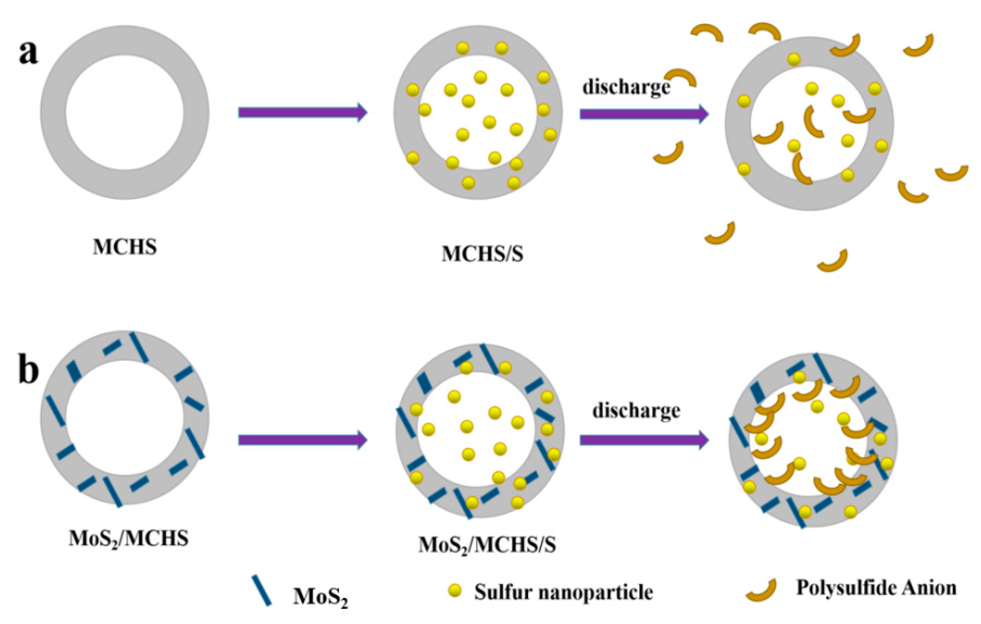
Scheme 1. Proposed adsorption mechanism of polysulfides for (a) the MCHS/S and (b) MoS2/MCHS/S electrodes.
Nanomaterials 09 01247 sch001
Figure 1. (a) X-ray diffraction patterns of the MoS2/MCHS and MCHS structures. (b) Heat curve of MoS2/MCHS composite structure.
Nanomaterials 09 01247 g001
Figure 2. (a,b) Scanning electron microscopy image of MoS2/MCHS. (c) Energy dispersive spectrometer mapping images of the MoS2/MCHS composite structures. (d) Transmission electron microscopy images and (e,f) High-resolution transmission electron microscopy of MoS2/MCHS.
Nanomaterials 09 01247 g002
Figure 3. Nitrogen adsorption–desorption isotherm curves (a) and corresponding pore size distribution plots (b) of the MoS2/MCHS and MCHS structures.
Nanomaterials 09 01247 g003
Figure 4. X-ray photoelectron spectroscopy spectrum of the MoS2/MCHS structures (a). High-resolution XPS spectra of Mo 3d-S 2s (b), S 2p (c), and C 1s (d).of the MoS2/MCHS structures.
Nanomaterials 09 01247 g004
Figure 5. Typical Cyclic voltammetry (CV) curves of (a) the MoS2/MCHS/S cathode and (b) CV curves of the MoS2/MCHS/S and MCHS/S electrodes at a scan rate of 0.1 mV s−1 in the second cycle.
Nanomaterials 09 01247 g005
Figure 6. The galvanostatic charge and discharge curves of the MoS2/MCHS/S electrode (a) and MCHS/S electrode (b) at various currents. Cycling performance of the MCHS/S and MoS2/MCHS/S cathodes at 0.2 C (c) and 2 C (d).
Nanomaterials 09 01247 g006