Effect of Graphene Nanosheets Content on Microstructure and Mechanical Properties of Titanium Matrix Composite Produced by Cold Pressing and Sintering


Abstract
:1. Introduction
2. Materials and Methods
3. Results and Discussion
3.1. Density
3.2. XRD Analysis
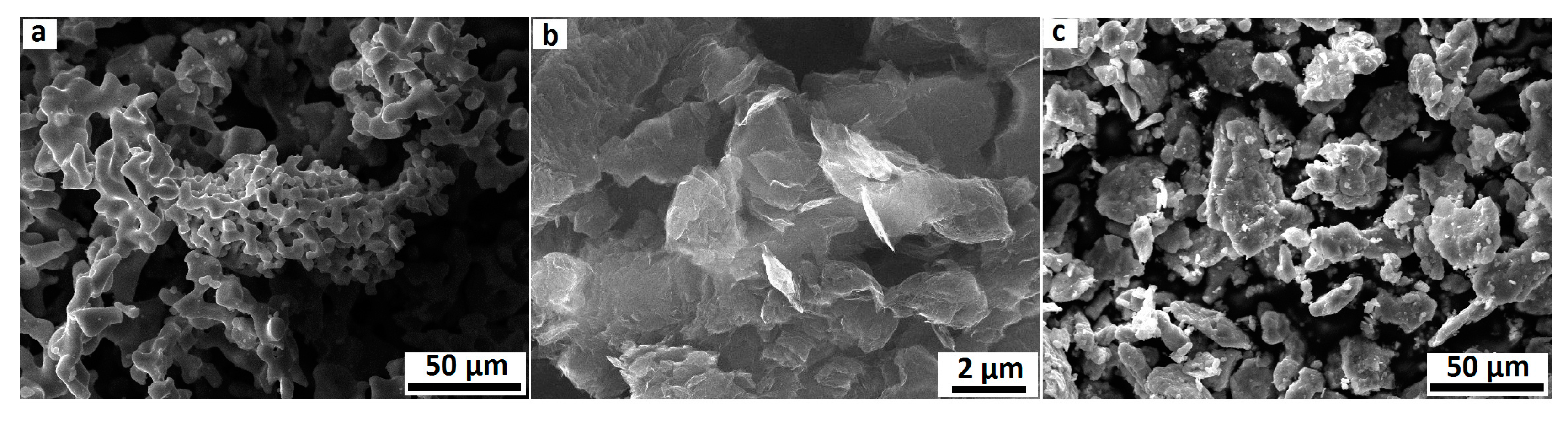
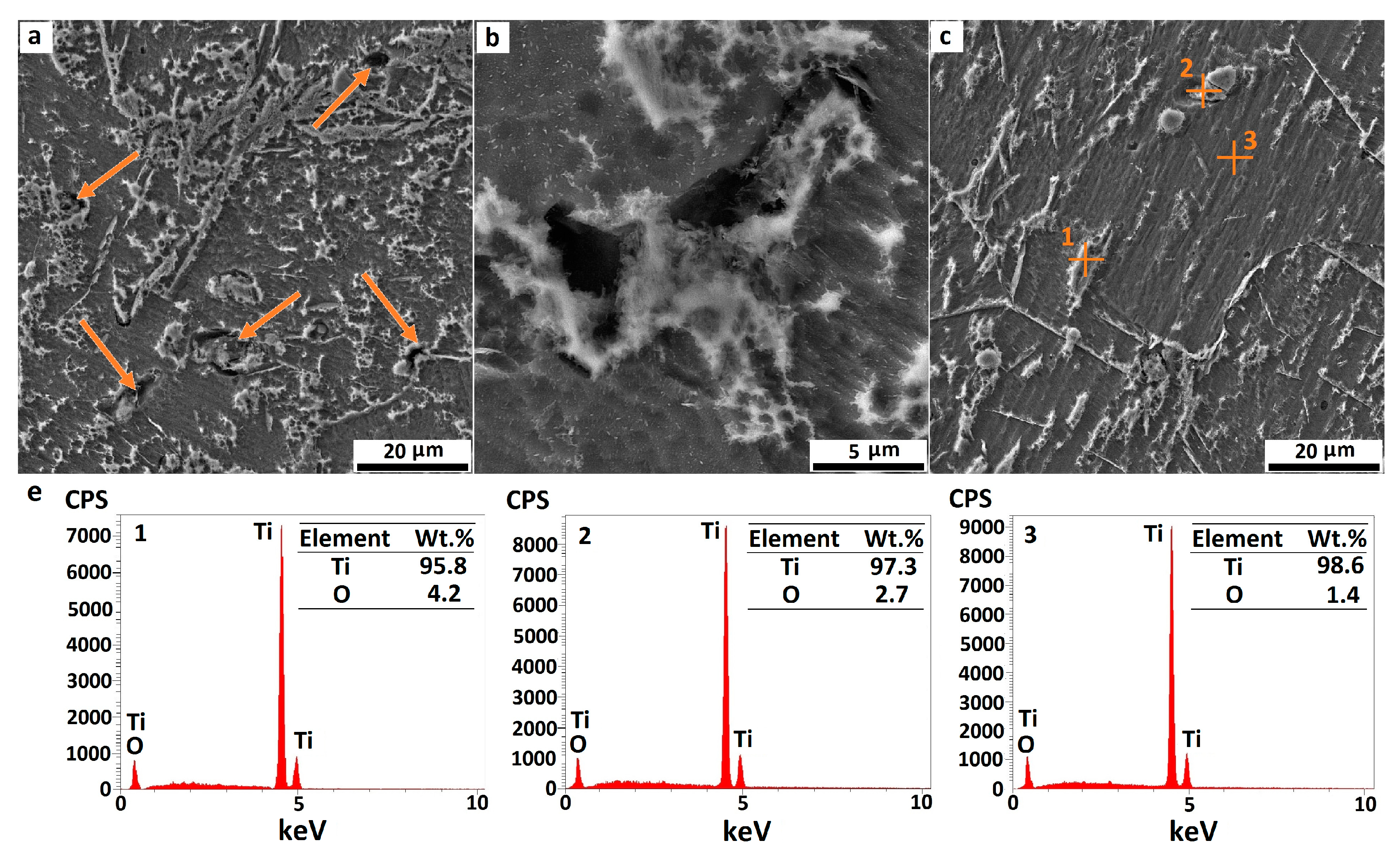
3.3. Microstructure Characterization by FESEM
3.4. Mechanical Properties
3.4.1. Microhardness
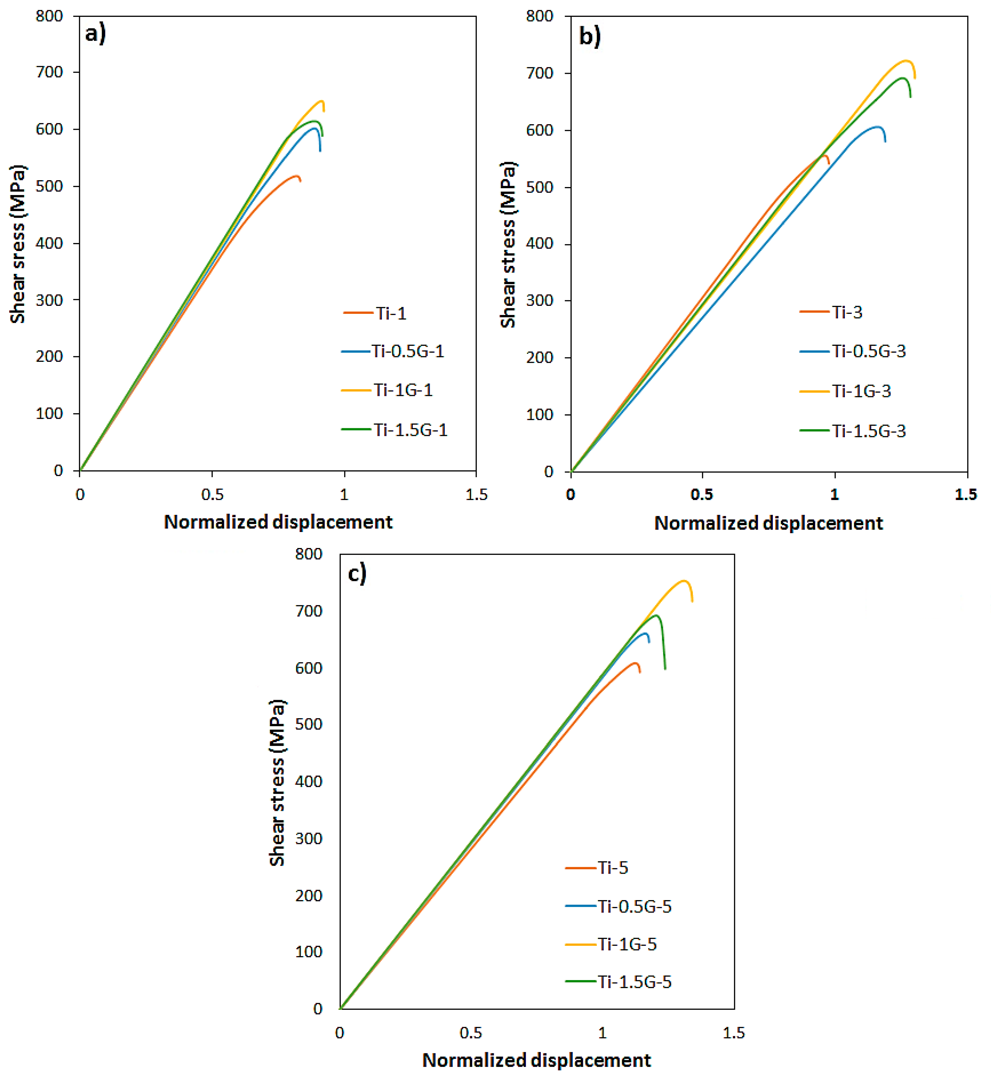
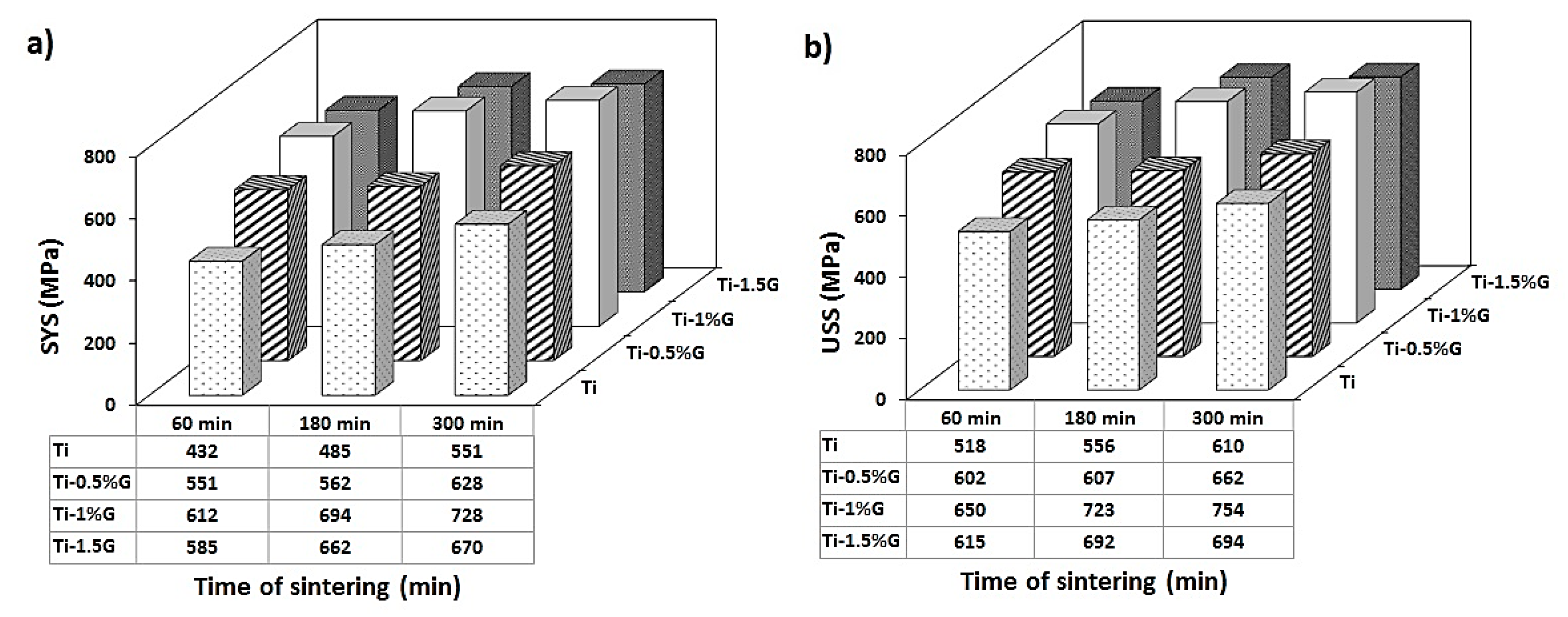
3.4.2. Shear Stress
4. Conclusions
- The density measurement by Archimedes’ method showed that by increasing sintering time, the density of the samples enhanced reasonably, while increasing the weight percentage of GNSs caused a slight reduction of density. Ti/GNS composites with a reasonable high density (more than 99.5% of theoretical density) were fabricated after sintering for 5 h.
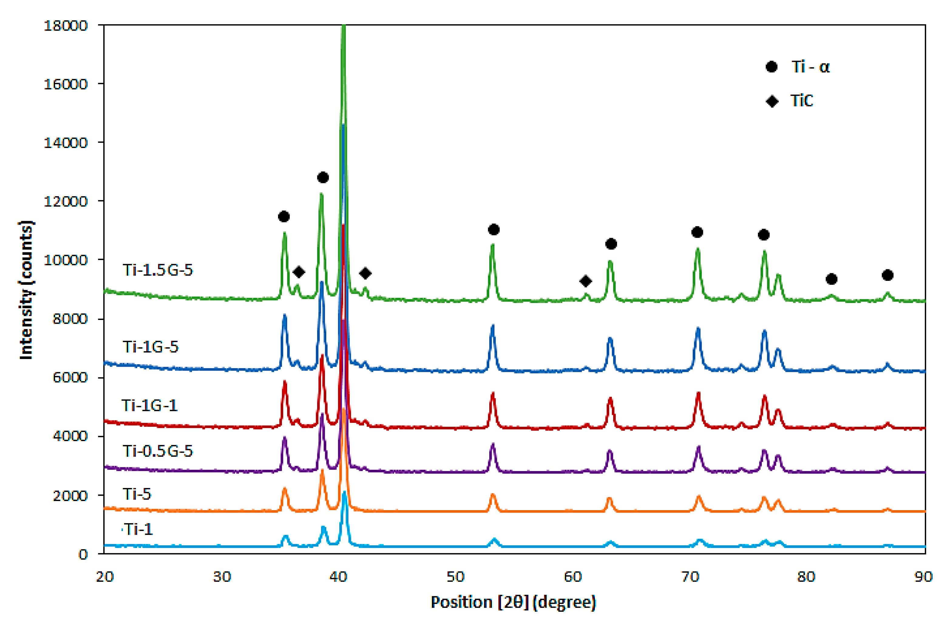
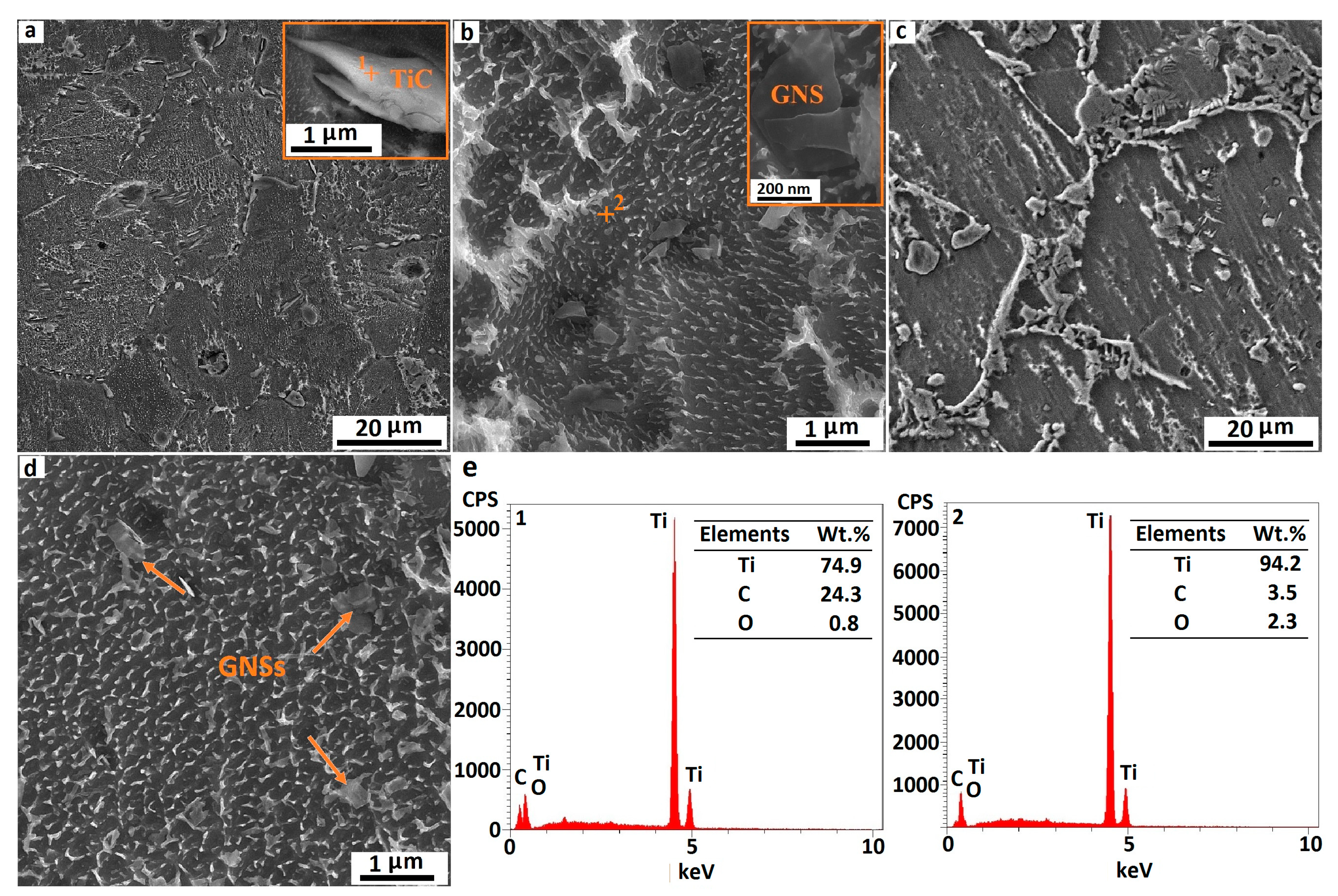
- XRD and SEM investigations confirmed the formation of TiC particles in the titanium/GNS composites due to the reaction of GNSs with the titanium matrix, which played an effective role in improving the mechanical properties of the composites. SEM images also revealed that an increase in the weight percentage of GNSs as well as sintering time resulted in the formation of a larger volume fraction of TiC particles. On the other hand, the outstanding unreacted GNSs remaining in the microstructure were also effective in the enhancement of mechanical properties of the composites.
- A characterization of the microstructure by SEM demonstrated that the excessive content of GNSs in composites containing 1.5 wt. % GNSs resulted in the agglomeration of GNSs and TiC particles in the microstructure and consequently, the improvement of mechanical properties reduced drastically.
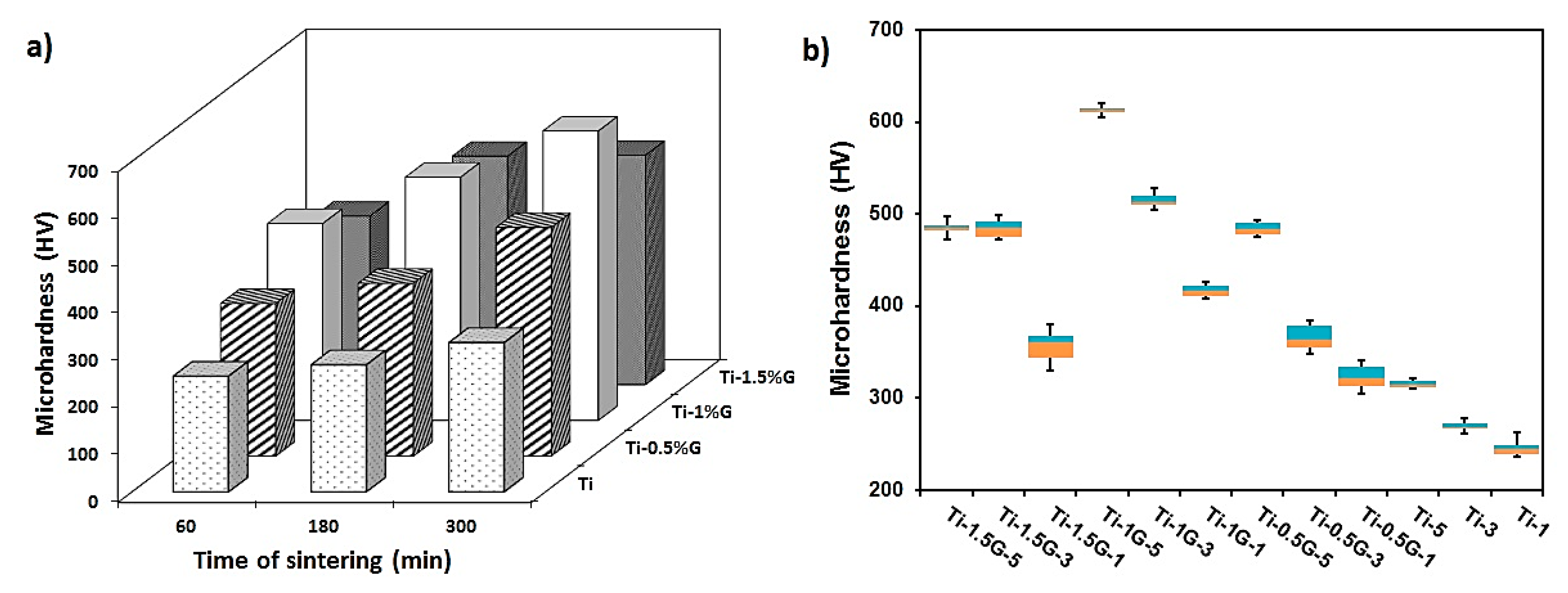
- Mechanical properties experiments revealed that an increase in GNS content up to 1 wt. % and an increment of the sintering time caused an enhancement in the microhardness and shear strength of the composites. Microhardness, shear yield strength, and ultimate shear strength of the composite containing 1 wt. % GNSs sintered for 5 h which possessed the highest mechanical properties were 613 HV, 728 MPa, and 754 MPa, respectively.
Author Contributions
Funding
Conflicts of Interest
References
- Casati, R.; Vedani, M. Metal matrix composites reinforced by nano-particles—A review. Metals 2014, 4, 65–83. [Google Scholar] [CrossRef]
- Lu, K. The future of metals. Science 2010, 328, 319–320. [Google Scholar] [CrossRef] [PubMed]
- Smith, P.R.; Froes, F.H. Titanium Metal-Matrix Composites. US4499156A, 12 February 1985. [Google Scholar]
- Kaczmar, J.; Pietrzak, K.; Włosiński, W. The production and application of metal matrix composite materials. J. Mater. Process. Technol. 2000, 106, 58–67. [Google Scholar] [CrossRef]
- Kainer, K.U. Metal Matrix Composites: Custom-Made Materials for Automotive and Aerospace Engineering; John Wiley & Sons: Hoboken, NJ, USA, 2006. [Google Scholar]
- Leyens, C.; Peters, M. Titanium and Titanium Alloys: Fundamentals and Applications; John Wiley & Sons: Hoboken, NJ, USA, 2003. [Google Scholar]
- Xu, R.; Liu, B.; Liu, Y.; Cao, Y.; Guo, W.; Nie, Y.; Liu, S. High Temperature Deformation Behavior of In-Situ Synthesized Titanium-Based Composite Reinforced with Ultra-Fine TiB Whiskers. Materials 2018, 11, 1863. [Google Scholar] [CrossRef] [PubMed]
- Wang, Z.; Li, M.L.; Shen, Q.; Zhang, L.M. Fabrication of Ti/Al2O3 composites by spark plasma sintering. In Key Engineering Materials; Trans Tech Publications: Zurich-Uetikon, Switzerland, 2003. [Google Scholar]
- Lisiecki, A. Titanium matrix composite Ti/TiN produced by diode laser gas nitriding. Metals 2015, 5, 54–69. [Google Scholar] [CrossRef]
- Edalati, E.; Sajjadi, S.A.; Babakhani, A. Effects of SiC Nanoparticles on the Properties of Titanium-Matrix Foams Processed by Powder Metallurgy. Metals 2017, 7, 296. [Google Scholar] [CrossRef]
- Kuang, D.; Xu, L.; Liu, L.; Hu, W.; Wu, Y. Graphene–nickel composites. Appl. Surf. Sci. 2013, 273, 484–490. [Google Scholar] [CrossRef]
- Lu, W.; Zhang, D.; Zhang, X.; Wu, R.; Sakata, T.; Mori, H. HREM study of TiB/Ti interfaces in a TiB-TiC in situ composite. Scr. Mater. 2001, 44, 1069–1075. [Google Scholar] [CrossRef]
- Tjong, S.C. Recent progress in the development and properties of novel metal matrix nanocomposites reinforced with carbon nanotubes and graphene nanosheets. Mater. Sci. Eng. R Rep. 2013, 74, 281–350. [Google Scholar] [CrossRef]
- Young, R.J.; Kinloch, I.A.; Gong, L.; Novoselov, K.S. The mechanics of graphene nanocomposites: A review. Compos. Sci. Technol. 2012, 72, 1459–1476. [Google Scholar] [CrossRef]
- Kim, C.-H. Nanostructured graphene: An active component in optoelectronic devices. Nanomaterials 2018, 8, 328. [Google Scholar] [CrossRef] [PubMed]
- Mertens, R. The Graphene Handbook (2016 Edition); Lulu Press: Raleigh, NC, USA, 2016. [Google Scholar]
- Li, D.; Müller, M.B.; Gilje, S.; Kaner, R.B.; Wallace, G.G. Processable aqueous dispersions of graphene nanosheets. Nat. Nanotechnol. 2008, 3, 101. [Google Scholar] [CrossRef] [PubMed]
- Nakada, K.; Ishii, A. DFT calculation for adatom adsorption on graphene. In Graphene Simulation; InTech: Rijeka, Croatia, 2011. [Google Scholar]
- Chan, K.T.; Neaton, J.; Cohen, M.L. First-principles study of metal adatom adsorption on graphene. Phys. Rev. B 2008, 77, 235430. [Google Scholar] [CrossRef]
- Dimakis, N.; Flor, F.A.; Salgado, A.; Adjibi, K.; Vargas, S.; Saenz, J. Density functional theory calculations on transition metal atoms adsorbed on graphene monolayers. Appl. Surf. Sci. 2017, 421, 252–259. [Google Scholar] [CrossRef]
- Pérez-Bustamante, R.; Bolaños-Morales, D.; Bonilla-Martínez, J.; Estrada-Guel, I.; Martínez-Sánchez, R. Microstructural and hardness behavior of graphene-nanoplatelets/aluminum composites synthesized by mechanical alloying. J. Alloys Compd. 2014, 615, 578–582. [Google Scholar] [CrossRef]
- Hu, Z.; Chen, F.; Xu, J.; Nian, Q.; Lin, D.; Chen, C.; Zhu, X.; Chen, Y.; Zhang, M. 3D printing graphene-aluminum nanocomposites. J. Alloys Compd. 2018, 746, 269–276. [Google Scholar] [CrossRef]
- Du, X.; Du, W.; Wang, Z.; Liu, K.; Li, S. Ultra-high strengthening efficiency of graphene nanoplatelets reinforced magnesium matrix composites. Mater. Sci. Eng. A 2018, 711, 633–42. [Google Scholar] [CrossRef]
- Chen, L.; Zhao, Y.; Hou, H.; Zhang, T.; Liang, J.; Li, M.; Li, J. Development of AZ91D magnesium alloy-graphene nanoplatelets composites using thixomolding process. J. Alloys Compd. 2019, 788, 359–374. [Google Scholar] [CrossRef]
- Dai, H. Carbon Nanotubes: Synthesis, Structure, Properties, and Applications. In Topics in Applied Physics; Springer: Berlin, Germany, 2001. [Google Scholar]
- Westwood, A. Materials for advanced studies and devices. Metall. Trans. A 1988, 19, 749–758. [Google Scholar] [CrossRef]
- Ni, D.R.; Geng, L.; Zhang, J.; Zheng, Z.Z. Fabrication and tensile properties of in situ TiBw and TiCp hybrid-reinforced titanium matrix composites based on Ti–B4C–C. Mater. Sci. Eng. A 2008, 478, 291–296. [Google Scholar] [CrossRef]
- Wang, F.C.; Zhang, Z.H.; Sun, Y.J.; Liu, Y.; Hu, Z.Y.; Wang, H.; Korznikov, A.V.; Korznikova, E.; Liu, Z.F.; Osamu, S. Rapid and low temperature spark plasma sintering synthesis of novel carbon nanotube reinforced titanium matrix composites. Carbon 2015, 95, 396–407. [Google Scholar] [CrossRef]
- Kuzumaki, T.; Ujiie, O.; Ichinose, H.; Ito, K. Mechanical characteristics and preparation of carbon nanotube fiber-reinforced Ti composite. Adv. Eng. Mater. 2000, 2, 416–418. [Google Scholar] [CrossRef]
- Li, F.; Jiang, X.; Shao, Z.; Zhu, D.; Luo, Z. Microstructure and Mechanical Properties of Nano-Carbon Reinforced Titanium Matrix/Hydroxyapatite Biocomposites Prepared by Spark Plasma Sintering. Nanomaterials 2018, 8, 729. [Google Scholar] [CrossRef] [PubMed]
- Cao, Z.; Wang, X.; Li, J.; Wu, Y.; Zhang, H.; Guo, J.; Wang, S. Reinforcement with graphene nanoflakes in titanium matrix composites. J. Alloys Compd. 2017, 696, 498–502. [Google Scholar] [CrossRef]
- Mu, X.N.; Zhang, H.M.; Cai, H.N.; Fan, Q.B.; Zhang, Z.H.; Wu, Y.; Fu, Z.J.; Yu, D.H. Microstructure evolution and superior tensile properties of low content graphene nanoplatelets reinforced pure Ti matrix composites. Mater. Sci. Eng. A 2017, 687, 164–174. [Google Scholar] [CrossRef]
- Kim, W.; Lee, T.; Han, S. Multi-layer graphene/copper composites: Preparation using high-ratio differential speed rolling, microstructure and mechanical properties. Carbon 2014, 69, 55–65. [Google Scholar] [CrossRef]
- Ansarian, I.; Shaeri, M.H.; Ebrahimi, M.; Minárik, P.; Bartha, K. Microstructure evolution and mechanical behaviour of severely deformed pure titanium through multi directional forging. J. Alloys Compd. 2018. [Google Scholar] [CrossRef]
- Chegini, M.; Shaeri, M.H. Effect of equal channel angular pressing on the mechanical and tribological behavior of Al-Zn-Mg-Cu alloy. Mater. Charact. 2018, 140, 147–161. [Google Scholar] [CrossRef]
- Dashti, A.; Shaeri, M.H.; Taghiabadi, R.; Djavanroodi, F.; Ghazvini, F.V.; Javadi, H. Microstructure, Texture, Electrical and Mechanical Properties of AA-6063 Processed by Multi Directional Forging. Materials 2018, 11, 2419. [Google Scholar] [CrossRef]
- Sellamuthu, P.; Collins, P.K.; Hodgson, P.D.; Stanford, N. Correlation of tensile test properties with those predicted by the shear punch test. Mater. Des. 2013, 47, 258–266. [Google Scholar] [CrossRef]
- Mishra, S.K.; Pathak, L. Effect of carbon and titanium carbide on sintering behaviour of zirconium diboride. J. Alloys Compd. 2008, 465, 547–555. [Google Scholar] [CrossRef]
- Li, S.; Sun, B.; Imai, H.; Mimoto, T.; Kondoh, K. Powder metallurgy titanium metal matrix composites reinforced with carbon nanotubes and graphite. Compos. Part A Appl. Sci. Manuf. 2013, 48, 57–66. [Google Scholar] [CrossRef]
- Lu, W.J.; Zhang, D.; Zhang, X.N.; Wu, R.J.; Sakata, T.; Mori, H. Microstructure and tensile properties of in situ (TiB+ TiC)/Ti6242 (TiB: TiC= 1: 1) composites prepared by common casting technique. Mater. Sci. Eng. A 2001, 311, 142–150. [Google Scholar] [CrossRef]
- Zhang, Z.; Chen, D. Consideration of Orowan strengthening effect in particulate-reinforced metal matrix nanocomposites: A model for predicting their yield strength. Scr. Mater. 2006, 54, 1321–1326. [Google Scholar] [CrossRef]
- Chen, Y.; Balani, K.; Agarwal, A. Do thermal residual stresses contribute to the improved fracture toughness of carbon nanotube/alumina nanocomposites? Scr. Mater. 2012, 66, 347–350. [Google Scholar] [CrossRef]
- Sadowski, P.; Kowalczyk-Gajewska, K.; Stupkiewicz, S. Classical estimates of the effective thermoelastic properties of copper–graphene composites. Compos. Part B Eng. 2015, 80, 278–290. [Google Scholar] [CrossRef]
- Chu, K.; Jia, C. Enhanced strength in bulk graphene–copper composites. Physica Status Solidi (a) 2014, 211, 184–190. [Google Scholar] [CrossRef]
- Hu, Z.; Tong, G. Laser sintered thin layer graphene and cubic boron nitride reinforced nickel matrix nanocomposites. In Proceedings of the AOPC 2015: Micro/Nano Optical Manufacturing Technologies; and Laser Processing and Rapid Prototyping Techniques, Beijing, China, 15 October 2015. [Google Scholar]
- Threrujirapapong, T.; Kondoh, K.; Imai, H.; Umeda, J.; Fugetsu, B. Mechanical properties of a titanium matrix composite reinforced with low cost carbon black via powder metallurgy processing. Mater. Trans. 2009, 50, 2757–2762. [Google Scholar] [CrossRef]
- Vasanthakumar, K.; Karthiselva, N.S.; Chawake, N.M.; Bakshi, S.R. Formation of TiCx during reactive spark plasma sintering of mechanically milled Ti/carbon nanotube mixtures. J. Alloys Compd. 2017, 709, 829–841. [Google Scholar] [CrossRef]
- Roger, J.; Gardiola, B.; Andrieux, J.; Viala, J.C.; Dezellus, O. Synthesis of Ti matrix composites reinforced with TiC particles: Thermodynamic equilibrium and change in microstructure. J. Mater. Sci. 2017, 52, 4129–4141. [Google Scholar] [CrossRef]
- Kim, Y.-J.; Chung, H.; Kang, S.-J.L. Processing and mechanical properties of Ti–6Al–4V/TiC in situ composite fabricated by gas–solid reaction. Mater. Sci. Eng. A 2002, 333, 343–350. [Google Scholar] [CrossRef]
- Ma, F.; Zhou, J.; Liu, P.; Li, W.; Liu, X.; Pan, D.; Lu, W.; Zhang, D.; Wu, L.; Wei, X. Strengthening effects of TiC particles and microstructure refinement in in situ TiC-reinforced Ti matrix composites. Mater. Charact. 2017, 127, 27–34. [Google Scholar] [CrossRef]
- Nam, D.H.; Cha, S.I.; Lim, B.K.; Park, H.M.; Han, D.S.; Hong, S.H. Synergistic strengthening by load transfer mechanism and grain refinement of CNT/Al–Cu composites. Carbon 2012, 50, 2417–2423. [Google Scholar] [CrossRef]
- Chen, B.; Li, S.; Imai, H.; Jia, L.; Umeda, J.; Takahashi, M.; Kondoh, K. Load transfer strengthening in carbon nanotubes reinforced metal matrix composites via in-situ tensile tests. Compos. Sci. Technol. 2015, 113, 1–8. [Google Scholar] [CrossRef]
- George, R.; Kashyap, K.T.; Rahul, R.; Yamdagni, S. Strengthening in carbon nanotube/aluminium (CNT/Al) composites. Scr. Mater. 2005, 53, 1159–1163. [Google Scholar] [CrossRef]
- Proville, L.; Bakó, B. Dislocation depinning from ordered nanophases in a model fcc crystal: From cutting mechanism to Orowan looping. Acta Mater. 2010, 58, 5565–5571. [Google Scholar] [CrossRef]
- German, R.M. Powder Metallurgy Science; Metal Powder Industries Federation: Princeton, NJ, USA, 1984. [Google Scholar]
- Yoo, S.; Han, S.; Kim, W. Strength and strain hardening of aluminum matrix composites with randomly dispersed nanometer-length fragmented carbon nanotubes. Scr. Mater. 2013, 68, 711–714. [Google Scholar] [CrossRef]
- Dong, S.; Zhou, J.; Hui, D.; Wang, Y.; Zhang, S. Size dependent strengthening mechanisms in carbon nanotube reinforced metal matrix composites. Compos. Part A Appl. Sci. Manuf. 2015, 68, 356–364. [Google Scholar] [CrossRef]


| Samples | Time of Sintering (h) | Content of GNSs (wt. %) | Theoretical Density (g/cm3) | Experimental Density (g/cm3) | Percentage of Density (%) |
|---|---|---|---|---|---|
| Ti-1 | 1 | 0 | 4.506 | 4.382 | 97.2 |
| Ti-3 | 3 | 0 | 4.506 | 4.410 | 97.8 |
| Ti-5 | 5 | 0 | 4.506 | 4.476 | 99.3 |
| Ti-0.5G-1 | 1 | 0.5 | 4.480 | 4.345 | 97.0 |
| Ti-0.5G-3 | 3 | 0.5 | 4.480 | 4.395 | 98.1 |
| Ti-0.5G-5 | 5 | 0.5 | 4.480 | 4.467 | 99.7 |
| Ti-1G-1 | 1 | 1 | 4.450 | 4.337 | 97.5 |
| Ti-1G-3 | 3 | 1 | 4.450 | 4.388 | 98.6 |
| Ti-1G-5 | 5 | 1 | 4.450 | 4.440 | 99.7 |
| Ti-1.5G-1 | 1 | 1.5 | 4.420 | 4.275 | 96.7 |
| Ti-1.5G-3 | 3 | 1.5 | 4.420 | 4.301 | 97.3 |
| Ti-1.5G-5 | 5 | 1.5 | 4.420 | 4.334 | 98.1 |
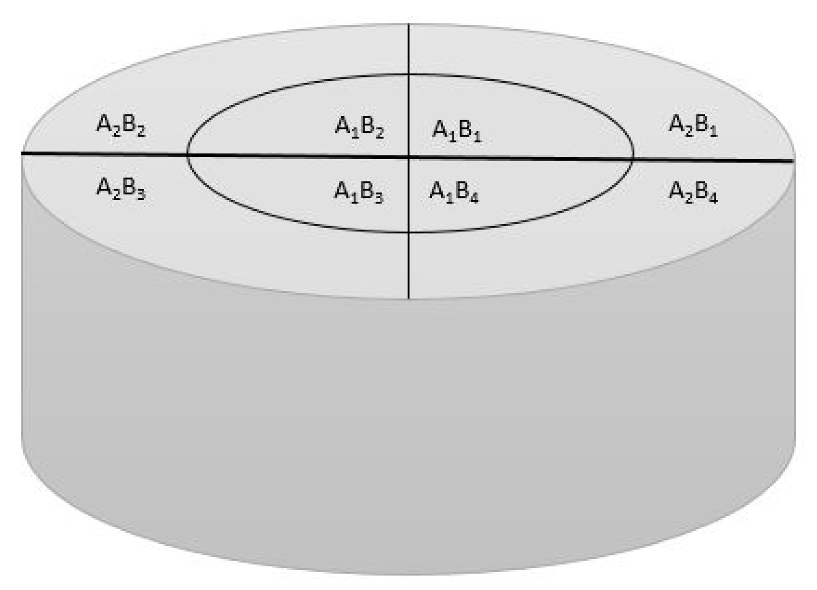
| Sample | Vickers Microhardness | ||||||||
|---|---|---|---|---|---|---|---|---|---|
| A1B1 | A1B2 | A1B3 | A1B4 | A2B1 | A2B2 | A2B3 | A2B4 | Average | |
| Ti-1 | 244 | 237 | 252 | 263 | 239 | 245 | 247 | 236 | 245 |
| Ti-3 | 271 | 268 | 266 | 275 | 278 | 268 | 269 | 259 | 269 |
| Ti-5 | 320 | 322 | 316 | 312 | 319 | 310 | 312 | 314 | 316 |
| Ti-0.5G-1 | 332 | 311 | 338 | 341 | 314 | 305 | 328 | 315 | 323 |
| Ti-0.5G-3 | 384 | 350 | 378 | 348 | 380 | 356 | 357 | 371 | 366 |
| Ti-0.5G-5 | 479 | 485 | 493 | 494 | 475 | 489 | 483 | 475 | 484 |
| Ti-1G-1 | 427 | 423 | 412 | 408 | 413 | 419 | 421 | 410 | 417 |
| Ti-1G-3 | 514 | 520 | 509 | 505 | 528 | 512 | 511 | 521 | 515 |
| Ti-1G-5 | 615 | 611 | 609 | 620 | 612 | 617 | 614 | 606 | 613 |
| Ti-1.5G-1 | 330 | 359 | 338 | 372 | 366 | 345 | 380 | 363 | 357 |
| Ti-1.5G-3 | 476 | 486 | 492 | 499 | 472 | 492 | 483 | 473 | 484 |
| Ti-1.5G-5 | 473 | 484 | 486 | 503 | 479 | 494 | 485 | 483 | 486 |
© 2018 by the authors. Licensee MDPI, Basel, Switzerland. This article is an open access article distributed under the terms and conditions of the Creative Commons Attribution (CC BY) license (http://creativecommons.org/licenses/by/4.0/).
Share and Cite
Haghighi, M.; Shaeri, M.H.; Sedghi, A.; Djavanroodi, F. Effect of Graphene Nanosheets Content on Microstructure and Mechanical Properties of Titanium Matrix Composite Produced by Cold Pressing and Sintering. Nanomaterials 2018, 8, 1024. https://doi.org/10.3390/nano8121024
Haghighi M, Shaeri MH, Sedghi A, Djavanroodi F. Effect of Graphene Nanosheets Content on Microstructure and Mechanical Properties of Titanium Matrix Composite Produced by Cold Pressing and Sintering. Nanomaterials. 2018; 8(12):1024. https://doi.org/10.3390/nano8121024
Chicago/Turabian StyleHaghighi, Milad, Mohammad Hossein Shaeri, Arman Sedghi, and Faramarz Djavanroodi. 2018. "Effect of Graphene Nanosheets Content on Microstructure and Mechanical Properties of Titanium Matrix Composite Produced by Cold Pressing and Sintering" Nanomaterials 8, no. 12: 1024. https://doi.org/10.3390/nano8121024
APA StyleHaghighi, M., Shaeri, M. H., Sedghi, A., & Djavanroodi, F. (2018). Effect of Graphene Nanosheets Content on Microstructure and Mechanical Properties of Titanium Matrix Composite Produced by Cold Pressing and Sintering. Nanomaterials, 8(12), 1024. https://doi.org/10.3390/nano8121024