
Simple Technique of Exfoliation and Dispersion of Multilayer Graphene from Natural Graphite by Ozone-Assisted Sonication


Abstract
:
1. Introduction
2. Materials and Methods
2.1. Materials
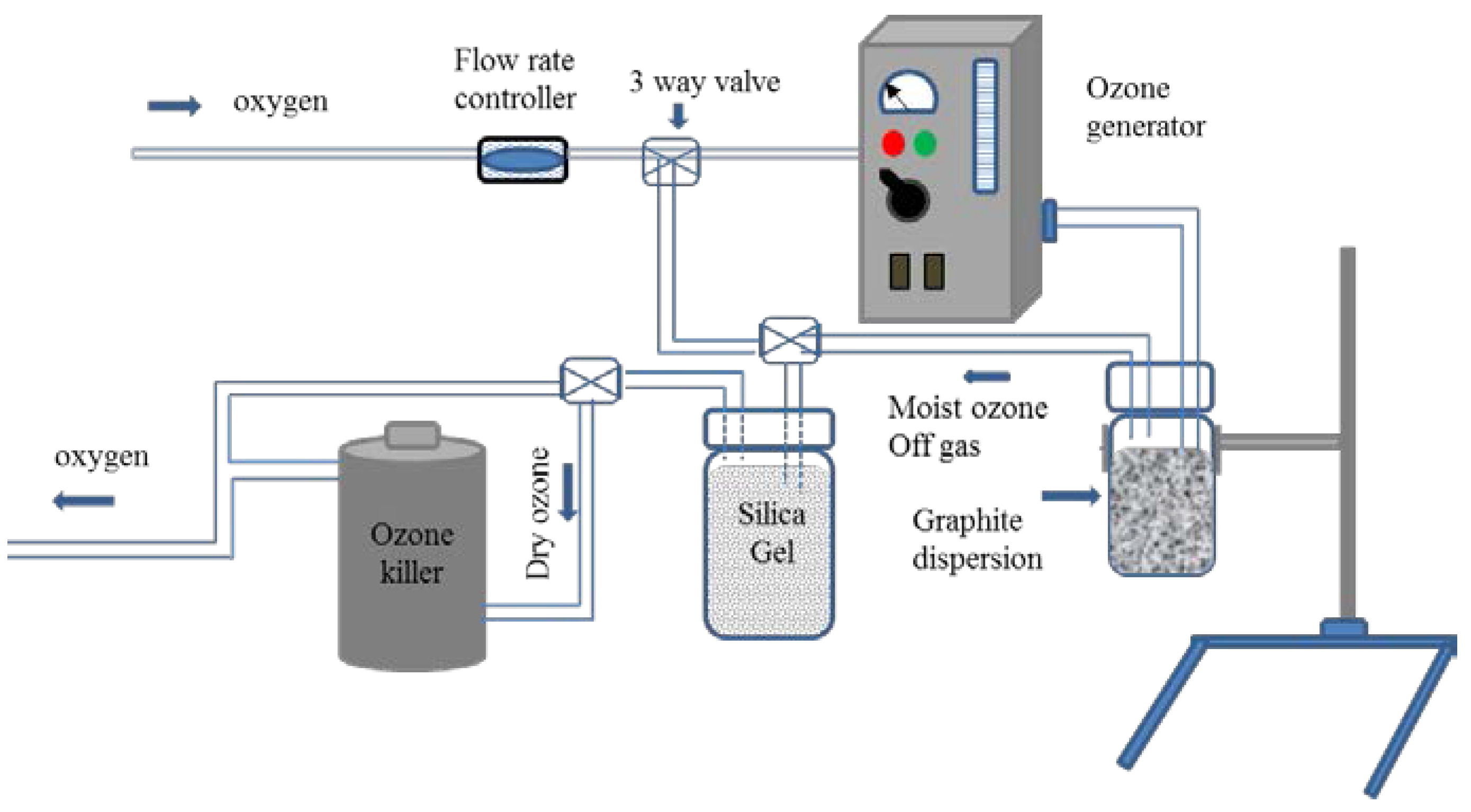
2.2. Experimental Setup for the Ozone Treatment
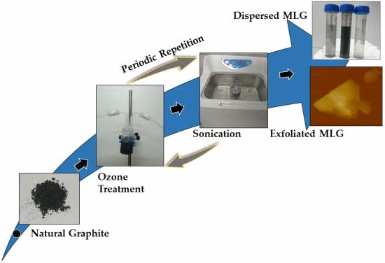
2.3. Graphite Exfoliation by Sonication
2.4. Characterization
3. Results and Discussion
4. Conclusions
Acknowledgments
Author Contributions
Conflicts of Interest
References
- Geim, A.K.; Novoselov, K.S. The rise of graphene. Nat. Mater. 2007, 6, 183–191. [Google Scholar] [CrossRef] [PubMed]
- Singh, V.; Joung, D.; Zhai, L.; Das, S.; Khondaker, S.I.; Seal, S. Graphene based materials: Past, present and future. Prog. Mater. Sci. 2011, 56, 1178–1271. [Google Scholar] [CrossRef]
- Novoselov, K.S.; Falko, V.I.; Colombo, L.; Gellert, P.R.; Schwab, M.G.; Kim, K. A roadmap for graphene. Nature 2012, 490, 192–200. [Google Scholar] [CrossRef] [PubMed]
- Fuhrer, M.S.; Lau, C.N.; MacDonald, A.H. Graphene: Materially better carbon. MRS Bull. 2011, 35, 289–295. [Google Scholar] [CrossRef]
- Soldano, C.; Mahmood, A.; Dujardin, E. Production, properties and potential of graphene. Carbon 2010, 48, 2127–2150. [Google Scholar] [CrossRef]
- Vermisoglou, E.C.; Giannakopoulou, T.; Romanos, G.; Boukos, N.; Psycharis, V.; Lei, C.; Lekakou, C.; Petridis, D.; Trapalis, C. Graphene-based materials via benzidine-assisted exfoliation and reduction of graphite oxide and their electrochemical properties. Appl. Surf. Sci. 2017, 392, 244–255. [Google Scholar] [CrossRef]
- Rasheed, A.K.; Khalid, M.; Rashmi, W.; Gupta, T.C.S.M.; Chan, A. Graphene based nanofluids and nanolubricants—Review of recent developments. Renew. Sustain. Energy Rev. 2016, 63, 346–362. [Google Scholar] [CrossRef]
- Paton, K.R.; Varrla, E.; Backes, C.; Smith, R.J.; Khan, U.; O’Neill, A.; Boland, C.; Lotya, M.; Istrate, O.M.; King, P.; et al. Scalable production of large quantities of defect-free few-layer graphene by shear exfoliation in liquids. Nat. Mater. 2014, 13, 624–630. [Google Scholar] [CrossRef] [PubMed]
- Lee, H.C.; Liu, W.W.; Chai, S.-P.; Mohamed, A.R.; Lai, C.W.; Khe, C.S.; Voon, C.H.; Hashim, U.; Hidayah, N.M.S. Synthesis of single-layer graphene: A review of recent development. Proced. Chem. 2016, 19, 916–921. [Google Scholar] [CrossRef]
- Abdolhosseinzadeh, S.; Asgharzadeh, H.; Seop Kim, H. Fast and fully-scalable synthesis of reduced graphene oxide. Sci. Rep. 2015, 5, 10160. [Google Scholar] [CrossRef] [PubMed]
- Jacobberger, R.M.; Machhi, R.; Wroblewski, J.; Taylor, B.; Gillian-Daniel, A.L.; Arnold, M.S. Simple graphene synthesis via chemical vapor deposition. J. Chem. Educ. 2015, 92, 1903–1907. [Google Scholar] [CrossRef]
- Pei, S.; Cheng, H.M. The reduction of graphene oxide. Carbon 2012, 50, 3210–3228. [Google Scholar] [CrossRef]
- Backes, C.; Higgins, T.M.; Kelly, A.; Boland, C.; Harvey, A.; Hanlon, D.; Coleman, J.N. Guidelines for exfoliation, characterization and processing of layered materials produced by liquid exfoliation. Chem. Mater. 2017, 29, 243–255. [Google Scholar] [CrossRef]
- Haar, S.; Bruna, M.; Lian, J.X.; Tomarchio, F.; Olivier, Y.; Mazzaro, R.; Morandi, V.; Moran, J.; Ferrari, A.C.; Beljonne, D.; et al. Liquid-phase exfoliation of graphite into single- and few-layer graphene with α-functionalized alkanes. J. Phys. Chem. Lett. 2016, 7, 2714–2721. [Google Scholar] [CrossRef] [PubMed]
- Pavlova, A.S.; Obraztsova, E.A.; Belkin, A.V.; Monat, C.; Rojo-Romeo, P.; Obraztsova, E.D. Liquid-phase exfoliation of flaky graphite. J. Nanophotonics 2016, 10, 012525. [Google Scholar] [CrossRef]
- Haar, S.; El Gemayel, M.; Shin, Y.; Melinte, G.; Squillaci, M.A.; Ersen, O.; Casiraghi, C.; Ciesielski, A.; Samorì, P. Enhancing the liquid-phase exfoliation of graphene in organic solvents upon addition of n-octylbenzene. Sci. Rep. 2015, 5, 16684. [Google Scholar] [CrossRef] [PubMed]
- Tang, X.F.; Yang, Z.G.; Liang, J.H. Efficient strategy of chlorine-assisted liquid-phase exfoliation of graphite. J. Mater. Sci. 2017, 52, 3786–3793. [Google Scholar] [CrossRef]
- Nawaz, K.; Ayub, M.; Khan, M.B.; Hussain, A.; Malik, A.Q.; Niazi, M.B.K.; Hussain, M.; Khan, A.U.; Ul-Haq, N. Effect of concentration of surfactant on the exfoliation of graphite to graphene in aqueous media. Nanomater. Nanotechnol. 2016, 6, 14. [Google Scholar] [CrossRef]
- Narayan, R.; Kim, S.O. Surfactant mediated liquid phase exfoliation of graphene. Nano Converg. 2015, 2, 20. [Google Scholar] [CrossRef] [PubMed]
- Lotya, M.; Hernandez, Y.; King, P.J.; Smith, R.J.; Nicolosi, V.; Karlsson, L.S.; Blighe, F.M.; De, S.; Wang, Z.; McGovern, I.T.; et al. Liquid phase production of graphene by exfoliation of graphite in surfactant/water solutions. J. Am. Chem. Soc. 2009, 131, 3611–3620. [Google Scholar] [CrossRef] [PubMed]
- Chang, D.W.; Baek, J.-B. Eco-friendly synthesis of graphene nanoplatelets. J. Mater. Chem. A 2016, 4, 15281–15293. [Google Scholar] [CrossRef]
- Subramanya, B.; Bhat, D.K. Novel eco-friendly synthesis of graphene directly from graphite using 2,2,6,6-tetramethylpiperidine 1-oxyl and study of its electrochemical properties. J. Power Sour. 2015, 275, 90–98. [Google Scholar] [CrossRef]
- Coros, M.; Pogacean, F.; Rosu, M.C.; Socaci, C.; Borodi, G.; Magerusan, L.; Biris, A.R.; Pruneanu, S. Simple and cost-effective synthesis of graphene by electrochemical exfoliation of graphite rods. RSC Adv. 2016, 6, 2651–2661. [Google Scholar] [CrossRef]
- Araujo, P.T.; Terrones, M.; Dresselhaus, M.S. Defects and impurities in graphene-like materials. Mater. Today 2012, 15, 98–109. [Google Scholar] [CrossRef]
- Haldar, S.; Sanyal, B. Defects in graphene and its derivatives. In Recent Advances in Graphene Research; Nayak, P.K., Ed.; InTech: Rijeka, Croatia, 2016; Chapter 10. [Google Scholar]
- Zhong, Y.L.; Tian, Z.; Simon, G.P.; Li, D. Scalable production of graphene via wet chemistry: Progress and challenges. Mater. Today 2015, 18, 73–78. [Google Scholar] [CrossRef]
- Yu, P.; Lowe, S.E.; Simon, G.P.; Zhong, Y.L. Electrochemical exfoliation of graphite and production of functional graphene. Curr. Opin. Coll. Interface Sci. 2015, 20, 329–338. [Google Scholar] [CrossRef]
- Machuno, L.G.B.; Oliveira, A.R.; Furlan, R.H.; Lima, A.B.; Morais, L.C.; Gelamo, R.V. Multilayer graphene films obtained by dip coating technique. Mater. Res. 2015, 18, 775–780. [Google Scholar] [CrossRef]
- Ali, J.; Siddiqui, G.U.D.; Yang, Y.J.; Lee, K.T.; Um, K.; Choi, K.H. Direct synthesis of graphene quantum dots from multilayer graphene flakes through grinding assisted co-solvent ultrasonication for all-printed resistive switching arrays. RSC Adv. 2016, 6, 5068–5078. [Google Scholar] [CrossRef]
- Ricardo, K.B.; Sendecki, A.; Liu, H. Surfactant-free exfoliation of graphite in aqueous solutions. Chem. Commun. 2014, 50, 2751–2754. [Google Scholar] [CrossRef] [PubMed]
- Bepete, G.; Anglaret, E.; Ortolani, L.; Morandi, V.; Huang, K.; Pénicaud, A.; Drummond, C. Surfactant-free single-layer graphene in water. Nat. Chem. 2017, 9, 347–352. [Google Scholar] [CrossRef] [PubMed]
- Kim, J.; Kwon, S.; Cho, D.H.; Kang, B.; Kwon, H.; Kim, Y.; Park, S.O.; Jung, G.Y.; Shin, E.; Kim, W.-G.; et al. Direct exfoliation and dispersion of two-dimensional materials in pure water via temperature control. Nat. Commun. 2015, 6, 8294. [Google Scholar] [CrossRef] [PubMed]
- Han, J.T.; Jang, J.I.; Kim, H.; Hwang, J.Y.; Yoo, H.K.; Woo, J.S.; Choi, S.; Kim, H.Y.; Jeong, H.J.; Jeong, S.Y.; et al. Extremely efficient liquid exfoliation and dispersion of layered materials by unusual acoustic cavitation. Sci. Rep. 2014, 4, 5133. [Google Scholar] [CrossRef] [PubMed]
- Yi, M.; Shen, Z. A review on mechanical exfoliation for the scalable production of graphene. J. Mater. Chem. A 2015, 3, 11700–11715. [Google Scholar] [CrossRef]
- Park, M.H.; Kim, T.H.; Yang, C.-W. Thickness contrast of few-layered graphene in sem. Surf. Interface Anal. 2012, 44, 1538–1541. [Google Scholar] [CrossRef]
- Shioyama, H. The interactions of two chemical species in the interlayer spacing of graphite. Synth. Metals 2000, 114, 1–15. [Google Scholar] [CrossRef]


| Sample | Concentration (Atomic Weight %) | |
|---|---|---|
| Carbon | Oxygen | |
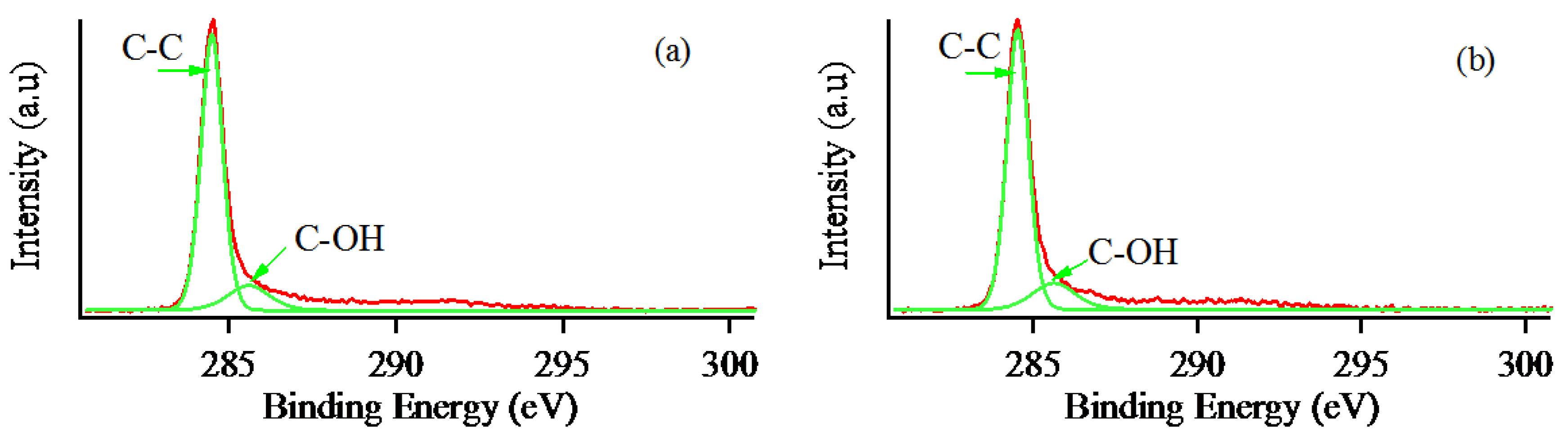
| Pristine natural graphite | 97.23 | 2.77 |
| Multilayer graphene | 95.52 | 4.48 |
© 2017 by the authors. Licensee MDPI, Basel, Switzerland. This article is an open access article distributed under the terms and conditions of the Creative Commons Attribution (CC BY) license (http://creativecommons.org/licenses/by/4.0/).
Share and Cite
Lin, Z.; Karthik, P.S.; Hada, M.; Nishikawa, T.; Hayashi, Y. Simple Technique of Exfoliation and Dispersion of Multilayer Graphene from Natural Graphite by Ozone-Assisted Sonication. Nanomaterials 2017, 7, 125. https://doi.org/10.3390/nano7060125
Lin Z, Karthik PS, Hada M, Nishikawa T, Hayashi Y. Simple Technique of Exfoliation and Dispersion of Multilayer Graphene from Natural Graphite by Ozone-Assisted Sonication. Nanomaterials. 2017; 7(6):125. https://doi.org/10.3390/nano7060125
Chicago/Turabian StyleLin, Zaw, Paneer Selvam Karthik, Masaki Hada, Takeshi Nishikawa, and Yasuhiko Hayashi. 2017. "Simple Technique of Exfoliation and Dispersion of Multilayer Graphene from Natural Graphite by Ozone-Assisted Sonication" Nanomaterials 7, no. 6: 125. https://doi.org/10.3390/nano7060125
APA StyleLin, Z., Karthik, P. S., Hada, M., Nishikawa, T., & Hayashi, Y. (2017). Simple Technique of Exfoliation and Dispersion of Multilayer Graphene from Natural Graphite by Ozone-Assisted Sonication. Nanomaterials, 7(6), 125. https://doi.org/10.3390/nano7060125