
Enhancing the Performance of LLO Through Vanadium Doping and Abundant Exposed (010) Planes in Secondary Particles


Abstract
1. Introduction
2. Materials and Methods
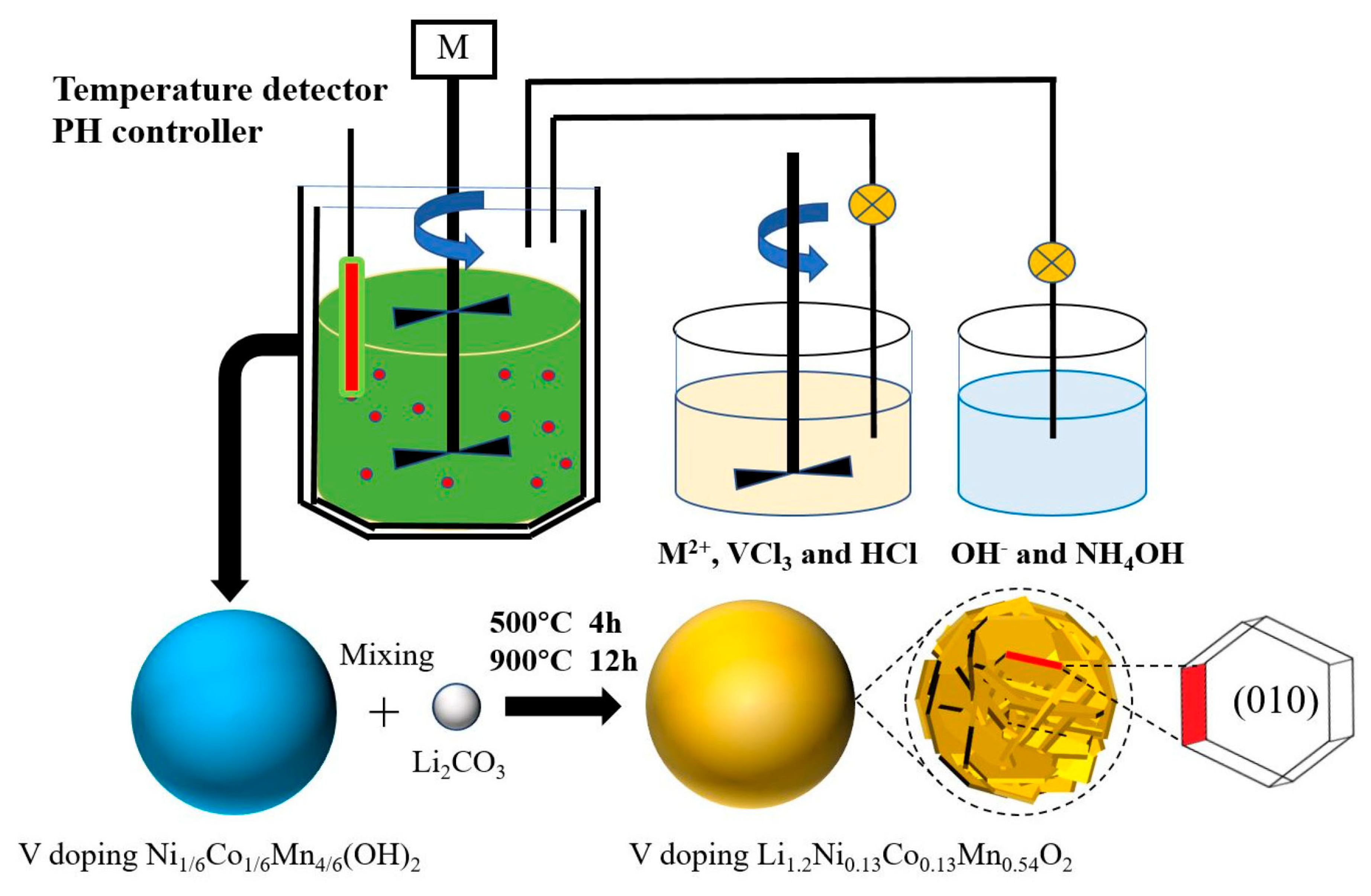
2.1. Material Preparation
2.2. Material Characterization
2.3. Electrochemical Measurements
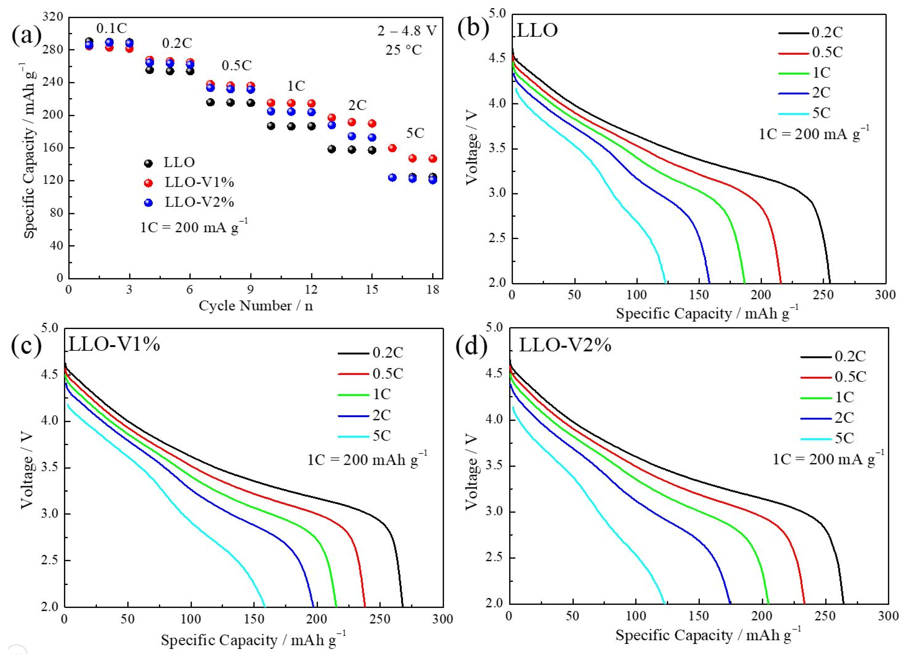
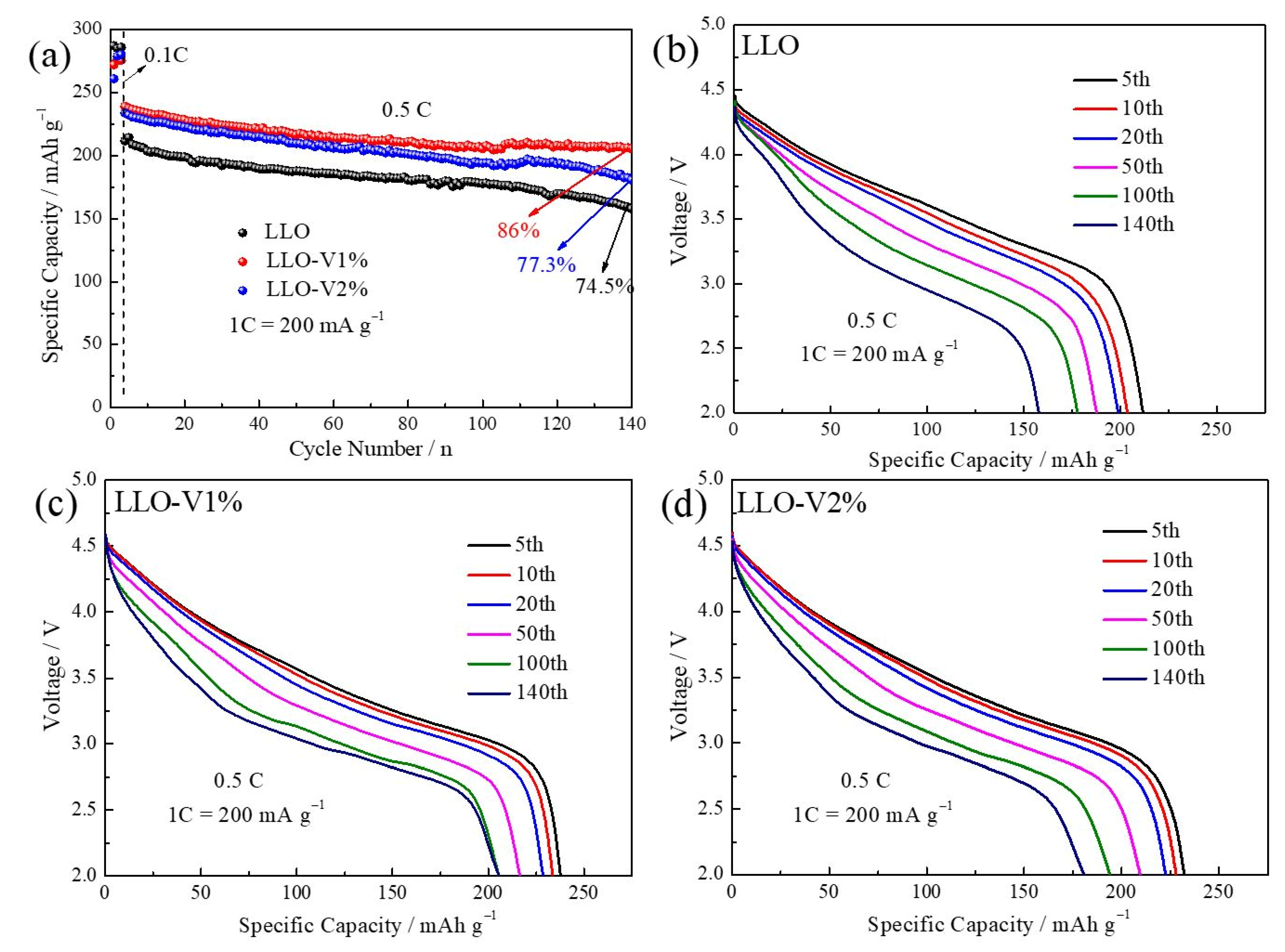
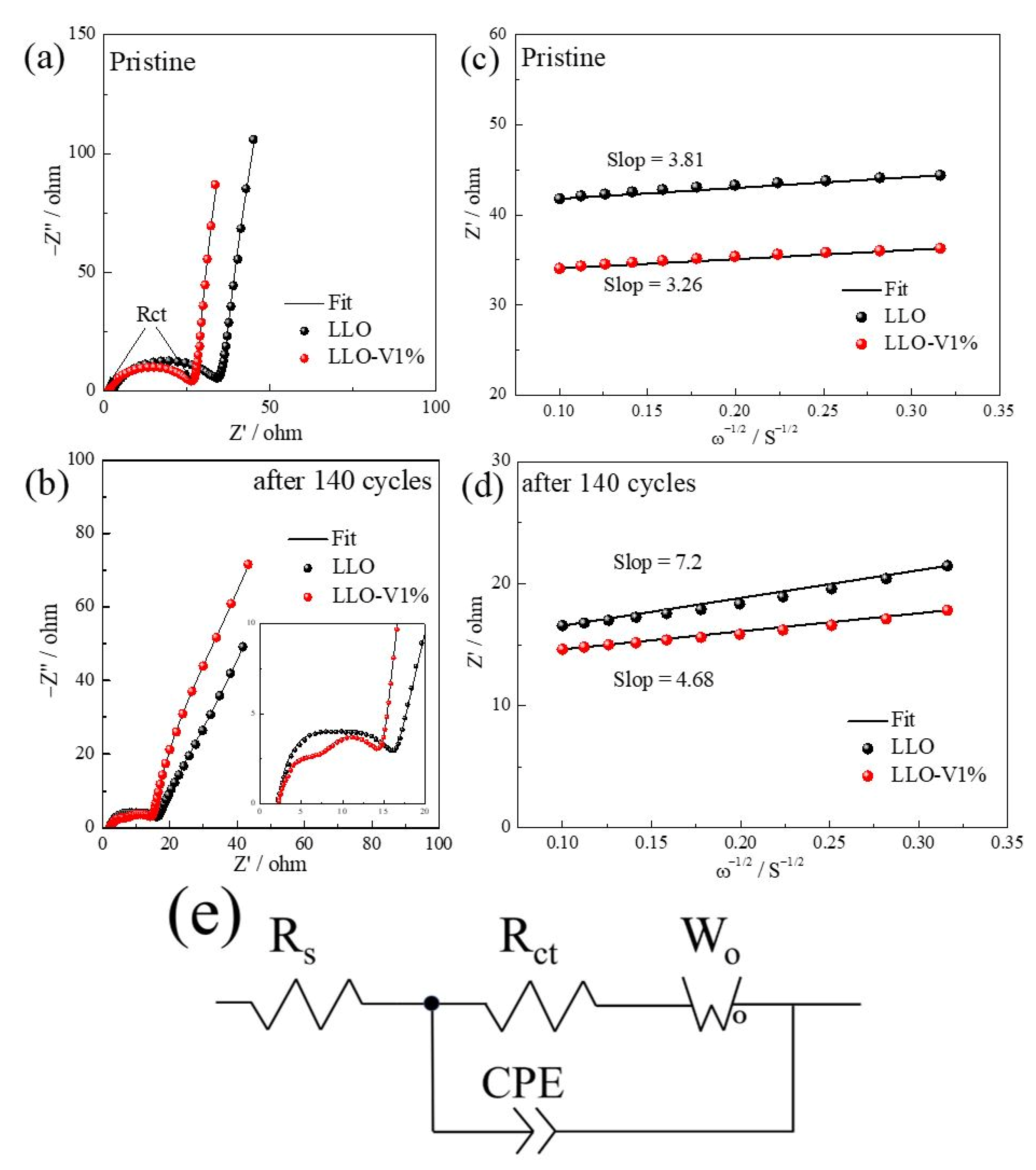
3. Results
4. Conclusions
Author Contributions
Funding
Data Availability Statement
Acknowledgments
Conflicts of Interest
References
- Tarascon, J.M.; Armand, M. Issues and challenges facing rechargeable lithium batteries. Nature 2001, 414, 359–367. [Google Scholar] [CrossRef] [PubMed]
- Dunn, B.; Kamath, H.; Tarascon, J.M. Electrical Energy Storage for the Grid: A Battery of Choices. Science 2011, 334, 928–935. [Google Scholar] [CrossRef] [PubMed]
- Chen, Z.L.; Zhang, Q.; Liang, Q.J. Carbon-Coatings Improve Performance of Li-Ion Battery. Nanomaterials 2022, 12, 1936. [Google Scholar] [CrossRef]
- Nie, L.; Chen, S.J.; Liu, W. Challenges and strategies of LLO for Li-ion batteries. Nano Res. 2023, 16, 391–402. [Google Scholar] [CrossRef]
- Zhao, S.Q.; Yan, K.; Zhang, J.Q.; Sun, B.; Wang, G.X. Reaction Mechanisms of Layered Lithium-Rich Cathode Materials for High-Energy Lithium-Ion Batteries. Angew. Chem.-Int. Ed. 2021, 60, 2208–2220. [Google Scholar] [CrossRef]
- Lu, H.Y.; Hou, R.L.; Chu, S.Y.; Zhou, H.S.; Guo, S.H. Progress on Modification Strategies of Layered Lithium-Rich Cathode Materials for High Energy Lithium-Ion Batteries. Acta Phys.-Chim. Sin. 2023, 39, 2211057. [Google Scholar] [CrossRef]
- Thackeray, M.M.; Kang, S.H.; Johnson, C.S.; Vaughey, J.T.; Benedek, R.; Hackney, S.A. Li2MnO3-stabilized LiMO2 (M = Mn, Ni, Co) electrodes for lithium-ion batteries. J. Mater. Chem. 2007, 17, 3112–3125. [Google Scholar] [CrossRef]
- Carroll, K.J.; Qian, D.; Fell, C.; Calvin, S.; Veith, G.M.; Chi, M.F.; Baggetto, L.; Meng, Y.S. Probing the electrode/electrolyte interface in the lithium excess layered oxide Li1.2Ni0.2Mn0.6O2. Phys. Chem. Chem. Phys. 2013, 15, 11128–11138. [Google Scholar] [CrossRef]
- Gu, M.; Belharouak, I.; Zheng, J.M.; Wu, H.M.; Xiao, J.; Genc, A.; Amine, K.; Thevuthasan, S.; Baer, D.R.; Zhang, J.G.; et al. Formation of the Spinel Phase in the Layered Composite Cathode Used in Li-Ion Batteries. Acs Nano 2013, 7, 760–767. [Google Scholar] [CrossRef]
- Liu, S.N.; Yan, X.; Li, P.Y.; Tian, X.R.; Li, S.N.; Teng, F.; Luo, S.H. Structural and enhanced electrochemical performance of Co-free lithium-rich layered manganese-based Li1.2Mn0.6Ni0.2O2 cathodes via Na-doping at Li site for lithium-ion batteries. Mater. Today Sustain. 2024, 28, 101027. [Google Scholar] [CrossRef]
- Yalçin, A.; Demir, M.; Güler, M.O.; Gönen, M.; Akgün, M. Synthesis of Sn-doped Li-rich NMC as a cathode material for Li-ion batteries. Electrochim. Acta 2023, 440, 141743. [Google Scholar] [CrossRef]
- Makhonina, E.; Pechen, L.; Medvedeva, A.; Politov, Y.; Rumyantsev, A.; Koshtyal, Y.; Volkov, V.; Goloveshkin, A.; Eremenko, I. Effects of Mg Doping at Different Positions in Li-Rich Mn-Based Cathode Material on Electrochemical Performance. Nanomaterials 2022, 12, 156. [Google Scholar] [CrossRef] [PubMed]
- Shevtsov, A.; Han, H.X.; Morozov, A.; Carozza, J.C.; Savina, A.A.; Shakhova, I.; Khasanova, N.R.; Antipov, E.V.; Dikarev, E.V.; Abakumov, A.M. Protective Spinel Coating for Li1.17Ni0.17Mn0.50Co0.17O2 Cathode for Li-Ion Batteries through Single-Source Precursor Approach. Nanomaterials 2020, 10, 1870. [Google Scholar] [CrossRef] [PubMed]
- Ge, H.; Bai, J.S.; Wang, C.Y.; Xie, L.H.; Li, W.F.; Sun, Z.J.; Cao, X.M. Advanced surface engineering of lithium-rich manganese-based cathodes towards next-generation lithium-ion batteries. J. Energy Chem. 2025, 106, 718–734. [Google Scholar] [CrossRef]
- Qiu, B.; Zhang, M.H.; Wu, L.J.; Wang, J.; Xia, Y.G.; Qian, D.N.; Liu, H.D.; Hy, S.; Chen, Y.; An, K.; et al. Gas-solid interfacial modification of oxygen activity in layered oxide cathodes for lithium-ion batteries. Nat. Commun. 2016, 7, 12108. [Google Scholar] [CrossRef]
- Yuan, M.M.; Wang, L.D.; Zhang, J.; Ran, M.J.; Wang, K.; Hu, Z.Y.; Van Tendeloo, G.; Li, Y.; Su, B.L. Cut-off voltage influencing the voltage decay of single crystal lithium-rich manganese-based cathode materials in lithium-ion batteries. J. Colloid Interface Sci. 2024, 674, 238–248. [Google Scholar] [CrossRef]
- Zhou, M.M.; Zhao, J.J.; Wang, X.D.; Shen, J.; Yang, J.L.; Tang, W.H.; Deng, Y.R.; Zhao, S.X.; Liu, R.P. Enhanced stability of vanadium-doped Li1.2Ni0.16Co0.08Mn0.56O2 cathode materials for superior Li-ion batteries. RSC Adv. 2022, 12, 32825–32833. [Google Scholar] [CrossRef]
- Hu, W.H.; Zhang, Y.X.; Zan, L.; Cong, H.J. Mitigation of voltage decay in Li-rich layered oxides as cathode materials for lithium-ion batteries. Nano Res. 2020, 13, 151–159. [Google Scholar] [CrossRef]
- Wu, T.H.; Liu, X.; Zhang, X.; Lu, Y.; Wang, B.Y.; Deng, Q.S.; Yang, Y.B.; Wang, E.R.; Lyu, Z.T.; Li, Y.Q.; et al. Full Concentration Gradient-Tailored Li-Rich Layered Oxides for High-Energy Lithium-Ion Batteries. Adv. Mater. 2021, 33, 2001358. [Google Scholar] [CrossRef]
- Wang, Y.Z.; Liu, S.Q.; Guo, X.W.; Wang, B.Y.; Zhang, Q.H.; Li, Y.Q.; Wang, Y.L.; Wang, G.Q.; Gu, L.; Yu, H.J. Elements gradient doping in Mn-based Li-rich layered oxides for long-life lithium-ion batteries. J. Mater. Sci. Technol. 2025, 207, 266–273. [Google Scholar] [CrossRef]
- Chen, L.; Su, Y.F.; Chen, S.; Li, N.; Bao, L.Y.; Li, W.K.; Wang, Z.; Wang, M.; Wu, F. Hierarchical Li1.2Ni0.2Mn0.6O2 nanoplates with exposed {010} planes as high-performance cathode material for lithium-ion batteries. Adv. Mater. 2014, 26, 6756–6760. [Google Scholar] [CrossRef] [PubMed]
- Wei, G.Z.; Lu, X.; Ke, F.S.; Huang, L.; Li, J.T.; Wang, Z.X.; Zhou, Z.Y.; Sun, S.G. Crystal habit-tuned nanoplate material of Li[Li1/3-2x/3NixMn2/3-x/3]O2 for high-rate performance lithium-ion batteries. Adv. Mater. 2010, 22, 4364–4367. [Google Scholar] [CrossRef] [PubMed]
- Fu, F.; Xu, G.L.; Wang, Q.; Deng, Y.P.; Li, X.; Li, J.T.; Huang, L.; Sun, S.G. Synthesis of single crystalline hexagonal nanobricks of LiNi1/3Co1/3Mn1/3O2 with high percentage of exposed {010} active facets as high rate performance cathode material for lithium-ion battery. J. Mater. Chem. A 2013, 1, 3860–3864. [Google Scholar] [CrossRef]
- Yuan, S.H.; Zhang, H.Z.; Song, D.W.; Ma, Y.; Shi, X.X.; Li, C.L.; Zhang, L.Q. Regulate the lattice oxygen activity and structural stability of LLO by integrated strategies. Chem. Eng. J. 2022, 439, 135677. [Google Scholar] [CrossRef]
- Yuan, S.H.; Guo, J.; Ma, Y.; Zhou, Y.; Zhang, H.Z.; Song, D.W.; Shi, X.X.; Zhang, L.Q. Improving the Electrochemical Performance of a Lithium-Rich Layered Cathode with an In Situ Transformed Layered@Spinel@Spinel Heterostructure. ACS Appl. Energy Mater. 2021, 4, 11014–11025. [Google Scholar] [CrossRef]
- Zhang, H.Y.; Dong, J.Y.; Chen, G.; Che, H.Q.; Yan, K.; Wang, X.; Liu, J.Z.; Liu, D.W.; Lu, Y.; Li, N.; et al. Trifunctional surface engineering of Lithium-rich manganese-based oxides via Al3+/PO43– co-doping and oxygen vacancy regulation for High-performance lithium-ion batteries. Chem. Eng. J. 2025, 506, 159902. [Google Scholar] [CrossRef]
- Lin, H.F.; Cheng, S.T.; Chen, D.Z.; Wu, N.Y.; Jiang, Z.X.; Chang, C.T. Stabilizing Li-Rich Layered Cathode Materials Using a LiCoMnO4 Spinel Nanolayer for Li-Ion Batteries. Nanomaterials 2022, 12, 3425. [Google Scholar] [CrossRef]
- Yuan, S.H.; Wang, W.H.; Ren, C.W.; Liu, Z.W.; Chen, Y.; Zhang, H.Z.; Zhang, L.Q. Investigation of Sn-Doped Lithium-Rich Layered Oxides Based on Self-Assembled Secondary Particles Composed of Exposed (010) Plane Nanoplates. Langmuir 2025, 41, 15474–15483. [Google Scholar] [CrossRef]
- Yang, Y.L.; Gao, C.; Luo, T.; Song, J.; Yang, T.H.; Wang, H.C.; Zhang, K.; Zuo, Y.X.; Xiao, W.K.; Jiang, Z.W.; et al. Unlocking the Potential of Li-Rich Mn-Based Oxides for High-Rate Rechargeable Lithium-Ion Batteries. Adv. Mater. 2023, 35, 2307138. [Google Scholar] [CrossRef]
- Peng, Y.; Wu, L.; Li, C.F.; Luo, B.C.; Feng, X.Y.; Hu, Z.Y.; Li, Y.; Su, B.L. One-pot K plus and POa– co-doping enhances electrochemical performance of Li-rich Li1.2Ni0.13Co0.13Mn0.54O2 cathode for Li-ion battery. Electrochim. Acta 2023, 454, 142390. [Google Scholar] [CrossRef]
- Duan, J.D.; Huang, M.J.; Yang, M.X.; Li, S.M.; Zhang, G.; Guo, J.Q.; Yue, B.; Tang, C.Y.; Liu, H. Anion-Cation Dual-Ion Multisite Doping Stabilizes the Crystal Structure of Li-Rich Layered Oxides. ACS Appl. Mater. Interfaces 2023, 15, 37530–37539. [Google Scholar] [CrossRef] [PubMed]
- Zhang, P.P.; Zhai, X.H.; Huang, H.; Zhou, J.F.; Li, X.B.; He, Y.P.; Guo, Z.C. Synergistic Na+ and F− co-doping modification strategy to improve the electrochemical performance of Li-rich Li1.20Mn0.54Ni0.13Co0.13O2 cathode. Ceram. Int. 2020, 46, 24723–24736. [Google Scholar] [CrossRef]
- He, J.Y.; Ma, H.Y.; Zhang, H.Z.; Song, D.W.; Shi, X.X.; Deng, Q.B.; Li, C.L.; Jiao, L.F.; Zhang, L.Q. Promoting the Electrochemical Performance of Li-Rich Layered Li1.2(Ni1/6Co1/6Mn4/6)0.8O2 with the In Situ Transformed Allogenic Spinel Phase. ACS Sustain. Chem. Eng. 2020, 8, 2215–2225. [Google Scholar] [CrossRef]
- Croy, J.R.; Gallagher, K.G.; Balasubramanian, M.; Chen, Z.H.; Ren, Y.; Kim, D.; Kang, S.H.; Dees, D.W.; Thackeray, M.M. Examining Hysteresis in Composite xLi2MnO3·(1-x)LiMO2 Cathode Structures. J. Phys. Chem. C 2013, 117, 6525–6536. [Google Scholar] [CrossRef]
- Dogan, F.; Croy, J.R.; Balasubramanian, M.; Slater, M.D.; Iddir, H.; Johnson, C.S.; Vaughey, J.T.; Key, B. Solid State NMR Studies of Li2MnO3 and Li-Rich Cathode Materials: Proton Insertion, Local Structure, and Voltage Fade. J. Electrochem. Soc. 2015, 162, A235–A243. [Google Scholar] [CrossRef]
- Mohanty, D.; Li, J.L.; Abraham, D.P.; Huq, A.; Payzant, E.A.; Wood, D.L.; Daniel, C. Unraveling the Voltage-Fade Mechanism in High-Energy-Density Lithium-Ion Batteries: Origin of the Tetrahedral Cations for Spinel Conversion. Chem. Mater. 2014, 26, 6272–6280. [Google Scholar] [CrossRef]
- Kang, H.E.; Park, T.M.; Song, S.G.; Yoon, Y.S.; Lee, S.J. Optimization of LiNiCoMnO2 Cathode Material Synthesis Using Polyvinyl Alcohol Solution Method for Improved Lithium-Ion Batteries. Nanomaterials 2024, 14, 1096. [Google Scholar] [CrossRef]
- Lu, C.; Yang, S.Q.; Wu, H.; Zhang, Y.; Yang, X.J.; Liang, T.H. Enhanced electrochemical performance of Li-rich Li1.2Mn0.52Co0.08Ni0.2O2 cathode materials for Li-ion batteries by vanadium doping. Electrochim. Acta 2016, 209, 448–455. [Google Scholar] [CrossRef]
- Yuan, S.H.; Guo, J.; Ma, Y.; Zhang, H.Z.; Song, D.W.; Shi, X.X.; Zhang, L.Q. Boosting the Electrochemical Performance of a Spinel Cathode with the In Situ Transformed Allogenic Li-Rich Layered Phase. Langmuir 2021, 37, 13941–13951. [Google Scholar] [CrossRef]


| Element | Apparent Concentration | K Ratio | Wt (%) | Atomic Percentage (%) |
|---|---|---|---|---|
| O | 9.90 | 0.03330 | 29.56 | 60.10 |
| Mn | 4.70 | 0.04700 | 44.96 | 26.62 |
| Co | 1.16 | 0.01161 | 11.55 | 6.38 |
| Ni | 1.22 | 0.01219 | 11.77 | 6.52 |
| V | 0.17 | 0.00170 | 2.15 | 0.38 |
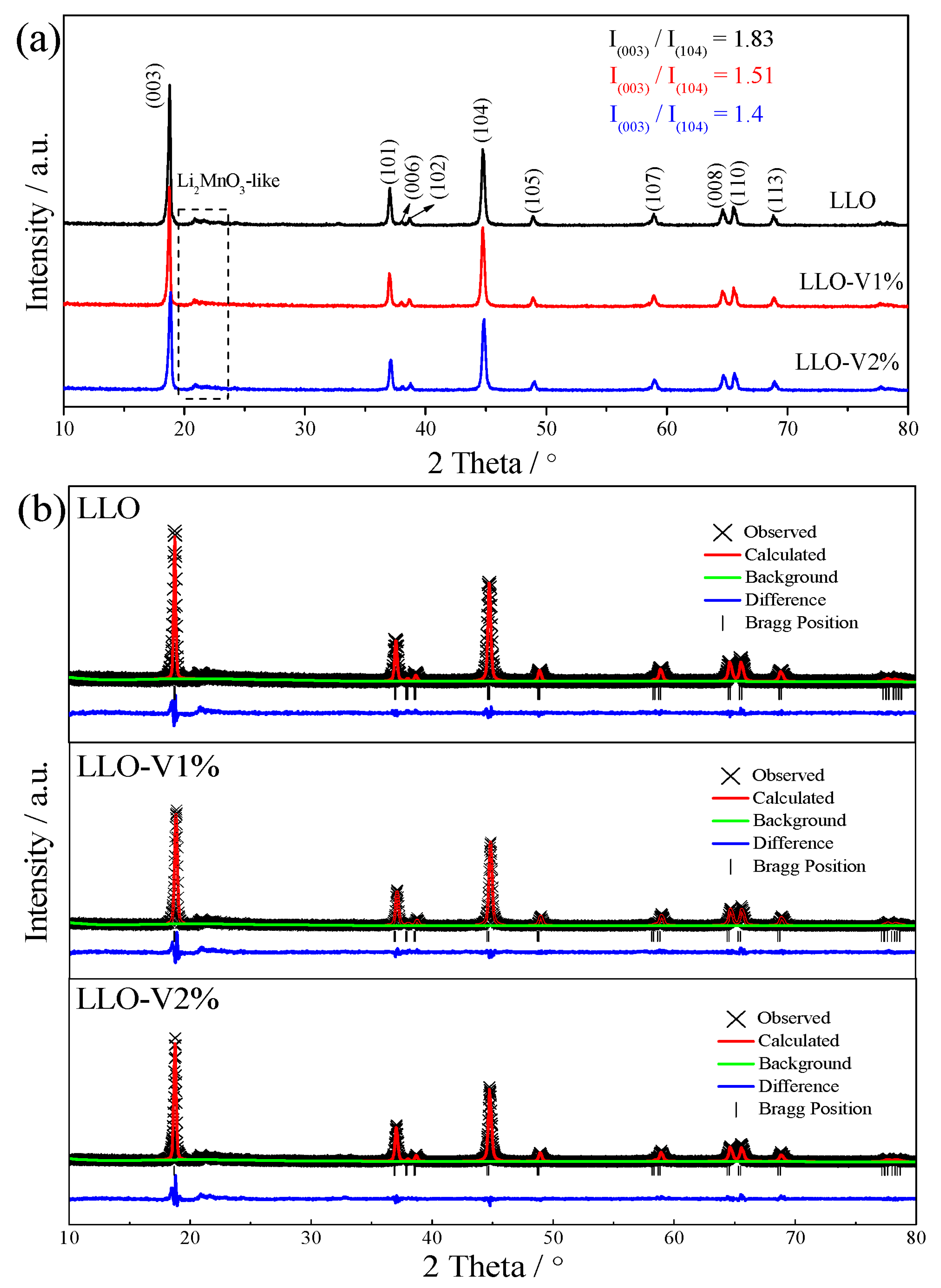
| Sample | a (Å) | c (Å) | c/a | V (Å3) | Rp (%) | Rwp (%) |
|---|---|---|---|---|---|---|
| LLO | 2.8504 | 14.2359 | 4.9944 | 100.17 | 8.08 | 4.14 |
| LLO-V1% | 2.8547 | 14.2570 | 4.9942 | 100.62 | 8.69 | 5.30 |
| LLO-V2% | 2.8581 | 14.2721 | 4.9936 | 100.96 | 9.21 | 6.23 |
| Sample | Initial Charging Capacity (mAh g−1) | Initial Discharge Capacity (mAh g−1) | Initial Coulomb Efficiency (%) | Capacity Retention (%) |
|---|---|---|---|---|
| LLO | 380.5 | 290.8 | 76.4 | 74.5 |
| LLO-V1% | 339.8 | 272.2 | 80.1 | 86 |
| LLO-V2% | 313.7 | 256 | 81.6 | 77.3 |
| Sample | Rs/ohm | Rct/ohm | DLi+/cm2 s−1 |
|---|---|---|---|
| LLO | 2.7 | 34.8 | 5.19 × 10⁻¹¹ |
| LLO-V1% | 1.5 | 26.4 | 7.08 × 10⁻¹¹ |
| LLO-140cycles | 2.3 | 16.1 | 1.45 × 10⁻¹¹ |
| LLO-V1%-140cycles | 2.2 | 14.1 | 3.44 × 10⁻¹¹ |
Disclaimer/Publisher’s Note: The statements, opinions and data contained in all publications are solely those of the individual author(s) and contributor(s) and not of MDPI and/or the editor(s). MDPI and/or the editor(s) disclaim responsibility for any injury to people or property resulting from any ideas, methods, instructions or products referred to in the content. |
© 2025 by the authors. Licensee MDPI, Basel, Switzerland. This article is an open access article distributed under the terms and conditions of the Creative Commons Attribution (CC BY) license (https://creativecommons.org/licenses/by/4.0/).
Share and Cite
Yuan, S.; Ren, C.; Liu, Z.; Chen, Y.; Wang, W. Enhancing the Performance of LLO Through Vanadium Doping and Abundant Exposed (010) Planes in Secondary Particles. Nanomaterials 2025, 15, 1017. https://doi.org/10.3390/nano15131017
Yuan S, Ren C, Liu Z, Chen Y, Wang W. Enhancing the Performance of LLO Through Vanadium Doping and Abundant Exposed (010) Planes in Secondary Particles. Nanomaterials. 2025; 15(13):1017. https://doi.org/10.3390/nano15131017
Chicago/Turabian StyleYuan, Shenghua, Chengwen Ren, Ziwei Liu, Yu Chen, and Wenhui Wang. 2025. "Enhancing the Performance of LLO Through Vanadium Doping and Abundant Exposed (010) Planes in Secondary Particles" Nanomaterials 15, no. 13: 1017. https://doi.org/10.3390/nano15131017
APA StyleYuan, S., Ren, C., Liu, Z., Chen, Y., & Wang, W. (2025). Enhancing the Performance of LLO Through Vanadium Doping and Abundant Exposed (010) Planes in Secondary Particles. Nanomaterials, 15(13), 1017. https://doi.org/10.3390/nano15131017