
3D NiCoW Metallic Compound Nano-Network Structure Catalytic Material for Urea Oxidation

Abstract
1. Introduction
2. Experimental
2.1. Materials
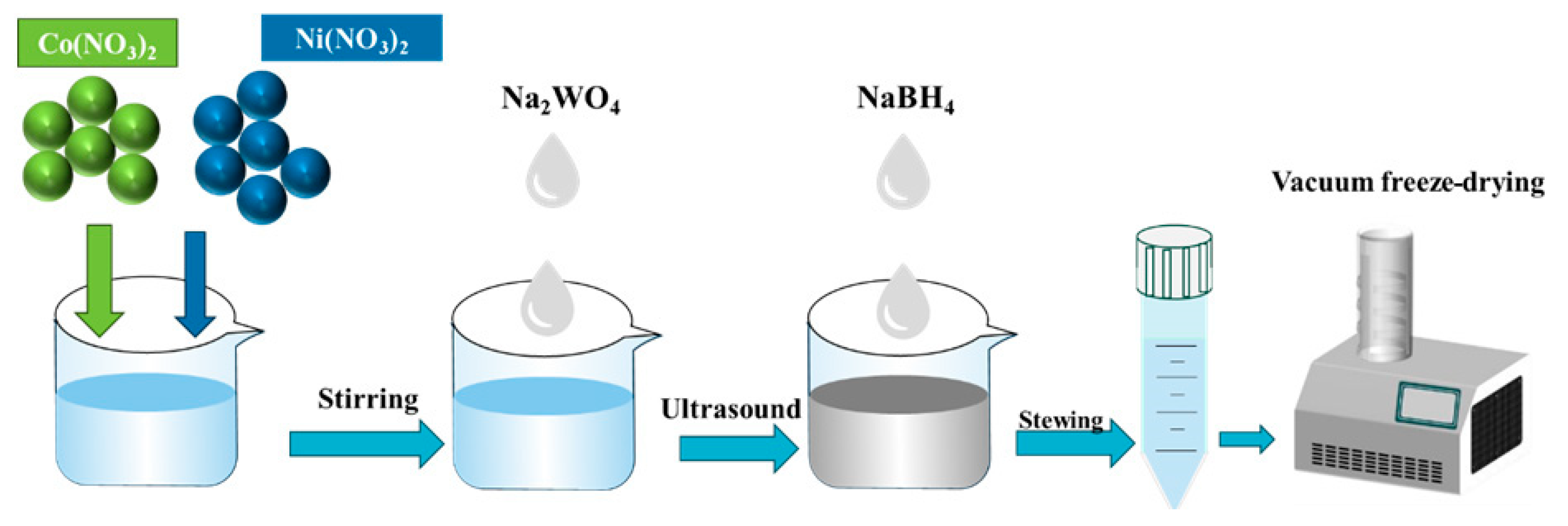
2.2. Preparation of NiCoW and NiCo Catalyst
2.3. Material Characterization
2.4. Electrode Preparation and Electrochemical Measurements
3. Results and Discussion
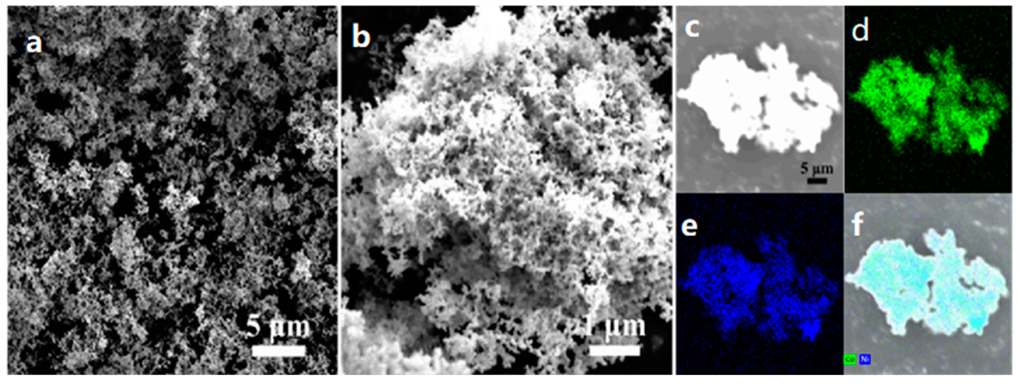
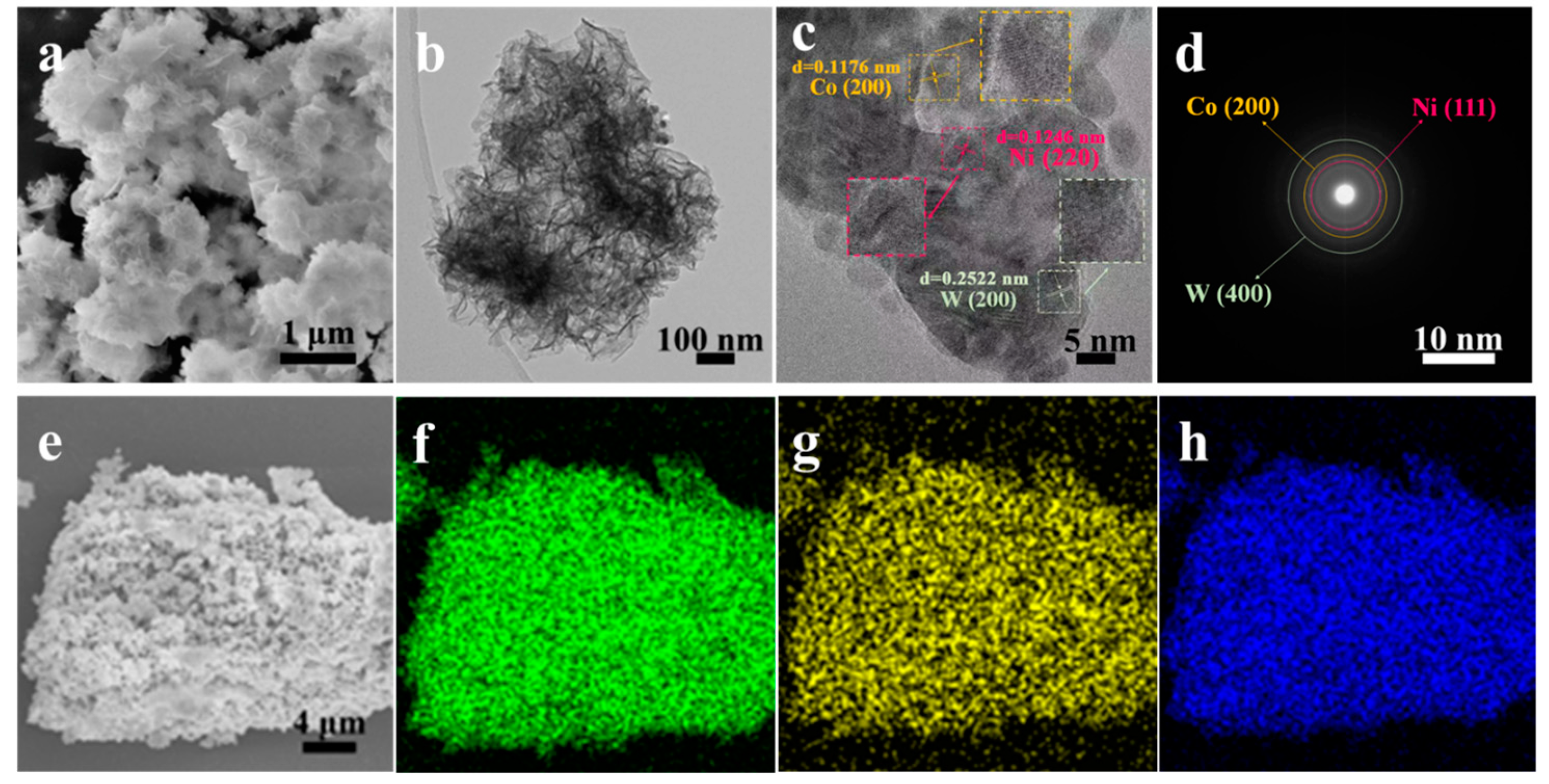
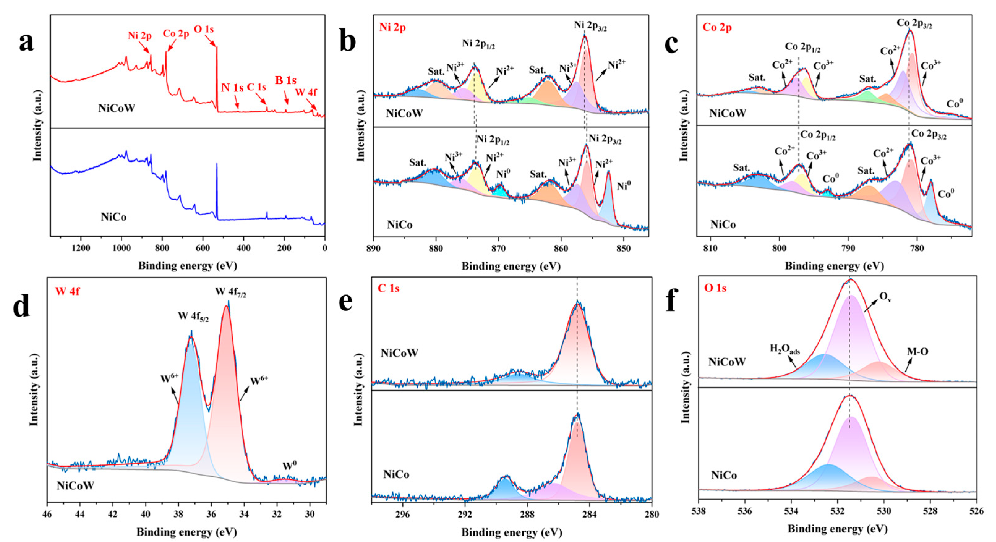
3.1. Characterization of Morphology and Structure
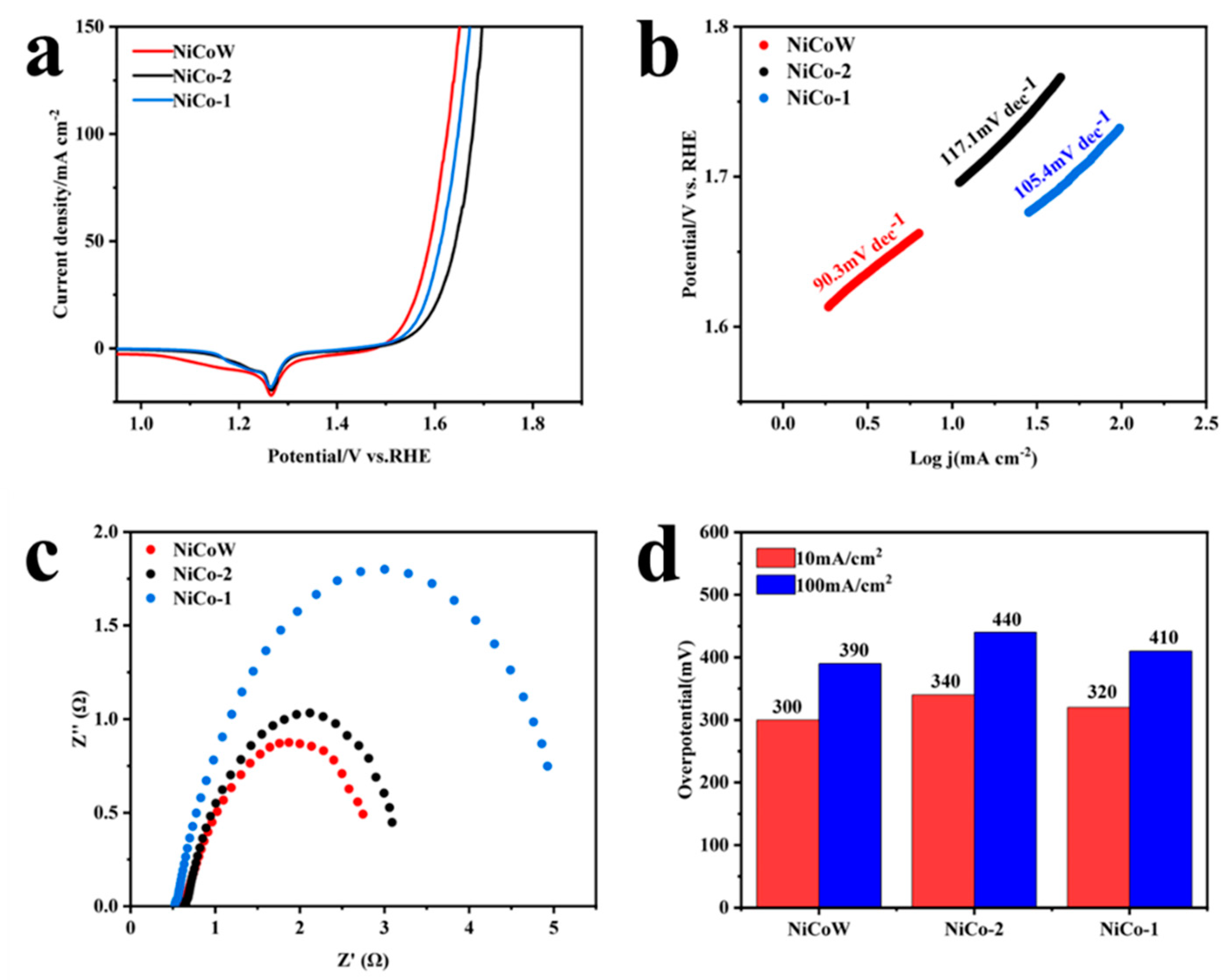
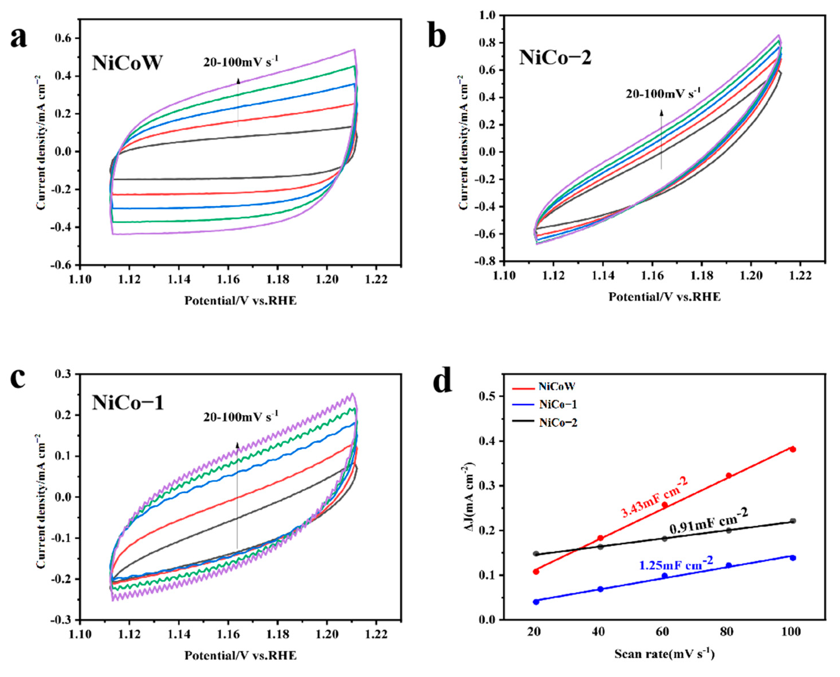
3.2. OER Performance
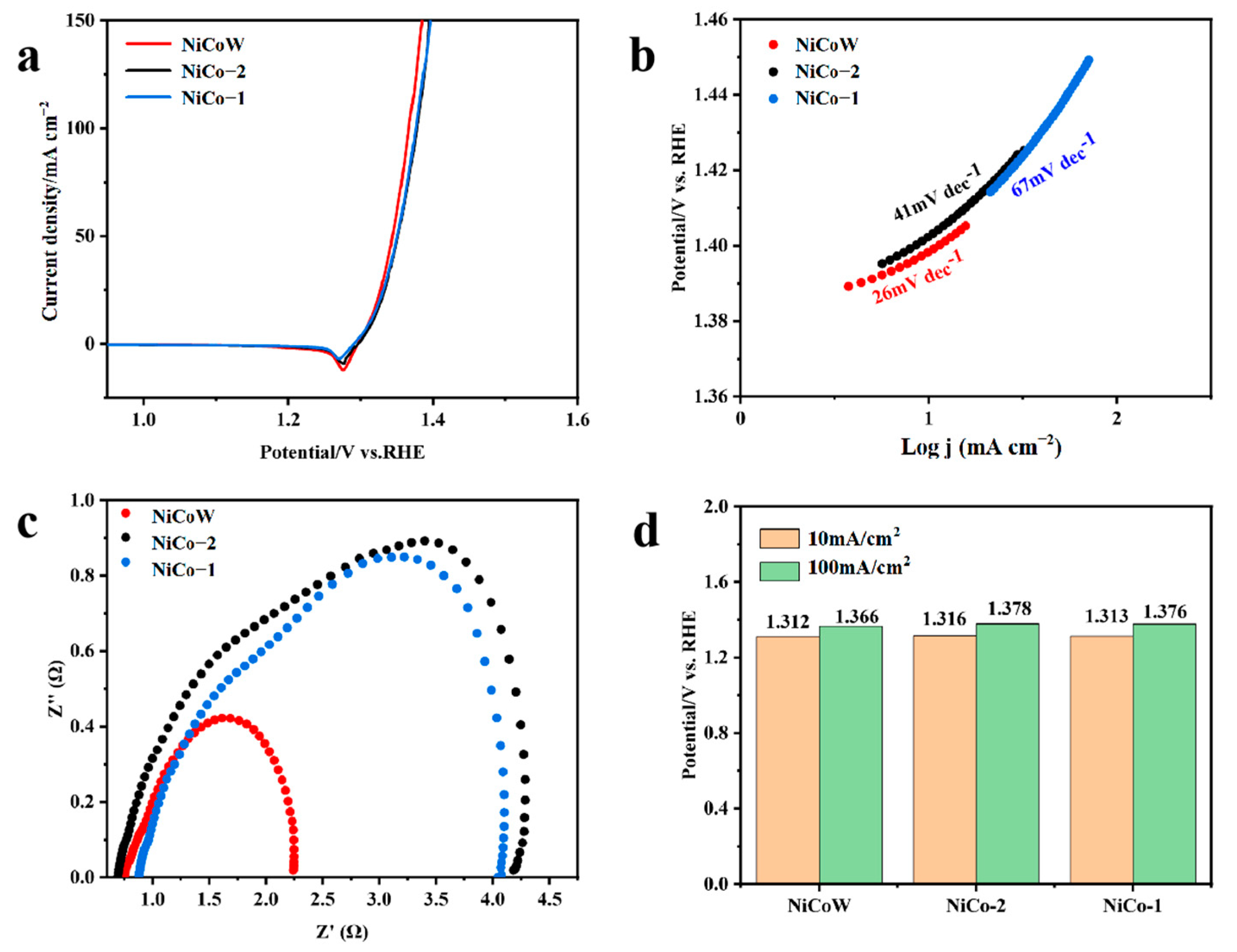
3.3. UOR Performance
3.4. Stability Analysis and Urea-Assisted Overall Water Splitting
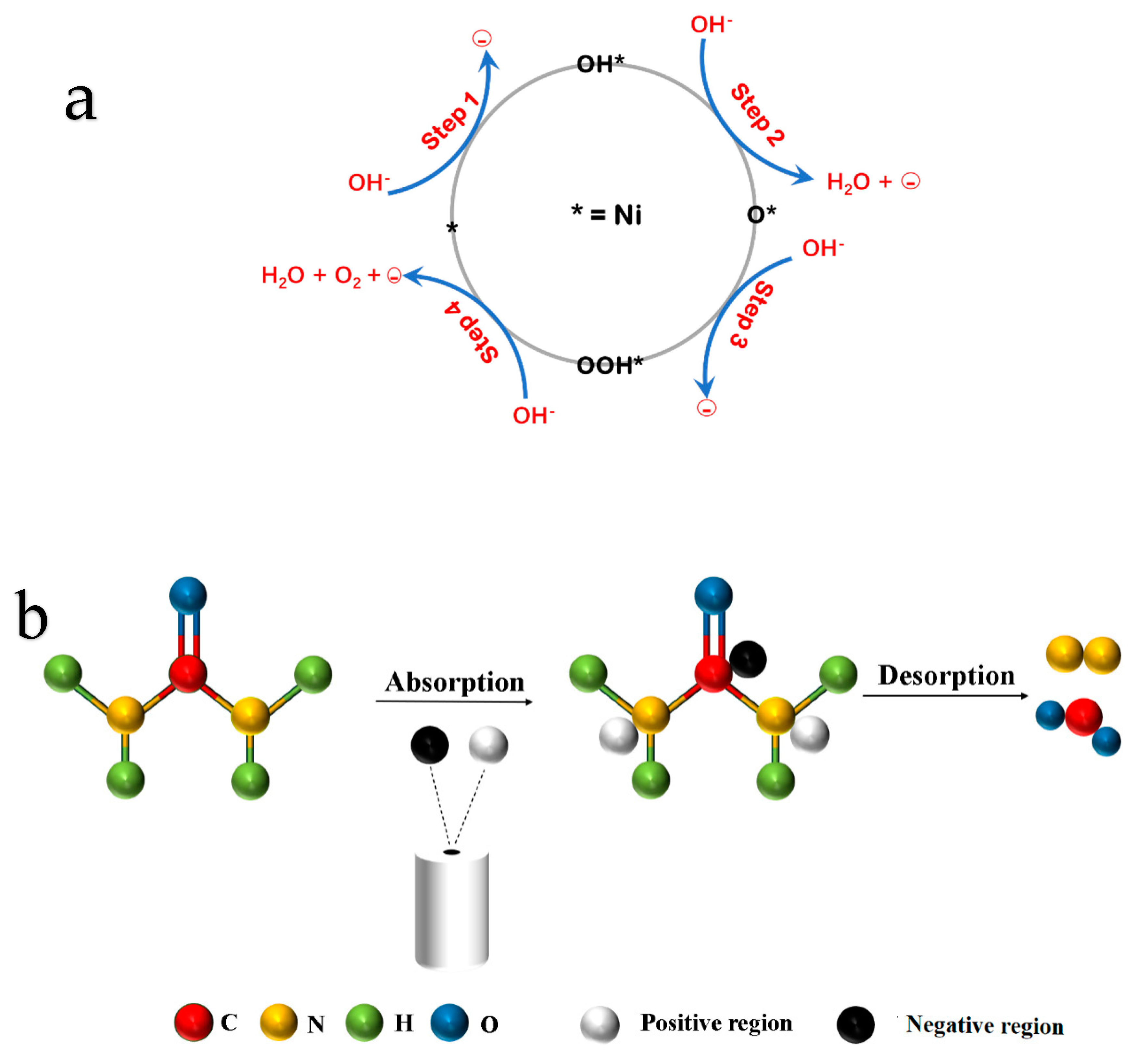
3.5. OER and UOR Mechanism
4. Conclusions
Author Contributions
Funding
Data Availability Statement
Conflicts of Interest
References
- Tian, X.; Zhao, P.; Sheng, W. Hydrogen Evolution and Oxidation: Mechanistic Studies and Material Advances. Adv. Mater. 2019, 31, 1808066. [Google Scholar] [CrossRef] [PubMed]
- Ghosh, S.; Kadam, S.R.; Kolatkar, S.; Neyman, A.; Singh, C.; Enyashin, A.N.; Bar-Ziv, R.; Bar-Sadan, M. W Doping in Ni12P5 as a Platform to Enhance Overall Electrochemical Water Splitting. Acs Appl. Mater. Interfaces 2022, 14, 581–589. [Google Scholar] [CrossRef] [PubMed]
- Wang, Y.; Wang, R.; Duan, S. Optimization Methods of Tungsten Oxide-Based Nanostructures as Electrocatalysts for Water Splitting. Nanomaterials 2023, 13, 1727. [Google Scholar] [CrossRef] [PubMed]
- Wei, T.; Bie, J.; Wei, W.; Chen, S.; Xu, X.; Fa, W.; Wu, X. High-density electron transfer in Ni-metal-organic framework@FeNi-layered double hydroxide for efficient electrocatalytic oxygen evolution. J. Colloid Interface Sci. 2023, 642, 505–512. [Google Scholar] [CrossRef]
- Yang, L.; Zhou, L.; Wang, M.; Qi, Y.; Guo, D.; Li, H.; Chen, X.a.; Wang, S. Transition Metal-Based Electrocatalysts for Seawater Oxidation. Adv. Mater. Interfaces 2022, 9, 2201486. [Google Scholar] [CrossRef]
- Paygozar, S.; Aghdam, A.S.R.; Hassanizadeh, E.; Andaveh, R.; Darband, G.B. Recent progress in non-noble metal-based electrocatalysts for urea-assisted electrochemical hydrogen production. Int. J. Hydrogen Energy 2023, 48, 7219–7259. [Google Scholar] [CrossRef]
- Ji, X.; Zhang, Y.; Ma, Z.; Qiu, Y. Oxygen Vacancy-rich Ni/NiO@NC Nanosheets with Schottky Heterointerface for Efficient Urea Oxidation Reaction. Chemsuschem 2020, 13, 5004–5014. [Google Scholar] [CrossRef]
- Li, J.; Li, J.; Gong, M.; Peng, C.; Wang, H.; Yang, X. Catalyst Design and Progresses for Urea Oxidation Electrolysis in Alkaline Media. Top. Catal. 2021, 64, 532–558. [Google Scholar] [CrossRef]
- Yan, W. Nickel-based Catalysts for Urea Electro-oxidation. Electrochim. Acta 2014, 134, 266–271. [Google Scholar] [CrossRef]
- Akther, J.; Song, C.; Fatih, K.; Pickup, P.G. Electrochemical Production of Ammonia and Urea from Coreduction of Nitrite and Carbon Dioxide at Iron Phthalocyanine Electrodes and Comparison of Analytical Methods. J. Electrochem. Soc. 2023, 170, 026505. [Google Scholar] [CrossRef]
- Sreekanth, T.V.M.; Prasad, K.; Yoo, J.; Kim, J.; Yoo, K. CuWO4 as a cost-effective electrocatalyst for urea oxidation reaction. Inorg. Chem. Commun. 2023, 154, 110933. [Google Scholar] [CrossRef]
- Diao, Y.; Liu, Y.; Hu, G.; Zhao, Y.; Qian, Y.; Wang, H.; Shi, Y.; Li, Z. NiFe nanosheets as urea oxidation reaction electrocatalysts for urea removal and energy-saving hydrogen production. Biosens. Bioelectron. 2022, 211, 114380. [Google Scholar] [CrossRef] [PubMed]
- Yang, K.; Hao, L.; Hou, Y.; Zhang, J.; Yang, J.-H. Summary and application of Ni-based catalysts for electrocatalytic urea oxidation. Int. J. Hydrog. Energy 2024, 51, 966–981. [Google Scholar] [CrossRef]
- Xiao, X.; Zhang, G.; Wang, J.; Wang, X.; Pang, H. Ultrathin One-Dimensional Ni-MIL-77 Nanobelts for High-Performance Electrocatalytic Urea Evolution. Cryst. Growth Des. 2021, 21, 3639–3644. [Google Scholar] [CrossRef]
- Zhang, J.; Song, X.; Kang, L.; Zhu, J.; Liu, L.; Zhang, Q.; Brett, D.J.L.; Shearing, P.R.; Mai, L.; Parkin, I.P.; et al. Stabilizing efficient structures of superwetting electrocatalysts for enhanced urea oxidation reactions. Chem Catal. 2022, 2, 3254–3270. [Google Scholar] [CrossRef]
- Wan, K.; Xiang, Z.; Liu, W.; Wei, H.; Fu, Z.; Liang, Z. Recent progress of transition metal sulfides as electrocatalysts for hydrogen/oxygen evolution reactions. Chin. Sci. Bull.-Chin. 2022, 67, 2126–2141. [Google Scholar] [CrossRef]
- Yin, X.; Zhu, K.; Ye, K.; Yan, J.; Cao, D.; Zhang, D.; Yao, J.; Wang, G. FeNi supported on carbon sponge for efficient urea oxidation in direct urea fuel cell. J. Colloid Interface Sci. 2023, 654, 36–45. [Google Scholar] [CrossRef]
- Hu, X.; Zhu, J.; Li, J.; Wu, Q. Urea electrooxidation: Current development and understanding of Ni-based catalysts. Chemelectrochem 2020, 7, 3211–3228. [Google Scholar] [CrossRef]
- Boggs, B.K.; King, R.L.; Botte, G.G. Urea electrolysis: Direct hydrogen production from urine. Chem. Commun. 2009, 32, 4859–4861. [Google Scholar] [CrossRef]
- Sun, H.; Liu, J.; Kim, H.; Song, S.; Fei, L.; Hu, Z.; Lin, H.J.; Chen, C.T.; Ciucci, F.; Jung, W. Ni-Doped CuO Nanoarrays Activate Urea Adsorption and Stabilizes Reaction Intermediates to Achieve High-Performance Urea Oxidation Catalysts. Adv. Sci. 2022, 9, 2204800. [Google Scholar] [CrossRef]
- Gao, X.; Bai, X.; Wang, P.; Jiao, Y.; Davey, K.; Zheng, Y.; Qiao, S.-Z. Boosting urea electrooxidation on oxyanion-engineered nickel sites via inhibited water oxidation. Nat. Commun. 2023, 14, 5842. [Google Scholar] [CrossRef] [PubMed]
- Chen, Z.-W.; Bai, R.; Annamalai, P.; Badsara, S.S.; Lee, C.-F. The journey of C-S bond formation from metal catalysis to electrocatalysis. New J. Chem. 2021, 46, 15–38. [Google Scholar] [CrossRef]
- Carey, S.J.; Zhao, W.; Campbell, C.T. Bond Energies of Adsorbed Intermediates to Metal Surfaces: Correlation with Hydrogen-Ligand and Hydrogen-Surface Bond Energies and Electronegativities. Angew. Chem.-Int. Ed. 2018, 57, 16877–16881. [Google Scholar] [CrossRef] [PubMed]
- Wei, L.; Du, M.; Zhao, R.; Lv, F.; Li, L.; Zhang, L.; Zhou, D.; Su, J. High-valence Mo doping for highly promoted water oxidation of NiFe (oxy)hydroxide. J. Mater. Chem. A 2022, 10, 23790–23798. [Google Scholar] [CrossRef]
- Xu, J.; Zhao, Z.; Wei, W.; Chang, G.; Xie, Z.; Guo, W.; Liu, D.; Qu, D.; Tang, H.; Li, J. Tuning the Intrinsic Activity and Electrochemical Surface Area of MoS2 via Tiny Zn Doping: Toward an Efficient Hydrogen Evolution Reaction (HER) Catalyst. Chem.—A Eur. J. 2021, 27, 15992–15999. [Google Scholar] [CrossRef]
- Li, H.; Zhang, C.; Xiang, W.; Amin, M.A.; Na, J.; Wang, S.; Yu, J.; Yamauchi, Y. Efficient electrocatalysis for oxygen evolution: W-doped NiFe nanosheets with oxygen vacancies constructed by facile electrodeposition and corrosion. Chem. Eng. J. 2023, 452, 139104. [Google Scholar] [CrossRef]
- Wang, X.; Chen, Y.; Yu, B.; Wang, Z.; Wang, H.; Sun, B.; Li, W.; Yang, D.; Zhang, W. Hierarchically Porous W-Doped CoP Nanoflake Arrays as Highly Efficient and Stable Electrocatalyst for pH-Universal Hydrogen Evolution. Small 2019, 15, 1902613. [Google Scholar] [CrossRef]
- Qin, X.; Ding, H. Preparation of Ni-doped ferrous oxalate nanorods electrocatalysts for oxygen evolution reaction. Chem. Phys. Lett. 2023, 837, 141058. [Google Scholar] [CrossRef]
- Kuo, Y.; Behrendt, F.; Lerch, M. Effect of the specific surface area of Li/MgO catalysts in the oxidative coupling of methane. Z. Fur Phys. Chem. -Int. J. Res. Phys. Chem. Chem. Phys. 2007, 221, 1017–1037. [Google Scholar] [CrossRef]
- Liang, X.; Qi, X.; Bai, Z.; Qin, Y. Study on the Effect of Ultrasound on the Property of Perovskite LaNiO_3. J. Combust. Sci. Technol. 2002, 8, 284–287. [Google Scholar]
- Cai, B.; Dianat, A.; Huebner, R.; Liu, W.; Wen, D.; Benad, A.; Sonntag, L.; Gemming, T.; Cuniberti, G.; Eychmueller, A. Multimetallic Hierarchical Aerogels: Shape Engineering of the Building Blocks for Efficient Electrocatalysis. Adv. Mater. 2017, 29, 1605254. [Google Scholar] [CrossRef] [PubMed]
- Ghosh, S.; Bhandary, N.; Basu, S.; Basu, R.N. Synergistic Effects of Polypyrrole Nanofibers and Pd Nanoparticles for Improved Electrocatalytic Performance of Pd/PPy Nanocomposites for Ethanol Oxidation. Electrocatalysis 2017, 8, 329–339. [Google Scholar] [CrossRef]
- Liu, Z.; Zhang, Z.; Fu, L.; Wang, M.; Zhou, J. Inorganic crystal-supported precious metal single-atom catalysts for photo/ electrocatalysis. Nano Energy 2024, 128, 109869. [Google Scholar] [CrossRef]
- Figueira, F.; Paz, F.A.A. Porphyrin MOF-Derived Porous Carbons: Preparation and Applications. C-J. Carbon Res. 2021, 7, 47. [Google Scholar] [CrossRef]
- Wan, J.; Wu, Z.; Fang, G.; Xian, J.; Dai, J.; Guo, J.; Li, Q.; You, Y.; Liu, K.; Yu, H.; et al. Microwave-assisted exploration of the electron configuration-dependent electrocatalytic urea oxidation activity of 2D porous NiCo2O4 spinel. J. Energy Chem. 2024, 91, 226–235. [Google Scholar] [CrossRef]
- Kiguchi, M.; Iizumi, K.; Saiki, K.; Koma, A. Atomic and electronic structures of heteroepitaxial C60 film grown on Ni(111), Cu(111). Appl. Surf. Sci. 2003, 212, 101–104. [Google Scholar] [CrossRef]
- Wang, L.; Lv, W.; Yang, Y.; Yang, M.; Yang, W.; Tao, H.; Wang, Z.; Xiao, X.; Dong, X. One-step hydrothermal synthesis of nanowire-like W/Mo-Ni3S2/NF electrocatalysts for highly efficient hydrogen evolution reactions. J. Alloys Compd. 2024, 995, 174754. [Google Scholar] [CrossRef]
- Jadhav, H.S.; Lim, A.C.; Roy, A.; Seo, J.G. Room-Temperature Ultrafast Synthesis of NiCo-Layered Double Hydroxide as an Excellent Electrocatalyst for Water Oxidation. Chemistryselect 2019, 4, 2409–2415. [Google Scholar] [CrossRef]
- Rajpure, M.M.; Bandal, H.A.; Jadhav, H.S.; Kim, H. Systematic development of bimetallic MOF and its phosphide derivative as an efficient multifunctional electrocatalyst for urea-assisted water splitting in alkaline medium. J. Electroanal. Chem. 2022, 923, 116825. [Google Scholar] [CrossRef]
- Xiao, H.; Wang, W.; Zhao, M.; Fu, Z.; Bai, M.; Zhang, L.; Zhang, J.; Luo, E.; Zhang, J.; Wu, H.; et al. Insights into synergetic modulation of nickel sites over graphene by introducing tungsten and light for efficient methanol electrooxidation. Chem. Eng. J. 2024, 490, 151415. [Google Scholar] [CrossRef]
- Chen, J.; He, W.; Guo, Y.; Xiao, Y.; Tan, X.; Cui, H.; Wang, C. In situ formed nickel tungsten oxide amorphous layer on metal-organic framework derived ZnxNi1_xWO4 surface by self-reconstruction for acid hydrogen evolution reaction. J. Colloid Interface Sci. 2023, 652, 1347–1355. [Google Scholar] [CrossRef] [PubMed]
- Spataru, T.; Somacescu, S.; Osiceanu, P.; Culita, D.C.; Mihai, M.A.; Florea, M.; Kuncser, A.; Spataru, N. Nickel Species-Modified Mesoporous SnO2 as a Non-Platinum Electrocatalyst for Bioethanol Anodic Oxidation. J. Electrochem. Soc. 2023, 170, 124518. [Google Scholar] [CrossRef]
- Liang, X.; Dong, F.; Tang, Z.; Wang, Q. The Pt/g-C3N4-CNS catalyst via in situ synthesis process with excellent performance for methanol electrocatalytic oxidation reaction. New J. Chem. 2022, 46, 3121–3129. [Google Scholar] [CrossRef]
- Khan, S.; Ali, T.; Wang, X.; Iqbal, W.; Bashir, T.; Chao, W.; Sun, H.; Lu, H.; Yan, C.; Irfan, R.M. Ni3S2@Ni5P4 nanosheets as highly productive catalyst for electrocatalytic oxygen evolution. Chem. Eng. Sci. 2022, 247, 117020. [Google Scholar] [CrossRef]
- Ullah, I.; Munir, A.; Muhammad, S.; Ali, S.; Khalid, N.; Zubair, M.; Sirajuddin, M.; Hussain, S.Z.; Ahmed, S.; Khan, Y.; et al. Influence of W-doping on the optical and electrical properties of SnO2 towards photocatalytic detoxification and electrocatalytic water splitting. J. Alloys Compd. 2020, 827, 154247. [Google Scholar] [CrossRef]
- Guo, F.; Cheng, D.; Chen, Q.; Liu, H.; Wu, Z.; Han, N.; Ni, B.-J.; Chen, Z. Amorphous electrocatalysts for urea oxidation reaction. Prog. Nat. Sci. -Mater. Int. 2024, 34, 362–375. [Google Scholar] [CrossRef]
- Ilyas, T.; Raziq, F.; Ali, S.; Zada, A.; Ilyas, N.; Shaha, R.; Wang, Y.; Qiao, L. Facile synthesis of MoS2/Cu as trifunctional catalyst for electrochemical overall water splitting and photocatalytic CO2 conversion. Mater. Des. 2021, 204, 109674. [Google Scholar] [CrossRef]
- Wu, T.-H.; Lin, Y.-C.; Hou, B.-W.; Liang, W.-Y. Nanostructured β-NiS Catalyst for Enhanced and Stable Electro-oxidation of Urea. Catalysts 2020, 10, 1280. [Google Scholar] [CrossRef]
- Zheng, S.; Cao, X.; Jiao, L. Research progress in the design of electrocatalytic urea oxidation reaction catalysts. J. Shanghai University. Nat. Sci. Ed. 2023, 29, 886–899. [Google Scholar]
- Ge, W.; Lin, L.; Wang, S.-Q.; Wang, Y.; Ma, X.; An, Q.; Zhao, L. Electrocatalytic urea oxidation: Advances in mechanistic insights, nanocatalyst design, and applications. J. Mater. Chem. A 2023, 11, 15100–15121. [Google Scholar] [CrossRef]
- Protsenko, V.S. Thermodynamic aspects of urea oxidation reaction in the context of hydrogen production by electrolysis. Int. J. Hydrogen Energy 2023, 48, 24207–24211. [Google Scholar] [CrossRef]


| HER | Electrocatalysts | Electrolytes | Overpotential at 10 mA cm−2 (mV) | Overpotential at 50 mA cm−2 (mV) |
| Pt/C | 1 M KOH | 40 | 74 | |
| RuO2 | 1 M KOH | 89 | 150 | |
| UOR | Electrocatalysts | Electrolytes | Potential at 10 mA cm−2 (V) | Potential at 50 mA cm−2 (V) |
| Pt/C | 1 M KOH + 0.5 M urea | 1.37 | 1.44 | |
| RuO2 | 1 M KOH + 0.5 M urea | 1.41 | 1.43 |
| Name | Atomic% | |
|---|---|---|
| NiCo-2 | Ni2p | 8.48 |
| Co2p | 25.55 | |
| C1s | 18.41 | |
| O1s | 47.57 | |
| NiCoW | Ni2p | 7.56 |
| Co2p | 13.10 | |
| W4f | 0.85 | |
| C1s | 12.17 | |
| O1s | 66.32 |
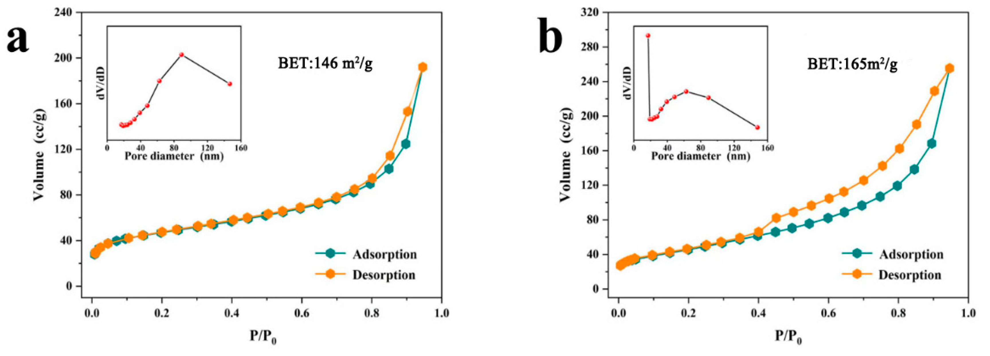
| Catalyst | BJH Pore Size (nm) | BJH Pore Volume (cm3/g) | BET (m2/g) |
|---|---|---|---|
| NiCo-2 | 89.0 | 0.249 | 145.5 |
| NiCoW | 17.1 | 0.395 | 165.1 |
Disclaimer/Publisher’s Note: The statements, opinions and data contained in all publications are solely those of the individual author(s) and contributor(s) and not of MDPI and/or the editor(s). MDPI and/or the editor(s) disclaim responsibility for any injury to people or property resulting from any ideas, methods, instructions or products referred to in the content. |
© 2024 by the authors. Licensee MDPI, Basel, Switzerland. This article is an open access article distributed under the terms and conditions of the Creative Commons Attribution (CC BY) license (https://creativecommons.org/licenses/by/4.0/).
Share and Cite
Liang, Z.; Yao, L.; Zhang, Y.; Li, S.; Xiao, X. 3D NiCoW Metallic Compound Nano-Network Structure Catalytic Material for Urea Oxidation. Nanomaterials 2024, 14, 1793. https://doi.org/10.3390/nano14221793
Liang Z, Yao L, Zhang Y, Li S, Xiao X. 3D NiCoW Metallic Compound Nano-Network Structure Catalytic Material for Urea Oxidation. Nanomaterials. 2024; 14(22):1793. https://doi.org/10.3390/nano14221793
Chicago/Turabian StyleLiang, Zuoyuan, Lang Yao, Yipeng Zhang, Sirong Li, and Xuechun Xiao. 2024. "3D NiCoW Metallic Compound Nano-Network Structure Catalytic Material for Urea Oxidation" Nanomaterials 14, no. 22: 1793. https://doi.org/10.3390/nano14221793
APA StyleLiang, Z., Yao, L., Zhang, Y., Li, S., & Xiao, X. (2024). 3D NiCoW Metallic Compound Nano-Network Structure Catalytic Material for Urea Oxidation. Nanomaterials, 14(22), 1793. https://doi.org/10.3390/nano14221793