Abstract
This paper delves into the development of a group of twisted donor-acceptor-donor (D-A-D) derivatives incorporating bicarbazole as electron donor and benzophenone as electron acceptor for potential use as blue emitters in OLEDs. The derivatives were synthesized in a reaction of 4,4′-difluorobenzophenone with various 9-alkyl-9′H-3,3′-bicarbazoles. The materials, namely, DB14, DB23, and DB29, were designed with different alkyl side chains to enhance their solubility and film-forming properties of layers formed using the spin-coating from solution method. The new materials demonstrate high thermal stabilities with decomposition temperatures >383 °C, glass transition temperatures in the range of 95–145 °C, high blue photoluminescence quantum yields (>52%), and short decay times, which range in nanoseconds. Due to their characteristics, the derivatives were used as blue emitters in OLED devices. Some of the OLEDs incorporating the DB23 emitter demonstrated a high external quantum efficiency (EQEmax) of 5.3%, which is very similar to the theoretical limit of the first-generation devices.
1. Introduction
Organic light-emitting diodes (OLEDs) have ushered in a technological revolution with their remarkable impact on diverse sectors of our daily lives. These versatile devices, known for their outstanding display and lighting capabilities, have become indispensable components in different technologies including smartphones, tablets, televisions, and automotive applications [1,2,3,4,5,6]. OLEDs are steadily advancing in terms of their performance, longevity, and production processes [7,8,9]. To provide displays and energy-efficient lighting solutions, blue OLEDs are an essential technological component. Despite their significance, the development of blue OLEDs has posed persistent challenges owing to the inherent instability of blue-emitting materials [10,11,12]. Recent research efforts have resulted in notable progress in the domain of promising host derivatives for the blue devices, offering promising avenues to overcome the efficiency limitations and reaching high internal quantum efficiency [13,14,15,16]. Simultaneously, scientists and engineers have made noteworthy strides in the creation of novel organic emitters tailored for blue OLEDs [17,18,19]. These emitters were engineered to deliver high efficiency, exceptional color purity, and a narrow emission bandwidth, addressing the demands of modern OLED technology [20,21,22,23].
OLED technologies have been generally divided into three generations, depending on the characteristics of the used emitting material, which determines the properties of the diode. First-generation devices use fluorescent emitters [24], second-generation devices use phosphorescent emitters, and third-generation OLEDs are from materials which has a thermally activated delayed fluorescence (TADF) effect. Upon electrical excitation, only 25% of formed excitons in first-generation fluorescent OLEDs are singlet and emissive. The other 75% are of triplet multiplicity and are not involved in light emission [25,26]. Recently, we published carbazole-diphenyl sulfone-carbazole (D-A-D) bipolar blue light emitting materials for first-generation OLEDs. One device outperformed others by showing a peak external quantum efficiency (EQEmax) of 4.0% for deep-blue emission (CIEy = 0.09) [27].
In this research article, we present a group of twisted D-A-D compounds incorporating bicarbazole and benzophenone fragments that have also been developed for potential use as blue-emitting layers for the OLEDs. These derivatives include 4,4′-bis(9′-butyl-[3,3′]-bicarbazol-9-yl)benzophenone (DB14), 4,4′-bis(9′-{2-ethylhexyl}-[3,3′]- bicarbazol-9-yl)benzophenone (DB23), and 4,4′-bis(9′-octyl-[3,3′]-bicarbazol-9-yl)benzophenone (DB29). The compounds were designed with different alkyl side chains, which determine the film-forming and solubility properties of the blue emitters. Some of the OLED devices based on the bicarbazole and benzophenone fragments containing D-A-D emitters demonstrated promising performance as compared with the carbazole-diphenyl sulfone-carbazole-based emitters. Specifically, one device, producing a greenish-blue emission with a CIEy coordinate of (0.22, 0.22), exhibited an EQEmax of 5.3%, which is very similar to the theoretical limit of the first-generation devices [10].
2. Experimental Section
2.1. Instruments
Thermogravimetric analysis (TGA) of all compounds was carried out using a TGAQ50 instrument (Verder Scientific Haan, Haan, Germany). Both TGA and differential scanning calorimetry (DSC) profiles were recorded under a nitrogen atmosphere at a controlled heating rate of 10 °C/min. For differential scanning calorimetry (DSC), measurements were carried out on Bruker Reflex II thermos-system (Bruker, Berlin, Germany). UV–visible spectroscopy was carried out using an HP-8453 diode array spectrometer (Agilent Technology Inc., Hachioji, Tokyo, Japan) to capture the absorption spectra of the compounds. Moreover, the Tauc plot was generated using the absorbance wavelength data. Photoluminescence (PL) spectra were captured utilizing the Aminco-Bowman Series 2 luminescence spectrometer (Agilent Technology Inc., Hachioji, Tokyo, Japan). For low-temperature PL (LTPL), a Hitachi F-7000 fluorescence spectrophotometer (Hitachi High-Tech, Tokyo, Japan) was employed. The LTPL measurements were performed at a temperature of 77 K to ascertain the singlet energy of the compounds. Cyclic voltammetry (CV) experiments were conducted using the CH instrument CH1604A potentiostat (Annatech Co., Ltd., Taipei, Taiwan). Time-resolved photoluminescence measurements were executed using an Edinburgh instrument spectrometer FLS980 (Edinburgh Instruments Ltd., Livingston, UK) to accurately determine the decay time of the compounds.
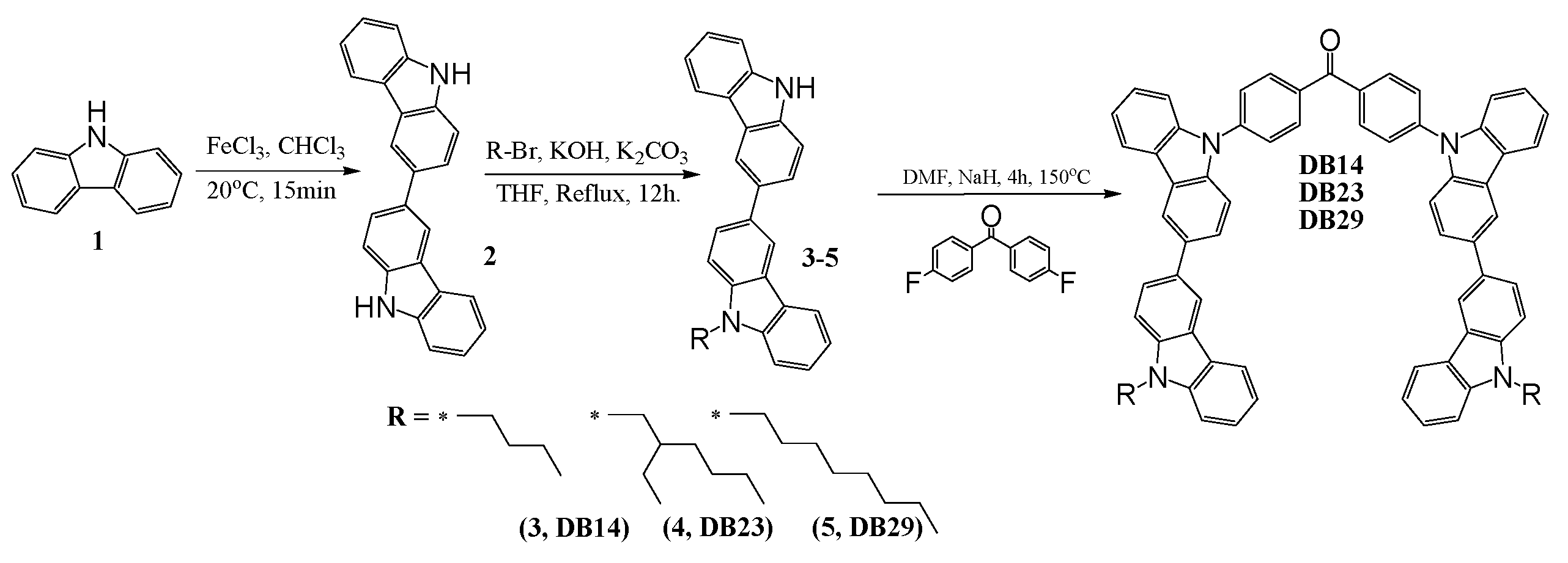
2.2. Synthesis and Structure Characterization of the Materials
Carbazole (1), benzylbromide, bromoethane, 1-bromobutane, 1-bromohexane, 2-ethylhexylbromide, 1-bromooctane, ferric chloride (FeCl3), potassium hydroxide (KOH), K2CO3, NaH, sodium sulphate (Na2SO4), 4,4′-difluorobenzophenone, chloroform, dimethyl formamide (DMF), and tetrahydrofuran (THF) were purchased from Aldrich and used as received.
3,3′-Bicarbazole (2) was prepared by oxidation of carbazole using FeCl3 as it was reported in the literature [28].
9-Butyl-9′H-3,3′-bicarbazole (3): 1-bromobutane (0.82 g, 6.0 mmol) was added to a stirred solution of 3,3′-bicarbazole (2) (2.00 g, 6.0 mmol) in 50 mL of tetrahydrofuran. The reaction mixture was refluxed, and then potassium carbonate (1.66 g, 12.0 mmol) and powdered KOH (2.02 g, 36.1 mmol) were added stepwise. The resulting mixture reacted for 4 h. After TLC test, the inorganic materials were filtered off and the organic derivatives were purified using silica gel column chromatography. A mixture of tetrahydrofuran and hexane (vol. ratio 1:5) was used as an eluent. Yield: 0.96 g (41%) of yellowish material. 1H NMR (400 MHz, CDCl3, δ, m.d.): 8.29 (s, 2H), 8.11–8.06 (m, 2H), 7.73–7.67 (m, 2H), 7.41–7.32 (m, 6H), 7.17 (t, 2H, J = 7.2 Hz), 4.29 (t, 2H, J = 7.2 Hz), 1.79 (quint, 2H, J = 7.2 Hz), 1.38–1.29 (m, 2H), 0.87 (t, 3H, J = 7.2 Hz). 13C NMR (400 MHz, CDCl3, δ, m.d.): 139.64, 138.56, 133.33, 125.94, 125.86, 125.72, 125.57, 124.00, 123.61, 123.43, 123.08, 120.51, 120.46, 119,51, 119.03, 119.00, 118.92, 118.82, 110.83, 110.77, 108.95, 108.86, 42.99, 31.25, 20.65, 13.97. MS (APCI+, 20 V): 339.10 ([M + H], 100%).
9-(2-Ethylhexyl)-9′H-3,3′-bicarbazole (4) was prepared by a similar method which was published earlier [27].
9-Octyl-9′H-3,3′-bicarbazole (5): 1-Bromooctane (1.16 g, 6.0 mmol) was added to a stirred solution of 3,3′-bicarbazole (2) (2.00 g, 6.0 mmol) in 50 mL of tetrahydrofuran. The mixture was heated to reflux, and then potassium carbonate (1.66 g, 12.0 mmol) and powdered KOH (2.02 g, 36.2 mmol) were added stepwise. The resulting mixture reacted for 4 h. After TLC test, the inorganic compounds were filtered off and the organic materials were separated using silica gel column chromatography. A mixture of tetrahydrofuran and hexane (vol. ratio 1:7) was an eluent. Yield: 1.15 g (43%) of yellowish material. 1H NMR (400 MHz, CDCl3, δ, m.d.): 8.45 (d, 2H, J = 8.0 Hz), 8.25–8.20 (m, 2H), 8.04 (s, 1H), 7.87 (d, 1H, J = 8.0 Hz), 7.83 (dd, 1H, J1 = 8.4 Hz, J2 = 1.6 Hz), 7.56–7.50 (m, 3H), 7.48 (d, 3H, J = 7.2 Hz), 7.31 (t, 2H, J = 8.0 Hz), 4.37 (t, 2H, J = 7.0 Hz), 1.95 (qu, 2H, J = 7.3 Hz), 1.48–1.30 (m, 10H), 0.92 (t, 3H, J = 7.0 Hz). 13C NMR (400 MHz, CDCl3, δ, m.d.): 140.94, 140.02, 139.62, 138.53, 133.30, 125.94, 125.85, 125.70, 125.56, 124.00, 123.61, 123.42, 123.08, 120.49, 120.45, 120.40, 119.51, 119.00, 118.92, 118.79, 110.80, 110.74, 108.92, 108.83, 43.25, 31.85, 29.45, 29.23, 29.08, 27.39, 22.65, 14.12. MS (APCI+, 20 V): 444.67 ([M + H], 100%).
4,4′-Bis(9′-butyl-[3,3′]-bicarbazol-9-yl)benzophenone (DB14): 9-Butyl-9′H-3,3′-bicarbazole (3) (0.40 g, 1.0 mmol) and NaH (0.10 g, 4.1 mmol) were stirred in 6 mL of DMF at room temperature under nitrogen for 20 min. Then, 4,4′-difluorobenzophenone (0.11 g, 0.5 mmol) was added to the reaction, and the resulting mixture was stirred at 150 °C under nitrogen for 4 h. After TLC control, the reaction mixture was cooled and quenched by the addition of ice water. The product was extracted using chloroform. The combined extract was dried over anhydrous Na2SO4. The crude product was purified using silica gel column chromatography using the mixture of THF and hexane (vol. ratio 1:3) as an eluent. Yield: 0.38 g (77%) of yellow amorphous material. Tg = 145 °C (DSC). 1H NMR (400 MHz, CDCl3, δ, m.d.): 8.51–8.41 (m, 4H), 8.30–8.23 (m, 6H), 7.91–7.83 (m, 8H), 7.71 (d, 2H, J = 8.4 Hz), 7.65 (d, 2H, J = 8.4 Hz), 7.57–7.38 (m, 10H), 7.32–7.29 (m, 4H), 4.42–4.36 (m, 4H), 1.98–1.91 (m, 4H), 1.51–1.45 (m, 4H), 1.01 (t, 6H, J = 7.4 Hz). MS (APCI+, 20 V): 954.8 ([M + H], 100%).
4,4′-Bis(9′-{2-ethylhexyl}-[3,3′]-bicarbazol-9-yl)benzophenone (DB23): 9-[2-Ethylhexyl]-9′H-3,3′-bicarbazole (4) (0.40 g, 0.9 mmol) and NaH (0.10 g, 4.1 mmol) were stirred in 6 mL of DMF at room temperature under nitrogen for 20 min. Then, 4,4‘-difluorobenzophenone (0.10 g, 0.5 mmol) was added to the reaction, and the resulting mixture was stirred at 150 °C under nitrogen for 4 h. After TLC control, the reaction mixture was cooled and quenched by the addition of ice water. The product was extracted using chloroform. The combined extract was dried over anhydrous Na2SO4. The crude product was purified using silica gel column chromatography using the mixture of THF and hexane (vol. ratio 1:5) as an eluent. Yield: 0.40 g (83%) of yellow amorphous material. Tg = 104 °C (DSC). 1H NMR (400 MHz, CDCl3-, δ, m.d.): 8.51–8.45 (m, 4H), 8.31–8.22 (m, 6H), 7.91–7.79 (m, 8H), 7.76–7.70 (m, 4H), 7.66–7.36 (m, 14H), 4.27–4.23 (m, 4H), 1.90–1.87 (m, 2H), 1.47–1.29 (m, 16H), 1.00–0.90 (m, 12H). 13C NMR (400 MHz, CDCl3, δ, m.d.): 195.67, 141.42, 140.70, 140.22, 135.79, 132.79, 131.96, 129.44, 128.17, 127.18, 126.36, 126.13, 125.75, 125.49, 125.45, 124.56, 124.19, 123.42, 122.98, 120.77, 120.41, 119.02, 118.92, 118.82, 118.77, 110.08, 109.95, 109.27, 109.13, 47.57, 39.50, 31.06, 28.89, 24.45, 23.10, 14.09, 10.96. MS (APCI+, 20 V): 1066.55 ([M + H], 100%).
4,4′-Bis(9′-octyl-[3,3′]-bicarbazol-9-yl)benzophenone (DB29): 9-Octyl-9′H-3,3′-bicarbazole (5) (0.40 g, 0.9 mmol) and NaH (0.10 g, 4.1 mmol) were stirred in 6 mL of DMF at room temperature under nitrogen for 20 min. Then, 4,4‘-difluorobenzophenone (0.10 g, 0.5 mmol) was added to the reaction and the resulting mixture was stirred at 150 °C under nitrogen for 4 h. After TLC control, the reaction mixture was cooled and quenched by the addition of ice water. The product was extracted using chloroform. The combined extract was dried over anhydrous Na2SO4. The crude product was purified using silica gel column chromatography using the mixture of THF and hexane (vol. ratio 1:5) as an eluent. Yield: 0.44 g (92%) of yellow amorphous material. Tg = 95 °C (DSC). 1H NMR (400 MHz, CDCl3-, δ, m.d.): 8.50 (dd, 4H, J1 = 15.2 Hz, J2 = 1.6 Hz), 8.30 (d, 2H, J = 7.6 Hz), 8.27–8.24 (m, 6H), 7.91–7.86 (m, 8H), 7.71 (d, 2H, J = 8.4 Hz), 7.66 (d, 2H, J = 8.0 Hz), 7.56–7.47 (m, 8H), 7.42 (t, 2H, J = 7.2 Hz), 7.33–7.29 (m, 2H), 4.38 (t, 4H, J = 7.2 Hz), 1.99–1.92 (m, 4H), 1.48–1.30 (m, 20H), 0.92 (t, 6H, J = 6.6 Hz). 13C NMR (400 MHz, CDCl3, δ, m.d.): 194.51, 142.04, 140.96, 140.71, 139.74, 139.28, 135.78, 135.41, 132.84, 131.97, 126.38, 126.34, 126.15, 125.79, 125.49, 124.57, 124.20, 123.48, 123.03, 120.78, 120.66, 120.50, 119.02, 118.85, 110.09, 109.97, 109.00, 108.87, 43.26, 31.85, 29.45, 29.23, 29.08, 27.39, 22.65, 14.12. MS (APCI+, 20 V): 1067.78 ([M + H], 100%).
2.3. Device Fabrication
OLED devices were fabricated utilizing a pre-sputtered ITO glass substrate. The substrate underwent a thorough cleaning process, including 30 min treatments with acetone and isopropyl alcohol (IPA) at elevated temperatures of 50 and 60 °C. Subsequently, the substrates were transferred to a UV chamber that was preheated, and exposed to UV light for 10 min. The deposition of layers occurred within a glove box, maintaining an inert atmosphere. The hole injection layer (PEDOT:PSS) was spin-coated onto the substrates for 20 s at 4000 rpm, followed by a 10 min heating step at 130 °C. Subsequently, the cooled substrates were subjected to a 20-s spin-coating process at 2500 rpm for the emissive layer. The subsequent stages encompassed the thermal evaporation of the electron-injecting/transporting layer and aluminum cathode within a vacuum of 1.33 × 10⁻⁴ Pa. The substrates remained under vacuum conditions within a mini chamber in the glove box to preserve their quality until individual testing. All testing protocols were executed in a completely dark environment under ambient conditions. The CS-100A luminescence spectrophotometer was employed for recording the current density–voltage–luminance (J-V-L) characteristics, while the PR-655 spectrophotometer was used for power efficacy–luminance–current characteristics. A Keithley voltmeter was utilized to measure the current–voltage (I-V) characteristics. The device area was determined to be 0.09 cm2. The EQE of the devices was computed following the methodology outlined in the relevant literature, meticulously adhering to this approach during the testing and analysis procedures [20].
3. Results and Discussion
A three-step synthetic pathway was employed to synthesize the bicarbazole-based materials, as is demonstrated in Scheme 1.
Scheme 1.
Synthetic pathway of DB14, DB23, and DB29.
3,3′-Bicarbazole (2) was synthesized through the oxidation of 9H-carbazole (1) using iron (III) chloride, as is described in the ESI file. Various 9-alkyl-9′H-3,3′-bicarbazoles (3–5) were prepared via N-alkylation reactions between a bicarbazole and the corresponding alkyl bromides, utilizing potassium hydroxide and potassium carbonate in tetrahydrofuran (THF). The next step involved the nucleophilic aromatic substitution of partially alkylated bicarbazole with 4,4′-difluorobenzophenone. This reaction was conducted in DMF, employing sodium hydride as a base, yielding the desired materials. This multi-step process resulted in the successful synthesis of the targeted bicarbazole-based compounds. The values of glass transition temperatures are influenced by the distinct alkyl chains in the chemical structures of materials DB14, DB23, and DB29. The derivative DB14, characterized by the shortest butyl alkyl chain, exhibited the highest glass transition temperature at 145 °C. The elongation of the alkyl chain led to decreased but still suitable Tg values for device forming, with DB23 and DB29 showing temperatures of 105 °C and 95 °C, respectively, as verified by DSC.
3.1. Material Characteristics
3.1.1. DFT Calculations
Theoretical calculations were carried out to establish a relation between the electrochemical properties and geometries of the synthesized compounds. All calculations were carried out using Gaussian09.0D [29]. The polarizable continuum model, which Gaussian09 uses by default, was employed for the solvent adjustments [30]. In all compounds, HOMO was found to be located over the peripheral carbazole units, while LUMO was found to be spread over the central benzophenone unit. The HOMO/LUMO distributions ensure that the present molecules have donor-acceptor characteristics, in which carbazole units act as donor units and benzophenone acts as an acceptor unit. The values of HOMO/LUMO were theoretically calculated to be −5.39/−2.28, −5.40/−2.28, and −5.40/−2.26 eV for DB14, DB23, and DB29, respectively. Further, the singlet and triplet energies were very crucial for the designed emitters to evaluate their potential for optoelectronic devices; hence, the singlet and triplet energy levels of all synthesized compounds were established through TD-DFT calculations. All compounds showed high triplet energies of about 2.65 eV, which indicated that these molecules have the potential to be used in the emitting layer of OLEDs. The HOMO/LUMO and singlet/triplet energies of DB23 are shown in Figure 1. Similarly, the theoretical results for DB13 and DB29 are presented in Figure S1 of ESI. All theoretical results are also tabulated in Table 1.
Figure 1.
Electron density contours of FMO and theoretically calculated electronic properties of the compound DB23.
Table 1.
Optoelectronic and thermal characteristics of the derivatives DB14, DB23, and DB29.
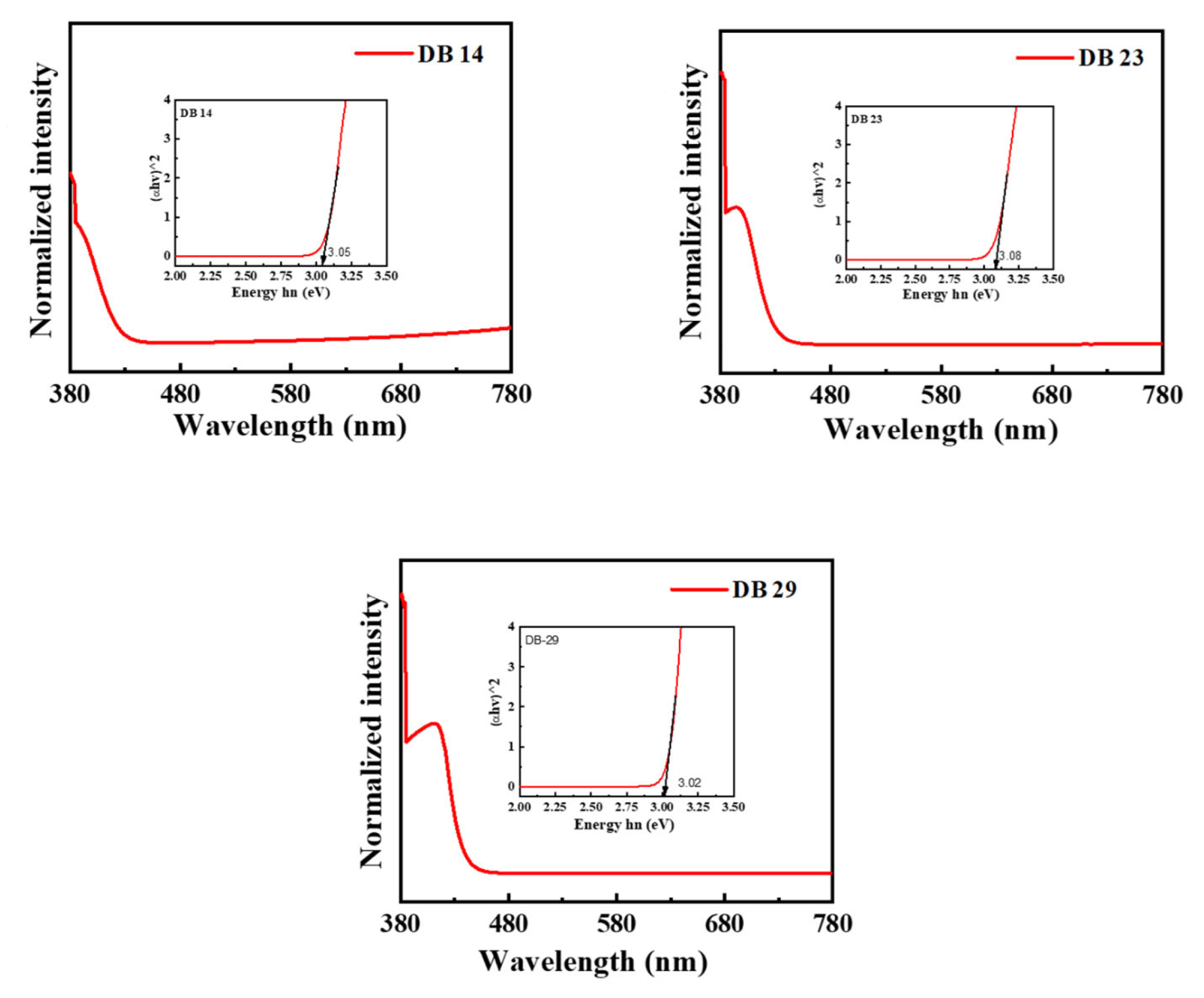
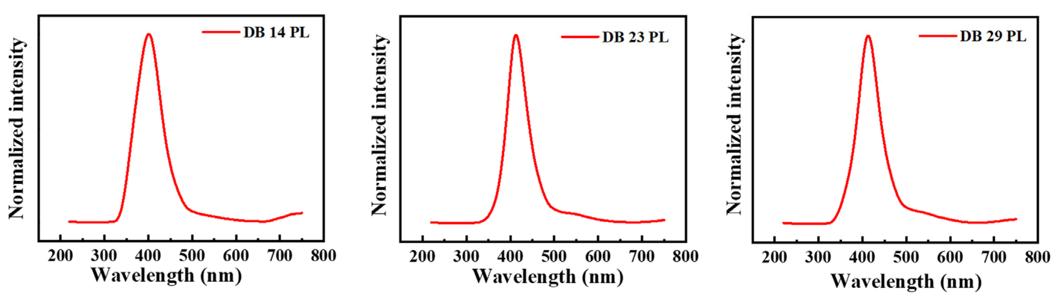
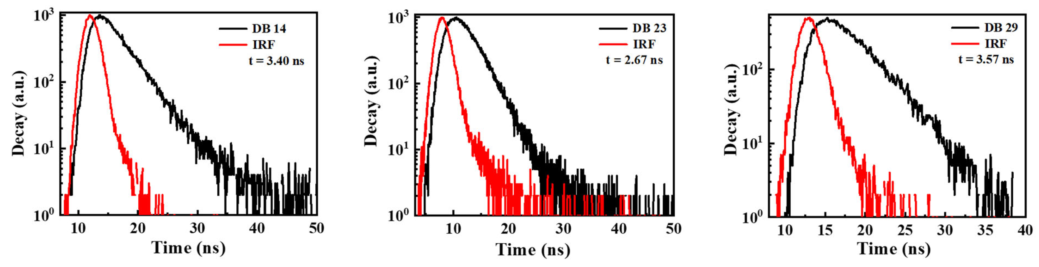
3.1.2. Photophysical Properties
The derivatives DB14, DB23, and DB29 exhibit substantial photoluminescence quantum yields (PLQY) of 55.6, 52.0, and 55.5%, respectively. The PLQY values are summarized in Table 1. The UV-absorption bands of these compounds are demonstrated in Figure 2. The materials were investigated using tetrahydrofuran (THF) solvent under typical conditions. Notably, all compounds displayed primary and secondary absorption peaks consistently at around 375 and 400 nm. The UV absorption wavelength and intensity were also used to construct the Tauc plots for the materials (Figure 2) using the following values: (α × hν)1/2 for the x-axis and hν for the y-axis, where α is the intensity and hν is the energy (hν = 1240/wavelength). The Tauc plots demonstrated the bandgaps of the investigated compounds, which are 3.05 eV for DB14, 3.08 eV for DB23, and 3.02 eV for DB29 (Table 1).
Figure 2.
Ultraviolet-visible absorbance spectra and Tauc plots (inset) of the compounds DB14, DB23, and DB29.
For the measurements of photoluminescence, the maxima absorbance wavelengths were employed as the wavelengths for excitation, which are shown in Table 1. In Figure 3, the photoluminescence (PL) spectra of the derivatives DB14, DB23, and DB29 are depicted. They show very similar emission bands for all compounds with maxima wavelengths of approximately 400 nm due to the similar electronic structure of the derivatives.
Figure 3.
Photoluminescence (PL) spectra of the derivatives DB14, DB23, and DB29.
Moreover, to establish the triplet energies of the potential emitters, photoluminescence (LTPL) spectra at low temperature were also recorded. Notably, the compounds DB14, DB23, and DB29 exhibited elevated triplet energies of 2.83, 2.84, and 2.73 eV, respectively, as visually represented in Figure 4. These specific characteristics are also included in Table 1 for reference.
Figure 4.
LTPL spectra of the derivatives DB14, DB23, and DB29 at 77 K of the compounds.
In Figure 5, the time-resolved photoluminescence (TRPL) analysis illustrates the values of the decay times for the DB14, DB23, and DB29 compounds, which were 3.40, 2.67, and 3.57 ns, respectively. It could be stated that all lifetime curves of the materials demonstrate a nanosecond-scale component. Usually, the decay lifetime of fluorescent emitters ranges in picoseconds. However, our materials demonstrate decay in the nanoscale, also indicating a possible use of triplet energy levels.
Figure 5.
TRPL spectra for the transient decay of the materials DB14, DB23, and DB29. IRF is the instrument response function, which is measured as a control parameter before and after each measurement.
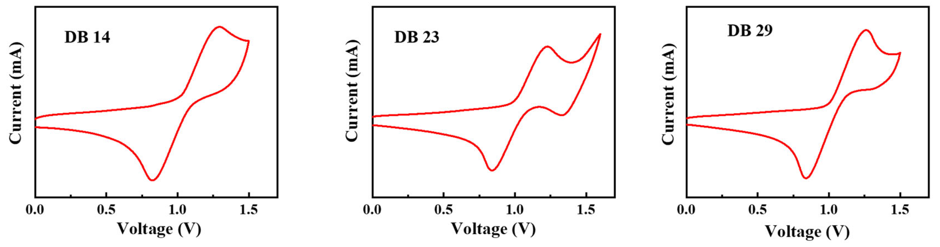
3.1.3. Electrochemical Properties
The electrochemical attributes of the DB14, DB23, and DB29 compounds were assessed through cyclic voltammetry (CV) measurements, which are depicted in Figure 6. By using the obtained oxidation onset values, the HOMO levels were calculated using Equation (1) and the LUMO levels were calculated using Equation (2), according to the method described in the literature [31,32]:
ELUMO = EHOMO + Eg
Figure 6.
Curves of CV scans of the molecules DB14, DB23, and DB29.
The calculated HOMO levels were −5.70, −5.63, and −5.66 eV, while the corresponding LUMO levels were −2.65, −2.55, and −2.64 eV for the DB14, DB23, and DB29 compounds, respectively. These values along with the earlier bandgap measurements are presented in Table 1. It could be stated that the HOMO and LUMO levels of the compounds are found to be suitable for blue-emitting layers using the earlier-mentioned CBP host material.
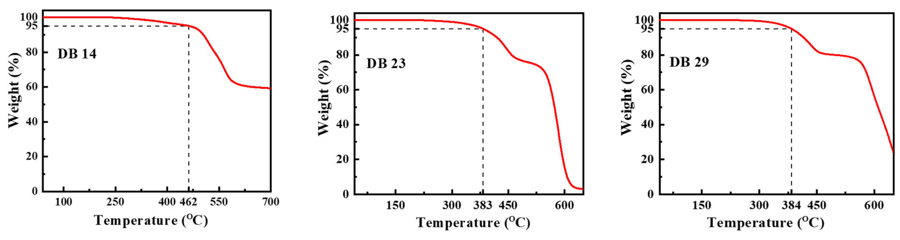
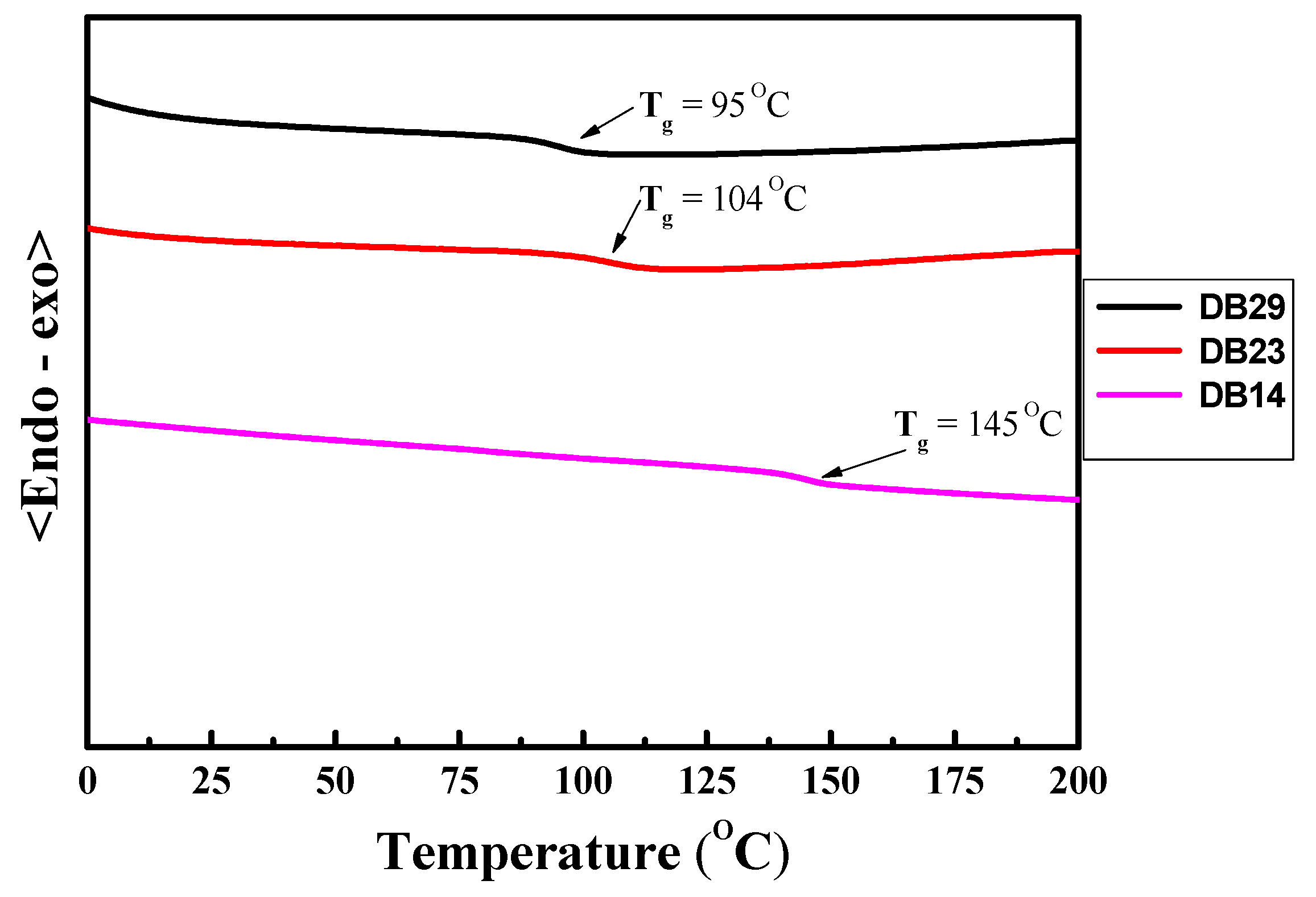
3.1.4. Thermal Properties
The characteristics of thermal stability of the materials DB14, DB23, and DB29 were examined in a nitrogen atmosphere. The curves of the thermogravimetric analysis (TGA) are presented in Figure 7. For DB14, having the shortest alkyl chains, the temperature at which 5% weight loss occurred, i.e., the decomposition temperature (Td), was obtained at 462 °C during heating. The materials DB23 and DB29, featuring lengthier aliphatic substitutions, exhibited a lower thermal stability, with Td values of 383 °C and 384 °C, respectively. These findings demonstrate that the new materials have very good thermal stability as emitting materials for application in OLED devices.
Figure 7.
Curves of the TGA measurements of the materials DB14, DB23, and DB29.
The DSC thermograms of second heating for the DB14, DB23, and DB29 compounds are displayed in Figure 8. Notably, upon analyzing the second heating curves, it becomes evident that the novel derivatives exhibit glass transition temperatures (Tg) that directly correlate with the length of their alkyl substituents. For instance, the DB14 material with the shortest butyl substitution has the highest glass transition temperature of 145 °C. This trend persists also for compounds featuring more extended alkyl groups: the DB23 and DB29 derivatives with 2-ethylhexyl and octyl substitutions, respectively, display glass transition temperatures of 104 °C and 95 °C. Hence, these results indicated that the developed compounds demonstrate a high thermal stability and are suitable for optoelectronic devices. The comprehensive Td and glass transition temperature (Tg) values are compiled in Table 1.
Figure 8.
DSC curves of second heating of the materials DB14, DB23, and DB29.
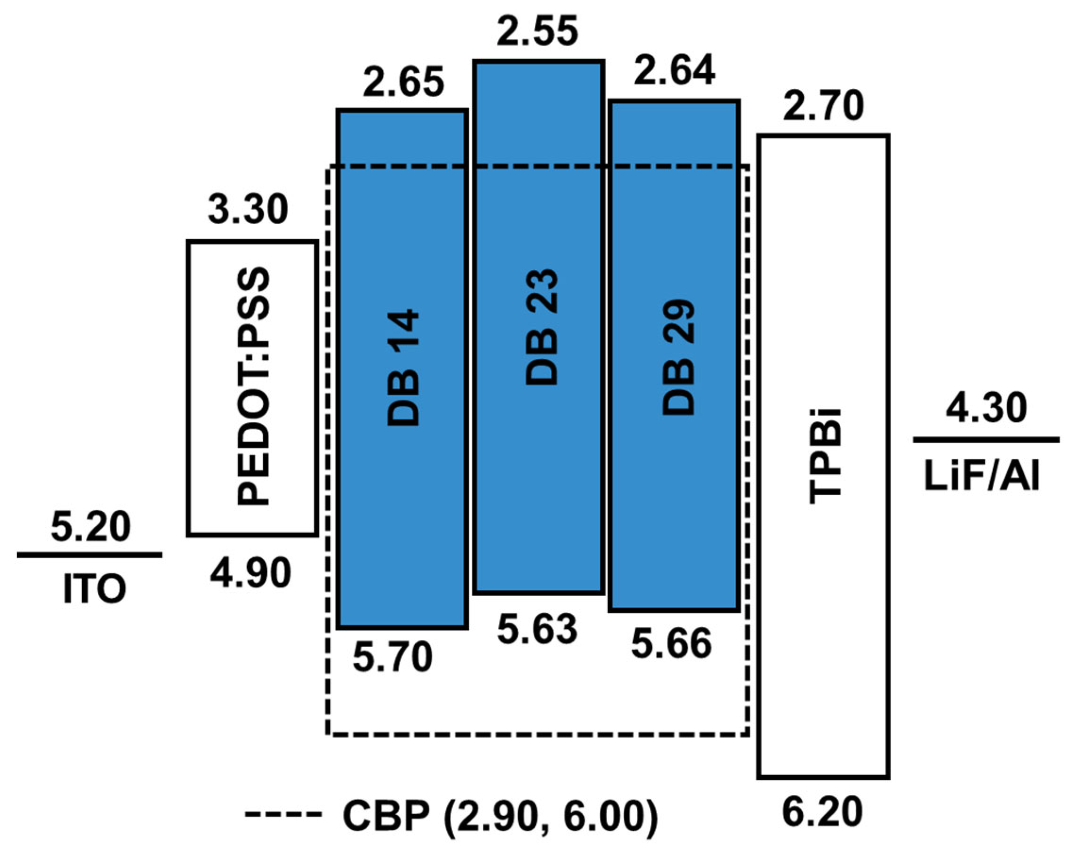
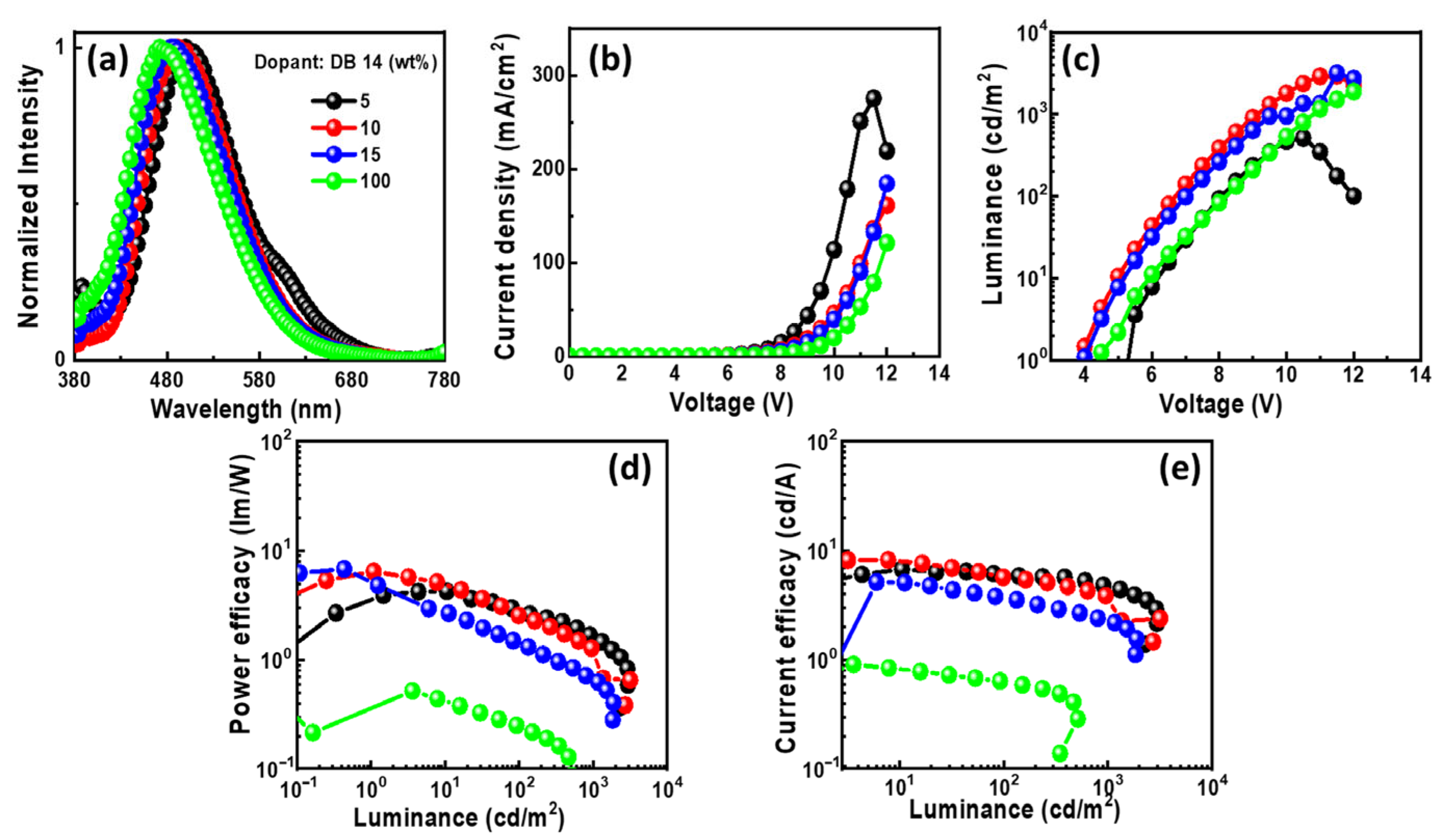
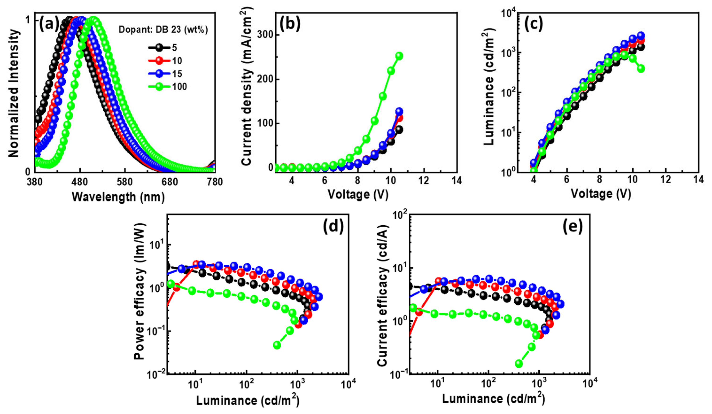
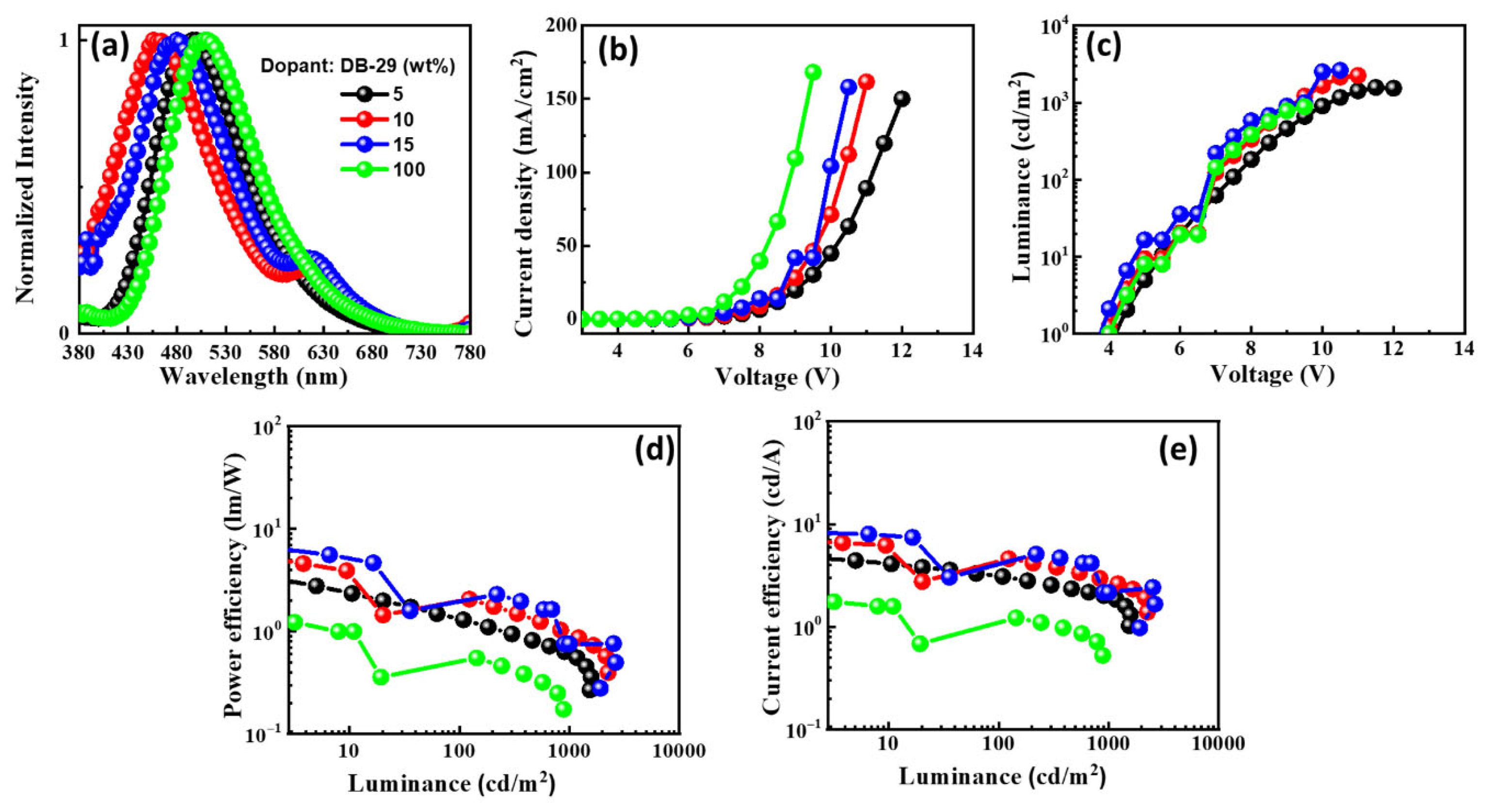
3.1.5. Electroluminescent Properties
The schematic energy level diagram in Figure 9 illustrates the configuration of OLED devices prepared in this study. These devices incorporated the emitters DB14, DB23, and DB29 doped within a CBP host matrix. The device structure comprised ITO/PEDOT:PSS/host CBP: emitter DB14, DB23, or DB29 (5, 10, or 15wt.%)/TPBi/LiF/Al.
Figure 9.
Energy-level diagram of the OLEDs using the emitters DB14, DB23, and DB29 doped in CBP host.
The electroluminescence (EL) properties of the devices using the new emitting materials dispersed within the CBP host are shown in Figure 10, Figure 11 and Figure 12. The corresponding characteristics for each emitter are also detailed in Table 2. Within each figure, various aspects are illustrated: (a) EL spectra, (b) current density–voltage characteristics, (c) luminance–voltage characteristics, (d) power efficacy–luminance characteristics, and € current efficacy–luminance characteristics.
Figure 10.
EL properties of the devices using the emitter DB14 doped in CBP host: (a) EL spectra, (b) current density–voltage, (c) luminance–voltage, (d) power efficacy–luminance, and (e) current efficacy–luminance characteristics.
Figure 11.
The EL properties of the OLEDs using emitting material DB23 doped in CBP host: (a) EL spectra, (b) current density–voltage, (c) luminance–voltage, (d) power efficacy–luminance, and (e) current efficacy–luminance characteristics.
Figure 12.
The EL characteristics of the OLEDs with emitter DB29 doped in CBP host material: (a) EL spectra, (b) current density–voltage, (c) luminance–voltage, (d) power efficacy–luminance, and (e) current efficacy–luminance characteristics.
Table 2.
EL properties of the OLEDs with the emitting materials DB14, DB29, and DB23 doped in CBP host matrix.
In Figure 10a, the EL spectra of the OLEDs with DB14 exhibit peaks around 480 nm, indicating blue emission. The presence of sole peaks implies the successful energy transfer between host and guest. The emission wavelength in the EL of the devices undergoes a shift when compared with the PL spectra of the DB14 emitter, indicating the influence of the CBP host on emission. An evident emission spectrum of the emitter becomes apparent with an increase in the concentration of the DB14 dopant. Notably, both non-doped and doped devices exhibit very similar EL emission peaks. In Figure 10b–e, the current density–luminance–voltage and power efficacy–luminance–current efficacy characteristics are depicted. The non-doped device exhibits a significantly lower efficacy compared to the doped devices, highlighting the substantial role of the host material. Consequently, a device based on a 10 wt% doping concentration surpasses others in terms of power efficacy, showcasing a PEmax of 4.4 lm/W, a CEmax of 7.6 cd/A, an EQEmax of 3.3%, and an Lmax of 3175 cd/m2 at a turn-on voltage of 5.1 V.
In Figure 11a, the EL spectra of the devices with DB23 exhibit single peaks at around 470 nm, indicating blue emission. The presence of single peaks suggests the successful host–guest energy transfer completion. The emission wavelength in the EL of the devices undergoes a shift when compared with the PL spectra of the DB23 emitter, indicating the influence of the CBP host on emission. An evident emission spectrum of the emitter becomes apparent with an increase in the concentration of the DB23 dopant. Notably, both doped and non-doped devices exhibit similar EL emission peaks. Figure 11b–e demonstrate current density–luminance–voltage and power efficacy–luminance–current efficacy characteristics. Comparatively, the non-doped device shows a considerably lower efficacy than the doped devices, demonstrating the crucial role of the host material. The device utilizing a 15 wt% doping concentration of the emitter has a maxima PEmax of 3.2 lm/W, a CEmax of 5.3 cd/A, and an Lmax of 2076 cd/m2 at a voltage of 5.1 V. Additionally, the device having a 10 wt% doping concentration reveals a remarkable EQEmax of 5.3%, even surpassing the theoretical limit for fluorescent emitters. The emitter DB23-based device stands out in comparison to the others.
The EL spectra of the DB29-based device exhibit a blue shift with increasing doping concentration, in contrast to the non-doped device, as can be seen in Figure 12a. The EL spectra maxima change from approximately 490 nm to 430 nm in the region of blue emission. Single peaks of the emissions signify the achievement of complete energy transfer between host and guest. The emission wavelength in the EL of the devices undergoes a shift when compared with the PL spectra of the DB29 emitter, indicating the influence of the CBP host on emission. An evident emission spectrum of the emitter becomes apparent with an increase in the concentration of the DB29 dopant. Figure 12b–e illustrate the current density–luminance–voltage and power efficacy–luminance–current efficacy characteristics. The non-doped device showcases a more favorable current density–voltage characteristic compared to the doped devices, although its efficacy is considerably lower than that of its doped counterparts. Consequently, the role of the host material is pronounced, leading to the prominence of the device with a 15 wt% doping concentration. This device outperforms others in terms of power efficacy, exhibiting a PEmax of 7.9 lm/W, a CEmax of 9.1 cd/A, an EQEmax of 4.0%, and an Lmax of 2631 cd/m2 at a voltage of 4.7 V. Impressively, this device showcases the highest PE and CE values among all.
As depicted in Table 2, the DB23-based device exhibits the highest EQE among all devices, surpassing both previous research and the outcomes of this study. This enhanced performance could be attributed to the inclusion of the branched alkyl side chains in the molecule, which likely contributed to improved molecule solubility for the fabrication of wet-processed OLED devices and the film-forming properties of the material. Nevertheless, the PE and CE of the DB29-based device demonstrated superior performance. This can be attributed to its appropriate HOMO and LUMO levels, which facilitated the efficient host–guest energy transfer. Additionally, the incorporation of two donor moieties of the bicarbazole contributed to a balanced charge transfer, further enhancing its performance.
4. Conclusions
In conclusion, this study presents an exploration of twisted donor-acceptor-donor compounds, specifically bicarbazole-benzophenone-bicarbazole-based compounds, as potential blue emitters for blue OLEDs. The synthesized emitters DB14, DB23, and DB29, were systematically designed with tailored alkyl side chains to enhance their film-forming and solubility properties. The investigation encompassed thorough characterization, including photo-physical analysis to determine photoluminescence quantum yields, UV absorption, and emission characteristics. Electrochemical measurements provided insights into HOMO and LUMO energy levels, while a thermal analysis unveiled the remarkable thermal stability of the compounds. The OLED devices incorporating these emitters demonstrated noteworthy performance, with DB23 exhibiting the highest EQE among all devices, reaching a peak value of 5.3%. The study also highlighted the significant influence of host–guest energy transfer, optimal doping concentrations, and molecular structures on device efficiency. Notably, the research outcomes underscore the considerable potential of the newly developed D-A-D derivatives in advancing OLED technology. This work contributes to the ongoing progress of OLED materials and their applications, offering insights into the design of efficient blue emitters. This research not only contributes to the understanding of advanced OLED materials but also provides insights into designing efficient blue emitters for future display and lighting applications, thereby advancing the field of organic electronics.
Supplementary Materials
The following supporting information can be downloaded at: https://www.mdpi.com/article/10.3390/nano14020146/s1.
Author Contributions
Investigation, D.B., I.S., P.G., M.R.N., D.T., K.K. and G.K.; writing—original draft preparation, D.B., I.S., P.G. and S.B.; writing—review and editing, J.-H.J. and S.G. All authors have read and agreed to the published version of the manuscript.
Funding
This work was supported by the project funded by the Research Council of Lithuania (Grant No. S-MIP-22-84) and by the Ministry of Science and Technology (MOST), Taiwan (Grant No. 109-2923-M-007-003-MY3).
Data Availability Statement
The data presented in this study are available on request from the corresponding authors.
Conflicts of Interest
The authors declare no conflicts of interest.
References
- Sasabe, H.; Kido, J. Development of High Performance OLEDs for General Lighting. J. Mater. Chem. C 2013, 1, 1699–1707. [Google Scholar] [CrossRef]
- Reineke, S.; Lindner, F.; Schwartz, G.; Seidler, N.; Walzer, K.; Lüssem, B.; Leo, K. White Organic Light-Emitting Diodes with Fluorescent Tube Efficiency. Nature 2009, 459, 234–238. [Google Scholar] [CrossRef] [PubMed]
- Park, S.W.; Kim, D.; Rhee, Y.M. Overcoming the Limitation of Spin Statistics in Organic Light Emitting Diodes (OLEDs): Hot Exciton Mechanism and Its Characterization. Int. J. Mol. Sci. 2023, 24, 12362. [Google Scholar] [CrossRef]
- Zhou, Z.; Xie, X.; Sun, Z.; Wang, X.; An, Z.; Huang, W. Recent advances in metal-free phosphorescent materials for organic light-emitting diodes. J. Mater. Chem. C 2023, 11, 3143–3161. [Google Scholar] [CrossRef]
- Chen, Y.-T.; Wen, S.-W.; Liao, P.-H.; Lee, W.-K.; Lee, C.-C.; Huang, C.-W.; Yang, Y.-H.; Lin, K.-C.; Chang, C.-J.; Su, G.-D.; et al. Reflective 3D pixel configuration for enhancing efficiency of OLED displays. Org. Electron. 2022, 103, 106451. [Google Scholar] [CrossRef]
- Huang, Y.; Xu, H.; Ye, Z. Image quality evaluation for OLED-based smart-phone displays at various lighting conditions. Displays 2021, 70, 102115. [Google Scholar] [CrossRef]
- Gupta, N.; Nagar, M.R.; Anamika; Gautam, P.; Maiti, B.; Jou, J.-H.; Kuila, B.K. Triazine and Thiophene-Containing Conjugated Polymer Network Emitter-Based Solution-Processable Stable Blue Organic LEDs. ACS Appl. Polym. Mater. 2022, 5, 130–140. [Google Scholar] [CrossRef]
- Kawamura, Y.; Yanagida, S.; Forrest, S.R. Energy Transfer in Polymer Electrophosphorescent Light Emitting Devices with Single and Multiple Doped Luminescent Layers. J. Appl. Phys. 2002, 92, 87–93. [Google Scholar] [CrossRef]
- Tavgeniene, D.; Krucaite, G.; Baranauskyte, U.; Wu, J.Z.; Su, H.Y.; Huang, C.W.; Chang, C.H.; Grigalevicius, S. Phenanthro[9,10-d]imidazole based new host materials for efficient red phosphorescent OLEDs. Dye. Pigment. 2017, 137, 615–621. [Google Scholar] [CrossRef]
- Lee, J.-H.; Chen, C.-H.; Lee, P.-H.; Lin, H.-Y.; Leung, M.-K.; Chiu, T.-L.; Lin, C.-F. Blue Organic Light-Emitting Diodes: Current Status, Challenges, and Future Outlook. J. Mater. Chem. C 2019, 7, 5874–5888. [Google Scholar] [CrossRef]
- Peng, F.; Zhong, W.; He, J.; Zhong, Z.; Guo, T.; Ying, L. Effect of Alkyl Side Chain Length on the Electroluminescent Performance of Blue Light-Emitting Poly(Fluorene-Co-Dibenzothiophene-S,S-Dioxide). Dye. Pigment. 2021, 187, 109139. [Google Scholar] [CrossRef]
- Jiang, J.; Lee, J.Y. Degradation mechanisms and lifetime extending strategy of phosphorescent and thermally activated delayed-fluorescence organic light-emitting diodes. Mater. Today 2023, 68, 204–233. [Google Scholar] [CrossRef]
- Bommireddy, P.R.B.; Musalikunta, C.S.; Lee, Y.-W.; Suh, Y.; Godumala, M.; Park, S.-H. Recent Endeavors and Perspectives in Developing Solution-Processable Host Materials for Thermally Activated Delayed Fluorescence Organic Light-Emitting Diodes. J. Mater. Chem. C 2023, 11, 13603–13624. [Google Scholar] [CrossRef]
- Chatterjee, T.; Wong, K. Perspective on host materials for thermally activated delayed fluorescence organic light emitting diodes. Adv. Opt. Mater. 2019, 7, 1800565. [Google Scholar] [CrossRef]
- Li, N.; Fang, Y.; Li, L.; Zhao, H.; Quan, Y.; Ye, S.; Fan, Q.; Huang, W. A universal solution-processable bipolar host based on triphenylamine and pyridine for efficient phosphorescent and thermally activated delayed fluorescence OLEDs. J. Lumin. 2018, 199, 465–474. [Google Scholar] [CrossRef]
- Ahn, D.H.; Moon, J.S.; Kim, S.W.; Lee, S.Y.; Karthik, D.; Lee, J.Y.; Kwon, J.H. Effect of various host characteristics on blue thermally activated delayed fluorescent devices. Org. Electron. 2018, 59, 39–44. [Google Scholar] [CrossRef]
- Gu, J.; Shi, W.; Zheng, H.; Chen, G.; Wei, B.; Wong, W.-Y. The Novel Organic Emitters for High-Performance Narrow-Band Deep Blue OLEDs. Top. Curr. Chem. 2023, 381, 26. [Google Scholar] [CrossRef]
- Wu, S.; Aonuma, M.; Zhang, Q.; Huang, S.; Nakagawa, T.; Kuwabara, K.; Adachi, C. High-efficiency deep-blue organic light-emitting diodes based on a thermally activated delayed fluorescence emitter. J. Mater. Chem. C 2014, 2, 421–424. [Google Scholar] [CrossRef]
- Huang, B.; Ban, X.; Sun, K.; Ma, Z.; Mei, Y.; Jiang, W.; Lin, B.; Sun, Y. Thermally activated delayed fluorescence materials based on benzophenone derivative as emitter for efficient solution-processed non-doped green OLED. Dye. Pigment. 2016, 133, 380–386. [Google Scholar] [CrossRef]
- Krucaite, G.; Grigalevicius, S. A review on low-molar-mass carbazole- based derivatives for organic light emitting diodes. Synth. Met. 2019, 247, 90–108. [Google Scholar] [CrossRef]
- Teng, J.-M.; Wang, Y.-F.; Chen, C.-F. Recent progress of narrowband TADF emitters and their applications in OLEDs. J. Mater. Chem. C 2020, 8, 11340–11353. [Google Scholar] [CrossRef]
- Bas, E.E.; Ulukan, P.; Monari, A.; Aviyente, V.; Catak, S. Photophysical Properties of Benzophenone-Based TADF Emitters in Relation to Their Molecular Structure. J. Phys. Chem. A 2022, 126, 473–484. [Google Scholar] [CrossRef] [PubMed]
- Bui, T.-T.; Goubard, F.; Ibrahim-Ouali, M.; Gigmes, D.; Dumur, F. Recent advances on organic blue thermally activated delayed fluorescence (TADF) emitters for organic light-emitting diodes (OLEDs). Beilstein J. Org. Chem. 2018, 14, 282–308. [Google Scholar] [CrossRef] [PubMed]
- Lee, S.Y.; Yasuda, T.; Yang, Y.S.; Zhang, Q.; Adachi, C. Luminous Butterflies: Efficient Exciton Harvesting by Benzophenone Derivatives for Full-Color Delayed Fluorescence OLEDs. Angew. Chem. Int. Ed. 2014, 53, 6402–6406. [Google Scholar] [CrossRef] [PubMed]
- Salehi, A.; Fu, X.; Shin, D.; So, F. Recent Advances in OLED Optical Design. Adv. Funct. Mater. 2019, 29, 1808803. [Google Scholar] [CrossRef]
- Li, L.; Zhu, X.; Sun, S.; Zhang, C.; Yang, B.; Liu, S.; Liu, Z. Blue Organic Light Emitting Diode Materials based on Different Light-emitting Groups. Curr. Org. Chem. 2023, 27, 352–362. [Google Scholar] [CrossRef]
- Gautam, P.; Shahnawaz; Siddiqui, I.; Blazevicius, D.; Krucaite, G.; Tavgeniene, D.; Jou, J.H.; Grigalevicius, S. Bifunctional Bi-carbazole-Benzophenone-Based Twisted Donor–Acceptor–Donor Derivatives for Deep-Blue and Green OLEDs. Nanomaterials 2023, 13, 1408. [Google Scholar] [CrossRef]
- Vaitkeviciene, V.; Grigalevicius, S.; Grazulevicius, J.; Jankauskas, V.; Syromyatnikov, V. Hole-transporting [3,3′]bicarbazolyl-based polymers and well-defined model compounds. Eur. Polym. J. 2006, 42, 2254–2260. [Google Scholar] [CrossRef]
- Frisch, M.J.; Trucks, G.W.; Schlegel, H.B.; Scuseria, G.E.; Robb, M.A.; Cheeseman, J.R.; Scalmani, G.; Barone, V.; Petersson, G.A.; Nakatsuji, H.; et al. Gaussian 16, Revision B.01; Gaussian, Inc.: Wallingford, CT, USA, 2016; Available online: https://www.scirp.org/(S(lz5mqp453ed%20snp55rrgjct55))/reference/referencespapers.aspx?referenceid=2418053 (accessed on 24 October 2023).
- Tomasi, J.; Mennucci, B.; Cammi, R. Quantum Mechanical Continuum Solvation Models. Chem. Rev. 2005, 105, 2999–3094. [Google Scholar] [CrossRef]
- De Leeuw, D.; Simenon, M.; Brown, A.; Einerhand, R. Stability of n-type doped conducting polymers and consequences for polymeric microelectronic devices. Synth. Met. 1997, 87, 53–59. [Google Scholar] [CrossRef]
- Zhao, L.; Liu, Y.; Wang, N.; Fan, S.; Wang; Zhang, X.; Huang, W. Novel Hyperbranched Polymers as Host Materials for Green Thermally Activated Delayed Fluorescence OLEDs. Chin. J. Polym. Sci. 2017, 35, 490–502. [Google Scholar] [CrossRef]
Disclaimer/Publisher’s Note: The statements, opinions and data contained in all publications are solely those of the individual author(s) and contributor(s) and not of MDPI and/or the editor(s). MDPI and/or the editor(s) disclaim responsibility for any injury to people or property resulting from any ideas, methods, instructions or products referred to in the content. |
© 2024 by the authors. Licensee MDPI, Basel, Switzerland. This article is an open access article distributed under the terms and conditions of the Creative Commons Attribution (CC BY) license (https://creativecommons.org/licenses/by/4.0/).