
Advanced Flame Spray Pyrolysis (FSP) Technologies for Engineering Multifunctional Nanostructures and Nanodevices


Abstract
1. Introduction
1.1. Integration of Flame Spray Pyrolysis into the Technology Readiness Level (TRL) Scale for Nanomaterial Production
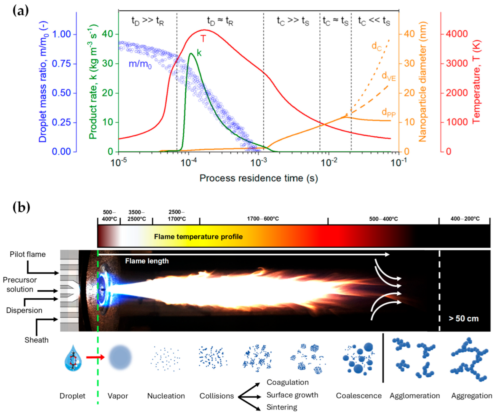
1.2. Process Design
1.3. Recent Advancements in Product/Nanodevice Development
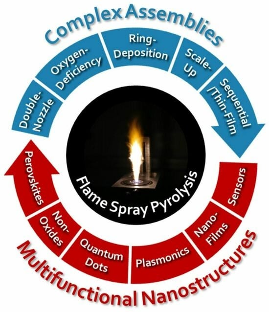
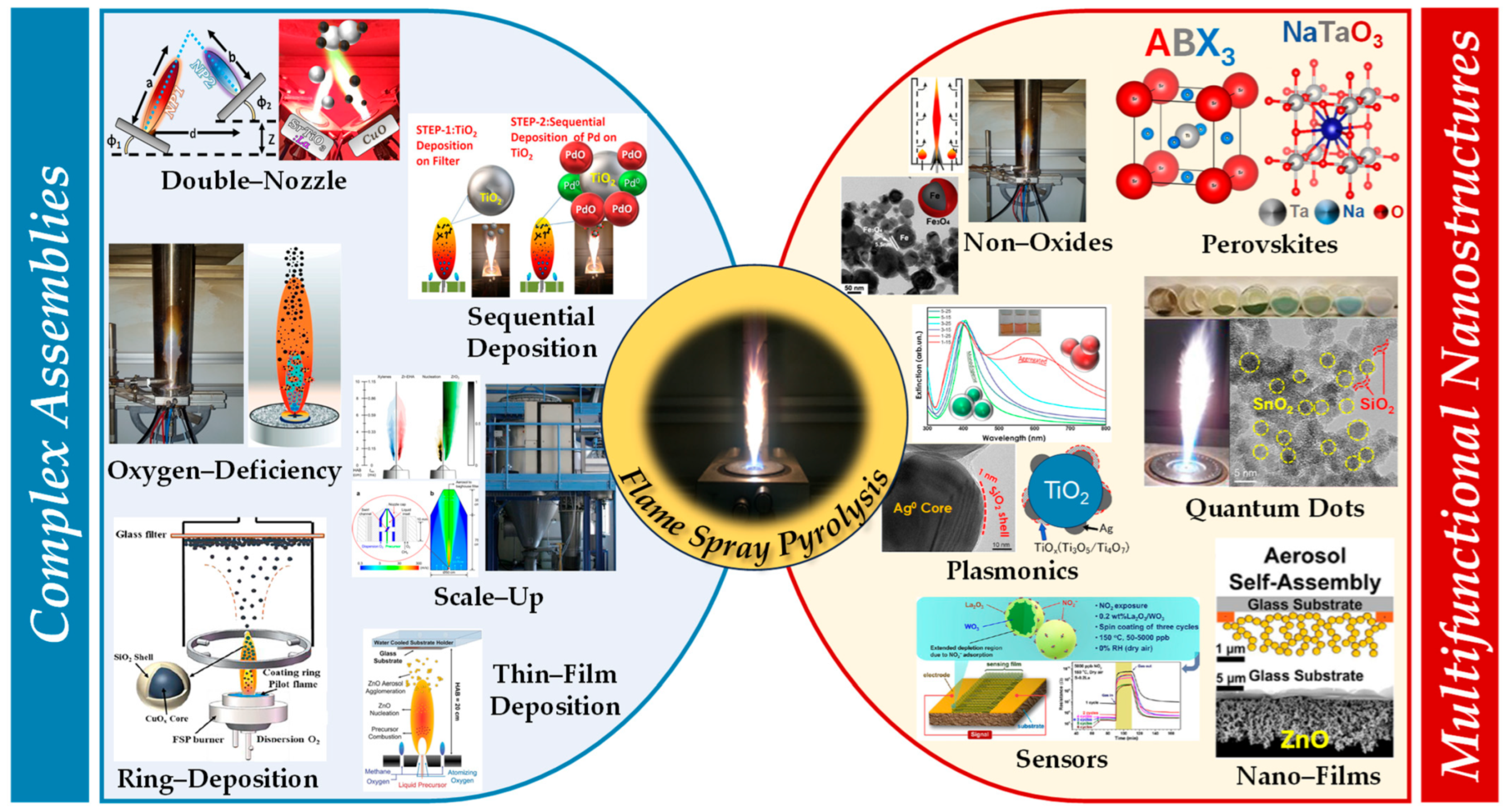
2. Engineering of Complex Nanoassemblies by Flame Spray Pyrolysis
- -
- Oxygen-deficient FSP process,
- -
- Double-nozzle FSP configuration,
- -
- In situ coatings FSP deposition,
- -
- Sequential/nanofilm FSP deposition.
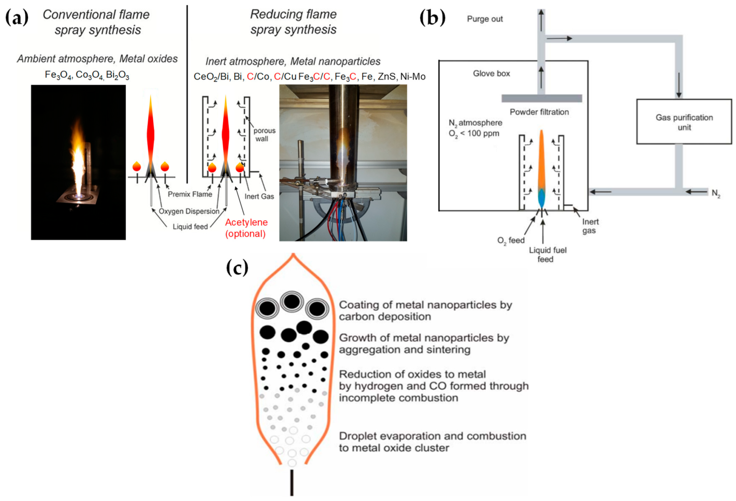
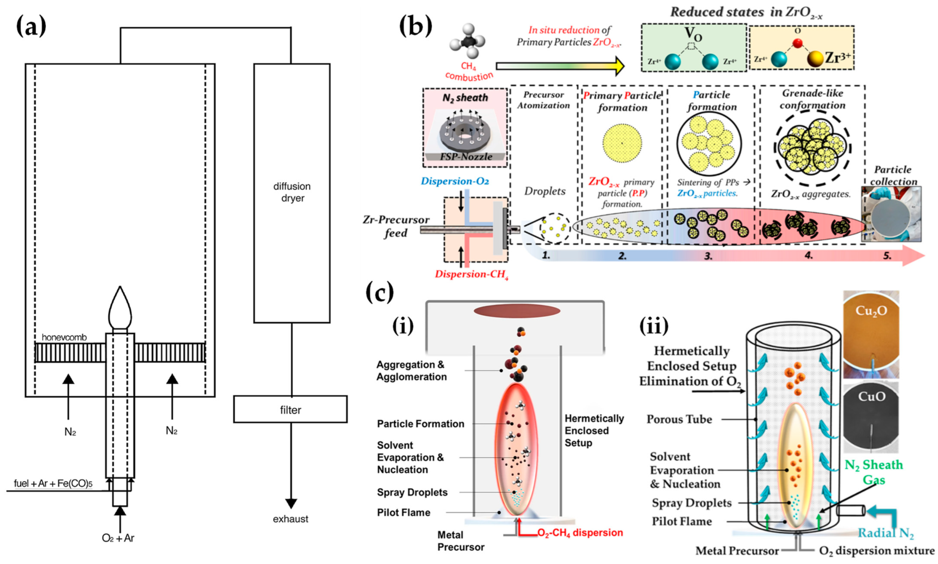
2.1. Oxygen-Deficient FSP Process
- [i]
- O-vacancies generation with no change in the crystal phase: lack of O atoms from the lattice, compared to the formal stoichiometry of the nominal crystal phase, with no modification of the crystal phase.
- [ii]
- Generation or reduced metal atoms with no change in the crystal phase: lack of O atoms from the lattice can stabilize lower-oxidation states of the metal atoms.
- [iii]
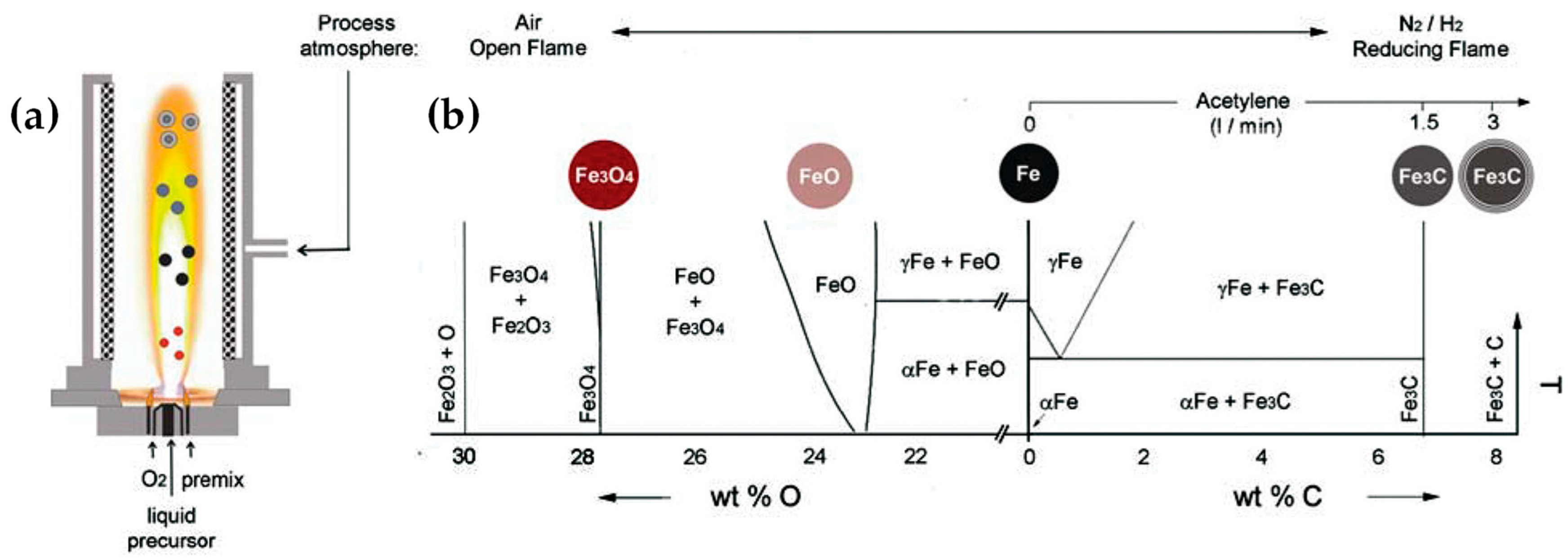
- Stabilization of a reduced crystal phase via lack of O atoms: certain O-deficient metal oxides can stabilize reduced phases. This occurs when a significant fraction part of the metal atoms is reduced. For example, magnetite Fe3O4, which contains one Fe2+ and two Fe3+, can be formed from Fe2O3 (two Fe3+) when 1/3 of the Fe3+-atoms is reduced to Fe2+. Further reduction in all Fe atoms to Fe2+ forms the FeO phase, while further reduction to Fe0-atoms forms the metallic, zero-valent-iron material. Similarly, Cu2O (SnO) is formed when all Cu2+ (Sn4+) atoms in CuO (SnO2) are reduced to the Cu1+ (Sn2+) state.

| Nano- Structure | FSP Configuration | Precursor(s) | Solvent | Molarity (mol L−1) | Precursor Flow (mL min−1) | Pilot Flame O2/CH4 (L min−1) | N2 Flow (L min−1) | Ref. |
|---|---|---|---|---|---|---|---|---|
| C-Co | The flame is encased in a porous tube enabling the addition of inert cooling gases and acetylene. The flame is operated in a glove box in an N2 atmosphere at an O2 < 100 ppm. | Cobalt(II) 2-ethylhexanoate | Tetrahydrofuran | 6 | 2.2/1.2 | 45 | [48,57] | |
| Bi | The spray nozzle was placed in a Glove box fed with N2. A sinter metal tube (inner diameter 25 mm) surrounding the flame allowed for N2 radial flow. | Bismuth(III) 2-ethylhexanoate | Tetrahydrofuran | 6 | 2.2/1.2 | 25 | [46] | |
| CeO2/Bi | Bismuth(III) 2-ethylhexanoate, Cerium(III) octoate | Tetrahydrofuran | 6 | 2.2/1.2 | 45 | [45] | ||
| C-Cu | The flame is encased in a porous tube enabling the addition of inert cooling gases. The flame is operated in a glove box in an N2 atmosphere at an O2 < 100 ppm. | Cu(II)-2-ethylhexanoate | Tetrahydrofuran | 4.5 | 2.2/1.2 | 45 | [47] | |
| Ni-Mo | Ni(II)-ethylhexanoate, Mo(II)-ethylhexanoate | Tetrahydrofuran | 6 | 2.2/1.2 | 45 | [49] | ||
| FexOy | FSP nozzle with an Inconel metal tube (ID = 4 cm, length = 40 cm). Water was fed into this nozzle and dispersed by N2 gas. | Fe(III) nitrate nonahydrate, Fe(II) naphthenate | 2-ethylhexanoic acid/THF/ethanol (2/2/1) | 0.9 | 5 | 2.5/1 | 40 | [51] |
| α-Fe/Fe3O4 | Laminar, inverse diffusion flame stabilized on a burner. | Iron pentacarbonyl | [52] | |||||
| ZrO2–x | A single-nozzle FSP reactor featuring an enclosed flame utilizing a mixture of dispersion gases, O2 and CH4, to establish a reductive reaction environment. | Zirconium(IV) Propoxide | Xylene/acetonitrile (2.2/1.0) | 0.25 | 3 | 4/2 | 15 | [54] |
| C@Cu2O/ CuO/Cu0, Cu2O/CuO | A single-nozzle FSP reactor featuring enclosed flame utilizing a mixture of dispersion gases, O2 and CH4, to establish a reductive reaction environment. A perforated tube permits the introduction of radial N2 gas. | Copper(II) nitrate trihydrate | Acetonitrile/ ethylenglycol (1/1) | 0.25 | 3 | 2/1.2 | 10 | [55,56] |
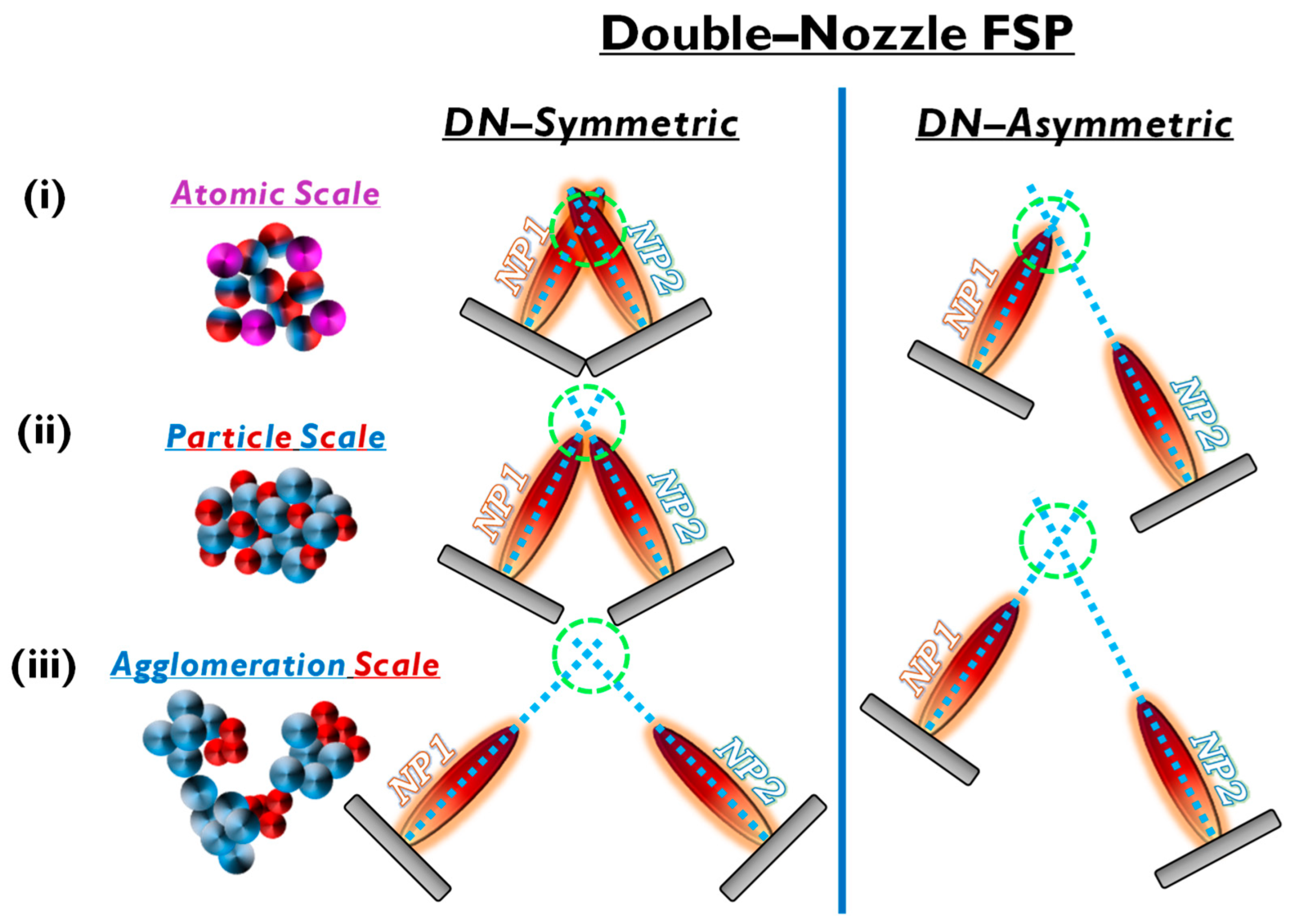
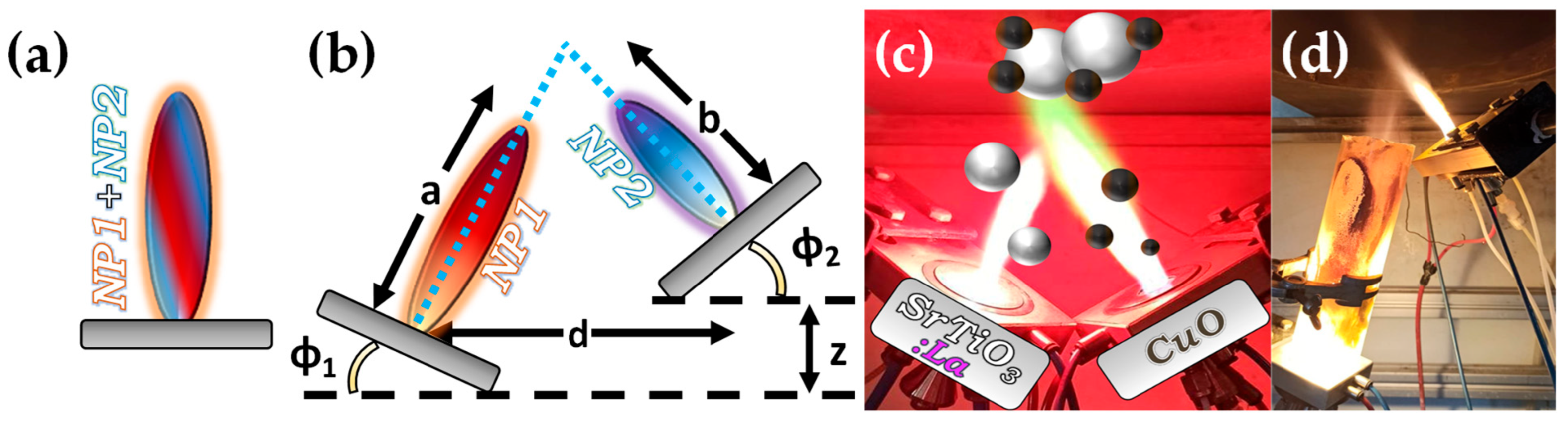
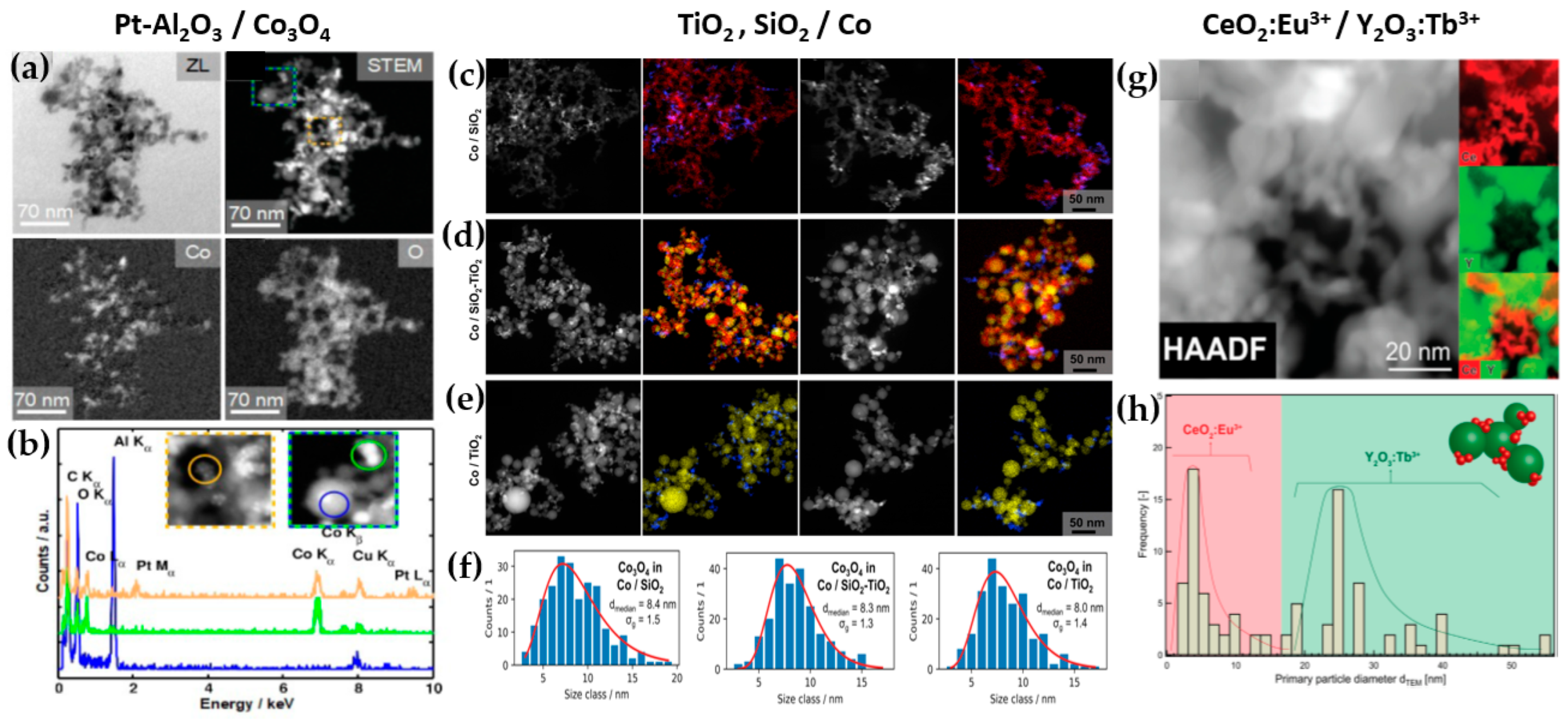
2.2. Double-Nozzle FSP Configuration
| Nanomaterial | Geometric Parameters (cm) | Precursor(s) * | Molarity * (mol L−1) | Precursor * (mL min−1) | Oxygen * (L min−1) | Size (nm) | SSA (m2 g−1) | Ref. |
|---|---|---|---|---|---|---|---|---|
| Symmetric DN–FSP | ||||||||
| Al2O3/Pt/Ba | φ = 30°, d = 3–7 | Al(III) tri-sec-butoxide/ Ba(II) 2-ethylhexanoate, Pt(II) acetylacetonate | 0.5/ 15.4 wt% Ba, <1 wt% Pt | 5/ 3 | 5/ 5 | 10–20 | 120–160 | [59] |
| Al2O3/Co | φ = 20°, d = 11, a = 16 | Al-sec-butoxide/Co naphthenate | 0.5/ 10 wt% Co | 5/ 5 | 5/ 5 | 15–30 | 111–122 | [63] |
| TiO2/Pt0, Pd0, Au0, Ag0 | φ = 30°, d = 11 | Ti(IV) isopropoxide/ Pt(II), Pd(II), Au(III), Ag(I) acetylacetonate | 0.64/ 0–5 wt% | 5/ 3–7 | 5/ 3–7 | 10–20 | 72–200 | [68] |
| TiO2-SiO2/ Co | φ = 20° d = 15, a = 22 | Ti(IV) isopropoxide, TEOS/ Co naphthenate | 0.9/ 9 wt% Co | 5/ 5 | 5/ 5 | 7–16 | 86–284 | [65] |
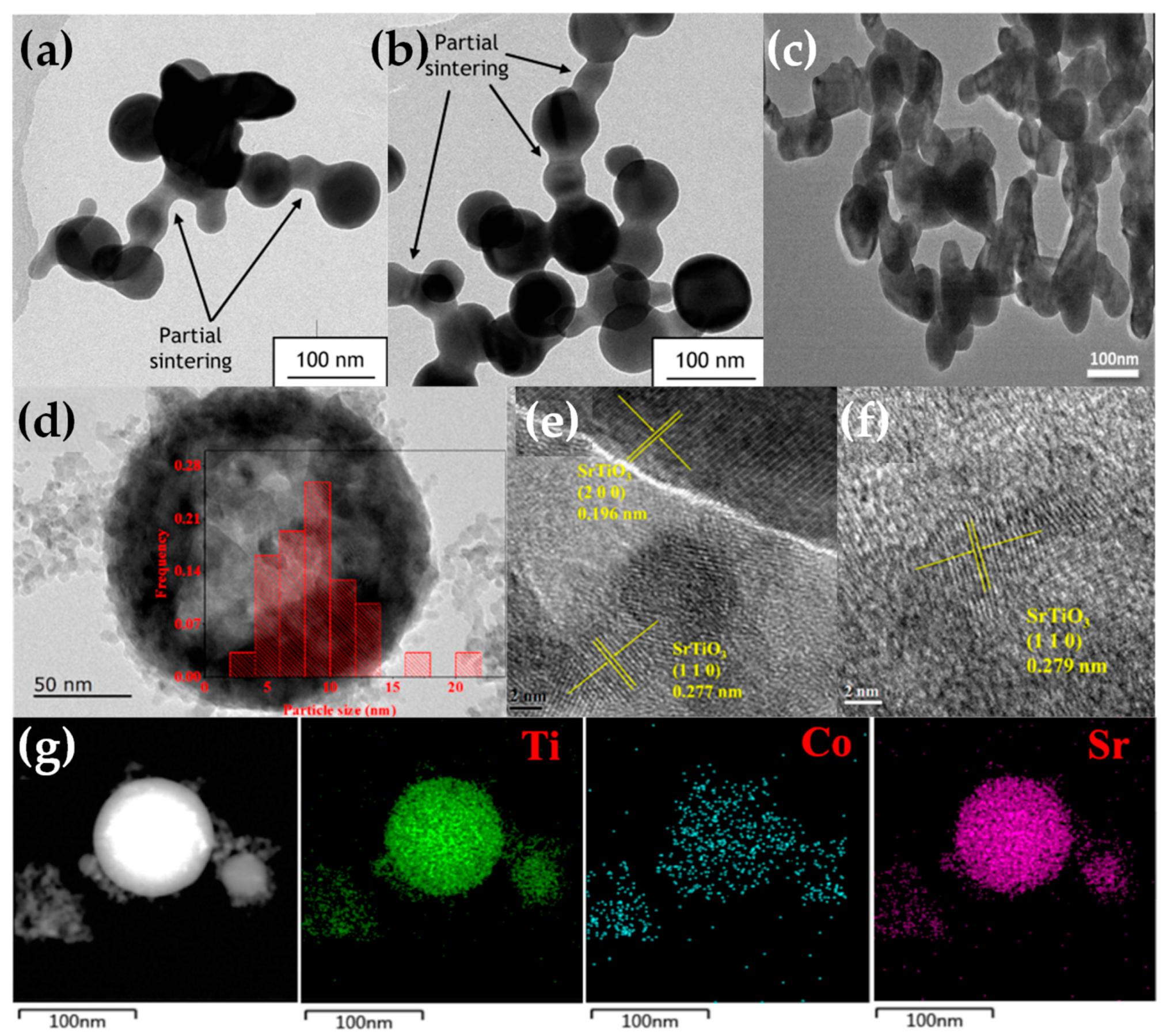
| SrTiO3/CuO | φ = 20°, d = 8, a = 10 | Sr acetate, Ti(VI) isopropoxide/ Cu(II) nitrate trihydrate | 0.4/ 2–0.5 wt% Cu | 5/ 5 | 5/ 5 | 45–55 | 32–57 | [58] |
| ZrO2/CuO | φ = 10° | Zr 2-ethylhexanoate/Cu(II) 2-ethylhexanoate | 0.5/ 11 wt% Cu | 5/ 5 | 5/ 5 | 10–20 | 106–114 | [69] |
| LiMn2O4/AlPO4 | φ = 20°, d = 17 | Li and Mn(III) acetylacetonate/Al-tri-sec-butoxide, triethyl phosphate | –/ 0–5 wt% AlPO4 | 3–7/ 5 | 3–7/ 5 | 7–22 | 64–195 | [70] |
| CeO2:Eu3+/ Y2O3:Tb3+ | φ = 30° | Ce 2-ethylhexanoate/Y nitrate hexahydrate | 0.3/ 0.4 | 3–12/ 3–12 | 3–8/ 3–8 | 5 | 185 | [66] |
| Asymmetric DN–FSP | ||||||||
| SiO2/Ce0.7 Zr0.3O2 | φ1 = 20°, φ2 = 35°, a = 23, b = 5 d = 11, z = 10 | TEOS/Ce 2-ethylhexanoate, Zr(IV) n-propoxide | 0.5/ 0.19 | 3–7/ 5 | 5/ 5 | 18.5–28.5 | 217–363 | [71] |
| NaTaO3/NiO–Pt0 | φ1 = 30°, φ2 = 15°, a = 20, b = 24, d = 11, z = 3 | Na 2-ethylhexanoate, Ta(V) chloride/Ni(II) 2-ethylhexanoate, Pt(II) acetylacetonate | 0.1–0.6/ 0.5 wt% Ni, 0.5 wt% Pt | 3–9/ 5 | 3–9/ 5 | 12–34 | 19–84 | [72] |
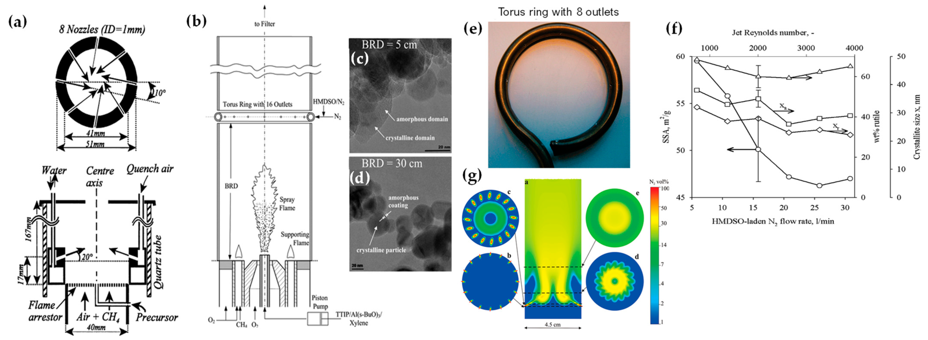
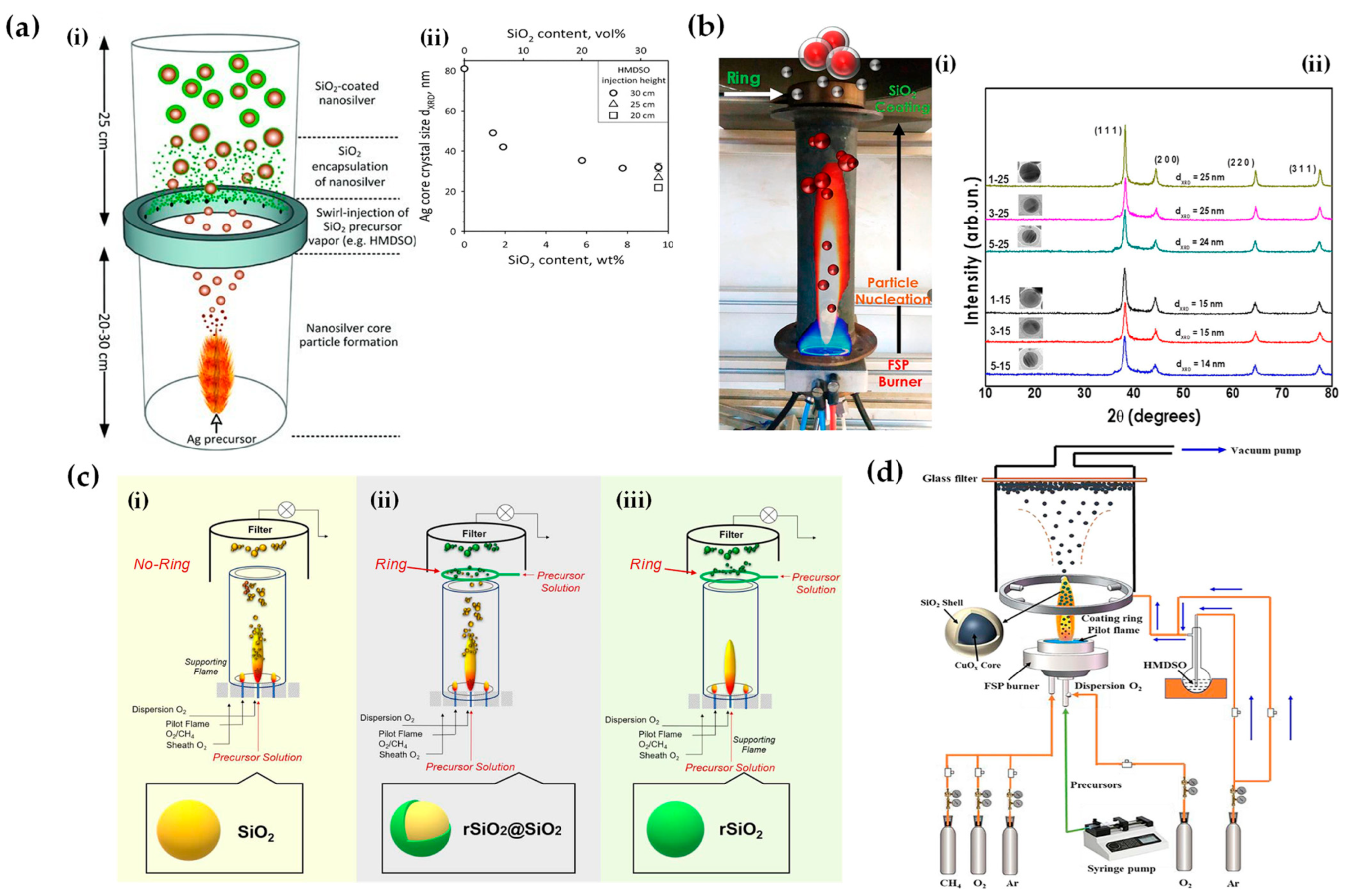
2.3. In Situ Coatings by FSP
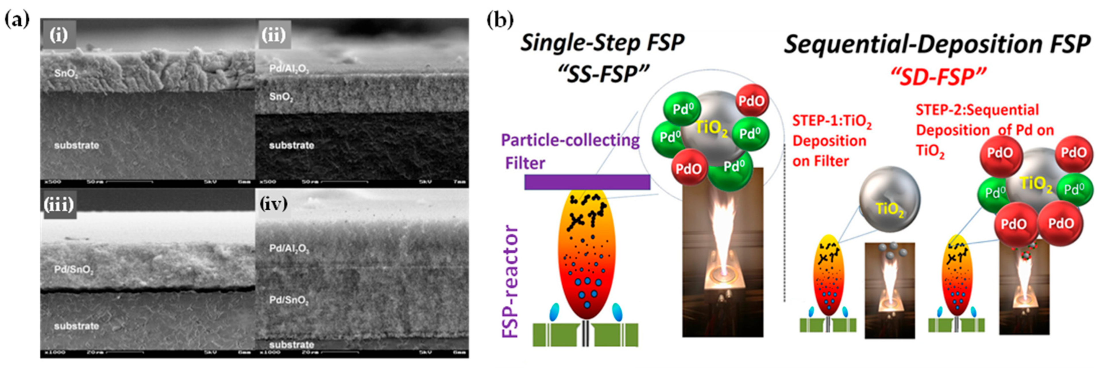
2.4. Sequential FSP Deposition
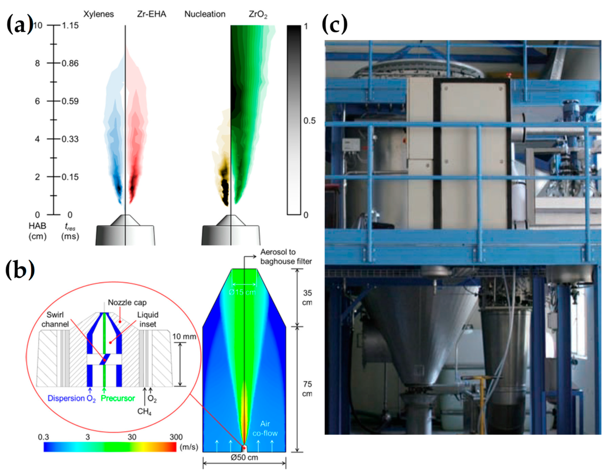
2.5. Scale-Up FSP
| Nanomaterial | Production Rate (kg h−1) | Precursors | Solvents | Molarity (mol L−1) | Precursor (mL min−1) | Oxygen (L min−1) | Size (nm) | SSA (m2 g−1) | Ref. |
|---|---|---|---|---|---|---|---|---|---|
| SiO2 | 1.1 | HMDSO | Ethanol | 4.7 | 33.3 | 50 | 26 | 108 | [115] |
| ZrO2 | 0.6 | Zr n-propoxide | Ethanol | 1 | 81 | 50 | 30 | 33 | [116] |
| ZrO2 | 0.5 | Zr 2-thylhexanoate | Xylene | 1 | 64 | 80 | 25 | 42 | [117] |
| Y2O3/ZrO2 | 0.35 | Zr n-propoxide/Y nitrate hydrate | Ethanol | 0.5 | 81 | 50 | 31 | 32 | [119] |
| FePO4 | 0.27 | Fe nitrate/tributyl phosphate | 2-ethylhexanoic acid | – | 20 | 40 | 129 | 108 | [108] |
| ZnO | 3 | Zinc nitrate hexahydrate | Ethanol, methanol, 1-propanol, 1-octanol | 3.3 | 200 | 120 | 30 | 26.2 | [120] |
| Ca2SiO4 (Belite) | 0.03 | TEOS/calcium propionate | Ethanol, methanol, deionized water | 1.1 | 30 | 30 | 54 | 34 | [121] |

3. Complex Functional FSP Nanostructures and Nanodevices
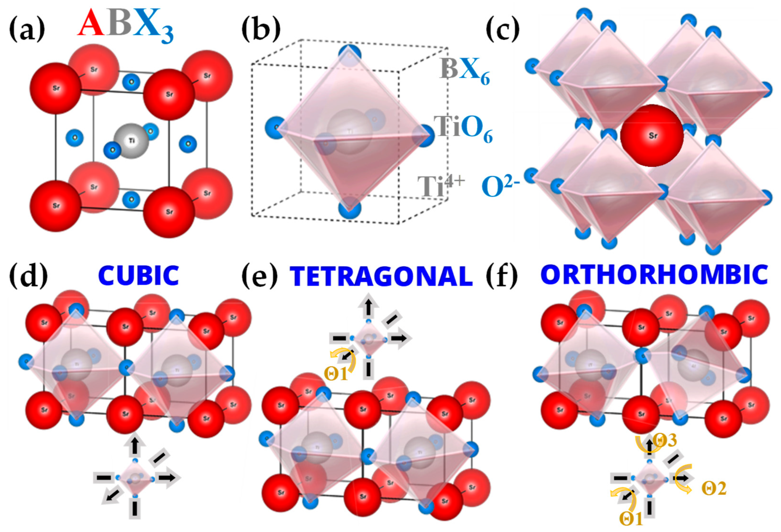
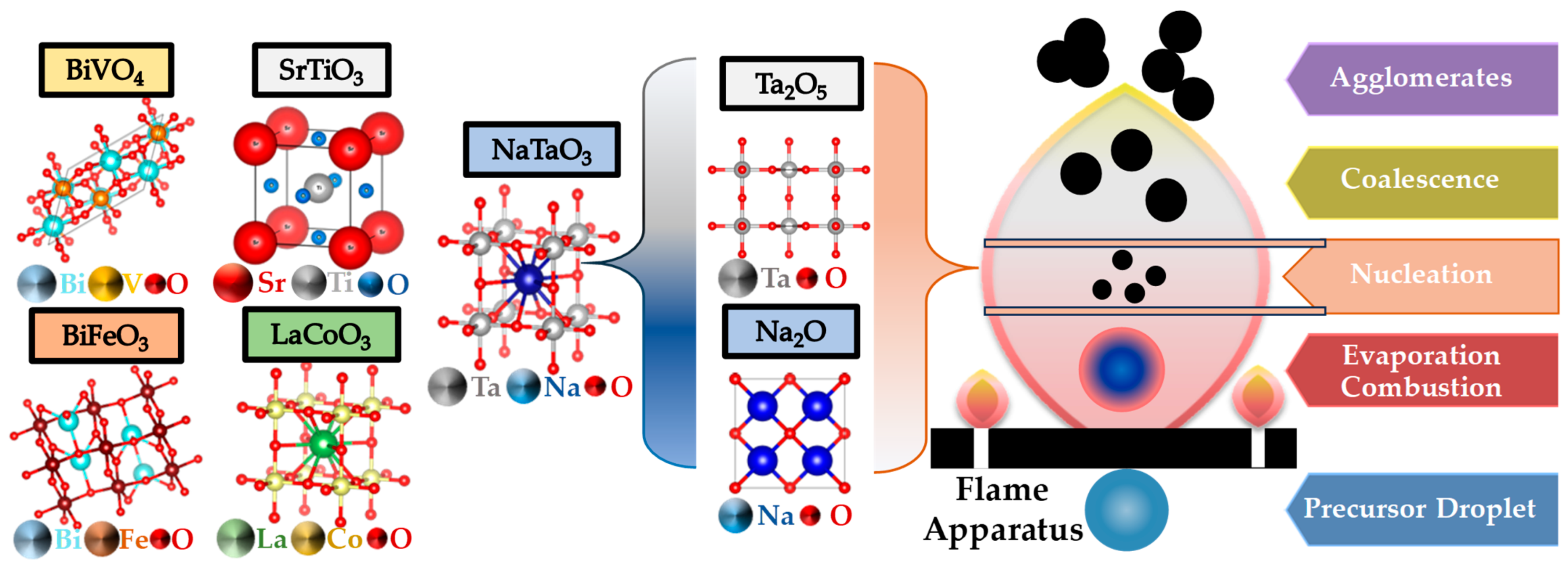
3.1. Engineering of Perovskites by FSP
| Nanomaterial | Precursors | Solvents | Molarity (mol L−1) | Precursor (mL min−1) | Oxygen (L min−1) | Size (nm) | SSA (m2 g−1) | Ref. |
|---|---|---|---|---|---|---|---|---|
| BiVO4 | Bi acetate/V oxytripropoxide | 2-ethylhexanoic acid/xylene | 0.25 (Bi)/ 0.25 (V) | 10 | 5 | 62–71 | 7–12 | [122] |
| W-, Zr-BiVO4 | Bi(III) nitrate pentahydrate/V(V) oxytripropoxide | Ethoxy triglycol, acetic acid (70/30 v/v)/xylene (Total: 50/50 v/v) | 0.5 (Bi)/ 0.5 (V) | 5 | 5 | 15–22 | 38–49 | [123] |
| BiFeO3 | Bi(III) acetate/ Fe(III) acetylacetonate | 2-Ethylhexanoic acid/xylene (50/50 v/v) | 0.1 (Bi)/ 0.1 (Fe) | 3 | 7 | 48–67 | 11–14 | [125] |
| Bi2WO6 | Bi(III) nitrate pentahydrate/ W(VI) ethoxide | Ethanol, acetic acid (70/30 v/v) | – | 5 | 5 | 198 | 3.3 | [126] |
| LaCoO3 | Co(II) nitrate hexahydrate/Fe(III) nitrate nonahydrate | Methanol | 0.3 (La)/ 0.3 (Co) | – | 5 | 10 | – | [127] |
| LaFeO3 | La nitrate hexahydrate/Fe(III) nitrate nonahydrate | Ethanol | – | – | 5 | 10 | – | [128] |
| SrTi1−xBxO3 | Sr acetate/ tetrabutyl titanate | Acetic acid/ethanol (50/50 v/v) | 0.075 (Sr)/ 0.075 (Ti)/ | 3 | 5 | 19–37 | 31–46 | [129,130,131] |
| SrTiO3/CuO | Sr acetate/Ti(VI) iso-propoxide | Acetic acid/xylene (50/50 v/v) | 0.2 (Sr)/ 0.2 (Ti)/ | 5 | 5 | 45–55 | 32–57 | [58] |
| NaTaO3/ NiO–Pt0 | Na 2-ethylhexanoate/ Ta(V) chloride | Ethanol | 0.05–0.3 (Na)/ 0.05–0.3 (Ta) | 3–9 | 3–9 | 12–34 | 19–84 | [72,132] |

3.2. Engineering of Metal Non-Oxides by FSP

| Nano- Structure | FSP Configuration | Precursor(s) | Solvent(s) | Molarity (mol L−1) | Pilot Flame O2/CH4 (L min−1) | Precursor Flow (mL min−1) | Oxygen Flow (L min−1) | Reducing N2 Flow (L min−1) | Size (nm) | SSA (m2 g−1) | Ref. |
|---|---|---|---|---|---|---|---|---|---|---|---|
| Sulfides | |||||||||||
| ZnS:Mn2+ | Glove box with N2 atmosphere, two adsorption columns | Zn 2-ethylhexanoate, Mn naphthenate | Tetrahydrofurane, tetrahydrothiophene | 0.25 [S:Zn = 5:1, Mn:Zn = 1/100 at.%] | 2.2/1.2 | 6 | 5 | O2 < 250 ppm | 23 | 33 | [50] |
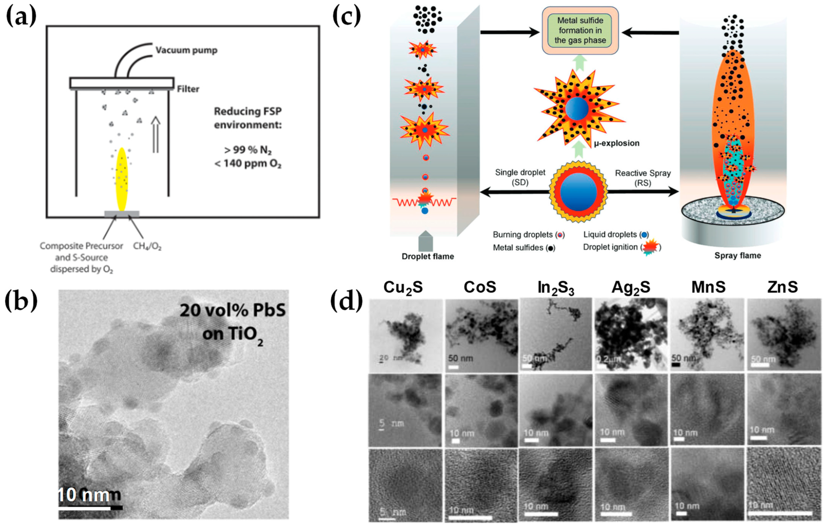
| PbS–TiO2 | Enclosed box under N2 purge | Pb(II) 2-ethylhexanoate, Ti(IV) isopropoxide, thiophene | Ethylhexanoic acid, THF (2:1) | S/Pb = 2.5 | 2.4/1.13 | 5 | 4–4.5 | >99% N2, O2 < 140 ppm | PbS/TiO2 = 2/10 | 75–85 | [142] |
| MnS | Enclosed reactive spray (large tube) reactor, N2 co-flow through porous ring, additional N2 flow via quenching ring | Mn naphthenate | Tetrahydrothiophene | 0.25 [Mn:S = 1:34] | 2.2/1.2 | 3 | 2.46 | 250 | 13.4 | 62 | [143] |
| CoS | Co naphthenate | Tetrahydrothiophene | 0.25 [Co:S = 1:34] | 2.2/1.2 | 3 | 2.46 | 250 | 13.4 | 10 | [143] | |
| Cu2S | Cu naphthenate or Cu 2-ethylhexanoate | Tetrahydrothiophene | 0.25 [Cu:S = 1:20, 1:41] | 2.2/1.2 | 3 | 2.43–5.61 | 250 | 20.5 | 46 | [143] | |
| ZnS | Zn naphthenate | Tetrahydrothiophene | 0.25 [Zn:S = 1:43] | 2.2/1.2 | 3 | 2.36 | 250 | 5.0 | 64 | [143] | |
| Ag2S | Ag 2-ethoxyhexaonate | Tetrahydrothiophene | 0.25 [Ag:S = 1:45] | 2.2/1.2 | 3 | 2.30 | 250 | 11.6 | [143] | ||
| In2S3 | In acetylacetonate | Tetrahydrothiophene | 0.25 [In:S = 1:43] | 2.2/1.2 | 3 | 2.35 | 250 | 11.6 | 103 | [143] | |
| SnS | Sn 2-ethylhexanoate | Tetrahydrothiophene | 0.25 [Sn:S = 1:42] | 2.2/1.2 | 3 | 2.41, 4.83 | 250 | 11.2 | 106 | [143] | |
| Bi2S3 | Bi neodecanoate | Tetrahydrothiophene | 0.25 [Bi:S = 1:35] | 2.2/1.2 | 3 | 2.45 | 250 | 20.2 | 28 | [143] | |
| Carbides | |||||||||||
| Fe3C | Glove box with radial N2 atmosphere, optional acetylene flow | Carbonyl iron Fe +2-ethylhexanoic acid heating at 140 °C for 24 h→Fe(III)-2-ethylhexanoate | Tetrahydrofuran | 0.5 | 2.2/1.2 | 6 | 5 | 25 | 30 | 30.5 | [140] |
| Halides | |||||||||||
| CaF2 | Open-flame FSP reactor, sheath gas O2 (230 L h−1) through a con-centric sinter metal ring | Ca hydroxide, hexafluorobenzene | 2-ethylhexanoic acid, xylene | 2.4/1.13 | 5 | 5 | – | 14 | 139 | [144] | |
| SrF2 | Sr acetate, hexafluorobenzene | 2-ethylhexanoic acid, xylene | 2.4/1.13 | 5 | 5 | – | 17 | 84 | [144] | ||
| BaF2 | Ba acetate, hexafluorobenzene | 2-ethylhexanoic acid, xylene | 2.4/1.13 | 5 | 5 | – | 34 | 36 | [144] | ||
| Ho–BaF2 | Ba acetate, ho oxide, hexafluorobenzene | 2-ethylhexanoic acid, xylene | 2.4/1.13 | 5 | 5 | – | 26 | 48 | [144] | ||
| NaCl | Sodium hydrogencarbonate, chlorobenzene | 2-ethylhexanoic acid, xylene | 2.4/1.13 | 5 | 5 | – | 92 | 30 | [144] | ||
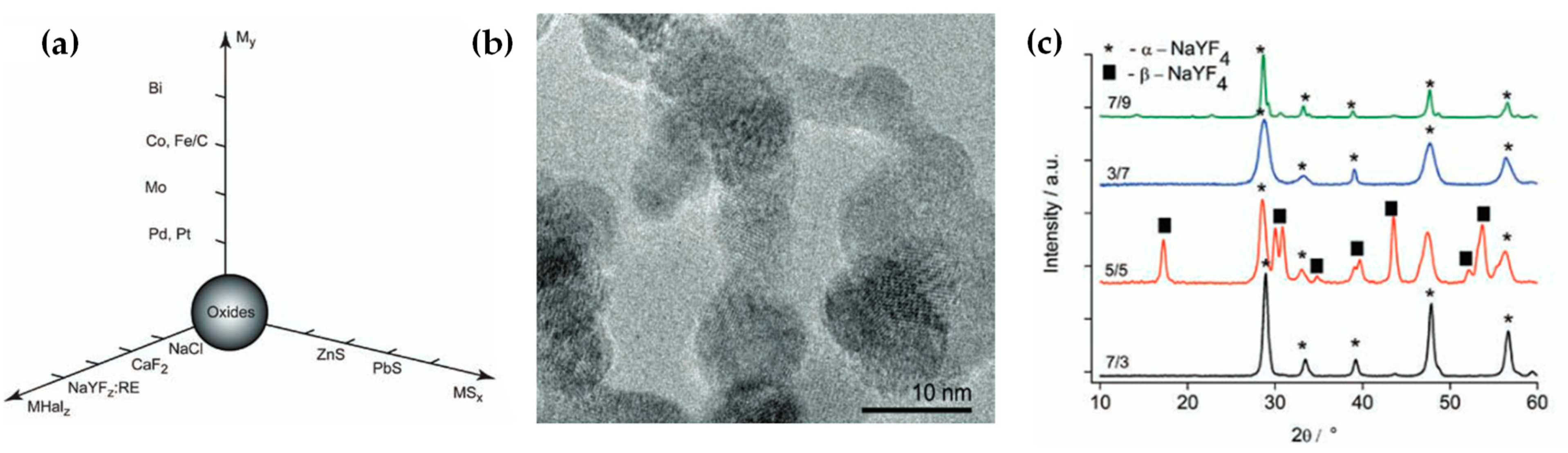
| NaYF4:Yb (Tm, Er) | Glove box with N2 gas flow | Tm acetate, Y acetate, Yb acetate, Er acetate, sodium bicarbonate | 2-ethylhexanoic acid, xylene | 3, 5, 7, 9 | 7, 5, 3 | O2 < 100 ppm | 20–40 | 29.5–31 | [145] | ||
| Phosphates | |||||||||||
| VOPO4 | The solution was stirred at 60 °C and aged for 1 day | Ammonium vanadate, ammonium dihydrogen phosphate, sucrose | Deionized water, dimethyl-formamide | 0.1 | 3/1 | 5 | 5 | – | 21.7–26.3 | [146] | |
| FePO4 | Open-flame FSP reactor | Fe(III)-acetylacetonate, tri-butylphosphate | Xylene | 0.2 | 2.4/1.13 | 3–7 | 3–8 | – | 30.5, 10.7 | 68.6, 194.7 | [147] |
| FePO4 | Open-flame FSP reactor | Fe(III) nitrate nonahydrate | Denaturized absolute ethanol, tributyl phosphate, 2-ethylhexanoic acid | 0.2 | 2.5/1.25 or 2/3–9 | 2–6 | 6 | – | 10–20 | 104 | [148] |
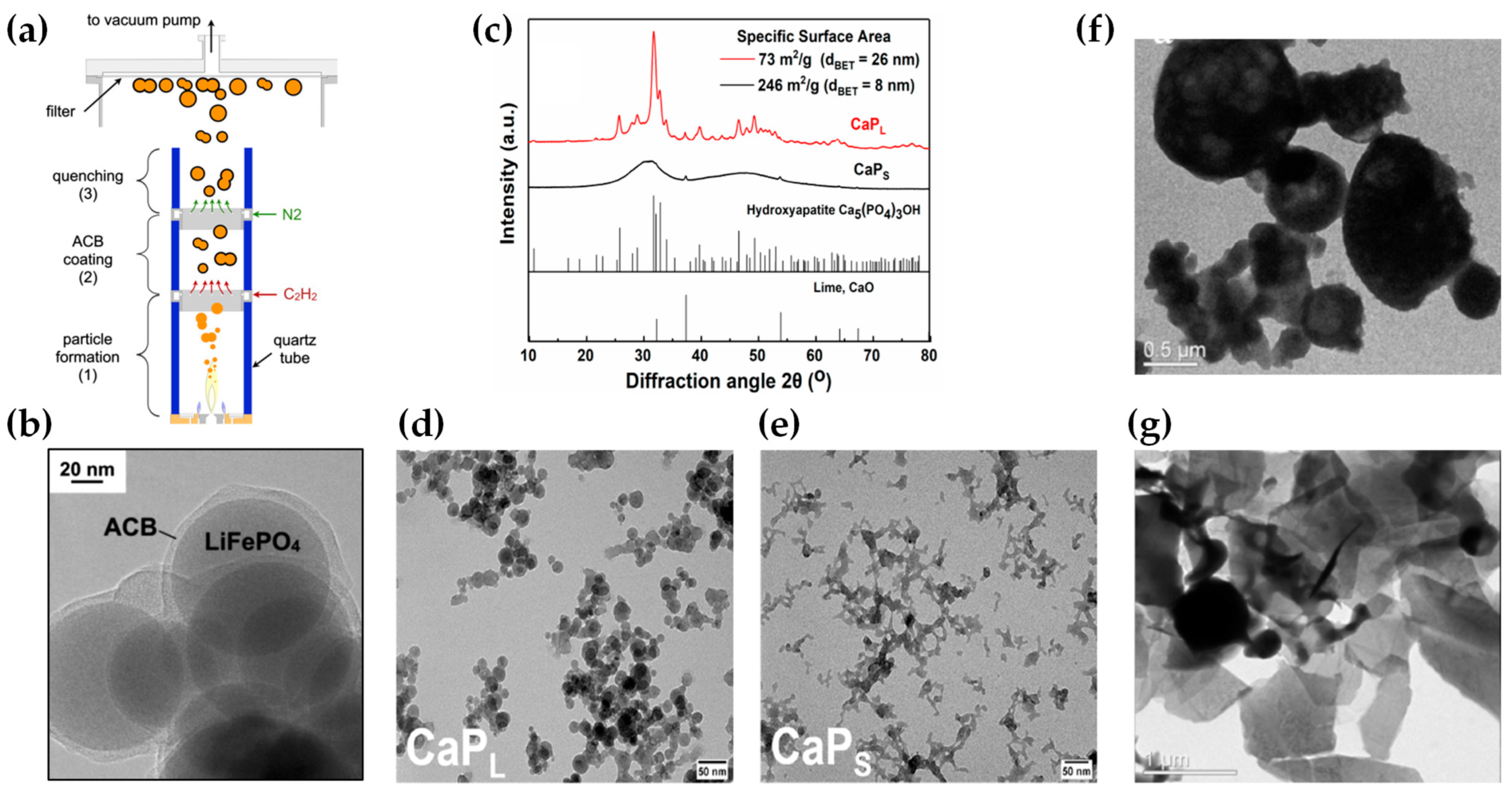
| Carbon-coated LiFePO4 | Enclosed FSP with quartz tubes, C2H2 and N2 gas flows, sheath O2/N2 mixture (19 L min−1) | Li-acetylacetonate, Fe(III) acetylacetonate, tributyl phosphate | 2-ethylhexanoic acid, toluene, diethylene glycol monobutyl ether, ethanol | 0.24 [Li:Fe:P = 1:1:1] | 2.5/1.25 | 3 | 3 | 20 L min−1 N2, 1 L min−1 C2H2 | 58 | 30 | [149] |
| LiTi2(PO4)3 | Open-flame FSP reactor | Li t-butoxide, Al tri-sec-butoxide, Ti isopropoxide, trimethyl phosphate | 2-methoxyethanol | 2.8 | 5/5.2 | 12.5 | 20 | – | < 50 | [150] | |
| LiGe2(PO4)3 | Open-flame FSP reactor | Li t-butoxide, Al tri-sec-butoxide, Ge ethoxide, trimethyl phosphate | 2-methoxyethanol | 3.2 | 5/5.2 | 12.5 | 20 | – | < 50 | [150] | |
| Biphasic Ca3(PO4)2 | Ultrasonic droplet generator, quartz reactor | Ca Nitrate Tetrahydrate, Diammonium hydrogen phosphate | Ethyl alcohol, distilled water (0.6:0.4) | 0.4 | C3H8 + O2 (5 L min−1) | 5 | 40 | – | 32–38 | [151] | |
| CaP | Open-flame FSP reactor | Ca acetate hydrate, tributyl phosphate | Propionic acid | 0.4 | 2/2 | 2.4 | 9 | – | 23 | 40–50 | [152] |
| CaP:Eu (5 at%) | Open-flame FSP reactor | Ca acetate hydrate, Eu nitrate hexahydrate, tributyl phosphate | 2-ethylhexanoic acid, propionic acid | 0.2, 0.1 | 3.2/1.5 | 8, 3 | 3, 8 | – | 26, 8 | 73, 246 | [153] |
| Carbonates | |||||||||||
| CaCO3 | Open-flame FSP reactor | Ca 2-ethylhexanoate | 2-ethylhexanoic acid, xylene | 0.4 | 3–7 | 3–7 | – | 20–50 | 31.1–102.6 | [154] | |
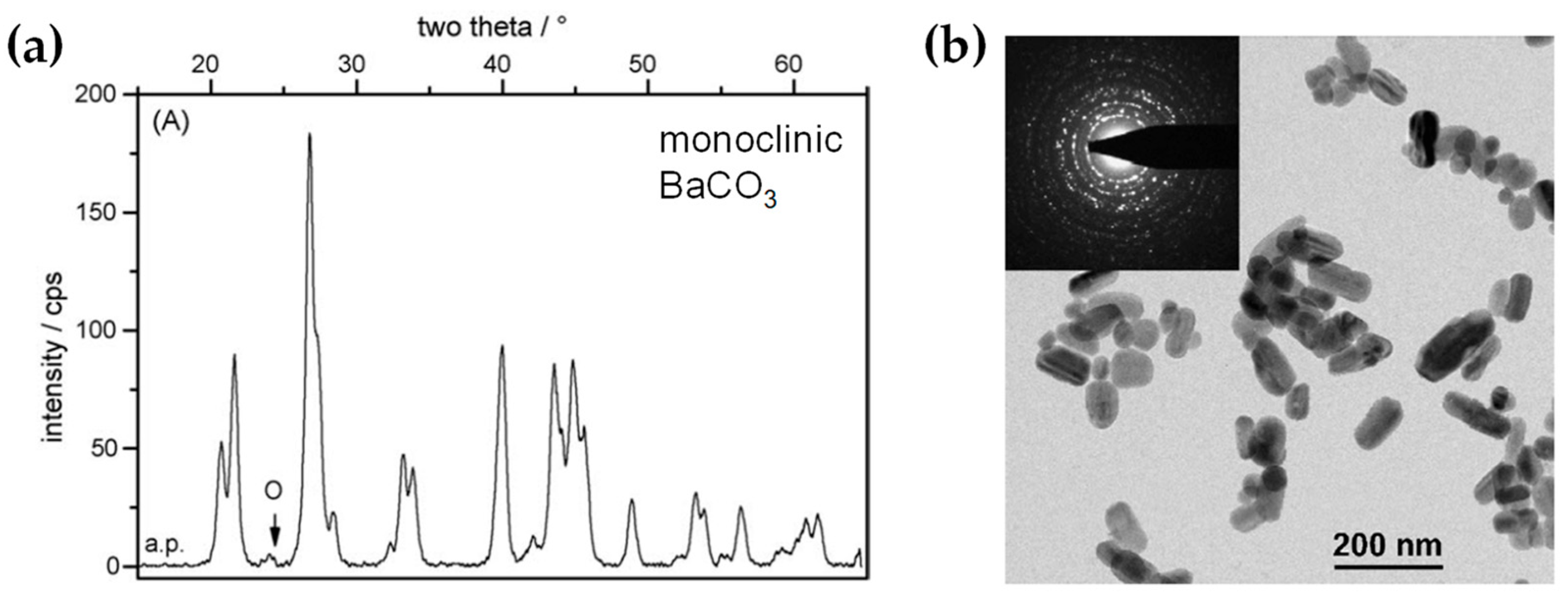
| BaCO3 | Open-flame FSP reactor | Ba(II) 2-ethylhexanoate | Ethanol | 0.2 | 5 | 5 | – | 50–100 | 20.5 | [155] | |
| Pure metals | |||||||||||
| Bi | Glove box with radial N2 flow, two adsorption columns | Bi(III) 2-ethylhexanoate | Tetrahydrofuran | 2.2/1.2 | 2–6 | 2.5–5 | 25 (O2 < 100 ppm) | 51–127 | [46] | ||
| C/Cu | Glove box with N2 flow | Cu(II)-2- ethylhexanoate | Tetrahydrofuran | 2.2/1.2 | 4.5 | 5 | N2: 1–4 m3/h (O2 < 10 ppm) | 10–20 | 67 | [47] | |
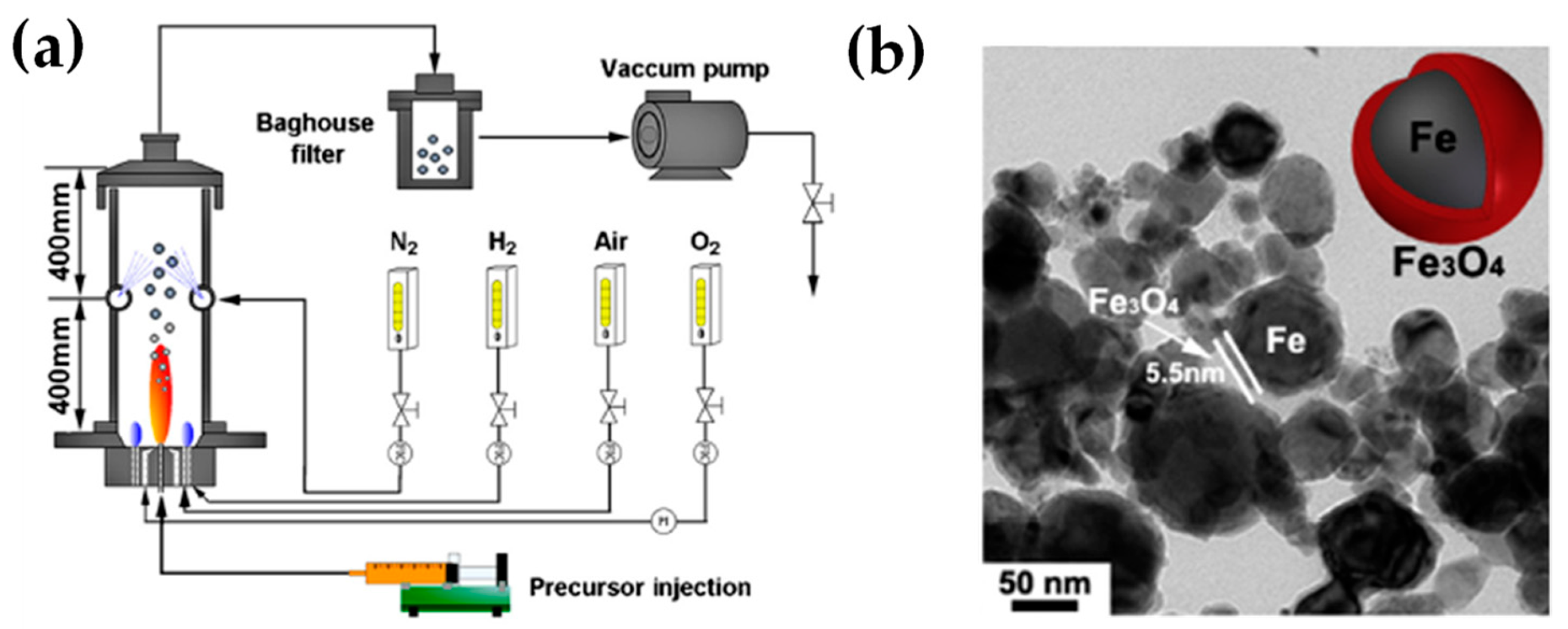
| Fe with Fe3O4 shell | Glove box with N2 flow, supported inverse H2/air diffusion flame | Ferrocene | Xylene, tetrahydrofuran | 0.2–0.8 | 4 | 2.5 | N2: 1.5 m3/h (H2: 0.76 m3/h, air: 0.8 m3/h) | 30–80 | [156] | ||
| Co | Glove box with radial N2 or CO2 flow, two adsorption columns | Co 2-ethylhexanoate | Tetrahydrofuran | 2.2/1.2 | 4.5–6 | 5 | N2 or CO2: 25 (O2 < 100 ppm) | 30 | [57] | ||
3.3. Engineering of Metallic Nanoparticles by FSP
3.4. Engineering of Quantum Dots by FSP
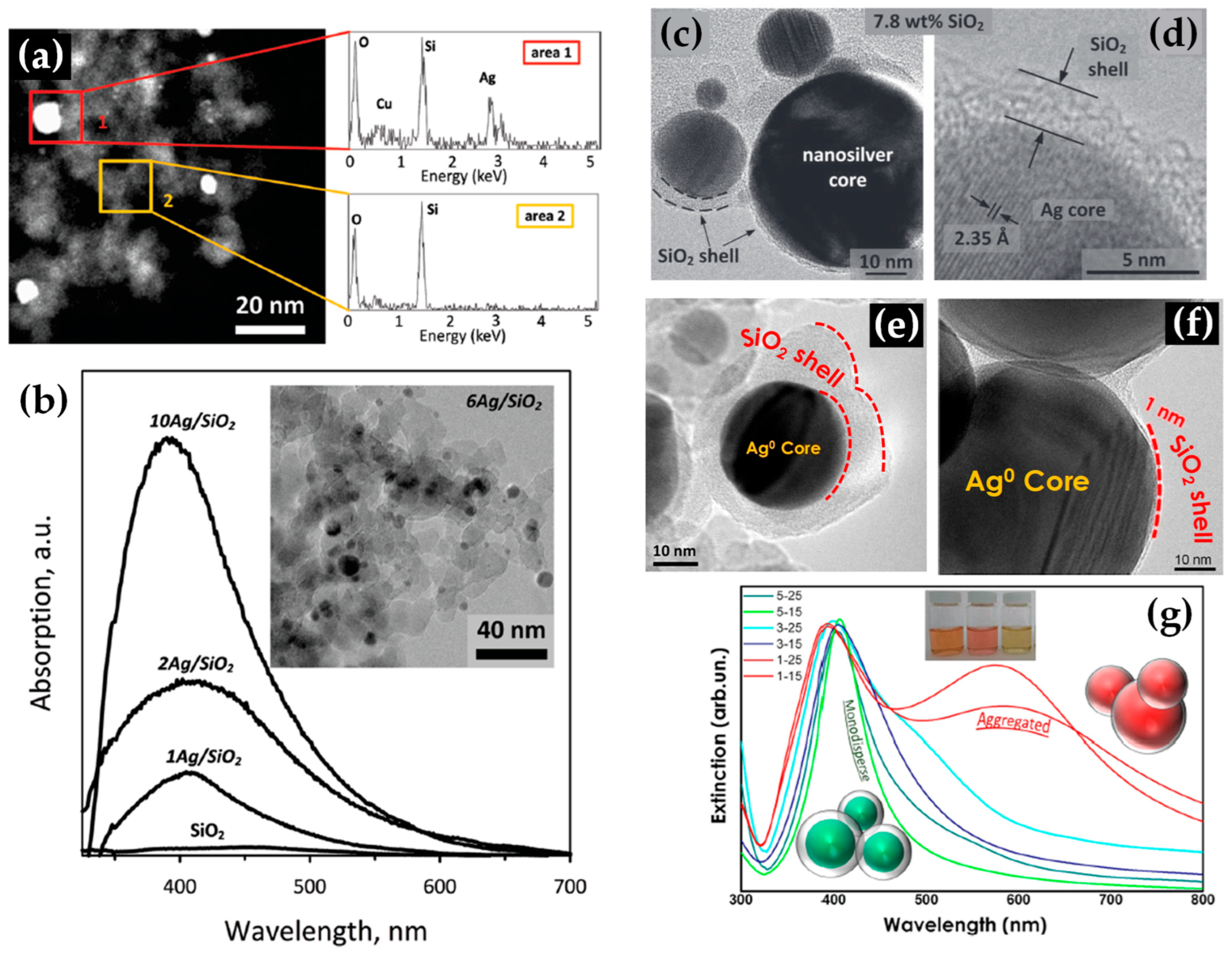
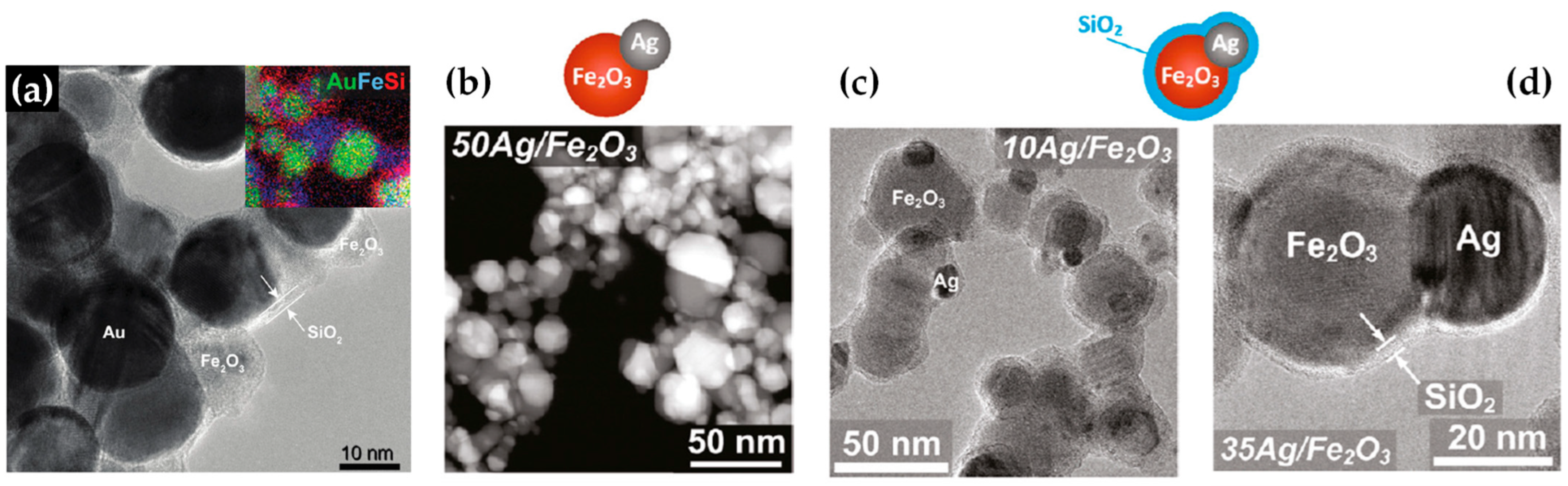
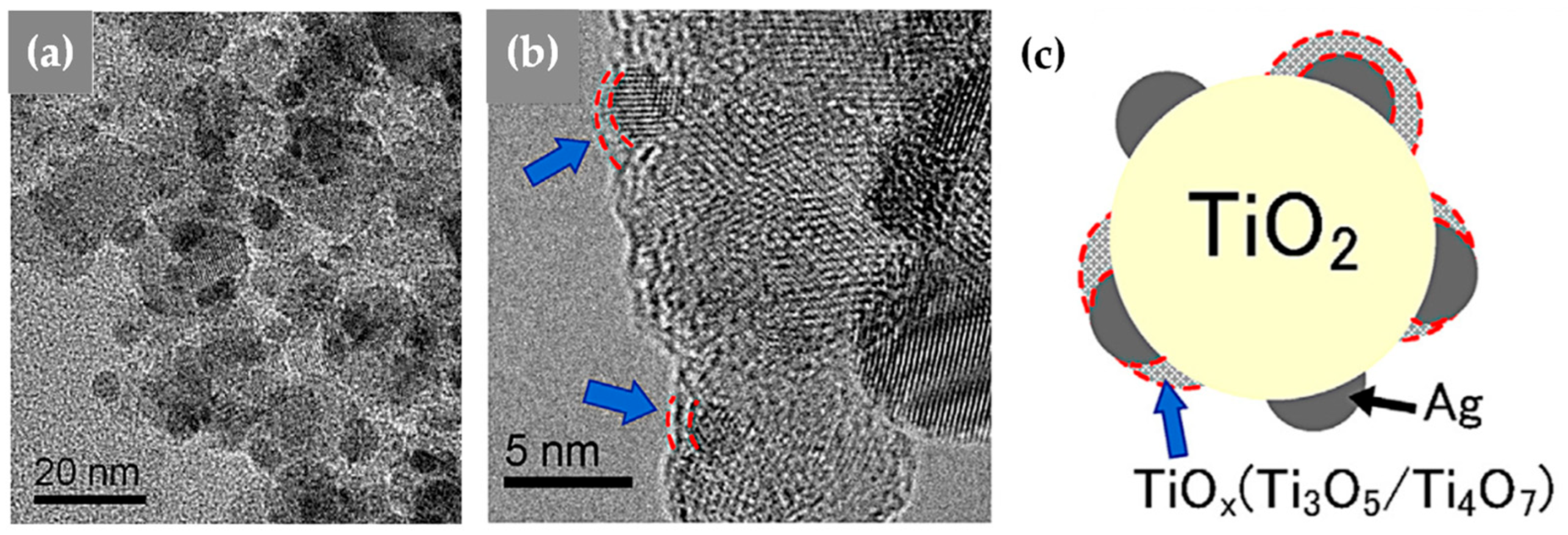
3.5. Engineering of Nanoplasmonics by FSP
| Nano- Structure | FSP Configuration | Precursor(s) | Solvent(s) | Molarity (mol L−1) | Pilot Flame O2/CH4 (L min−1) | Precursor Flow (mL min−1) | Oxygen Flow (L min−1) | Sheath Oxygen (L min−1) | Size (nm) | Ref. |
|---|---|---|---|---|---|---|---|---|---|---|
| Ag/SiO2 | Open-flame FSP reactor, mixed precursors | (a): [Ag nitrate, HMDSO], (b): [Ag acetate, HMDSO], (c): [Ag nitrate, HMDSO] | (a): [Ethanol, diethylene glycolmonobutyl ether], (b): [2-ethylhexanoic acid, toluene], (c): [2-propanol, tetraethyl orthosilicate] | 0.5 | 150 | [202] | ||||
| Core-shell Ag/SiO2 | Enclosed by 2 quartzes tubes of 40 cm + ring deposition with N2 flow (0.8 and 10–30 L min−1) | Ag-acetate, HMDSO | Acetonitrile, 2-ethylhexanoic acid | 3.2/1.5 | 5 | 5 | 40 | Ag: 10–30, SiO2: 3–6 | [79] | |
| Core-shell Ag/SiO2 | Enclosed by quartz tube of 22 cm + ring deposition with N2 flow (0.3–3 and 10–15 L min−1) | Ag-acetate, HMDSO | Acetonitrile, 2-ethylhexanoic acid | 0.3–0.5 SiO2: 8–27 wt% | 5/2.5 | 5–7 | 5 | 5–20 | Ag: 15–25, SiO2: 1–5 | [80] |
| Au/TiO2 | Open-flame FSP reactor, mixed precursors | Ti(IV)-isopropoxide, dimethyl-Au(III) acetylacetonate | Xylene, pyridine (8/2) | 3.1 | 6 | Au: 1–2, TiO2: 9–10 | [209] | |||
| [monometallic Au]–TiO2, Fe2O3/Fe3O4, SiO2 [bimetallic Au/Ag]–TiO2, Fe2O3/Fe3O4, SiO2, Al2O3 | Open-flame FSP reactor, mixed precursors | Dimethyl-Au-(III)-acetylacetonate, silver- (I)-benzoate, Ti(IV)-isopropoxide, Fe(II) naphthenate, tetraethyl ortho-silicate | Xylene, pyridine | 3.5 | 3 | 3 | Au: 1–6, Au/Ag: 1–10, 25–40 | [206] | ||
| Ag/Au–SiO2 | v FSP reactor, mixed precursors | Ag acetate, Au acetate, HMDSO | Acetonitrile, 2-ethylhexanoic acid | 0.15 | 5 | 5 | 4–14 | [210] | ||
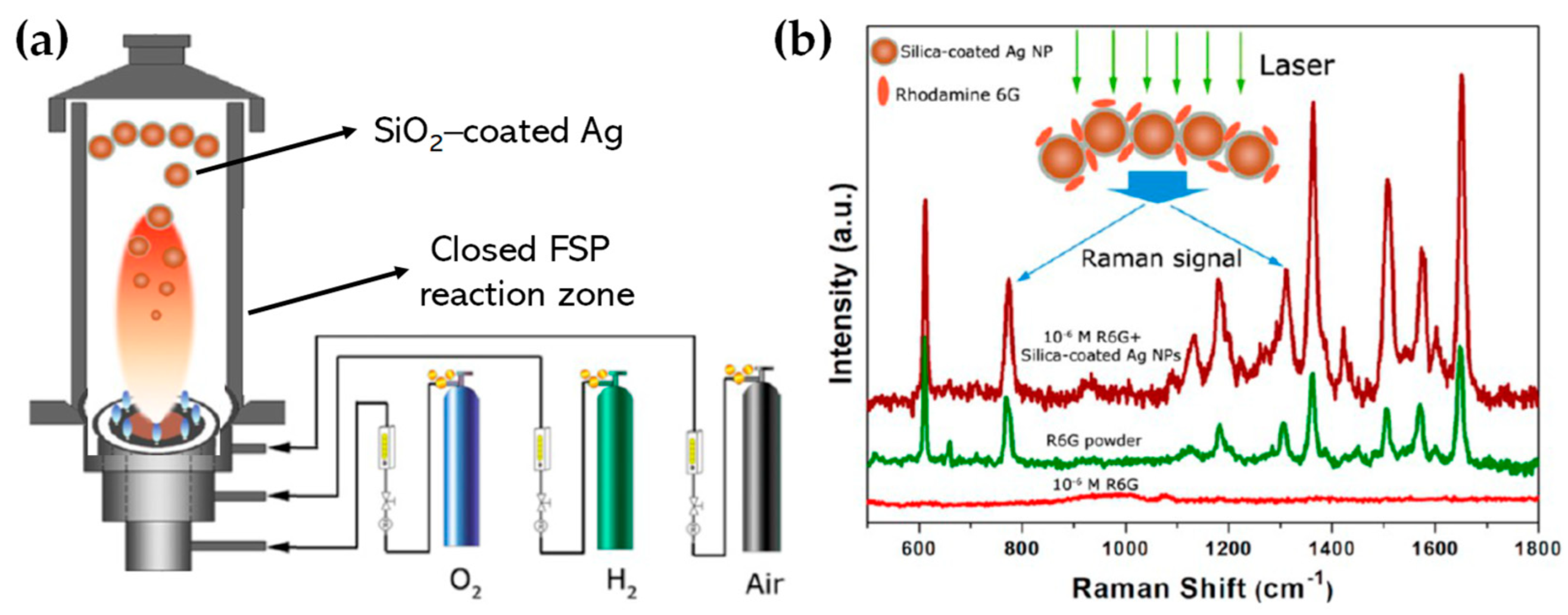
| Ag/SiO2 | Closed FSP reaction zone with a H2/air diffusion flame | Ag nitrate, tetraethyl orthosilicate | Ethanol | 3 | 5 | H2/air: 2/25 L min−1 | 30, SiO2: 1–4 | [211] | ||
| TiO2– Ag/TiOx | Open-flame FSP reactor, mixed precursors | Ag acetate, Ti(IV)-isopropoxide | Acetonitrile, 2-ethylhexanoic acid | 0.16 | 3.2/1.5 | 3, 8 | 5 | 20 | 20, Ag: 3–5 | [212] |
| SiO2-coated Ag/Fe2O3 | Enclosed by 30 cm quartz tube + ring deposition with N2 flow (15 L min−1) + 25 cm quartz tube | Ag acetate, Fe(III) acetylace- tonate, HMDSO | Acetonitrile, 2-ethylhexanoic acid | Fe2O3: 0.5, Ag: 0–50 wt% SiO2: 23 wt% | 3.2/1.5 | 5 | 5 | 40 | Fe2O3: 15, Ag: 10–20, SiO2: 1–2 | [204] |
| SiO2-coated Au/Fe2O3 | Enclosed by 30 cm quartz tube + ring deposition with N2 flow (16 L min−1) + 25 cm quartz tube | Au(III) acetate, Fe(III) acetylace- tonate, HMDSO | Acetonitrile, 2-ethylhexanoic acid | Au: 0.25, Fe2O3: 30 at%, SiO2: 0–13 wt% | 3.2/1.5 | 5 | 5 | 40 | Fe2O3: 50–100, Au: 30, SiO2: 2.6 | [203] |
| Ag/Ca3(PO4)2 | Open-flame FSP reactor, mixed precursors | Ag acetate, Ca hydroxide, tributyl phosphate | 2-ethylhexanoic acid, toluene | 0.75 Ca/P: 1.5 Ag: 0–10 wt% | 5 | 5 | 5 | 4 | Ca3(PO4)2: 20–50, Ag: 1–2 | [213] |
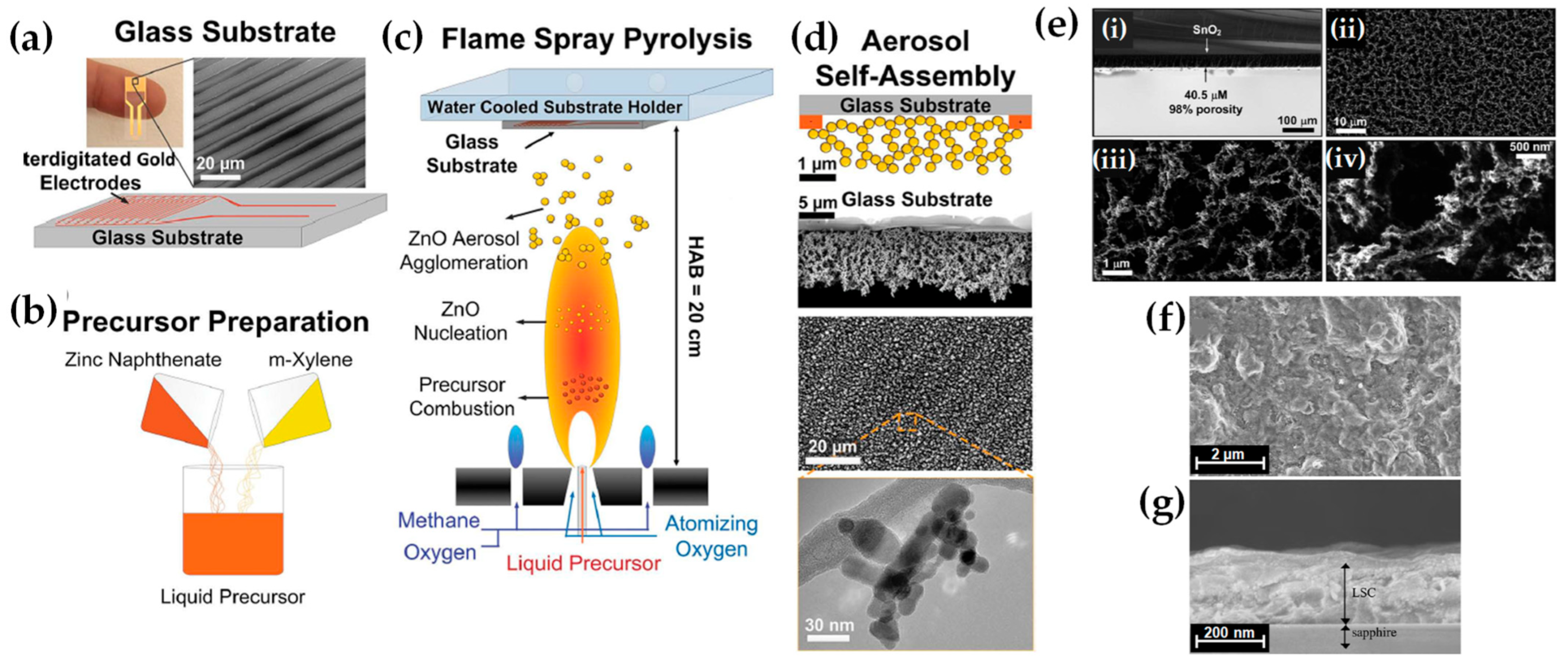
3.6. Nanofilm Engineering by FSP
| Nano-Film | FSP Thin Film Configuration | Precursor(s) | Solvent(s) | Molarity (mol L−1) | Pilot Flame O2/CH4 (L min−1) | Precursor Flow (mL min−1) | Oxygen Flow (L min−1) | Remarks | Size (nm) | Ref. |
|---|---|---|---|---|---|---|---|---|---|---|
| Pt/SnO2 | The open flame FSP reactor was used to directly deposit pa- rticles onto a sensor (alumina) substrate. | Sn(II) 2-ethylhexanoic acid, Pt acetylacetonate | Toluene | 0.5 | 3.2/1.5 | 5 | 5 | Sensor response = 8 for 50 ppm CO at 350 °C | 10 | [92] |
| ZnO, TiO2 | ZnO/TiO2 films are deposited on amorphous silica substrates of 10 mm × 10 mm. | Zn acetate dissolved in deionized water./ Precipitation of hydrous Ti oxide by add- ing ammonia to TiOCl2 solution. The preci- pitate is filtered, washed, mixed with trie-thanolamine, heated at 200 °C for 2 h, and then diluted with deionized water. | 35 g L−1/ 50 g L−1 | C2H2:O2 = (1:1) | 16,000 | Remazol brilliant blue dye is degraded by ZnO and TiO2. Reactivity: ZnO (90% after 60 min) > TiO2. | 100–500 | [96] | ||
| La0.6Sr0.4 CoO3−δ (LSC) | The LSC thin films have been flame spray deposited on sapphire substrates and ceria-gadolinia oxide pellets. | La nitrate, Sr chloride, Co nitrate | N,N-dimethylformamide | 0.006 | 7/2 | 0.5 | 20 | Area-specific resistance (ASR) of 0.96 Ω cm2 at 600 °C. ASR degraded 3.9% in 5 days at 550 °C in the air. | 38 | [223] |
| SnO2, TiO2 | Particles deposited by orthogonal FSP aerosol impingement on a 20 cm temperature-controlled substrate (alumina) holder. | Sn(II)-ethylhexanoate or Ti(VI) isopropoxide | Xylene | 0.1–0.5 | 3.2/1.5 | 5 | 5 | Introduces a theoretical framework for calculating FSP deposition rates based on the thermal gradient (ΔT) between aerosol and substrate interfaces. | SnO2: 10, TiO2: <50 | [98] |
| Ag/PMMA-coated glass substrates | FSP deposition of Ag particles which are sub sequently embedded by spin-coating to form polymer nanocomposite films. | Ag acetate | 2-ethylhexanoic acid and acetonitrile (1:1) | 0.4 | 3.2/1.5 | 3 | 6 | Scalable manufacturing of <1 μm polymeric nanocomposite films with high conductivity (5 × 10⁴ S cm−1), even under repeated bending. | <100 | [224] |
| ZnO ultraporous networks | FSP deposition of ZnO nanoparticle films onto glass substrates with Au interdigitated electrodes. | Zn naphthenate | Xylene | 0.3 | 2/1.2 | 5 | 7 | Photodetector performance achieved the highest reported photo-to-dark-current ratio (3.4 × 10⁵) at very low light intensity (0.1 mW cm−2). | 19 | [93] |
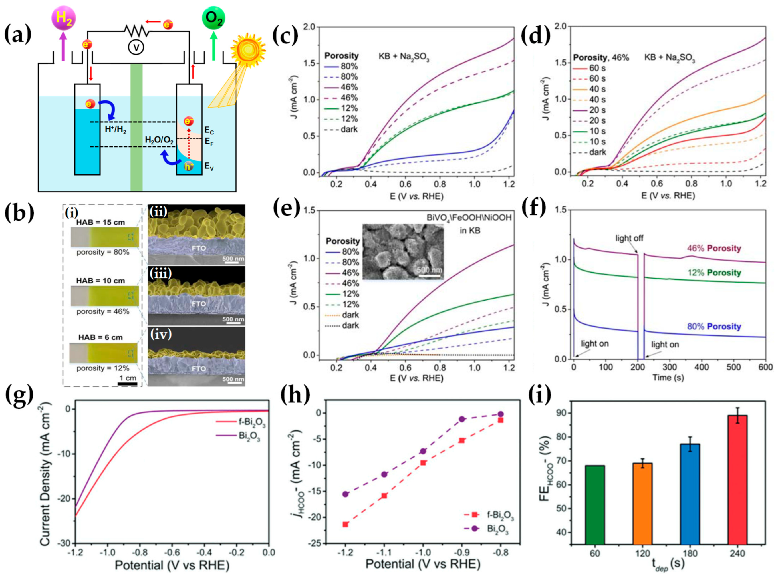
| BiVO4 photoanodes | FSP and thermophoretic deposition of the nanoparticle aerosols directly on FTO glass substrates. | Bi(III) 2-ethylhe- xanoate, vanadyl naphthenate | 2-ethylhexanoic acid and toluene (1:1) | 0.1 | 2/1.8 | 5 | 5 | BiVO4 photoanodes with 46% film porosity and 400 nm thickness, yielding significant photocurrent densities for sulfite (1.5 mA cm−2) and water (1.0 mA cm−2) oxidation. | <400 | [225,226,227] |
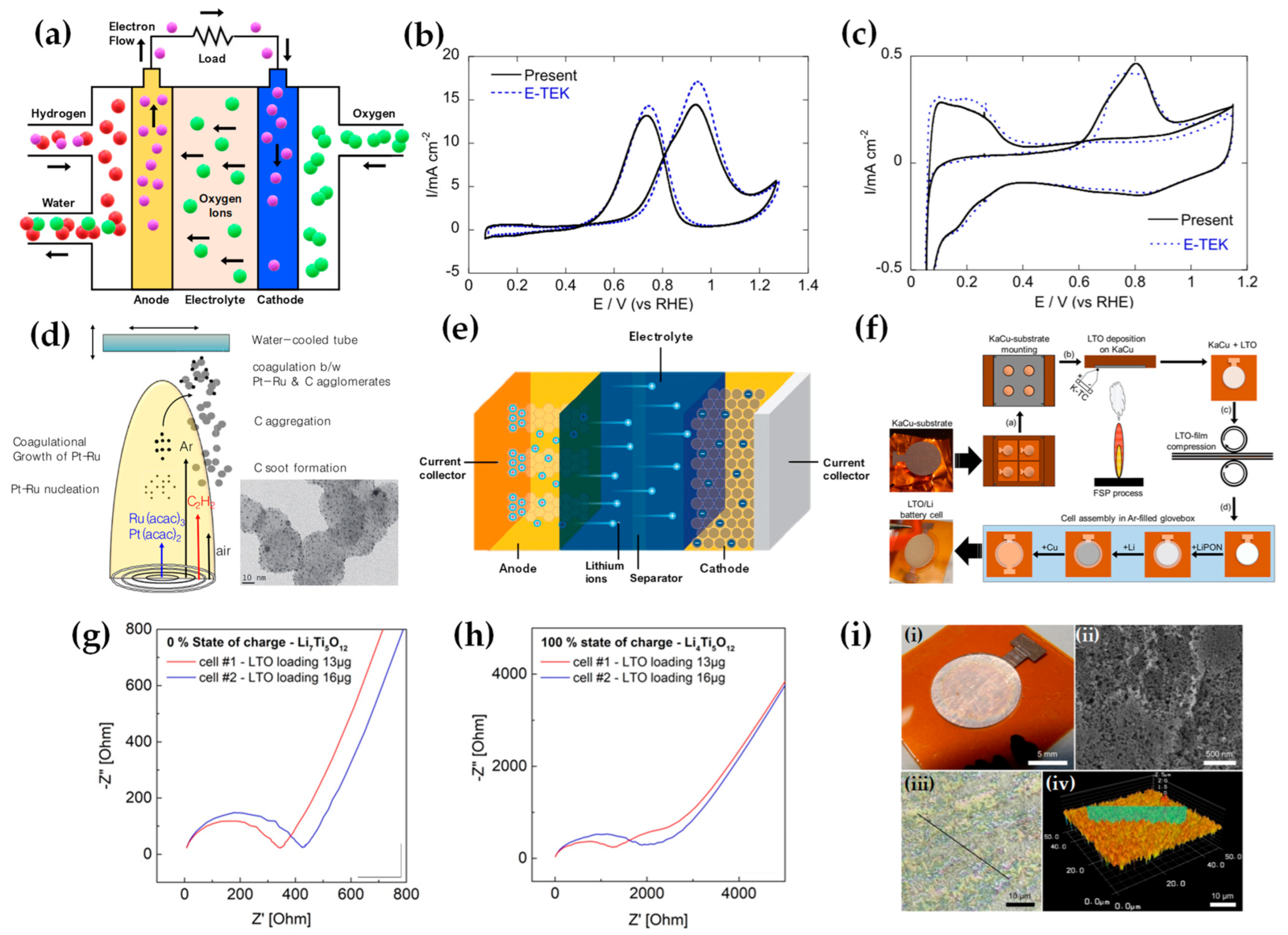
| Pt-Ru | Flame aerosol synthesis of Pt-Ru deposited dire-ctly as a thin layer on the gas diffusion layer. | Ru(III) acetylacetonate, Pt(II) acetylacetonate | Isooctane and tetrahydrofuran (4:1) | 0.5 | 2.2 | Pt-Ru anode electrodes for the direct methanol fuel cell (DMFC). Flame-catalyst surpasses 10%Pt–Ru/C E-TEK commercially with 60% higher activity at 0.4 V for methanol oxidation at 90 °C. | 10.3 | [228] | ||
| Core-shell Ag-SiO2 | FSP and thermophoretic deposition of plasmonic Ag-SiO2 on temperature-controlled cover glasses. | Silver acetate (reflex at 110 °C for 1.5 h), tetraethyl orthosilicate | 2-ethylhexanoic acid and acetonitrile | 3.2/1.5 | 5 | 5 | FSP fabrication of SERS sensing substrates. Excellent performance for detecting pesticide residue in orange juices. | 12 | [229] | |
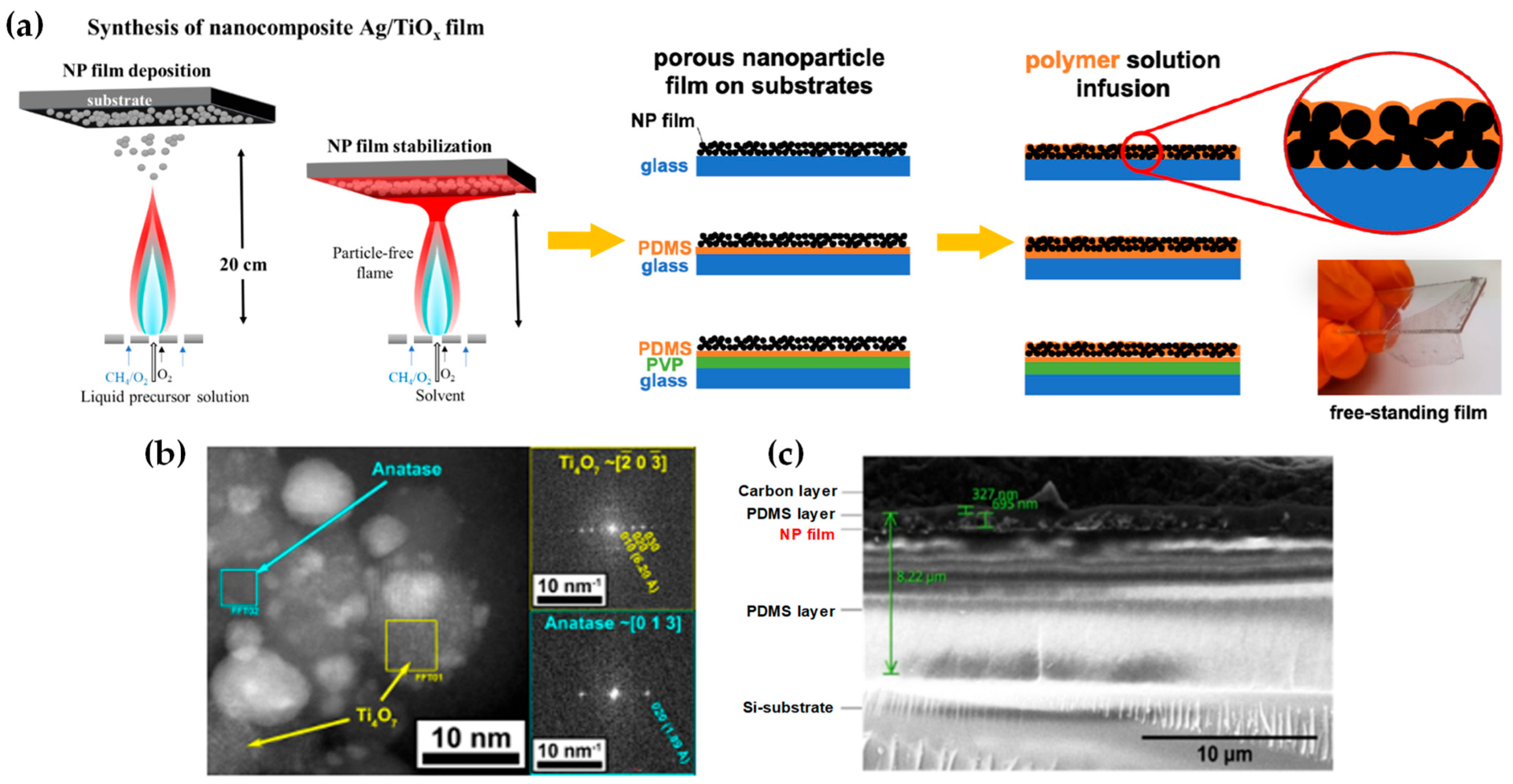
| Ag/TiOx–polymer | Ag/TiOx was FSP and thermophoretically deposited on Si substrates or PDMS polymer layers and mechanically stabilized with ethanol spray annealing. | Silver acetate, Ti(VI) isopropoxide | 2-ethylhexanoic acid and acetonitrile (1:1) | 0.16 | 8 | 5 | The optimized polymer nanocomposite films effectively eradicate biofilms upon short, on-demand visible light exposure of 15–90 min with no cytotoxic effects on mammalian cells. | 190–600 | [230] | |

3.7. FSP Nanostructures for Sensing Applications
| Nano- Device | FSP Setup, Sensor Fabrication | Precursor(s) | Solvent(s) | Molarity (mol L−1) | Precursor Flow (mL min−1) | Oxygen Flow (L min−1) | Sensing Performances | Size (nm) | Ref. | ||
|---|---|---|---|---|---|---|---|---|---|---|---|
| Gas, VOC | Conc. (ppm)/temp. | Response | |||||||||
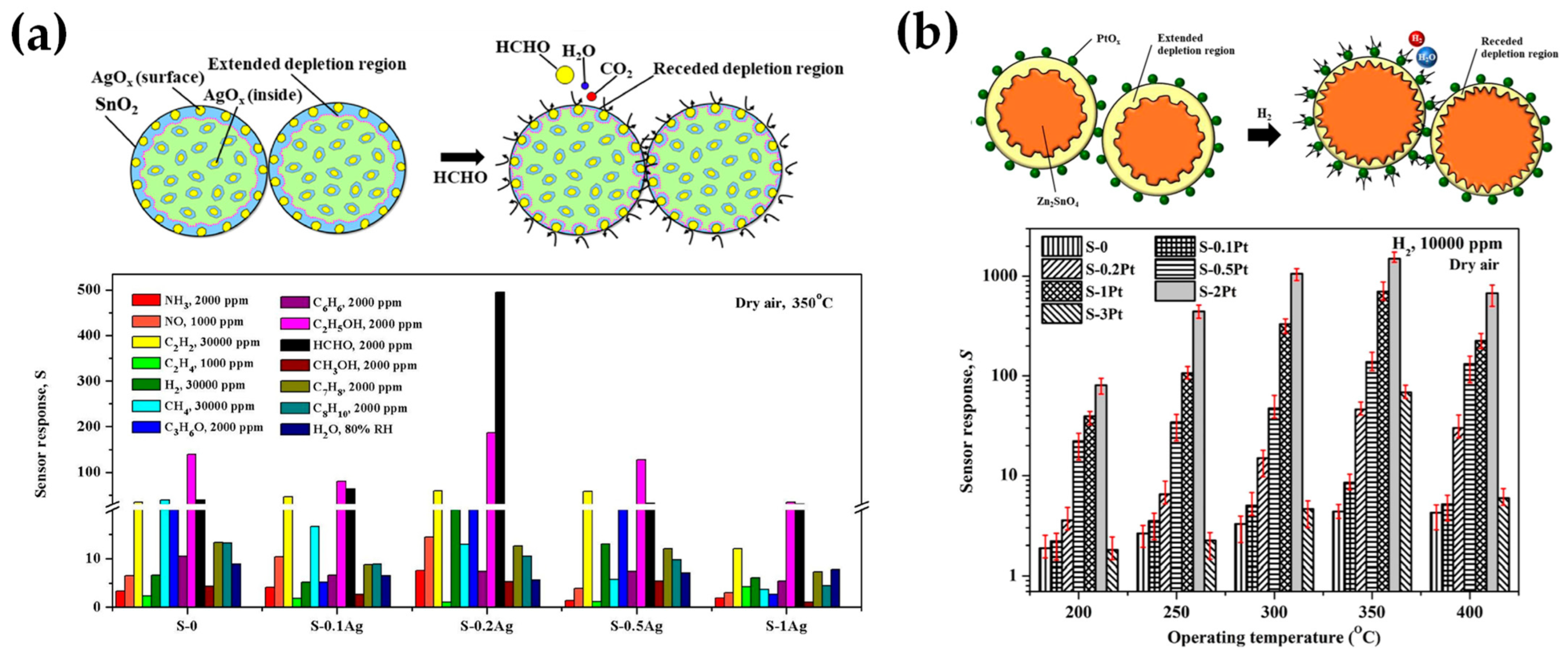
| AgOx–doped SnO2 | c FSP reactor, spin coating | Sn(II) 2-ethylhexa-noate, silver nitrate | Xylene, acetonitrile | 0.5 | 5 | 5 | HCHO | 100, 200, 2000/350 °C | 67,107,495 | AgOx: <3, SnO2: 5–20 | [236] |
| PtOx–Zn2SnO4 | Open flame FSP reactor, powder pasting, spin coating | Zn(II) acetylacetonate, Sn(II)2-ethylhexanoate/Pt(II) acetylacetonate | Methanol/xylene | 0.5 | 5 | H2 | 150, 1000, 10,000/350 °C | 30.1, 216.4, 1500.4 | PtOx: 1–3, Zn2SnO4: 30–40 | [237] | |
| Er-doped SnO2 | Open flame FSP reactor, powder pasting, spin coating | Sn(II) 2-ethylhexa-noate, Er(III) acetylacetonate hydrate | Ethanol | 0.5 | C2H4O | 30, 10, 5, 1, 0.05/350 °C | 347, 95, 46, 7.6, 1.3 | 5–20 | [239] | ||
| LaCo1–xFexO3 | Enclosed-flame FSP reactor (pilot flame = CH4: 1.25, O2: 3.2, Ar: 5.0 L min−1), powder pasting, spin coating | La nitrate, Co nitrate, Fe nitrate | Methanol | 0.3 | 5 | NH3 | 20–70/475 °C | Sensitivity: 87.22 mV/decade | 10 | [127] | |
| Nb-doped SnO2 | Open flame FSP reactor, powder pasting, spin coating | Sn(II) 2-ethylhexa-noate, Nb(V) ethoxide | Absolute ethanol | 0.5 | 5 | 5 | C2H2 | 1000/350 °C | 776 | 5–15 | [238] |
| Graphene/Rh–doped SnO2 | Open flame FSP reactor, electrolytic exfoliation, powder pasting, spin coating | Rh(III) acetylacetonate, Sn(II) 2-ethylhexanoate | Xylene | H2S | 10/350 °C | 439 | 5–20 | [240] | |||
| Ga2O3/Nb | Open flame FSP reactor with chamber, post-annealing | Potassium acetylacetonate, gallium nitrate in dichloromethane/Nb(V) 2-ethylhexanoate | Toluene | 0.2 | 3 | 1.5 | C3H6O, H2, CH4 | 20/470 °C, 20/500 °C, 10,000/500 °C | 9.8, 2.5, 4 | <3 | [241] |
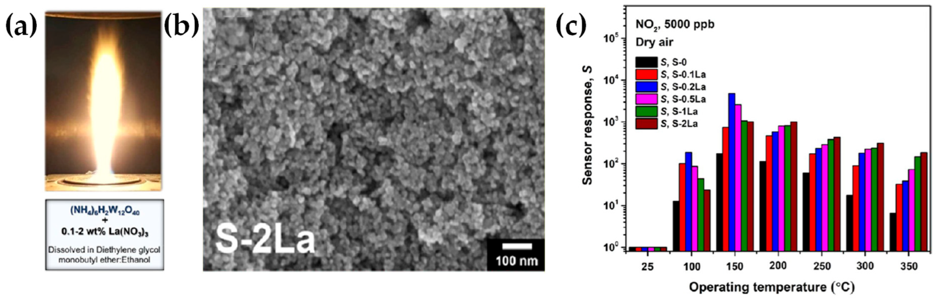
| La2O3–WO3 | Open flame FSP reactor, powder pasting, spin coating | Ammonium (meta) tungstate hydrate, La(III) nitrate hydrate | Diethylene glycol monobutyl ether, ethanol | 0.02 | 5 | 5 | NO2 | 5, 1, 0.05/ 150 °C | 7213.6, 1045.3, 15.2 | La2O3: 1–2, WO3: 5–20 | [242] |
| La1–xFeO3–δ with A-site deficiency | Enclosed-flame FSP reactor (pilot flame = CH4: 1.25, O2: 3.2, Ar: 5.0 L min−1), powder pasting, screen-printing | La nitrate, Fe nitrate | Absolute ethyl alcohol | 5 | CO2 | 10%/425 °C | 3.38 | <10 | [128] | ||
| Zn2SnO4 | Open flame FSP reactor, powder pasting, spin coating | Zn(II) acetylacetonate, Sn(II) 2-ethylhexanoate | Methanol, xylene | 0.5 | 5 | 5 | HCOOH | 1000, 50, 20/300 °C | 1829, 41.65, 10 | 5–25 | [243] |
3.8. FSP Nanostructures for Electrocatalytic and Energy Conversion Applications


4. Concluding Remarks—Future Perspectives
- (a)
- Multifunctionality Enhancement: As the title of this review suggests, multifunctionality is at the heart of FSP’s premise. Future advancements should emphasize developing processes that can fabricate nanostructures with an even broader range of functionalities, expanding their utility across diverse sectors. There is growing interest in the development of hybrid versions of FSP that incorporate additional physical processes, such as electric fields or ultrasound [258,259]. The integration of an electric field into the FSP process, for instance, could offer enhanced control over particle formation. By applying an electric field, it is possible to influence the charge distribution within the flame, potentially leading to more uniform particle sizes and shapes.
- (b)
- Technological Synergies: Harnessing the potential of complementary technologies, like AI and real-time monitoring tools, will trigger the era of “smart” FSP [260]. This would not only ensure the efficient production of desired nanostructures but might also open doors to materials previously deemed unattainable.
- (c)
- Economic Precursor Development: As FSP broadens its reach, the use of economical and readily available precursors will be essential. Research geared toward identifying and harnessing such materials will significantly reduce production costs, making FSP-synthesized nanoparticles more accessible.
- (d)
- Challenge Mitigation: While the review refers to the advancements, it is vital not to overlook the inherent challenges of FSP, be it in scalability, integration with standard fabrication environments, or ensuring the robustness of the nanostructures. Innovations addressing these challenges head-on will be instrumental in FSP’s widespread adoption.
- (e)
- Expanding Application Horizons: While FSP-derived nanoparticles have found their place in various applications, constant research is required to explore untapped potentials. Fields such as renewable energy, biomedicine, and advanced electronics may witness revolutionary products birthed from FSP advancements. Integrating biological components, such as enzymes or other organic molecules, into the FSP process might enable the synthesis of bio-functionalized nanoparticles. These could have specific applications in targeted drug delivery, biosensors, or bio-catalysis.
- (f)
- Environmental and Safety Concerns: As with all industrial processes, the environmental impact of FSP, along with safety concerns, will need continuous evaluation. Future iterations of FSP should aim for greener processes, ensuring sustainability.
Author Contributions
Funding
Data Availability Statement
Conflicts of Interest
References
- Meierhofer, F.; Fritsching, U. Synthesis of Metal Oxide Nanoparticles in Flame Sprays: Review on Process Technology, Modeling, and Diagnostics. Energy Fuels 2021, 35, 5495–5537. [Google Scholar] [CrossRef]
- Teoh, W.Y.; Amal, R.; Mädler, L. Flame Spray Pyrolysis: An Enabling Technology for Nanoparticles Design and Fabrication. Nanoscale 2010, 2, 1324–1347. [Google Scholar] [CrossRef] [PubMed]
- Ulrich, G.D. Special Report. Chem. Eng. News Arch. 1984, 62, 22–29. [Google Scholar] [CrossRef]
- Liu, S.; Mohammadi, M.M.; Swihart, M.T. Fundamentals and Recent Applications of Catalyst Synthesis Using Flame Aerosol Technology. Chem. Eng. J. 2021, 405, 126958. [Google Scholar] [CrossRef]
- Leskelä, M.; Ritala, M. Atomic Layer Deposition (ALD): From Precursors to Thin Film Structures. Thin Solid Films 2002, 409, 138–146. [Google Scholar] [CrossRef]
- George, S.M. Atomic Layer Deposition: An Overview. Chem. Rev. 2010, 110, 111–131. [Google Scholar] [CrossRef] [PubMed]
- Karthikeyan, J.; Berndt, C.C.; Tikkanen, J.; Wang, J.Y.; King, A.H.; Herman, H. Nanomaterial Powders and Deposits Prepared by Flame Spray Processing of Liquid Precursors. Nanostructured Mater. 1997, 8, 61–74. [Google Scholar] [CrossRef]
- Cai, Z.; Liu, B.; Zou, X.; Cheng, H.-M. Chemical Vapor Deposition Growth and Applications of Two-Dimensional Materials and Their Heterostructures. Chem. Rev. 2018, 118, 6091–6133. [Google Scholar] [CrossRef]
- Sun, L.; Yuan, G.; Gao, L.; Yang, J.; Chhowalla, M.; Gharahcheshmeh, M.H.; Gleason, K.K.; Choi, Y.S.; Hong, B.H.; Liu, Z. Chemical Vapour Deposition. Nat. Rev. Methods Primers 2021, 1, 5. [Google Scholar] [CrossRef]
- Hench, L.L.; West, J.K. The Sol-Gel Process. Chem. Rev. 1990, 90, 33–72. [Google Scholar] [CrossRef]
- Danks, A.E.; Hall, S.R.; Schnepp, Z.J.M.H. The Evolution of ‘Sol–Gel’ Chemistry as a Technique for Materials Synthesis. Mater. Horiz. 2016, 3, 91–112. [Google Scholar] [CrossRef]
- Byrappa, K.; Adschiri, T. Hydrothermal Technology for Nanotechnology. Prog. Cryst. Growth Charact. Mater. 2007, 53, 117–166. [Google Scholar] [CrossRef]
- Rabenau, A. The Role of Hydrothermal Synthesis in Preparative Chemistry. Angew. Chem. Int. Ed. Engl. 1985, 24, 1026–1040. [Google Scholar] [CrossRef]
- Hess, D.W. Plasma-enhanced CVD: Oxides, Nitrides, Transition Metals, and Transition Metal Silicides. J. Vac. Sci. Technol. A 1984, 2, 244–252. [Google Scholar] [CrossRef]
- Vasudev, M.C.; Anderson, K.D.; Bunning, T.J.; Tsukruk, V.V.; Naik, R.R. Exploration of Plasma-Enhanced Chemical Vapor Deposition as a Method for Thin-Film Fabrication with Biological Applications. ACS Appl. Mater. Interfaces 2013, 5, 3983–3994. [Google Scholar] [CrossRef] [PubMed]
- Bhardwaj, N.; Kundu, S.C. Electrospinning: A Fascinating Fiber Fabrication Technique. Biotechnol. Adv. 2010, 28, 325–347. [Google Scholar] [CrossRef] [PubMed]
- Teo, W.E.; Ramakrishna, S. A Review on Electrospinning Design and Nanofibre Assemblies. Nanotechnology 2006, 17, R89. [Google Scholar] [CrossRef]
- Zeng, H.; Du, X.-W.; Singh, S.C.; Kulinich, S.A.; Yang, S.; He, J.; Cai, W. Nanomaterials via Laser Ablation/Irradiation in Liquid: A Review. Adv. Funct. Mater. 2012, 22, 1333–1353. [Google Scholar] [CrossRef]
- Kim, M.; Osone, S.; Kim, T.; Higashi, H.; Seto, T. Synthesis of Nanoparticles by Laser Ablation: A Review. KONA Powder Part J. 2017, 34, 80–90. [Google Scholar] [CrossRef]
- Jansson, U.; Lewin, E. Sputter Deposition of Transition-Metal Carbide Films—A Critical Review from a Chemical Perspective. Thin Solid Films 2013, 536, 1–24. [Google Scholar] [CrossRef]
- Thornton, J.A. The Microstructure of Sputter-deposited Coatings. J. Vac. Sci. Technol. A 1986, 4, 3059–3065. [Google Scholar] [CrossRef]
- Nüchter, M.; Ondruschka, B.; Bonrath, W.; Gum, A. Microwave Assisted Synthesis—A Critical Technology Overview. Green Chem. 2004, 6, 128–141. [Google Scholar] [CrossRef]
- Lidström, P.; Tierney, J.; Wathey, B.; Westman, J. Microwave Assisted Organic Synthesis—A Review. Tetrahedron 2001, 57, 9225–9283. [Google Scholar] [CrossRef]
- Malekzadeh, M.; Swihart, M.T. Vapor-Phase Production of Nanomaterials. Chem. Soc. Rev. 2021, 50, 7132–7249. [Google Scholar] [CrossRef]
- Rsanchez. Technology Readiness Assessment Guide—DOE Directives, Guidance, and Delegations. Available online: https://www.directives.doe.gov/directives-documents/400-series/0413.3-EGuide-04a (accessed on 25 October 2023).
- Workie, A.B.; Ningsih, H.S.; Shih, S.-J. An Comprehensive Review on the Spray Pyrolysis Technique: Historical Context, Operational Factors, Classifications, and Product Applications. J. Anal. Appl. Pyrolysis 2023, 170, 105915. [Google Scholar] [CrossRef]
- Teoh, W. A Perspective on the Flame Spray Synthesis of Photocatalyst Nanoparticles. Materials 2013, 6, 3194–3212. [Google Scholar] [CrossRef] [PubMed]
- Strobel, R.; Pratsinis, S.E. Flame Aerosol Synthesis of Smart Nanostructured Materials. J. Mater. Chem. 2007, 17, 4743. [Google Scholar] [CrossRef]
- CRC. Handbook of Chemistry and Physics, 95th ed.; Haynes, W.M., Ed.; CRC Press: Boca Raton, FL, USA, 2014; ISBN 978-1-4822-0867-2. [Google Scholar]
- Sokolowski, M.; Sokolowska, A.; Michalski, A.; Gokieli, B. The “in-Flame-Reaction” Method for Al2O3 Aerosol Formation. J. Aerosol Sci. 1977, 8, 219–230. [Google Scholar] [CrossRef]
- Bickmore, C.R.; Waldner, K.F.; Treadwell, D.R.; Laine, R.M. Ultrafine Spinel Powders by Flame Spray Pyrolysis of a Magnesium Aluminum Double Alkoxide. J. Am. Ceram. Soc. 1996, 79, 1419–1423. [Google Scholar] [CrossRef]
- Tikkanen, J.; Gross, K.A.; Berndt, C.C.; Pitkänen, V.; Keskinen, J.; Raghu, S.; Rajala, M.; Karthikeyan, J. Characteristics of the Liquid Flame Spray Process. Surf. Coat. Technol. 1997, 90, 210–216. [Google Scholar] [CrossRef]
- Mädler, L.; Kammler, H.K.; Mueller, R.; Pratsinis, S.E. Controlled Synthesis of Nanostructured Particles by Flame Spray Pyrolysis. J. Aerosol Sci. 2002, 33, 369–389. [Google Scholar] [CrossRef]
- Mädler, L. Liquid-Fed Aerosol Reactors for One-Step Synthesis of Nano-Structured Particles. KONA Powder Part. J. 2004, 22, 107–120. [Google Scholar] [CrossRef]
- Camenzind, A.; Caseri, W.R.; Pratsinis, S.E. Flame-Made Nanoparticles for Nanocomposites. Nano Today 2010, 5, 48–65. [Google Scholar] [CrossRef]
- Sotiriou, G.A. Biomedical Applications of Multifunctional Plasmonic Nanoparticles. WIREs Nanomed. Nanobiotechnol. 2013, 5, 19–30. [Google Scholar] [CrossRef] [PubMed]
- Koirala, R.; Pratsinis, S.E.; Baiker, A. Synthesis of Catalytic Materials in Flames: Opportunities and Challenges. Chem. Soc. Rev. 2016, 45, 3053–3068. [Google Scholar] [CrossRef] [PubMed]
- Li, S.; Ren, Y.; Biswas, P.; Tse, S.D. Flame Aerosol Synthesis of Nanostructured Materials and Functional Devices: Processing, Modeling, and Diagnostics. Prog. Energy Combust. Sci. 2016, 55, 1–59. [Google Scholar] [CrossRef]
- Schneider, F.; Suleiman, S.; Menser, J.; Borukhovich, E.; Wlokas, I.; Kempf, A.; Wiggers, H.; Schulz, C. SpraySyn—A Standardized Burner Configuration for Nanoparticle Synthesis in Spray Flames. Rev. Sci. Instrum. 2019, 90, 085108. [Google Scholar] [CrossRef]
- Pokhrel, S.; Mädler, L. Flame-Made Particles for Sensors, Catalysis, and Energy Storage Applications. Energy Fuels 2020, 34, 13209–13224. [Google Scholar] [CrossRef]
- Venkatesan, S.; Mitzel, J.; Wegner, K.; Costa, R.; Gazdzicki, P.; Friedrich, K.A. Nanomaterials and Films for Polymer Electrolyte Membrane Fuel Cells and Solid Oxide Cells by Flame Spray Pyrolysis. Renew. Sustain. Energy Rev. 2022, 158, 112080. [Google Scholar] [CrossRef]
- Tran-Phu, T.; Daiyan, R.; Ta, X.M.C.; Amal, R.; Tricoli, A. From Stochastic Self-Assembly of Nanoparticles to Nanostructured (Photo)Electrocatalysts for Renewable Power-to-X Applications via Scalable Flame Synthesis. Adv. Funct. Mater. 2022, 32, 2110020. [Google Scholar] [CrossRef]
- John, A.T.; Tricoli, A. Flame Assisted Synthesis of Nanostructures for Device Applications. Adv. Phys. X 2022, 7, 1997153. [Google Scholar] [CrossRef]
- Grass, R.N.; Stark, W.J.; Athanassiou, E.-K. Reducing Flame Spray Pyrolysis Method for the Production of Metal, Non-Oxidic, Ceramic and Reduced Metal Oxide Powders and Nano-Powders, European Patent Office. European Patent EP1760043A1, 7 March 2007. [Google Scholar]
- Grass, R.N.; Albrecht, T.F.; Krumeich, F.; Stark, W.J. Large-Scale Preparation of Ceria/Bismuth Metal-Matrix Nano-Composites with a Hardness Comparable to Steel. J. Mater. Chem. 2007, 17, 1485. [Google Scholar] [CrossRef]
- Grass, R.N.; Stark, W.J. Flame Spray Synthesis under a Non-Oxidizing Atmosphere: Preparation of Metallic Bismuth Nanoparticles and Nanocrystalline Bulk Bismuth Metal. J. Nanopart. Res. 2006, 8, 729–736. [Google Scholar] [CrossRef]
- Athanassiou, E.K.; Grass, R.N.; Stark, W.J. Large-Scale Production of Carbon-Coated Copper Nanoparticles for Sensor Applications. Nanotechnology 2006, 17, 1668–1673. [Google Scholar] [CrossRef] [PubMed]
- Grass, R.N.; Athanassiou, E.K.; Stark, W.J. Covalently Functionalized Cobalt Nanoparticles as a Platform for Magnetic Separations in Organic Synthesis. Angew. Chem. Int. Ed. 2007, 46, 4909–4912. [Google Scholar] [CrossRef] [PubMed]
- Athanassiou, E.K.; Grass, R.N.; Osterwalder, N.; Stark, W.J. Preparation of Homogeneous, Bulk Nanocrystalline Ni/Mo Alloys with Tripled Vickers Hardness Using Flame-Made Metal Nanoparticles. Chem. Mater. 2007, 19, 4847–4854. [Google Scholar] [CrossRef]
- Athanassiou, E.K.; Grass, R.N.; Stark, W.J. One-Step Large Scale Gas Phase Synthesis of Mn2+ Doped ZnS Nanoparticles in Reducing Flames. Nanotechnology 2010, 21, 215603. [Google Scholar] [CrossRef] [PubMed]
- Strobel, R.; Pratsinis, S.E. Direct Synthesis of Maghemite, Magnetite and Wustite Nanoparticles by Flame Spray Pyrolysis. Adv. Powder Technol. 2009, 20, 190–194. [Google Scholar] [CrossRef]
- Kumfer, B.M.; Shinoda, K.; Jeyadevan, B.; Kennedy, I.M. Gas-Phase Flame Synthesis and Properties of Magnetic Iron Oxide Nanoparticles with Reduced Oxidation State. J. Aerosol Sci. 2010, 41, 257–265. [Google Scholar] [CrossRef]
- Kumfer, B.M.; Skeen, S.A.; Axelbaum, R.L. Soot Inception Limits in Laminar Diffusion Flames with Application to Oxy–Fuel Combustion. Combust. Flame 2008, 154, 546–556. [Google Scholar] [CrossRef]
- Deligiannakis, Y.; Mantzanis, A.; Zindrou, A.; Smykala, S.; Solakidou, M. Control of Monomeric Vo’s versus Vo Clusters in ZrO2−x for Solar-Light H2 Production from H2O at High-Yield (millimoles gr−1 h−1). Sci. Rep. 2022, 12, 15132. [Google Scholar] [CrossRef] [PubMed]
- Zindrou, A.; Belles, L.; Solakidou, M.; Boukos, N.; Deligiannakis, Y. Non-Graphitized Carbon/Cu2O/Cu0 Nanohybrids with Improved Stability and Enhanced Photocatalytic H2 Production. Sci. Rep. 2023, 13, 13999. [Google Scholar] [CrossRef] [PubMed]
- Zindrou, A.; Deligiannakis, Y. Quantitative In Situ Monitoring of Cu-Atom Release by Cu2O Nanocatalysts under Photocatalytic CO2 Reduction Conditions: New Insights into the Photocorrosion Mechanism. Nanomaterials 2023, 13, 1773. [Google Scholar] [CrossRef] [PubMed]
- Grass, R.N.; Stark, W.J. Gas Phase Synthesis of Fcc-Cobalt Nanoparticles. J. Mater. Chem. 2006, 16, 1825. [Google Scholar] [CrossRef]
- Psathas, P.; Zindrou, A.; Papachristodoulou, C.; Boukos, N.; Deligiannakis, Y. In Tandem Control of La-Doping and CuO-Heterojunction on SrTiO3 Perovskite by Double-Nozzle Flame Spray Pyrolysis: Selective H2 vs. CH4 Photocatalytic Production from H2O/CH3OH. Nanomaterials 2023, 13, 482. [Google Scholar] [CrossRef] [PubMed]
- Strobel, R.; Mädler, L.; Piacentini, M.; Maciejewski, M.; Baiker, A.; Pratsinis, S.E. Two-Nozzle Flame Synthesis of Pt/Ba/Al2O3 for NOx Storage. Chem. Mater. 2006, 18, 2532–2537. [Google Scholar] [CrossRef]
- Minnermann, M.; Grossmann, H.K.; Pokhrel, S.; Thiel, K.; Hagelin-Weaver, H.; Bäumer, M.; Mädler, L. Double Flame Spray Pyrolysis as a Novel Technique to Synthesize Alumina-Supported Cobalt Fischer–Tropsch Catalysts. Catal. Today 2013, 214, 90–99. [Google Scholar] [CrossRef]
- Høj, M.; Pham, D.K.; Brorson, M.; Mädler, L.; Jensen, A.D.; Grunwaldt, J.-D. Two-Nozzle Flame Spray Pyrolysis (FSP) Synthesis of CoMo/Al2O3 Hydrotreating Catalysts. Catal. Lett. 2013, 143, 386–394. [Google Scholar] [CrossRef]
- Schubert, M.; Pokhrel, S.; Thomé, A.; Zielasek, V.; Gesing, T.M.; Roessner, F.; Mädler, L.; Bäumer, M. Highly Active Co–Al2O3 -Based Catalysts for CO2 Methanation with Very Low Platinum Promotion Prepared by Double Flame Spray Pyrolysis. Catal. Sci. Technol. 2016, 6, 7449–7460. [Google Scholar] [CrossRef]
- Horlyck, J.; Pokhrel, S.; Lovell, E.; Bedford, N.M.; Mädler, L.; Amal, R.; Scott, J. Unifying Double Flame Spray Pyrolysis with Lanthanum Doping to Restrict Cobalt–Aluminate Formation in Co/Al2O3 Catalysts for the Dry Reforming of Methane. Catal. Sci. Technol. 2019, 9, 4970–4980. [Google Scholar] [CrossRef]
- Stahl, J.; Ilsemann, J.; Pokhrel, S.; Schowalter, M.; Tessarek, C.; Rosenauer, A.; Eickhoff, M.; Bäumer, M.; Mädler, L. Comparing Co-catalytic Effects of ZrOx, SmOx, and Pt on COx Methanation over Co-based Catalysts Prepared by Double Flame Spray Pyrolysis. ChemCatChem 2021, 13, 2815–2831. [Google Scholar] [CrossRef]
- Gäßler, M.; Stahl, J.; Schowalter, M.; Pokhrel, S.; Rosenauer, A.; Mädler, L.; Güttel, R. The Impact of Support Material of Cobalt-Based Catalysts Prepared by Double Flame Spray Pyrolysis on CO2 Methanation Dynamics. ChemCatChem 2022, 14, e202200286. [Google Scholar] [CrossRef]
- Henning, D.F.; Merkl, P.; Yun, C.; Iovino, F.; Xie, L.; Mouzourakis, E.; Moularas, C.; Deligiannakis, Y.; Henriques-Normark, B.; Leifer, K.; et al. Luminescent CeO2:Eu3+ Nanocrystals for Robust in Situ H2O2 Real-Time Detection in Bacterial Cell Cultures. Biosens. Bioelectron. 2019, 132, 286–293. [Google Scholar] [CrossRef]
- Grossmann, H.K.; Grieb, T.; Meierhofer, F.; Hodapp, M.J.; Noriler, D.; Gröhn, A.; Meier, H.F.; Fritsching, U.; Wegner, K.; Mädler, L. Nanoscale Mixing during Double-Flame Spray Synthesis of Heterostructured Nanoparticles. J. Nanopart. Res. 2015, 17, 174. [Google Scholar] [CrossRef]
- Solakidou, M.; Georgiou, Y.; Deligiannakis, Y. Double-Nozzle Flame Spray Pyrolysis as a Potent Technology to Engineer Noble Metal-TiO2 Nanophotocatalysts for Efficient H2 Production. Energies 2021, 14, 817. [Google Scholar] [CrossRef]
- Tada, S.; Larmier, K.; Büchel, R.; Copéret, C. Methanol Synthesis via CO2 Hydrogenation over CuO–ZrO2 Prepared by Two-Nozzle Flame Spray Pyrolysis. Catal. Sci. Technol. 2018, 8, 2056–2060. [Google Scholar] [CrossRef]
- Li, H.; Erinmwingbovo, C.; Birkenstock, J.; Schowalter, M.; Rosenauer, A.; La Mantia, F.; Mädler, L.; Pokhrel, S. Double Flame-Fabricated High-Performance AlPO4/LiMn2O4 Cathode Material for Li-Ion Batteries. ACS Appl. Energy Mater. 2021, 4, 4428–4443. [Google Scholar] [CrossRef]
- Lovell, E.C.; Großman, H.; Horlyck, J.; Scott, J.; Mädler, L.; Amal, R. Asymmetrical Double Flame Spray Pyrolysis-Designed SiO2/Ce0.7Zr0.3O2 for the Dry Reforming of Methane. ACS Appl. Mater. Interfaces 2019, 11, 25766–25777. [Google Scholar] [CrossRef]
- Psathas, P.; Moularas, C.; Smykała, S.; Deligiannakis, Y. Highly Crystalline Nanosized NaTaO3/NiO Heterojunctions Engineered by Double-Nozzle Flame Spray Pyrolysis for Solar-to-H2 Conversion: Toward Industrial-Scale Synthesis. ACS Appl. Nano Mater. 2023, 6, 2658–2671. [Google Scholar] [CrossRef]
- Gockeln, M.; Pokhrel, S.; Meierhofer, F.; Glenneberg, J.; Schowalter, M.; Rosenauer, A.; Fritsching, U.; Busse, M.; Mädler, L.; Kun, R. Fabrication and Performance of Li4Ti5O12/C Li-Ion Battery Electrodes Using Combined Double Flame Spray Pyrolysis and Pressure-Based Lamination Technique. J. Power Sources 2018, 374, 97–106. [Google Scholar] [CrossRef]
- Hansen, J.P.; Jensen, J.R.; Livbjerg, H.; Johannessen, T. Synthesis of ZnO Particles in a Quench-Cooled Flame Reactor. AIChE J. 2001, 47, 2413–2418. [Google Scholar] [CrossRef]
- Teleki, A.; Heine, M.C.; Krumeich, F.; Akhtar, M.K.; Pratsinis, S.E. In Situ Coating of Flame-Made TiO2 Particles with Nanothin SiO2 Films. Langmuir 2008, 24, 12553–12558. [Google Scholar] [CrossRef] [PubMed]
- Teleki, A.; Pratsinis, S.E.; Wegner, K.; Jossen, R.; Krumeich, F. Flame-Coating of Titania Particles with Silica. J. Mater. Res. 2005, 20, 1336–1347. [Google Scholar] [CrossRef]
- Teleki, A.; Buesser, B.; Heine, M.C.; Krumeich, F.; Akhtar, M.K.; Pratsinis, S.E. Role of Gas−Aerosol Mixing during in Situ Coating of Flame-Made Titania Particles. Ind. Eng. Chem. Res. 2009, 48, 85–92. [Google Scholar] [CrossRef]
- Sotiriou, G.A.; Sannomiya, T.; Teleki, A.; Krumeich, F.; Vörös, J.; Pratsinis, S.E. Non-Toxic Dry-Coated Nanosilver for Plasmonic Biosensors. Adv. Funct. Mater. 2010, 20, 4250–4257. [Google Scholar] [CrossRef] [PubMed]
- Sotiriou, G.; Gass, S.; Pratsinis, S.E. Hermetically Coated Nanosilver: No Ag+ Ion Leaching. MRS Proc. 2012, 1386, mrsf11-1386-d09-24. [Google Scholar] [CrossRef]
- Moularas, C.; Georgiou, Y.; Adamska, K.; Deligiannakis, Y. Thermoplasmonic Heat Generation Efficiency by Nonmonodisperse Core–Shell Ag0@SiO2 Nanoparticle Ensemble. J. Phys. Chem. C 2019, 123, 22499–22510. [Google Scholar] [CrossRef]
- Moularas, C.; Dimitriou, C.; Georgiou, Y.; Evangelakis, G.; Boukos, N.; Deligiannakis, Y. Electron Paramagnetic Resonance Quantifies Hot-Electron Transfer from Plasmonic Ag@SiO2 to Cr6+/Cr5+/Cr3+. J. Phys. Chem. C 2023, 127, 2045–2057. [Google Scholar] [CrossRef]
- Fragou, F.; Stathi, P.; Deligiannakis, Y.; Louloudi, M. Safe-by-Design Flame Spray Pyrolysis of SiO2 Nanostructures for Minimizing Acute Toxicity. ACS Appl. Nano Mater. 2022, 5, 8184–8195. [Google Scholar] [CrossRef]
- Li, Y.; Hu, Y.; Huo, J.; Jiang, H.; Li, C.; Huang, G. Stable Core Shell Co3Fe7–CoFe2O4 Nanoparticles Synthesized via Flame Spray Pyrolysis Approach. Ind. Eng. Chem. Res. 2012, 51, 11157–11162. [Google Scholar] [CrossRef]
- Jeanne-Rose, V.; Samain, H.; Deligiannakis, Y.; Louloudi, M. Metal Oxide Particles Coated with a Rare-Earth Oxide and Process for Preparing Same by Flame Spray Pyrolysis. U.S. Patent 17/789,501, 9 February 2023. [Google Scholar]
- Zhou, G.; Zhang, Y.; Zhao, X.; Gui, Y.; Wang, X.; Li, L.; Chen, T.; Huang, Z.; Lin, H. FSP Synthesized Core-Shell CuOx@SiO2 Catalyst with Excellent Thermal Stability for Catalytic Combustion of Ammonia. Fuel 2023, 334, 126824. [Google Scholar] [CrossRef]
- Wu, Z.; Zhang, Y.; Zhao, X.; Wang, H.; Li, S. Dual Liquid/Vapor-Fed Flame Synthesis for the Effective Preparation of SiO2@YAlO3:Nd3+ Nanophosphors. Proc. Combust. Inst. 2021, 38, 1299–1307. [Google Scholar] [CrossRef]
- Sotiriou, G.A.; Schneider, M.; Pratsinis, S.E. Green, Silica-Coated Monoclinic Y2O3:Tb3+ Nanophosphors: Flame Synthesis and Characterization. J. Phys. Chem. C 2012, 116, 4493–4499. [Google Scholar] [CrossRef] [PubMed]
- Sotiriou, G.A.; Blattmann, C.O.; Deligiannakis, Y. Nanoantioxidant-Driven Plasmon Enhanced Proton-Coupled Electron Transfer. Nanoscale 2016, 8, 796–803. [Google Scholar] [CrossRef] [PubMed]
- Sahm, T.; Rong, W.; Barsan, N.; Madler, L.; Weimar, U. Sensing of CH4, CO and Ethanol with in Situ Nanoparticle Aerosol-Fabricated Multilayer Sensors. Sens. Actuators B Chem. 2007, 127, 63–68. [Google Scholar] [CrossRef]
- Sahm, T.; Rong, W.; Bârsan, N.; Mädler, L.; Friedlander, S.K.; Weimar, U. Formation of Multilayer Films for Gas Sensing by in Situ Thermophoretic Deposition of Nanoparticles from Aerosol Phase. J. Mater. Res. 2007, 22, 850–857. [Google Scholar] [CrossRef]
- Deligiannakis, Y.; Tsikourkitoudi, V.; Stathi, P.; Wegner, K.; Papavasiliou, J.; Louloudi, M. PdO/Pd0/TiO2 Nanocatalysts Engineered by Flame Spray Pyrolysis: Study of the Synergy of PdO/Pd0 on H2 Production by HCOOH Dehydrogenation and the Deactivation Mechanism. Energy Fuels 2020, 34, 15026–15038. [Google Scholar] [CrossRef]
- Mädler, L.; Roessler, A.; Pratsinis, S.E.; Sahm, T.; Gurlo, A.; Barsan, N.; Weimar, U. Direct Formation of Highly Porous Gas-Sensing Films by in Situ Thermophoretic Deposition of Flame-Made Pt/SnO2 Nanoparticles. Sens. Actuators B Chem. 2006, 114, 283–295. [Google Scholar] [CrossRef]
- Nasiri, N.; Bo, R.; Wang, F.; Fu, L.; Tricoli, A. Ultraporous Electron-Depleted ZnO Nanoparticle Networks for Highly Sensitive Portable Visible-Blind UV Photodetectors. Adv. Mater. 2015, 27, 4336–4343. [Google Scholar] [CrossRef]
- Chen, H.; Mulmudi, H.K.; Tricoli, A. Flame Spray Pyrolysis for the One-Step Fabrication of Transition Metal Oxide Films: Recent Progress in Electrochemical and Photoelectrochemical Water Splitting. Chin. Chem. Lett. 2020, 31, 601–604. [Google Scholar] [CrossRef]
- Mane, R.S.; Lokhande, C.D. Chemical Deposition Method for Metal Chalcogenide Thin Films. Mater. Chem. Phys. 2000, 65, 1–31. [Google Scholar] [CrossRef]
- Kavitha, R.; Meghani, S.; Jayaram, V. Synthesis of Titania Films by Combustion Flame Spray Pyrolysis Technique and Its Characterization for Photocatalysis. Mater. Sci. Eng. B 2007, 139, 134–140. [Google Scholar] [CrossRef]
- Kavitha, R.; Hegde, S.R.; Jayaram, V. Oxide Films by Combustion Pyrolysis of Solution Precursors. Mater. Sci. Eng. A 2003, 359, 18–23. [Google Scholar] [CrossRef]
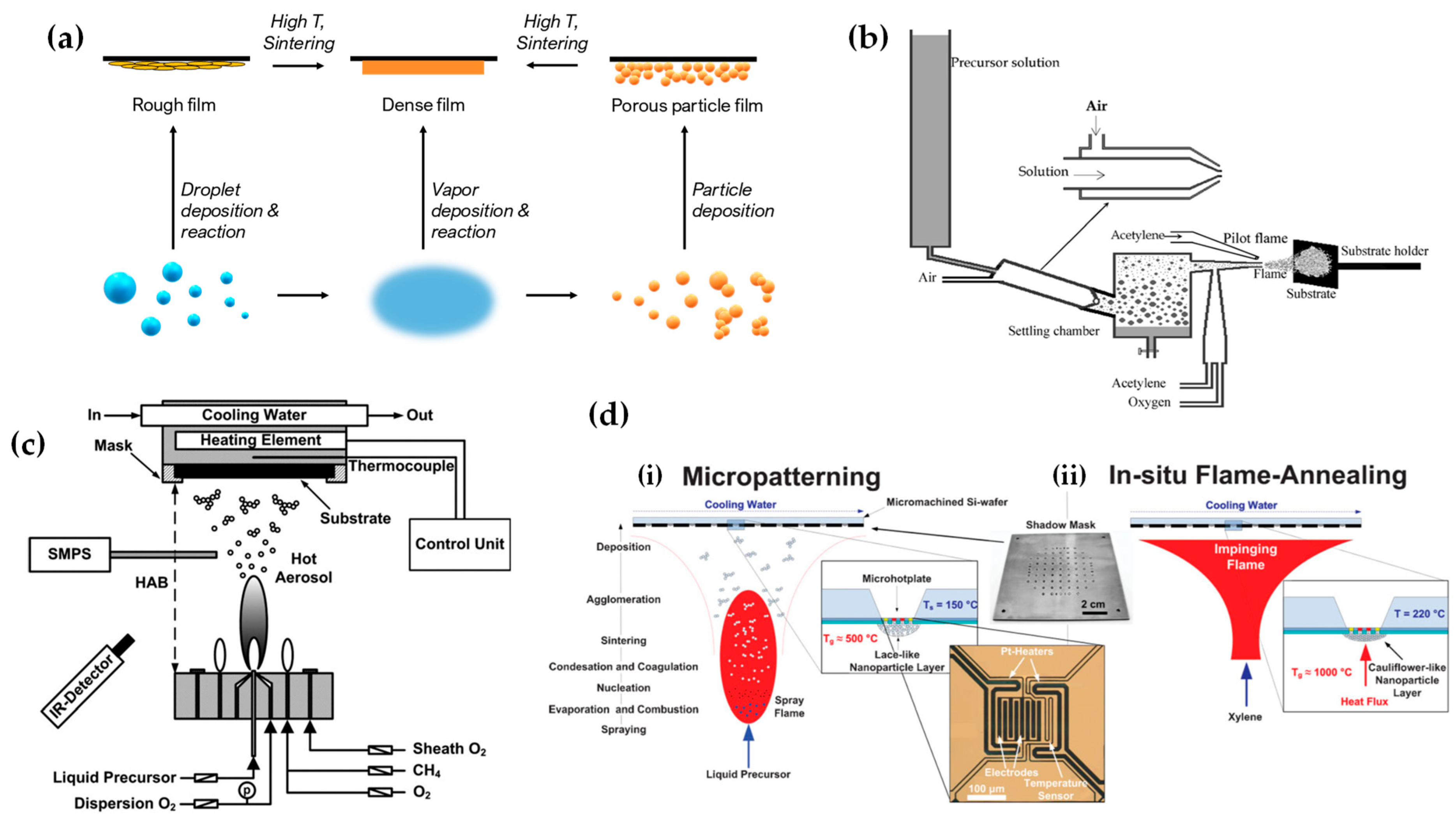
- Tricoli, A.; Elmøe, T.D. Flame Spray Pyrolysis Synthesis and Aerosol Deposition of Nanoparticle Films. AIChE J. 2012, 58, 3578–3588. [Google Scholar] [CrossRef]
- Tricoli, A.; Graf, M.; Mayer, F.; Kuühne, S.; Hierlemann, A.; Pratsinis, S.E. Micropatterning Layers by Flame Aerosol Deposition-Annealing. Adv. Mater. 2008, 20, 3005–3010. [Google Scholar] [CrossRef]
- Salameh, S.; Gómez-Hernández, J.; Goulas, A.; Van Bui, H.; van Ommen, J.R. Advances in Scalable Gas-Phase Manufacturing and Processing of Nanostructured Solids: A Review. Particuology 2017, 30, 15–39. [Google Scholar] [CrossRef]
- Available online: https://www.Cabotcorp.Com/Solutions#products-Plus (accessed on 5 November 2023).
- Available online: https://Corporate.Evonik.Com/En/Products-and-Solutions/Markets (accessed on 5 November 2023).
- Kelesidis, G.A.; Pratsinis, S.E. A Perspective on Gas-Phase Synthesis of Nanomaterials: Process Design, Impact and Outlook. Chem. Eng. J. 2021, 421, 129884. [Google Scholar] [CrossRef]
- Available online: https://www.Hemotune.Ch/Technology (accessed on 5 November 2023).
- Available online: https://www.Turbobeads.Com (accessed on 5 November 2023).
- Available online: https://www.Heiq.Com/Products/ (accessed on 5 November 2023).
- Sotiris, E.P.; Height, M. Antimicrobial and Antifungal Powders Made by Flame Spray Pyrolysis. U.S. Patent Application 11/884,039, 10 December 2008. [Google Scholar]
- Wegner, K.; Schimmöller, B.; Thiebaut, B.; Fernandez, C.; Rao, T.N. Pilot Plants for Industrial Nanoparticle Production by Flame Spray Pyrolysis. KONA 2011, 29, 251–265. [Google Scholar] [CrossRef]
- Gerken, L.R.H.; Neuer, A.L.; Gschwend, P.M.; Keevend, K.; Gogos, A.; Anthis, A.H.C.; Aengenheister, L.; Pratsinis, S.E.; Plasswilm, L.; Herrmann, I.K. Scalable Synthesis of Ultrasmall Metal Oxide Radio-Enhancers Outperforming Gold. Chem. Mater. 2021, 33, 3098–3112. [Google Scholar] [CrossRef]
- Mädler, L.; Stark, W.J.; Pratsinis, S.E. Flame-Made Ceria Nanoparticles. J. Mater. Res. 2002, 17, 1356–1362. [Google Scholar] [CrossRef]
- Wegner, K.; Pratsinis, S.E. Gas-Phase Synthesis of Nanoparticles: Scale-up and Design of Flame Reactors. Powder Technol. 2005, 150, 117–122. [Google Scholar] [CrossRef]
- Wegner, K.; Pratsinis, S.E. Scale-up of Nanoparticle Synthesis in Diffusion Flame Reactors. Chem. Eng. Sci. 2003, 58, 4581–4589. [Google Scholar] [CrossRef]
- Akurati, K.K.; Vital, A.; Dellemann, J.-P.; Michalow, K.; Graule, T.; Ferri, D.; Baiker, A. Flame-Made WO3/TiO2 Nanoparticles: Relation between Surface Acidity, Structure and Photocatalytic Activity. Appl. Catal. B Environ. 2008, 79, 53–62. [Google Scholar] [CrossRef]
- Heel, A.; Holtappels, P.; Hug, P.; Graule, T. Flame Spray Synthesis of Nanoscale La0.6Sr0.4Co0.2Fe0.8O3−δ and Ba0.5Sr0.5Co0.8Fe0.2O3−δ as Cathode Materials for Intermediate Temperature Solid Oxide Fuel Cells. Fuel Cells 2010, 10, 419–432. [Google Scholar] [CrossRef]
- Mueller, R.; Mädler, L.; Pratsinis, S.E. Nanoparticle Synthesis at High Production Rates by Flame Spray Pyrolysis. Chem. Eng. Sci. 2003, 58, 1969–1976. [Google Scholar] [CrossRef]
- Mueller, R.; Jossen, R.; Pratsinis, S.E.; Watson, M.; Akhtar, M.K. Zirconia Nanoparticles Made in Spray Flames at High Production Rates. J. Am. Ceram. Soc. 2004, 87, 197–202. [Google Scholar] [CrossRef]
- Gröhn, A.J.; Pratsinis, S.E.; Sánchez-Ferrer, A.; Mezzenga, R.; Wegner, K. Scale-up of Nanoparticle Synthesis by Flame Spray Pyrolysis: The High-Temperature Particle Residence Time. Ind. Eng. Chem. Res. 2014, 53, 10734–10742. [Google Scholar] [CrossRef]
- Meierhofer, F.; Mädler, L.; Fritsching, U. Nanoparticle Evolution in Flame Spray Pyrolysis—Process Design via Experimental and Computational Analysis. AIChE J. 2020, 66, e16885. [Google Scholar] [CrossRef]
- Jossen, R.; Mueller, R.; Pratsinis, S.E.; Watson, M.; Akhtar, M.K. Morphology and Composition of Spray-Flame-Made Yttria-Stabilized Zirconia Nanoparticles. Nanotechnology 2005, 16, S609–S617. [Google Scholar] [CrossRef]
- Hembram, K.; Sivaprakasam, D.; Rao, T.N.; Wegner, K. Large-Scale Manufacture of ZnO Nanorods by Flame Spray Pyrolysis. J. Nanopart. Res. 2013, 15, 1461. [Google Scholar] [CrossRef]
- Betancur-Granados, N.; Pöllmann, H.; Restrepo-Baena, O.J.; Tobón, J.I. Nanosized Belite Phases Obtained by Flame Spray Pyrolysis: Assessment of Process Conditions on the Mineralogy and Reactivity. Cem. Concr. Res. 2023, 164, 107062. [Google Scholar] [CrossRef]
- Kho, Y.K.; Teoh, W.Y.; Iwase, A.; Mädler, L.; Kudo, A.; Amal, R. Flame Preparation of Visible-Light-Responsive BiVO4 Oxygen Evolution Photocatalysts with Subsequent Activation via Aqueous Route. ACS Appl. Mater. Interfaces 2011, 3, 1997–2004. [Google Scholar] [CrossRef] [PubMed]
- Stathi, P.; Solakidou, M.; Deligiannakis, Y. Lattice Defects Engineering in W-, Zr-Doped BiVO4 by Flame Spray Pyrolysis: Enhancing Photocatalytic O2 Evolution. Nanomaterials 2021, 11, 501. [Google Scholar] [CrossRef] [PubMed]
- Psathas, P.; Georgiou, Y.; Moularas, C.; Armatas, G.S.; Deligiannakis, Y. Controlled-Phase Synthesis of Bi2Fe4O9 & BiFeO3 by Flame Spray Pyrolysis and Their Evaluation as Non-Noble Metal Catalysts for Efficient Reduction of 4-Nitrophenol. Powder Technol. 2020, 368, 268–277. [Google Scholar] [CrossRef]
- Psathas, P.; Solakidou, M.; Mantzanis, A.; Deligiannakis, Y. Flame Spray Pyrolysis Engineering of Nanosized Mullite-Bi2Fe4O9 and Perovskite-BiFeO3 as Highly Efficient Photocatalysts for O2 Production from H2O Splitting. Energies 2021, 14, 5235. [Google Scholar] [CrossRef]
- Punginsang, M.; Wisitsoraat, A.; Tuantranont, A.; Phanichphant, S.; Liewhiran, C. Ultrafine Bi2WO6 Nanoparticles Prepared by Flame Spray Pyrolysis for Selective Acetone Gas-Sensing. Mater. Sci. Semicond. Process. 2019, 90, 263–275. [Google Scholar] [CrossRef]
- Xiao, B.; Jiao, A.; Zhang, Y.; Yang, L.; Zhao, X.; Wu, C.; Guo, D.; Zhan, R.; Lin, H. Mixed Potential Type Ammonia Sensor Using Fe-Substituted LaCoO3 Sensing Electrode Prepared by Flame Spray Pyrolysis. Sens. Actuators B Chem. 2021, 346, 130470. [Google Scholar] [CrossRef]
- Jiao, A.; Zhang, Y.; Yang, L.; Zhao, X.; Wu, C.; Chen, T.; Zhan, R.; Huang, Z.; Lin, H. Enhanced CO2 Response of La1−xFeO3−δ Perovskites with A-Site Deficiency Synthesized by Flame Spray Pyrolysis. Ceram. Int. 2023, 49, 591–599. [Google Scholar] [CrossRef]
- Yuan, X.; Meng, L.; Zheng, C.; Zhao, H. Deep Insight into the Mechanism of Catalytic Combustion of CO and CH4 over SrTi1− xBxO3 (B = Co, Fe, Mn, Ni, and Cu) Perovskite via Flame Spray Pyrolysis. ACS Appl. Mater. Interfaces 2021, 13, 52571–52587. [Google Scholar] [CrossRef]
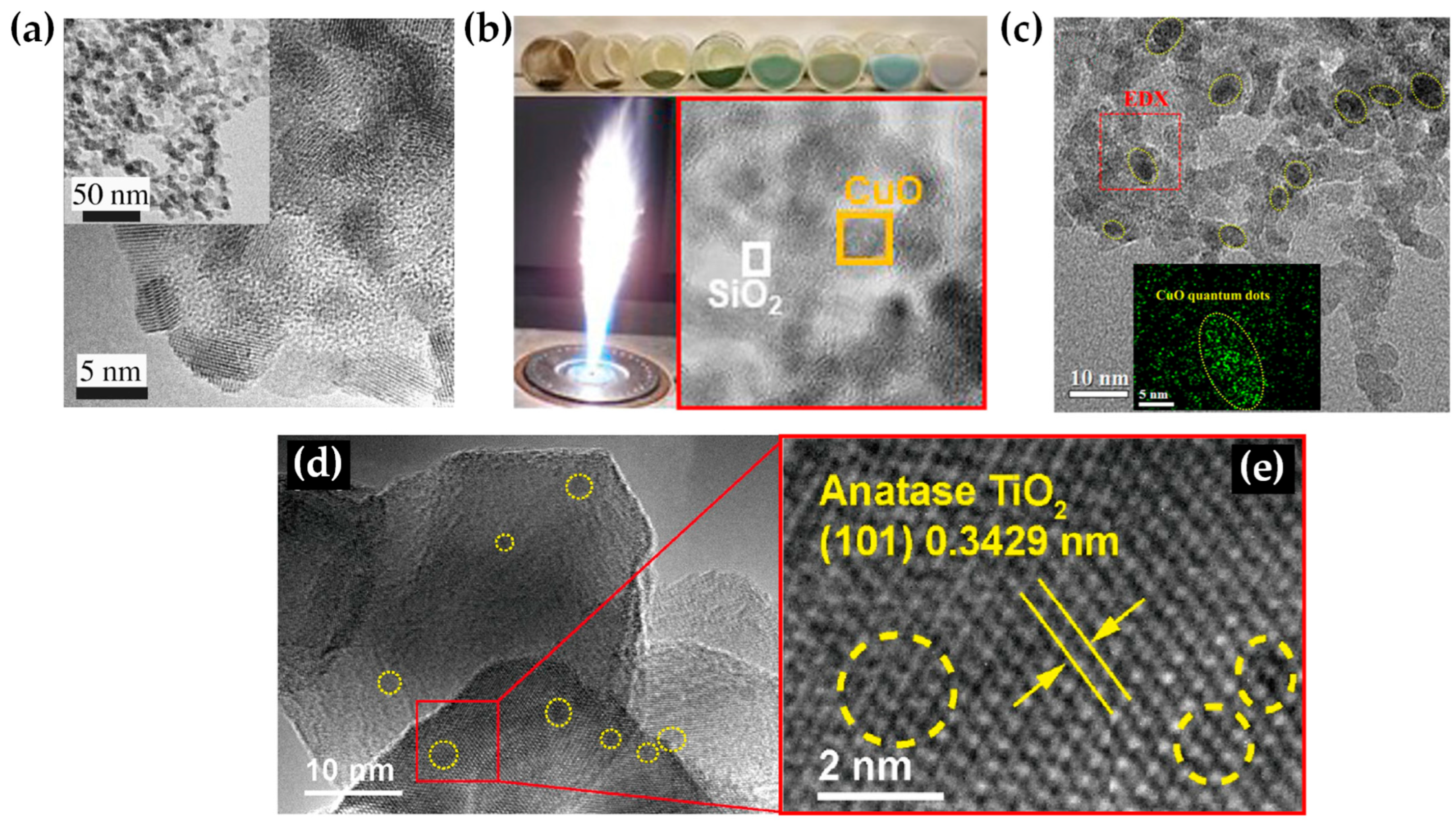
- Yuan, X.; Meng, L.; Xu, Z.; Zheng, C.; Zhao, H. CuO Quantum Dots Supported by SrTiO3 Perovskite Using the Flame Spray Pyrolysis Method: Enhanced Activity and Excellent Thermal Resistance for Catalytic Combustion of CO and CH4. Environ. Sci. Technol. 2021, 55, 14080–14086. [Google Scholar] [CrossRef]
- Yuan, X.; Zheng, C.; Zhang, T.; Li, L.; Yang, Q.; Zhao, H. Sodium Doped SrTi1−xBxO3 (B = Mn, Co) for Formaldehyde Catalytic Oxidation: Flame Spray Pyrolysis Fabrication and Reaction Mechanism Elaboration. Fuel Process. Technol. 2023, 247, 107763. [Google Scholar] [CrossRef]
- Moularas, C.; Psathas, P.; Deligiannakis, Y. Electron Paramagnetic Resonance Study of Photo-Induced Hole/Electron Pairs in NaTaO3 Nanoparticles. Chem. Phys. Lett. 2021, 782, 139031. [Google Scholar] [CrossRef]
- Kennedy, A.E.; Meekins, B.H. Combustion Synthesis and Photoelectrochemical Characterization of Gallium Zinc Oxynitrides. J. Mater. Res. 2018, 33, 3971–3978. [Google Scholar] [CrossRef]
- Huo, J.; Hu, Y.; Jiang, H.; Hou, X.; Li, C. Continuous Flame Synthesis of near Surface Nitrogen Doped TiO2 for Dye-Sensitized Solar Cells. Chem. Eng. J. 2014, 258, 163–170. [Google Scholar] [CrossRef]
- Bi, W.; Hu, Y.; Jiang, H.; Yu, H.; Li, W.; Li, C. In-Situ Synthesized Surface N-Doped Pt/TiO2 via Flame Spray Pyrolysis with Enhanced Thermal Stability for CO Catalytic Oxidation. Appl. Surf. Sci. 2019, 481, 360–368. [Google Scholar] [CrossRef]
- Boningari, T.; Inturi, S.N.R.; Suidan, M.; Smirniotis, P.G. Novel Continuous Single-Step Synthesis of Nitrogen-Modified TiO2 by Flame Spray Pyrolysis for Photocatalytic Degradation of Phenol in Visible Light. J. Mater. Sci. Technol. 2018, 34, 1494–1502. [Google Scholar] [CrossRef]
- Boningari, T.; Inturi, S.N.R.; Suidan, M.; Smirniotis, P.G. Novel One-Step Synthesis of Nitrogen-Doped TiO2 by Flame Aerosol Technique for Visible-Light Photocatalysis: Effect of Synthesis Parameters and Secondary Nitrogen (N) Source. Chem. Eng. J. 2018, 350, 324–334. [Google Scholar] [CrossRef]
- Smirniotis, P.G.; Boningari, T.; Damma, D.; Inturi, S.N.R. Single-Step Rapid Aerosol Synthesis of N-Doped TiO2 for Enhanced Visible Light Photocatalytic Activity. Catal. Commun. 2018, 113, 1–5. [Google Scholar] [CrossRef]
- Smirniotis, P.G.; Boningari, T.; Inturi, S.N.R. Single-Step Synthesis of N-Doped TiO2 by Flame Aerosol Method and the Effect of Synthesis Parameters. Aerosol Sci. Technol. 2018, 52, 913–922. [Google Scholar] [CrossRef]
- Herrmann, I.K.; Grass, R.N.; Mazunin, D.; Stark, W.J. Synthesis and Covalent Surface Functionalization of Nonoxidic Iron Core−Shell Nanomagnets. Chem. Mater. 2009, 21, 3275–3281. [Google Scholar] [CrossRef]
- Balakrishnan, A.; Groeneveld, J.D.; Pokhrel, S.; Mädler, L. Metal Sulfide Nanoparticles: Precursor Chemistry. Chem. Eur. J. 2021, 27, 6390–6406. [Google Scholar] [CrossRef] [PubMed]
- Bubenhofer, S.B.; Schumacher, C.M.; Koehler, F.M.; Luechinger, N.A.; Grass, R.N.; Stark, W.J. Large-Scale Synthesis of PbS–TiO2 Heterojunction Nanoparticles in a Single Step for Solar Cell Application. J. Phys. Chem. C 2012, 116, 16264–16270. [Google Scholar] [CrossRef]
- Pokhrel, S.; Stahl, J.; Groeneveld, J.D.; Schowalter, M.; Rosenauer, A.; Birkenstock, J.; Mädler, L. Flame Aerosol Synthesis of Metal Sulfides at High Temperature in Oxygen-Lean Atmosphere. Adv. Mater. 2023, 35, 2211104. [Google Scholar] [CrossRef] [PubMed]
- Grass, R.N.; Stark, W.J. Flame Synthesis of Calcium-, Strontium-, Barium Fluoride Nanoparticles and Sodium Chloride. Chem. Commun. 2005, 13, 1767–1769. [Google Scholar] [CrossRef] [PubMed]
- Stepuk, A.; Krämer, K.W.; Stark, W.J. Flame Synthesis of Complex Fluoride-Based Nanoparticles as Upconversion Phosphors. KONA Powder Part. J. 2013, 30, 267–275. [Google Scholar] [CrossRef][Green Version]
- Jodhani, G.; Mikaeili, F.; Gouma, P.I. Flame Spray Synthesis of VOPO4 Polymorphs. Front. Mater. 2019, 6, 254. [Google Scholar] [CrossRef]
- Rohner, F.; Ernst, F.O.; Arnold, M.; Hilbe, M.; Biebinger, R.; Ehrensperger, F.; Pratsinis, S.E.; Langhans, W.; Hurrell, R.F.; Zimmermann, M.B. Synthesis, Characterization, and Bioavailability in Rats of Ferric Phosphate Nanoparticles. J. Nutr. 2007, 137, 614–619. [Google Scholar] [CrossRef]
- Rudin, T.; Pratsinis, S.E. Homogeneous Iron Phosphate Nanoparticles by Combustion of Sprays. Ind. Eng. Chem. Res. 2012, 51, 7891–7900. [Google Scholar] [CrossRef][Green Version]
- Waser, O.; Büchel, R.; Hintennach, A.; Novák, P.; Pratsinis, S.E. Continuous Flame Aerosol Synthesis of Carbon-Coated Nano-LiFePO4 for Li-Ion Batteries. J. Aerosol Sci. 2011, 42, 657–667. [Google Scholar] [CrossRef]
- Badding, M.E.; Brown, J.L.; Fekety, C.R.; Song, Z. Corning Inc, Flame Spray Pyrolysis Method for Forming Nanoscale Lithium Metal Phosphate Powders. U.S. Patent 8,821,771, 3 April 2014. [Google Scholar]
- Cho, J.S.; Ko, Y.N.; Koo, H.Y.; Kang, Y.C. Synthesis of Nano-Sized Biphasic Calcium Phosphate Ceramics with Spherical Shape by Flame Spray Pyrolysis. J. Mater. Sci. Mater. Med. 2010, 21, 1143–1149. [Google Scholar] [CrossRef]
- Ataol, S.; Tezcaner, A.; Duygulu, O.; Keskin, D.; Machin, N.E. Synthesis and Characterization of Nanosized Calcium Phosphates by Flame Spray Pyrolysis, and Their Effect on Osteogenic Differentiation of Stem Cells. J. Nanopart. Res. 2015, 17, 95. [Google Scholar] [CrossRef]
- Tsikourkitoudi, V.; Karlsson, J.; Merkl, P.; Loh, E.; Henriques-Normark, B.; Sotiriou, G.A. Flame-Made Calcium Phosphate Nanoparticles with High Drug Loading for Delivery of Biologics. Molecules 2020, 25, 1747. [Google Scholar] [CrossRef] [PubMed]
- Huber, M.; Stark, W.J.; Loher, S.; Maciejewski, M.; Krumeich, F.; Baiker, A. Flame Synthesis of Calcium Carbonate Nanoparticles. Chem. Commun. 2005, 5, 648–650. [Google Scholar] [CrossRef] [PubMed]
- Strobel, R.; Maciejewski, M.; Pratsinis, S.E.; Baiker, A. Unprecedented Formation of Metastable Monoclinic BaCO3 Nanoparticles. Thermochim. Acta 2006, 445, 23–26. [Google Scholar] [CrossRef]
- Li, Y.; Hu, Y.; Huang, G.; Li, C. Metallic Iron Nanoparticles: Flame Synthesis, Characterization and Magnetic Properties. Particuology 2013, 11, 460–467. [Google Scholar] [CrossRef]
- Kang, Y.C.; Sohn, J.R.; Yoon, H.S.; Jung, K.Y.; Park, H.D. Improved Photoluminescence of Sr5(PO4)3Cl:Eu2+ Phosphor Particles Prepared by Flame Spray Pyrolysis. J. Electrochem. Soc. 2003, 150, H38. [Google Scholar] [CrossRef]
- Hilty, F.M.; Teleki, A.; Krumeich, F.; Büchel, R.; Hurrell, R.F.; Pratsinis, S.E.; Zimmermann, M.B. Development and Optimization of Iron- and Zinc-Containing Nanostructured Powders for Nutritional Applications. Nanotechnology 2009, 20, 475101. [Google Scholar] [CrossRef]
- Allen, L.; de Benoist, B.; Dary, O.; Hurrell, R. Guidelines on Food Fortification with Micronutrients; World Health Organization: Geneva, Switzerland; Food and Agriculture Organization of the United Nations: Rome, Italy, 2006; ISBN 978-92-4-159401-1. [Google Scholar]
- Yamada, A.; Chung, S.C.; Hinokuma, K. Optimized LiFePO4 for Lithium Battery Cathodes. J. Electrochem. Soc. 2001, 148, A224. [Google Scholar] [CrossRef]
- Stark, W.; Pratsinis, S.; Maciejewski, M.; Loher, S.; Baiker, A. Flame Synthesis of Metal Salt Nanoparticles, in Particular Calcium and Phosphate Comprising Nanoparticles. U.S. Patent 12/928,185, 17 June 2014. [Google Scholar]
- Soares, S.; Sousa, J.; Pais, A.; Vitorino, C. Nanomedicine: Principles, Properties, and Regulatory Issues. Front. Chem. 2018, 6, 360. [Google Scholar] [CrossRef]
- Ekimov, A.; Onushchehko, A. Quantum Size Effect in Three-Dimensional Microscopic Semiconductor Crystals. ZhETF Pis Ma Redaktsiiu 1981, 34, 363. [Google Scholar]
- Rossetti, R.; Brus, L. Electron-Hole Recombination Emission as a Probe of Surface Chemistry in Aqueous Cadmium Sulfide Colloids. J. Phys. Chem. 1982, 86, 4470–4472. [Google Scholar] [CrossRef]
- Murray, C.B.; Norris, D.J.; Bawendi, M.G. Synthesis and Characterization of Nearly Monodisperse CdE (E = Sulfur, Selenium, Tellurium) Semiconductor Nanocrystallites. J. Am. Chem. Soc. 1993, 115, 8706–8715. [Google Scholar] [CrossRef]
- Patial, S.; Sonu; Sudhaik, A.; Chandel, N.; Ahamad, T.; Raizada, P.; Singh, P.; Chaukura, N.; Selvasembian, R. A Review on Carbon Quantum Dots Modified G-C3N4-Based Photocatalysts and Potential Application in Wastewater Treatment. Appl. Sci. 2022, 12, 11286. [Google Scholar] [CrossRef]
- Jang, E.; Jang, H. Review: Quantum Dot Light-Emitting Diodes. Chem. Rev. 2023, 123, 4663–4692. [Google Scholar] [CrossRef] [PubMed]
- García de Arquer, F.P.; Talapin, D.V.; Klimov, V.I.; Arakawa, Y.; Bayer, M.; Sargent, E.H. Semiconductor Quantum Dots: Technological Progress and Future Challenges. Science 2021, 373, eaaz8541. [Google Scholar] [CrossRef] [PubMed]
- Cotta, M.A. Quantum Dots and Their Applications: What Lies Ahead? ACS Appl. Nano Mater. 2020, 3, 4920–4924. [Google Scholar] [CrossRef]
- Bera, D.; Qian, L.; Tseng, T.-K.; Holloway, P.H. Quantum Dots and Their Multimodal Applications: A Review. Materials 2010, 3, 2260–2345. [Google Scholar] [CrossRef]
- Alivisatos, A.P. Semiconductor Clusters, Nanocrystals, and Quantum Dots. Science 1996, 271, 933–937. [Google Scholar] [CrossRef]
- Edvinsson, T. Optical Quantum Confinement and Photocatalytic Properties in Two-, One- and Zero-Dimensional Nanostructures. R. Soc. Open Sci. 2018, 5, 180387. [Google Scholar] [CrossRef]
- Bajorowicz, B.; Kobylański, M.P.; Gołąbiewska, A.; Nadolna, J.; Zaleska-Medynska, A.; Malankowska, A. Quantum Dot-Decorated Semiconductor Micro- and Nanoparticles: A Review of Their Synthesis, Characterization and Application in Photocatalysis. Adv. Colloid Interface Sci. 2018, 256, 352–372. [Google Scholar] [CrossRef]
- Kaxiras, E.; Joannopoulos, J.D. Quantum Theory of Materials, 2nd ed.; Cambridge University Press: Cambridge, NY, USA, 2019; ISBN 978-0-521-11711-1. [Google Scholar]
- Dieleman, C.D.; Ding, W.; Wu, L.; Thakur, N.; Bespalov, I.; Daiber, B.; Ekinci, Y.; Castellanos, S.; Ehrler, B. Universal Direct Patterning of Colloidal Quantum Dots by (Extreme) Ultraviolet and Electron Beam Lithography. Nanoscale 2020, 12, 11306–11316. [Google Scholar] [CrossRef] [PubMed]
- Palankar, R.; Medvedev, N.; Rong, A.; Delcea, M. Fabrication of Quantum Dot Microarrays Using Electron Beam Lithography for Applications in Analyte Sensing and Cellular Dynamics. ACS Nano 2013, 7, 4617–4628. [Google Scholar] [CrossRef] [PubMed]
- Li, Q.-L.; Shi, L.-X.; Du, K.; Qin, Y.; Qu, S.-J.; Xia, D.-Q.; Zhou, Z.; Huang, Z.-G.; Ding, S.-N. Copper-Ion-Assisted Precipitation Etching Method for the Luminescent Enhanced Assembling of Sulfur Quantum Dots. ACS Omega 2020, 5, 5407–5411. [Google Scholar] [CrossRef] [PubMed]
- Tsutsui, K.; Hu, E.L.; Wilkinson, C.D.W. Reactive Ion Etched II-VI Quantum Dots: Dependence of Etched Profile on Pattern Geometry. Jpn. J. Appl. Phys. 1993, 32, 6233. [Google Scholar] [CrossRef]
- Arachchige, I.U.; Brock, S.L. Sol–Gel Methods for the Assembly of Metal Chalcogenide Quantum Dots. Acc. Chem. Res. 2007, 40, 801–809. [Google Scholar] [CrossRef] [PubMed]
- Spanhel, L.; Anderson, M.A. Semiconductor Clusters in the Sol-Gel Process: Quantized Aggregation, Gelation, and Crystal Growth in Concentrated Zinc Oxide Colloids. J. Am. Chem. Soc. 1991, 113, 2826–2833. [Google Scholar] [CrossRef]
- Lin, K.-F.; Cheng, H.-M.; Hsu, H.-C.; Lin, L.-J.; Hsieh, W.-F. Band Gap Variation of Size-Controlled ZnO Quantum Dots Synthesized by Sol–Gel Method. Chem. Phys. Lett. 2005, 409, 208–211. [Google Scholar] [CrossRef]
- Darbandi, M.; Thomann, R.; Nann, T. Single Quantum Dots in Silica Spheres by Microemulsion Synthesis. Chem. Mater. 2005, 17, 5720–5725. [Google Scholar] [CrossRef]
- Koole, R.; van Schooneveld, M.M.; Hilhorst, J.; de Mello Donegá, C.; Hart, D.C.; van Blaaderen, A.; Vanmaekelbergh, D.; Meijerink, A. On the Incorporation Mechanism of Hydrophobic Quantum Dots in Silica Spheres by a Reverse Microemulsion Method. Chem. Mater. 2008, 20, 2503–2512. [Google Scholar] [CrossRef]
- Wenger, W.N.; Bates, F.S.; Aydil, E.S. Functionalization of Cadmium Selenide Quantum Dots with Poly(Ethylene Glycol): Ligand Exchange, Surface Coverage, and Dispersion Stability. Langmuir 2017, 33, 8239–8245. [Google Scholar] [CrossRef]
- Xin, S.H.; Wang, P.D.; Yin, A.; Kim, C.; Dobrowolska, M.; Merz, J.L.; Furdyna, J.K. Formation of Self-assembling CdSe Quantum Dots on ZnSe by Molecular Beam Epitaxy. Appl. Phys. Lett. 1996, 69, 3884–3886. [Google Scholar] [CrossRef]
- Facsko, S.; Dekorsy, T.; Koerdt, C.; Trappe, C.; Kurz, H.; Vogt, A.; Hartnagel, H.L. Formation of Ordered Nanoscale Semiconductor Dots by Ion Sputtering. Science 1999, 285, 1551–1553. [Google Scholar] [CrossRef] [PubMed]
- Oshinowo, J.; Nishioka, M.; Ishida, S.; Arakawa, Y. Highly Uniform InGaAs/GaAs Quantum Dots (~15 nm) by Metalorganic Chemical Vapor Deposition. Appl. Phys. Lett. 1994, 65, 1421–1423. [Google Scholar] [CrossRef]
- Mädler, L.; Stark, W.J.; Pratsinis, S.E. Rapid Synthesis of Stable ZnO Quantum Dots. J. Appl. Phys. 2002, 92, 6537–6540. [Google Scholar] [CrossRef]
- Riad, K.B.; Hoa, S.V.; Wood-Adams, P.M. Metal Oxide Quantum Dots Embedded in Silica Matrices Made by Flame Spray Pyrolysis. ACS Omega 2021, 6, 11411–11417. [Google Scholar] [CrossRef] [PubMed]
- Bi, W.; Hu, Y.; Jiang, H.; Lei, J.; Wan, X.; Zhang, L.; Li, C. Flame Process Constructing CQDs/TiO2-C Heterostructure with Novel Electron Transfer Channel between Internal and External Carbon Species. Combust. Flame 2021, 228, 163–172. [Google Scholar] [CrossRef]
- Teck, M.; Murshed, M.M.; Schowalter, M.; Lefeld, N.; Grossmann, H.K.; Grieb, T.; Hartmann, T.; Robben, L.; Rosenauer, A.; Mädler, L.; et al. Structural and Spectroscopic Comparison between Polycrystalline, Nanocrystalline and Quantum Dot Visible Light Photo-Catalyst Bi2WO6. J. Solid State Chem. 2017, 254, 82–89. [Google Scholar] [CrossRef]
- Maier, S.A. Plasmonics: Fundamentals and Applications; Springer: New York, NY, USA, 2007; ISBN 978-0-387-33150-8. [Google Scholar]
- Kooyman, R.P.H.; Corn, R.M.; Wark, A.; Lee, H.J.; Gedig, E.; Engbers, G.; Walstrom, L.; de Mol, N.J.; Hall, D.R.; Yager, P.; et al. Handbook of Surface Plasmon Resonance; The Royal Society of Chemistry: London, UK, 2008; ISBN 978-0-85404-267-8. [Google Scholar]
- Kreibig, U.; Vollmer, M. Optical Properties of Metal Clusters; Springer Series in Materials Science; Springer: Berlin/Heidelberg, Germany, 1995; Volume 25, ISBN 978-3-642-08191-0. [Google Scholar]
- Absorption and Scattering of Light by Small Particles|Wiley. Available online: https://www.wiley.com/en-us/Absorption+and+Scattering+of+Light+by+Small+Particles-p-9780471293408 (accessed on 3 October 2023).
- Brongersma, M.L.; Halas, N.J.; Nordlander, P. Plasmon-Induced Hot Carrier Science and Technology. Nat. Nanotechnol. 2015, 10, 25–34. [Google Scholar] [CrossRef]
- Halas, N.J.; Lal, S.; Chang, W.-S.; Link, S.; Nordlander, P. Plasmons in Strongly Coupled Metallic Nanostructures. Chem. Rev. 2011, 111, 3913–3961. [Google Scholar] [CrossRef]
- Baffou, G.; Quidant, R. Thermo-Plasmonics: Using Metallic Nanostructures as Nano-Sources of Heat. Laser Photonics Rev. 2013, 7, 171–187. [Google Scholar] [CrossRef]
- Pines, D.; Bohm, D. A Collective Description of Electron Interactions: II. Collective vs Individual Particle Aspects of the Interactions. Phys. Rev. 1952, 85, 338–353. [Google Scholar] [CrossRef]
- Bohm, D.; Pines, D. A Collective Description of Electron Interactions: III. Coulomb Interactions in a Degenerate Electron Gas. Phys. Rev. 1953, 92, 609–625. [Google Scholar] [CrossRef]
- Jackson, J.D. Classical Electrodynamics, 3rd ed.; Wiley: New York, NY, USA, 1998; ISBN 978-0-471-30932-1. [Google Scholar]
- Sotiriou, G.A.; Pratsinis, S.E. Antibacterial Activity of Nanosilver Ions and Particles. Environ. Sci. Technol. 2010, 44, 5649–5654. [Google Scholar] [CrossRef] [PubMed]
- Sotiriou, G.A.; Starsich, F.; Dasargyri, A.; Wurnig, M.C.; Krumeich, F.; Boss, A.; Leroux, J.-C.; Pratsinis, S.E. Photothermal Killing of Cancer Cells by the Controlled Plasmonic Coupling of Silica-Coated Au/Fe2O3 Nanoaggregates. Adv. Funct. Mater. 2014, 24, 2818–2827. [Google Scholar] [CrossRef]
- Sotiriou, G.A.; Hirt, A.M.; Lozach, P.-Y.; Teleki, A.; Krumeich, F.; Pratsinis, S.E. Hybrid, Silica-Coated, Janus-Like Plasmonic-Magnetic Nanoparticles. Chem. Mater. 2011, 23, 1985–1992. [Google Scholar] [CrossRef] [PubMed]
- Johannessen, T.; Jensen, J.R.; Mosleh, M.; Johansen, J.; Quaade, U.; Livbjerg, H. Flame Synthesis of Nanoparticles: Applications in Catalysis and Product/Process Engineering. Chem. Eng. Res. Des. 2004, 82, 1444–1452. [Google Scholar] [CrossRef]
- Hannemann, S.; Grunwaldt, J.-D.; Krumeich, F.; Kappen, P.; Baiker, A. Electron Microscopy and EXAFS Studies on Oxide-Supported Gold–Silver Nanoparticles Prepared by Flame Spray Pyrolysis. Appl. Surf. Sci. 2006, 252, 7862–7873. [Google Scholar] [CrossRef]
- Sotiriou, G.A.; Blattmann, C.O.; Pratsinis, S.E. Composite Nanosilver Structures Suitable for Plasmonic Biosensors. MRS Online Proc. Libr. 2012, 1416, 25–30. [Google Scholar] [CrossRef]
- Sotiriou, G.A.; Teleki, A.; Camenzind, A.; Krumeich, F.; Meyer, A.; Panke, S.; Pratsinis, S.E. Nanosilver on Nanostructured Silica: Antibacterial Activity and Ag Surface Area. Chem. Eng. J. 2011, 170, 547–554. [Google Scholar] [CrossRef]
- Chiarello, G.L.; Selli, E.; Forni, L. Photocatalytic Hydrogen Production over Flame Spray Pyrolysis-Synthesised TiO2 and Au/TiO2. Appl. Catal. B Environ. 2008, 84, 332–339. [Google Scholar] [CrossRef]
- Sotiriou, G.A.; Etterlin, G.D.; Spyrogianni, A.; Krumeich, F.; Leroux, J.-C.; Pratsinis, S.E. Plasmonic Biocompatible Silver–Gold Alloyed Nanoparticles. Chem. Commun. 2014, 50, 13559–13562. [Google Scholar] [CrossRef] [PubMed]
- Hu, Y.; Shi, Y.; Jiang, H.; Huang, G.; Li, C. Scalable Preparation of Ultrathin Silica-Coated Ag Nanoparticles for SERS Application. ACS Appl. Mater. Interfaces 2013, 5, 10643–10649. [Google Scholar] [CrossRef] [PubMed]
- Fujiwara, K.; Deligiannakis, Y.; Skoutelis, C.G.; Pratsinis, S.E. Visible-Light Active Black TiO2-Ag/TiOx Particles. Appl. Catal. B Environ. 2014, 154–155, 9–15. [Google Scholar] [CrossRef]
- Loher, S.; Schneider, O.D.; Maienfisch, T.; Bokorny, S.; Stark, W.J. Micro-Organism-Triggered Release of Silver Nanoparticles from Biodegradable Oxide Carriers Allows Preparation of Self-Sterilizing Polymer Surfaces. Small 2008, 4, 824–832. [Google Scholar] [CrossRef] [PubMed]
- Ru, E.C.L.; Etchegoin, P.G. Principles of Surface-Enhanced Raman Spectroscopy: And Related Plasmonic Effects; Elsevier: Amsterdam, The Netherlands, 2014; ISBN 978-0-444-54725-5. [Google Scholar]
- Xu, Y.; Zhang, Y.; Li, C.; Ye, Z.; Bell, S.E.J. SERS as a Probe of Surface Chemistry Enabled by Surface-Accessible Plasmonic Nanomaterials. Acc. Chem. Res. 2023, 56, 2072–2083. [Google Scholar] [CrossRef] [PubMed]
- Mahan, J.E. Physical Vapor Deposition of Thin Films, 1st ed.; Wiley: New York, NY, USA, 2000; ISBN 978-0-471-33001-1. [Google Scholar]
- Shi, Y.; Hamsen, C.; Jia, X.; Kim, K.K.; Reina, A.; Hofmann, M.; Hsu, A.L.; Zhang, K.; Li, H.; Juang, Z.-Y.; et al. Synthesis of Few-Layer Hexagonal Boron Nitride Thin Film by Chemical Vapor Deposition. Nano Lett. 2010, 10, 4134–4139. [Google Scholar] [CrossRef] [PubMed]
- Znaidi, L. Sol–Gel-Deposited ZnO Thin Films: A Review. Mater. Sci. Eng. B 2010, 174, 18–30. [Google Scholar] [CrossRef]
- Jang, W.-S.; Rawson, I.; Grunlan, J.C. Layer-by-Layer Assembly of Thin Film Oxygen Barrier. Thin Solid Films 2008, 516, 4819–4825. [Google Scholar] [CrossRef]
- Sahu, N.; Parija, B.; Panigrahi, S. Fundamental Understanding and Modeling of Spin Coating Process: A Review. Indian J. Phys. 2009, 83, 493–502. [Google Scholar] [CrossRef]
- Petty, M.C. Langmuir-Blodgett Films: An Introduction, Illustrated ed.; Cambridge University Press: Cambridge, NY, USA, 1996; ISBN 978-0-521-42450-9. [Google Scholar]
- Nair, P.K.; Nair, M.T.S.; García, V.M.; Arenas, O.L.; Peña, A.C.Y.; Ayala, I.T.; Gomezdaza, O.; Sánchez, A.; Campos, J.; Hu, H.; et al. Semiconductor Thin Films by Chemical Bath Deposition for Solar Energy Related Applications. Sol. Energy Mater. Sol. Cells 1998, 52, 313–344. [Google Scholar] [CrossRef]
- Karageorgakis, N.I.; Heel, A.; Bieberle-Hütter, A.; Rupp, J.L.M.; Graule, T.; Gauckler, L.J. Flame Spray Deposition of La0.6Sr0.4CoO3−δ Thin Films: Microstructural Characterization, Electrochemical Performance and Degradation. J. Power Sources 2010, 195, 8152–8161. [Google Scholar] [CrossRef]
- Blattmann, C.O.; Sotiriou, G.A.; Pratsinis, S.E. Rapid Synthesis of Flexible Conductive Polymer Nanocomposite Films. Nanotechnology 2015, 26, 125601. [Google Scholar] [CrossRef] [PubMed]
- Tricoli, A.; Nasiri, N.; Chen, H.; Wallerand, A.S.; Righettoni, M. Ultra-Rapid Synthesis of Highly Porous and Robust Hierarchical ZnO Films for Dye Sensitized Solar Cells. Sol. Energy 2016, 136, 553–559. [Google Scholar] [CrossRef]
- Chen, H.; Bo, R.; Tran-Phu, T.; Liu, G.; Tricoli, A. One-Step Rapid and Scalable Flame Synthesis of Efficient WO3 Photoanodes for Water Splitting. ChemPlusChem 2018, 83, 569–576. [Google Scholar] [CrossRef]
- Tran-Phu, T.; Chen, H.; Bo, R.; Bernardo, I.D.; Fusco, Z.; Simonov, A.N.; Tricoli, A. High-Temperature One-Step Synthesis of Efficient Nanostructured Bismuth Vanadate Photoanodes for Water Oxidation. Energy Technol. 2019, 7, 1801052. [Google Scholar] [CrossRef]
- Chakraborty, D.; Bischoff, H.; Chorkendorff, I.; Johannessen, T. Mixed Phase Pt-Ru Catalyst for Direct Methanol Fuel Cell Anode by Flame Aerosol Synthesis. J. Electrochem. Soc. 2005, 152, A2357. [Google Scholar] [CrossRef][Green Version]
- Li, H.; Dumont, E.; Slipets, R.; Thersleff, T.; Boisen, A.; Sotiriou, G.A. Democratizing Robust SERS Nano-Sensors for Food Safety Diagnostics. Chem. Eng. J. 2023, 470, 144023. [Google Scholar] [CrossRef]
- Bletsa, E.; Merkl, P.; Thersleff, T.; Normark, S.; Henriques-Normark, B.; Sotiriou, G.A. Highly Durable Photocatalytic Titanium Suboxide–Polymer Nanocomposite Films with Visible Light-Triggered Antibiofilm Activity. Chem. Eng. J. 2023, 454, 139971. [Google Scholar] [CrossRef]
- Kemmler, J.A.; Pokhrel, S.; Mädler, L.; Weimar, U.; Barsan, N. Flame Spray Pyrolysis for Sensing at the Nanoscale. Nanotechnology 2013, 24, 442001. [Google Scholar] [CrossRef]
- Tricoli, A.; Righettoni, M.; Teleki, A. Semiconductor Gas Sensors: Dry Synthesis and Application. Angew. Chem. Int. Ed. 2010, 49, 7632–7659. [Google Scholar] [CrossRef]
- Righettoni, M.; Amann, A.; Pratsinis, S.E. Breath Analysis by Nanostructured Metal Oxides as Chemo-Resistive Gas Sensors. Mater. Today 2015, 18, 163–171. [Google Scholar] [CrossRef]
- Güntner, A.T.; Abegg, S.; Königstein, K.; Gerber, P.A.; Schmidt-Trucksäss, A.; Pratsinis, S.E. Breath Sensors for Health Monitoring. ACS Sens. 2019, 4, 268–280. [Google Scholar] [CrossRef] [PubMed]
- Sheng, Y.; Kraft, M.; Xu, R. Emerging Applications of Nanocatalysts Synthesized by Flame Aerosol Processes. Curr. Opin. Chem. Eng. 2018, 20, 39–49. [Google Scholar] [CrossRef]
- Khamfoo, K.; Inyawilert, K.; Wisitsoraat, A.; Tuantranont, A.; Phanichphant, S.; Liewhiran, C. Formaldehyde Sensor Based on FSP-Made AgOx-Doped SnO2 Nanoparticulate Sensing Films. Sens. Actuators B Chem. 2020, 309, 127705. [Google Scholar] [CrossRef]
- Kaewsiri, D.; Inyawilert, K.; Wisitsoraat, A.; Tuantranont, A.; Phanichphant, S.; Liewhiran, C. Flame-Spray-Made PtOx-Functionalized Zn2SnO4 Spinel Nanostructures for Conductometric H2 Detection. Sens. Actuators B Chem. 2020, 316, 128132. [Google Scholar] [CrossRef]
- Khamfoo, K.; Wisitsoraat, A.; Punginsang, M.; Tuantranont, A.; Liewhiran, C. Selectivity towards Acetylene Gas of Flame-Spray-Made Nb-Substituted SnO2 Particulate Thick Films. Sens. Actuators B Chem. 2021, 349, 130808. [Google Scholar] [CrossRef]
- Inyawilert, K.; Sukee, A.; Siriwalai, M.; Wisitsoraat, A.; Sukunta, J.; Tuantranont, A.; Phanichphant, S.; Liewhiran, C. Effect of Er Doping on Flame-Made SnO2 Nanoparticles to Ethylene Oxide Sensing. Sens. Actuators B Chem. 2021, 328, 129022. [Google Scholar] [CrossRef]
- Inyawilert, K.; Punginsang, M.; Wisitsoraat, A.; Tuantranont, A.; Liewhiran, C. Graphene/Rh-Doped SnO2 Nanocomposites Synthesized by Electrochemical Exfoliation and Flame Spray Pyrolysis for H2S Sensing. J. Alloys Compd. 2022, 916, 165431. [Google Scholar] [CrossRef]
- Andreev, M.; Topchiy, M.; Asachenko, A.; Beltiukov, A.; Amelichev, V.; Sagitova, A.; Maksimov, S.; Smirnov, A.; Rumyantseva, M.; Krivetskiy, V. Electrical and Gas Sensor Properties of Nb(V) Doped Nanocrystalline β-Ga2O3. Materials 2022, 15, 8916. [Google Scholar] [CrossRef]
- Siriwalai, M.; Punginsang, M.; Inyawilert, K.; Wisitsoraat, A.; Tuantranont, A.; Liewhiran, C. Flame-Spray-Synthesized La2O3-Loaded WO3 Nanoparticle Films for NO2 Sensing. ACS Appl. Nano Mater. 2023, 6, 995–1008. [Google Scholar] [CrossRef]
- Punginsang, M.; Inyawilert, K.; Siriwalai, M.; Wisitsoraat, A.; Tuantranont, A.; Liewhiran, C. Comparative Study on Formic Acid Sensing Properties of Flame-Made Zn2SnO4 Nanoparticles and Its Parent Metal Oxides. Phys. Chem. Chem. Phys. 2023, 25, 15407–15421. [Google Scholar] [CrossRef] [PubMed]
- Debecker, D.P.; Bras, S.L.; Boissière, C.; Chaumonnot, A.; Sanchez, C. Aerosol Processing: A Wind of Innovation in the Field of Advanced Heterogeneous Catalysts. Chem. Soc. Rev. 2018, 47, 4112–4155. [Google Scholar] [CrossRef] [PubMed]
- Belles, L.; Moularas, C.; Smykała, S.; Deligiannakis, Y. Flame Spray Pyrolysis Co3O4/CoO as Highly-Efficient Nanocatalyst for Oxygen Reduction Reaction. Nanomaterials 2021, 11, 925. [Google Scholar] [CrossRef] [PubMed]
- Pozio, A.; Bozza, F.; Lisi, N.; Chierchia, R.; Migliorini, F.; Dondè, R.; De Iuliis, S. Cobalt Oxide Synthesis via Flame Spray Pyrolysis as Anode Electrocatalyst for Alkaline Membrane Water Electrolyzer. Materials 2022, 15, 4626. [Google Scholar] [CrossRef] [PubMed]
- Tran-Phu, T.; Daiyan, R.; Leverett, J.; Fusco, Z.; Tadich, A.; Bernardo, I.D.; Kiy, A.; Truong, T.N.; Zhang, Q.; Chen, H.; et al. Understanding the Activity and Stability of Flame-Made Co3O4 Spinels: A Route towards the Scalable Production of Highly Performing OER Electrocatalysts. Chem. Eng. J. 2022, 429, 132180. [Google Scholar] [CrossRef]
- Liu, G.; Karuturi, S.K.; Simonov, A.N.; Fekete, M.; Chen, H.; Nasiri, N.; Le, N.H.; Reddy Narangari, P.; Lysevych, M.; Gengenbach, T.R.; et al. Robust Sub-Monolayers of Co3O4 Nano-Islands: A Highly Transparent Morphology for Efficient Water Oxidation Catalysis. Adv. Energy Mater. 2016, 6, 1600697. [Google Scholar] [CrossRef]
- Daiyan, R.; Tran-Phu, T.; Kumar, P.; Iputera, K.; Tong, Z.; Leverett, J.; Khan, M.H.A.; Esmailpour, A.A.; Jalili, A.; Lim, M.; et al. Nitrate Reduction to Ammonium: From CuO Defect Engineering to Waste NOx-to-NH3 Economic Feasibility. Energy Environ. Sci. 2021, 14, 3588–3598. [Google Scholar] [CrossRef]
- Tran-Phu, T.; Daiyan, R.; Fusco, Z.; Ma, Z.; Rahim, L.R.A.; Kiy, A.; Kluth, P.; Guo, X.; Zhu, Y.; Chen, H.; et al. Multifunctional Nanostructures of Au–Bi2O3 Fractals for CO2 Reduction and Optical Sensing. J. Mater. Chem. A 2020, 8, 11233–11245. [Google Scholar] [CrossRef]
- Tran-Phu, T.; Daiyan, R.; Fusco, Z.; Ma, Z.; Amal, R.; Tricoli, A. Nanostructured β-Bi2O3 Fractals on Carbon Fibers for Highly Selective CO2 Electroreduction to Formate. Adv. Funct. Mater. 2020, 30, 1906478. [Google Scholar] [CrossRef]
- Sharaf, O.Z.; Orhan, M.F. An Overview of Fuel Cell Technology: Fundamentals and Applications. Renew. Sustain. Energy Rev. 2014, 32, 810–853. [Google Scholar] [CrossRef]
- Seo, D.J.; Ryu, K.O.; Park, S.B.; Kim, K.Y.; Song, R.-H. Synthesis and Properties of Ce1−xGdxO2−x/2 Solid Solution Prepared by Flame Spray Pyrolysis. Mater. Res. Bull. 2006, 41, 359–366. [Google Scholar] [CrossRef]
- Lee, H.; Kim, T.J.; Li, C.; Choi, I.D.; Kim, Y.T.; Coker, Z.; Choi, T.-Y.; Lee, D. Flame Aerosol Synthesis of Carbon-Supported Pt–Ru Catalysts for a Fuel Cell Electrode. Int. J. Hydrogen Energy 2014, 39, 14416–14420. [Google Scholar] [CrossRef]
- Tawonezvi, T.; Nomnqa, M.; Petrik, L.; Bladergroen, B.J. Recovery and Recycling of Valuable Metals from Spent Lithium-Ion Batteries: A Comprehensive Review and Analysis. Energies 2023, 16, 1365. [Google Scholar] [CrossRef]
- Gockeln, M.; Glenneberg, J.; Busse, M.; Pokhrel, S.; Mädler, L.; Kun, R. Flame Aerosol Deposited Li4Ti5O12 Layers for Flexible, Thin Film All-Solid-State Li-Ion Batteries. Nano Energy 2018, 49, 564–573. [Google Scholar] [CrossRef]
- Nitta, N.; Wu, F.; Lee, J.T.; Yushin, G. Li-Ion Battery Materials: Present and Future. Mater. Today 2015, 18, 252–264. [Google Scholar] [CrossRef]
- Jung, D.S.; Park, S.B.; Kang, Y.C. Design of Particles by Spray Pyrolysis and Recent Progress in Its Application. Korean J. Chem. Eng. 2010, 27, 1621–1645. [Google Scholar] [CrossRef]
- Kammler, H.K.; Mädler, L.; Pratsinis, S.E. Flame Synthesis of Nanoparticles. Chem. Eng. Technol. 2001, 24, 583–596. [Google Scholar] [CrossRef]
- Pan, J.; Libera, J.A.; Paulson, N.H.; Stan, M. Flame Stability Analysis of Flame Spray Pyrolysis by Artificial Intelligence. Int. J. Adv. Manuf. Technol. 2021, 114, 2215–2228. [Google Scholar] [CrossRef]


| Criteria | Techniques of Nanomaterials Synthesis | |||||||||
|---|---|---|---|---|---|---|---|---|---|---|
| Flame Spray Pyrolysis (FSP) [2,7] | Chemical Vapor Deposition (CVD) [8,9] | Sol-Gel Process [10,11] | Hydrothermal Synthesis [12,13] | Plasma- Enhanced CVD [14,15] | Electrospinning [16,17] | Laser Ablation [18,19] | Sputter Deposition [20,21] | Microwave- Assisted Synthesis [22,23] | Atomic Layer Deposition (ALD) [5,6] | |
| Materials Versatility | High (nanoparticles, thin films) | Moderate (thin films, nanotubes, graphene) | High (nanoparticles, thin films) | High (crystals, nanoparticles) | Moderate (thin films, nanotubes) | Moderate (fibers, nanofibers) | High (nanoparticles, thin films) | Moderate (thin films, coatings) | High (nanoparticles, crystals) | Moderate (ultra-thin films, nanocoatings) |
| Cost- Effectiveness | Moderate | High | Low | Moderate | High | Moderate | High | Moderate | Moderate | Moderate |
| Scalability | High | Moderate | High | Low | Moderate | High | Low | High | Moderate | Low |
| Synthesis Time | Short | Long | Long | Long | Long | Short to Moderate | Short | Moderate | Short | Long |
| Application Examples | Catalysts, sensors, energy storage | Semiconductor devices, coatings | Coatings, biomedicine | Crystal growth, mineral synthesis | Semiconductor devices, coatings | Filters, textiles | Medical implants, sensors | Electronics, optics | Pharmaceuticals, chemistry | Electronics, barrier layers |
| Control Over Particle Size | High | High | Moderate | Low | High | High | Moderate | High | High | Exceptional |
| Operational Complexity | Moderate | High | Low | Moderate | High | Moderate | High | Moderate | Moderate | High |
| Environmental Impact | Moderate | High (depends on precursors) | Low | Low | Moderate | Low | Moderate | Moderate | Low | Low |
| Required Equipment | Flame spray reactor, furnace | Vacuum system, reactors | Simple lab equipment | Autoclaves, pressure vessels | Vacuum system, plasma source | Electrospinning setup | Laser system, vacuum chamber | Sputtering system, vacuum chamber | Microwave reactor | Vacuum chamber, gas delivery system |
| Precision and Uniformity | High | Very High | Moderate | Moderate | Very High | High | High | Very High | High | Exceptional |
| Safety and Handling | Moderate risk | High risk (toxic gases) | Low risk | Moderate risk | High risk (toxic gases) | Low risk | High risk (laser hazards) | Moderate risk | Low risk | Moderate risk |
| Temperature Range | High | Very High | Low to Moderate | Moderate to High | Very High | Low to Moderate | High | Low to High | Low to Moderate | Low to Moderate |
| Atmosphere Control | Moderate control | Strict control | Not necessary | Strict control | Strict control | Not necessary | Moderate control | Strict control | Not necessary | Strict control |
| Nano- Structure | FSP Configuration | Ring Characteristics | Precursor(s) | Solvent | Molarity (mol L−1) | Pilot Flame O2/CH4 (L min−1) | N2 Bubbling Flow Rate (L min−1) | Additional N2 Flow (L min−1) | Ref. |
|---|---|---|---|---|---|---|---|---|---|
| ZnO | 1 quartz tube with quench ring | 8 nozzles (ID = 1 mm) | Zinc acetylacetonate | 1079 ppm | 9.87/0.62 | 0.23 | [74] | ||
| SiO2-coated Al/TiO2 | 2 quartz tubes (5–30 cm and 30 cm) with a stainless steel metal torus ring | pipe diameter = 0.38 cm, ring (ID = 4.5 cm), 16 nozzles (ID = 0.6 cm) | HMDSO, Al tert- butoxide, Ti(IV) isopropoxide | Xylene | 1 | 3.2/1.5 | 0.6−0.8 | [75,77] | |
| SiO2-coated nanosilver | HMDSO, Ag-benzoate | 2-ethylhexanoic acid/benzonitrile (1:1) | 0.5 | 3.2/1.5 | 0.8 | [78,79,88] | |||
| Ag0@SiO2 | 1 metallic tube (22 cm) with a stainless steel metal torus ring | diameter 4.3 cm, 12 nozzles (ID = 0.5 cm) | HMDSO, Ag acetate | 2-ethylhexanoic acid/acetonitrile (1:1) | 0.3–0.5 | 5/2.5 | 0.3–3 | 10–15 | [80,81] |
| rSiO2@SiO2 | HMDSO | Ethanol, xylene | 5/2.5 | 3 | 5 | [82] | |||
| CuOx@SiO2 | Coating ring over the flame | 8 nozzles | HMDSO, Cu nitrate trihydrate | Anhydrous ethanol | 0.5 | 3.2/1.25 | 0.8 (Ar) | 5 (Ar) | [85] |
| SiO2@YAlO3:Nd3+ | Coating ring with adjustable height over the flame | circular structure and has four tubes oriented to the center of the circle | HMDSO, Y, and Nd nitrate hexahydrate, Al nitrate nonahydrate | Anhydrous ethanol/2-ethylhexanoic acid | 0.4 | 18.06/1.37 | – | [86] | |
| SiO2-coated Y2O3:Tb3+ | 2 quartz tubes (5–30 cm and 30 cm) with a stainless steel metal torus ring | pipe diameter = 0.38 cm ring (ID = 4.5 cm), 16 nozzles (ID = 0.6 cm) | HMDSO, Y, and Tb nitrate hexahydrate | Ethanol/2-ethylhexanoic acid | 0.5 | 3.2/1.5 | 0.5 | 15 | [87] |
| Nano- Structure | FSP Configuration | Precursor(s) | Solvent(s) | Molarity (mol L−1) | Metal/Si Ratio: X = Metal/ (Metal + Si) | Pilot Flame O2/CH4 (L min−1) | Precursor Flow (mL min−1) | Oxygen Flow (L min−1) | Size (nm) | SSA (m2 g−1) | Ref. |
|---|---|---|---|---|---|---|---|---|---|---|---|
| ZnO QDs | Open-flame FSP reactor using an air-assist nozzle | Zn acrylate, hexamethyldisiloxane | 6 vol% acetic acid in methanol | 0.5 | 0.7 | 1.5 | 150 | [188] | |||
| TiO2 QDs | Open-flame FSP reactor | Ti(IV) tetraisopropoxide, hexamethyldisiloxane | Xylene | 0.25 | 0.7 | 2.5/1.25 | 1 | 3.75 | 2.3 | [189] | |
| ZnO QDs | Open-flame FSP reactor | Zn 2-ethylhexanoate, hexamethyldisiloxane | Xylene | 0.25 | 0.1 | 2.5/1.25 | 1 | 3.75 | 2.1 | [189] | |
| SnO2 QDs | Open-flame FSP reactor | Sn-2-ethylhexanoate, hexamethyldisiloxane | Xylene | 0.25 | 0.1 | 2.5/1.25 | 1 | 3.75 | 2.2 | [189] | |
| CuO QDs | Open-flame FSP reactor | Cu-2-ethylhexanoate, hexamethyldisiloxane | Xylene | 0.25 | 0.1 | 2.5/1.25 | 1 | 3.75 | 1.4 | [189] | |
| CuO QDs −SrTiO3 | Metal tube with gap, sheath Ar gas flow (8 L min−1) | Cu nitrate trihydrate/ Sr acetate, n-butyl titanate | Ethanol/ acetic acid | 0.15 | – | 1.5/0.75 | 2–5 | 5 | <5 | 38–50 | |
| PbS QDs −TiO2 | Enclosed box under N2 purge (O2 < 140 ppm) | Pb(II) 2-ethylhexanoate, Ti(IV) isopropoxide, thiophene | Ethylhexanoic acid, THF (2:1) | – | 2.4/1.13 | 5 | 4–4.5 | 2 | 75–85 | [142] | |
| CQDs/ TiO2–C | Open-flame FSP reactor and post-treatment with Ar/O2 atmosphere | Tetrabutyl titanate | Absolute ethanol | – | H2/O2: 3.3/16.7 (L min−1) | 5 | 5 | <5 | [190] | ||
| Bi2WO6 QDs | Ope-flame FSP reactor | W hexacarbonyl/ Bi neodecanoate | Tetrahydrofuran /xylene | 0.3 | – | 3.2/1.5 | 5 | 5 | 2.2 | [191] |
Disclaimer/Publisher’s Note: The statements, opinions and data contained in all publications are solely those of the individual author(s) and contributor(s) and not of MDPI and/or the editor(s). MDPI and/or the editor(s) disclaim responsibility for any injury to people or property resulting from any ideas, methods, instructions or products referred to in the content. |
© 2023 by the authors. Licensee MDPI, Basel, Switzerland. This article is an open access article distributed under the terms and conditions of the Creative Commons Attribution (CC BY) license (https://creativecommons.org/licenses/by/4.0/).
Share and Cite
Dimitriou, C.; Psathas, P.; Solakidou, M.; Deligiannakis, Y. Advanced Flame Spray Pyrolysis (FSP) Technologies for Engineering Multifunctional Nanostructures and Nanodevices. Nanomaterials 2023, 13, 3006. https://doi.org/10.3390/nano13233006
Dimitriou C, Psathas P, Solakidou M, Deligiannakis Y. Advanced Flame Spray Pyrolysis (FSP) Technologies for Engineering Multifunctional Nanostructures and Nanodevices. Nanomaterials. 2023; 13(23):3006. https://doi.org/10.3390/nano13233006
Chicago/Turabian StyleDimitriou, Christos, Pavlos Psathas, Maria Solakidou, and Yiannis Deligiannakis. 2023. "Advanced Flame Spray Pyrolysis (FSP) Technologies for Engineering Multifunctional Nanostructures and Nanodevices" Nanomaterials 13, no. 23: 3006. https://doi.org/10.3390/nano13233006
APA StyleDimitriou, C., Psathas, P., Solakidou, M., & Deligiannakis, Y. (2023). Advanced Flame Spray Pyrolysis (FSP) Technologies for Engineering Multifunctional Nanostructures and Nanodevices. Nanomaterials, 13(23), 3006. https://doi.org/10.3390/nano13233006