
Selected I-III-VI2 Semiconductors: Synthesis, Properties and Applications in Photovoltaic Cells


Abstract
:1. Introduction
2. I-III-VI2 QD Optical Properties
3. I-III-VI2 QDs Synthesis
- -
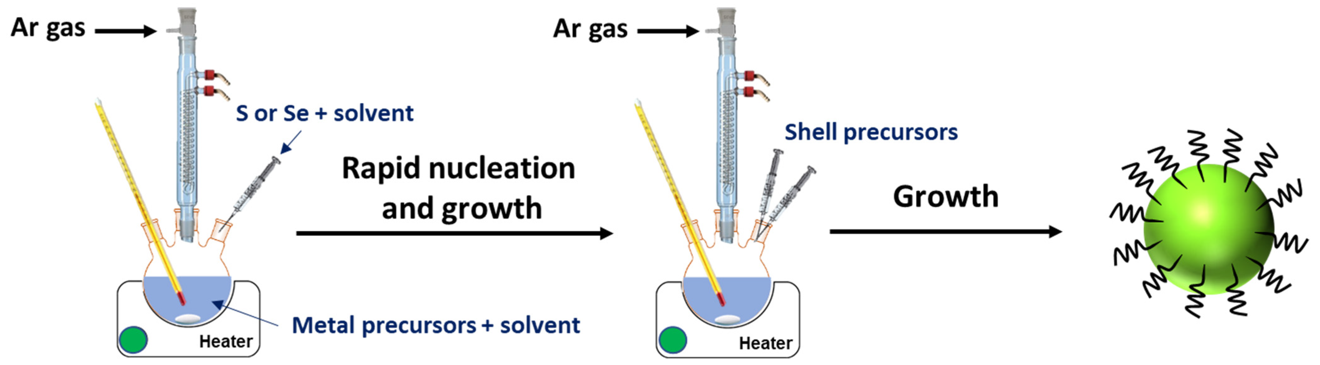
- The “hot-injection method”, which is the most commonly used [20,32]. The synthesis usually begins with the injection of the S (or Se or Te) precursor into a hot solution of the metal precursors, which causes the fast formation of nuclei and therefore good control of the growth of the nanocrystals (Figure 2). The growth of QDs via Ostwald ripening can be conducted at a lower temperature, so as not to generate new nuclei. This process allows for the production of high-quality and nearly monodisperse nanocrystals and is well-suited for the preparation of core/shell QDs.
- -
- The “non-injection” method involves the mixing of precursors followed by heating at a specific temperature at which the decomposition of precursors takes place and produces nanocrystals [33,34]. This method allows for a relatively good control of the nucleation and of the growth of the dots and thus of their average size and composition.
- -
- Single-source thermal decomposition usually involves the mixing of precursors (for example, copper and indium diethyldithiocarbamate or the (PPh3)2CuIn(SEt)4 complex) in OAm followed by their heating at a high temperature to break down the precursors into Cu+, In3+ and S2−, thus allowing for the nucleation of CuInS2 QDs followed by their growth [35,36]. Single-source thermal decomposition is the easiest method to produce QDs, but it does not allow for precise control over QD composition and therefore usually does not lead to high-quality nanocrystals.
- -
- Aqueous synthesis is less developed for the synthesis of I-III-VI2 QDs. It usually involves the injection of an S2− or Se2− precursor into an aqueous solution containing the metal precursors and the hydrophilic ligand (3-mercaptopropionic acid, glutathione, cysteine, …), followed by heating (reflux, hydrothermal, microwave, …) [14]. This method has many advantages, including a low cost and the use of water as a solvent, and allows for the production of QDs dispersible in water, which avoids a ligand exchange or an encapsulation in amphiphilic polymers for biological applications. However, the quality of QDs prepared in the aqueous phase is generally much lower than those produced in organic solvent, which limits their use in many applications. Note, however, that some of the best QDs prepared in the aqueous phase were obtained using microwave-assisted synthesis due to the volumetric heating that allows reactions to proceed faster compared to conventional hydrothermal synthesis [37,38].
4. I-III-VI2 QDs and Derivatives: Synthesis and PV Applications
- -
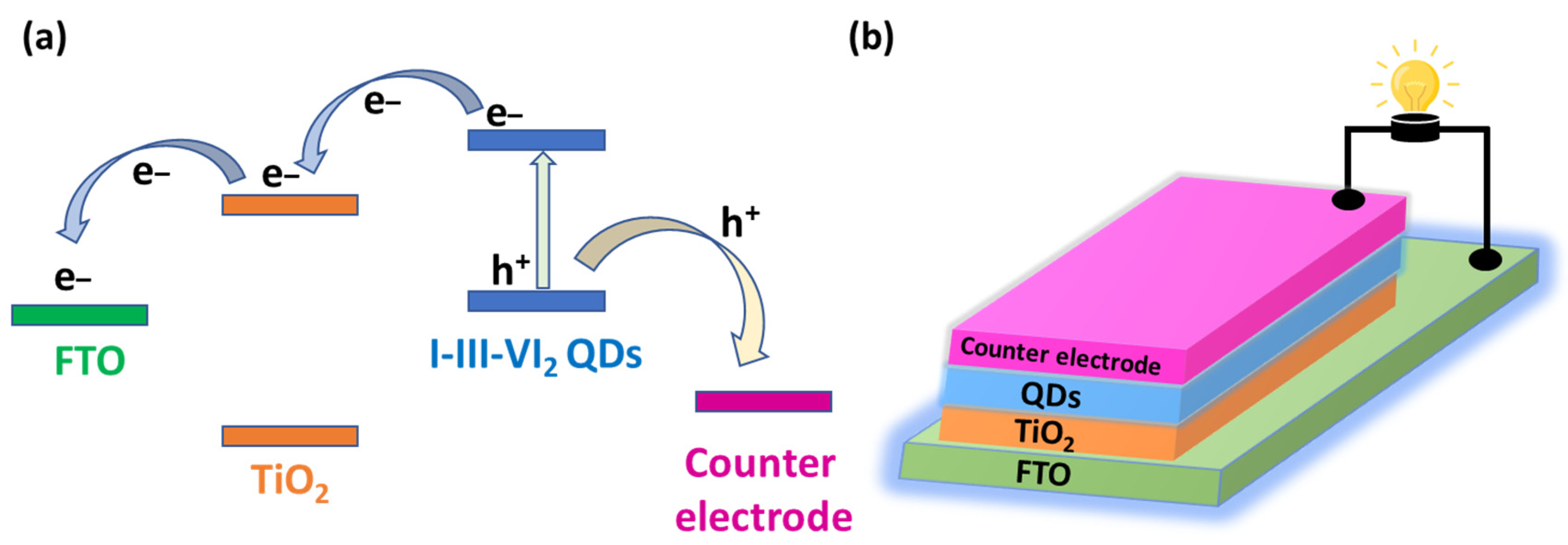
- QDs should exhibit a narrow bandgap, allowing for the harvesting of light in the visible and NIR regions.
- -
- The CB energy of QDs should be high to efficiently extract and transfer photogenerated electrons from QDs to TiO2. A large difference in energy between the CB of QDs and that of TiO2 promotes a fast extraction rate of photo-generated electrons.
- -
- The density of defect trap states, especially deep-level trap states, should be low, as these defects will not only cause a quenching of photoexcited electrons before their transfer to TiO2 but also a back transfer of these electrons from TiO2, which causes the charge recombination loss.
4.1. Cu-In-Se-Te (CISeTe) QDs
4.2. Ag-In-Zn-Te (AIZTe) QDs
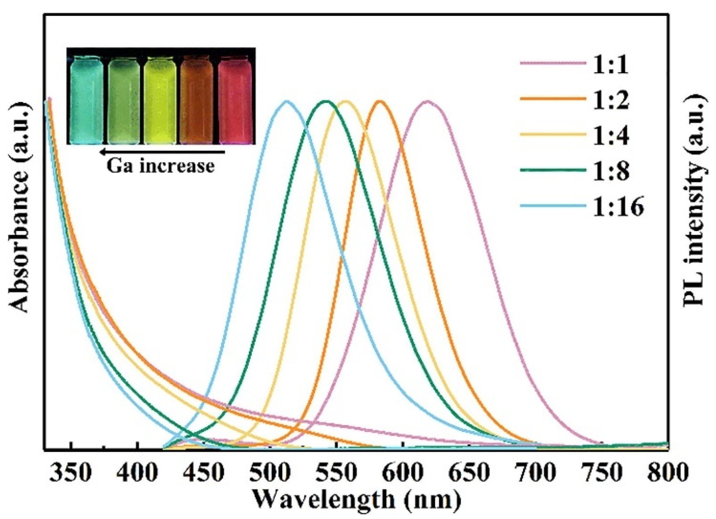
4.3. Cu-In-Ga-S (CIGS) and Cu-In-Ga-Zn-S (CIGZS) QDs
4.4. Cu-In-Ga-Se (CIGSe) and Cu-In-Ga-Se-S (CIGSSe) QDs
4.5. Ag-Ga-In-S (AIGS) QDs
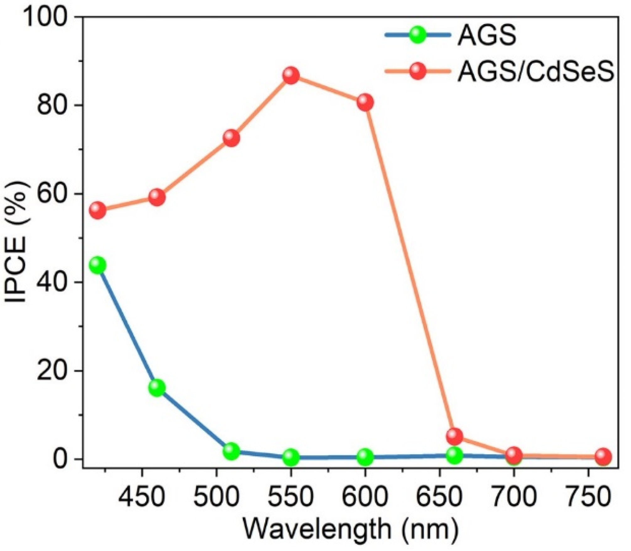
4.6. Ag-Ga-S(Se) (AGS(Se)) and Ag-Ga-Zn-S(Se) (AGZS(Se)) QDs
4.7. Ag-In-Ga-Se (AIGSe) QDs
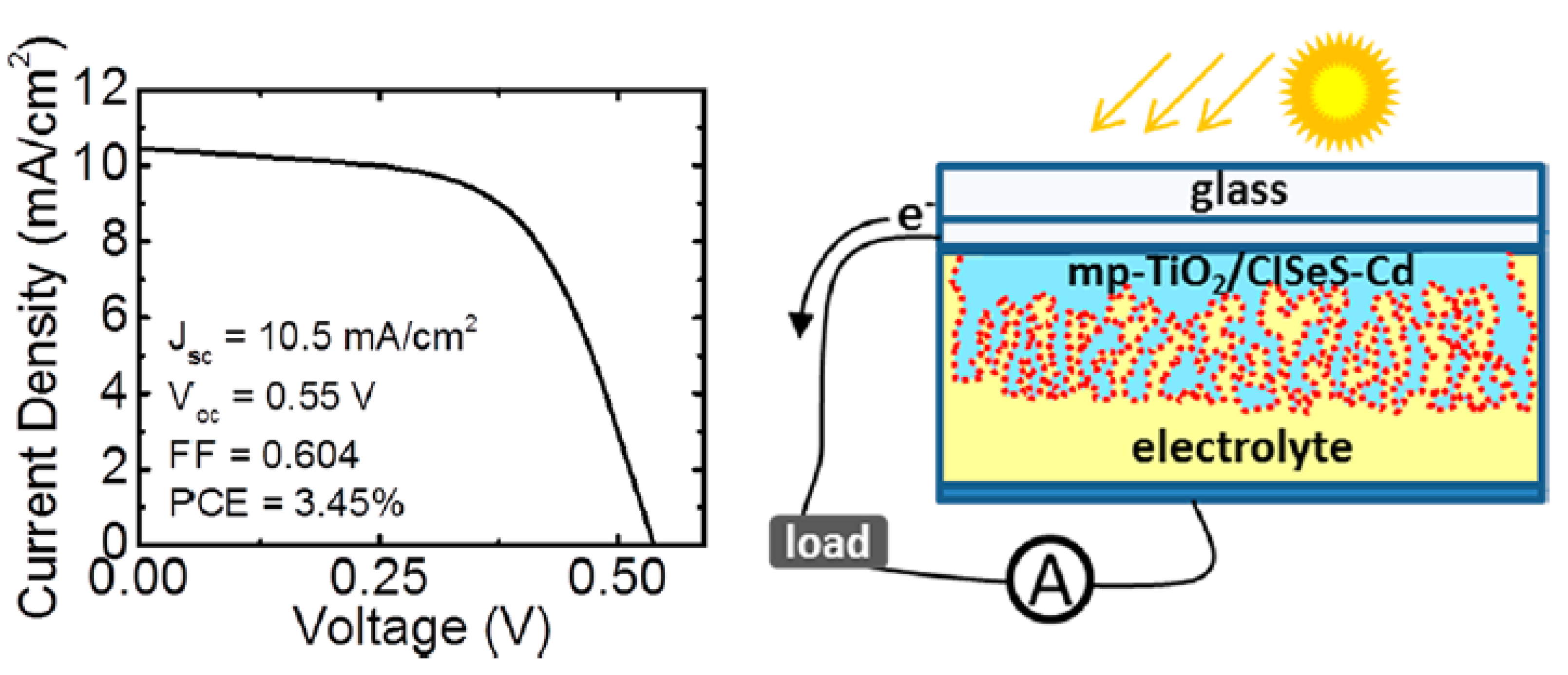
4.8. Cu-In-Se-S (CISeS) and Cu-In-Zn-Se-S (CIZSeS)QDs
4.9. Ag-Cu-In-S (ACIS) QDs
4.10. Ag-Cu-In-Se (ACISe) QDs
4.11. Ag-Cu-Ga-Se (ACGSe) QDs
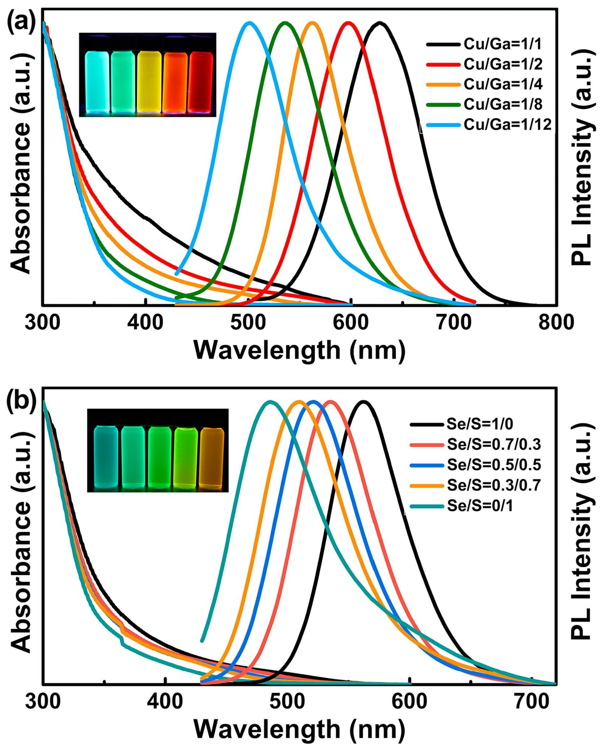
4.12. Cu-Ga-S(Se) and Cu-Ga-Zn-S(Se) QDs
4.13. Cu-Ga-Al-S QDs
4.14. CuAlS2 QDs
4.15. CuFeS2 QDs
5. Conclusions and Future Perspectives
- -
- Further improving the light-harvesting capacity of QDs through the development of new materials.
- -
- Decrease the density of defect trap states in these nanocrystals by tuning their chemical composition, for example, by cation and/or anion alloying, which is a key parameter for the optimal electron transfer in QDSSCs.
- -
- Develop doped I-III-VI2 QDs to enhance the lifetime of trapped electrons.
- -
- Increasing the QD loading on TiO2. This will allow us to decrease the thickness of the QDs-sensitized photoanode and thus improve the absorption of incident photons. A decrease in the thickness of the photoanode will lead to a short transportation path of photo-generated electrons and thus limit undesirable charge recombination. Moreover, if only a small part of the TiO2 film is not covered by the QDs, the probability of photogenerated electrons being trapped by the redox couple in the electrolyte will also decrease, and this will markedly improve the fill factor FF and thus the PCE of the QDSSCs.
- -
- Growing QDs on mesoporous TiO2 films using the successive ionic layer adsorption and reaction (SILAR) process to further enhance QD loading on TiO2 and thus the efficiency of the electron transfer from QDs to TiO2 [106].
- -
- Improving the band alignment and decreasing the surface state between QDs and TiO2 to decrease the recombination rate at the interface.
- -
- Gaining better knowledge of the interface charge-transfer processes not only between the TiO2 film and QDs sensitizers but also at the counter electrode.
- -
Author Contributions
Funding
Conflicts of Interest
References
- Bera, D.; Qian, L.; Tseng, T.-K.; Holloway, P.H. Quantum Dots and Their Multimodal Applications: A Review. Materials 2010, 3, 2260–2345. [Google Scholar]
- Jamieson, T.; Bakhshi, R.; Petrova, D.; Pocock, R.; Imani, M.; Seifalian, A.M. Biological applications of quantum dots. Biomaterials 2007, 28, 4717–4732. [Google Scholar] [CrossRef] [PubMed]
- Wagner, A.M.; Knipe, J.M.; Orive, G.; Peppas, N.A. Quantum dots in biomedical applications. Acta Biomater. 2019, 94, 44–63. [Google Scholar]
- Moon, H.; Lee, C.; Lee, W.; Kim, J.; Chae, H. Stability of Quantum Dots, Quantum Dot Films, and Quantum Dot Light-Emitting Diodes for Display Applications. Adv. Mater. 2019, 31, 1804284. [Google Scholar]
- Jang, E.; Jang, H. Quantum Dot Light-Emitting Diodes. Chem. Rev. 2023, 123, 4663–4692. [Google Scholar]
- Kovalenko, M. Opportunities and challenges for quantum dot photovoltaics. Nature Nanotech. 2015, 10, 994–997. [Google Scholar]
- Duan, L.; Hu, L.; Guan, X.; Lin, C.-H.; Chu, D.; Huang, S.; Liu, X.; Yuan, J.; Wu, T. Quantum Dots for Photovoltaics: A Tale of Two Materials. Adv. Energy Mater. 2021, 11, 2100354. [Google Scholar]
- Zrazhevskiy, P.; Sena, M.; Gao, X. Designing multifunctional quantum dots for bioimaging, detection, and drug delivery. Chem. Soc. Rev. 2010, 39, 4326–4354. [Google Scholar]
- Zebibula, A.; Alifu, N.; Xia, L.; Sun, C.; Yu, X.; Xue, D.; Liu, L.; Li, G.; Qian, J. Ultrastable and Biocompatible NIR-II Quantum Dots for Functional Bioimaging. Adv. Func. Mater. 2018, 28, 1703451. [Google Scholar]
- Liu, N.; Tang, M. Toxicity of different types of quantum dots to mammalian cells in vitro: An update review. J. Hazard. Mater. 2020, 399, 122606. [Google Scholar]
- Michalska, M.; Aboulaich, A.; Medjahdi, G.; Mahiou, R.; Jurga, S.; Schneider, R. Amine ligands control of the optical properties and the shape of thermally grown core/shell CuInS2/ZnS quantum dots. J. Alloys Compd. 2015, 645, 184–192. [Google Scholar] [CrossRef]
- Michalska, M.; Florczak, A.; Dams-Kozlowska, H.; Gapinski, J.; Jurga, S.; Schneider, R. Peptide-functionalized ZCIS QDs as fluorescent nanoprobe for targeted HER2-positive breast cancer cells imaging. Acta Biomater. 2016, 35, 293–304. [Google Scholar] [CrossRef] [PubMed]
- Galiyeva, P.; Alem, H.; Rinnert, H.; Balan, L.; Blanchard, S.; Medjahdi, G.; Uralbekov, B.; Schneider, R. Highly fluorescent, color tunable and magnetic quaternary Ag–In–Mn–Zn–S quantum dots. Inorg. Chem. Front. 2019, 6, 1422–1431. [Google Scholar]
- Mrad, M.; Ben Chaabane, T.; Rinnert, H.; Balan, L.; Jasniewski, J.; Medjahdi, G.; Schneider, R. Aqueous Synthesis for Highly Emissive 3-Mercaptopropionic Acid-Capped AIZS Quantum Dots. Inorg. Chem. 2020, 59, 6220–6231. [Google Scholar] [PubMed]
- Galiyeva, P.; Rinnert, H.; Bouguet-Bonnet, S.; Leclerc, S.; Balan, L.; Alem, H.; Blanchard, S.; Jasniewski, J.; Medjahdi, G.; Uralbekov, B.; et al. Mn-Doped Quinary Ag–In–Ga–Zn–S Quantum Dots for Dual-Modal Imaging. ACS Omega 2021, 6, 33100–33110. [Google Scholar] [CrossRef]
- Mrad, M.; Chouchene, B.; Ben Chaabane, T.; Gries, T.; Medjahdi, G.; Balan, L.; Schneider, R. Heterostructured Photocatalysts Associating ZnO Nanorods and Ag-In-Zn-S Quantum Dots for the Visible Light-Driven Photocatalytic Degradation of the Acid Orange 7 Dye. Catalysts 2022, 12, 1585. [Google Scholar]
- Fan, F.-J.; Wua, L.; Yu, S.-H. Energetic I–III–VI2 and I2–II–IV–VI4 nanocrystals: Synthesis, photovoltaic and thermoelectric applications. Energy Environ. Sci. 2014, 7, 190–208. [Google Scholar]
- Du, J.; Du, Z.; Hu, J.-S.; Pan, Z.; Shen, Q.; Sun, J.; Long, D.; Dong, H.; Sun, L.; Zhong, X.; et al. Zn–Cu–In–Se Quantum Dot Solar Cells with a Certified Power Conversion Efficiency of 11.6%. J. Am. Chem. Soc. 2016, 138, 4201–4209. [Google Scholar] [CrossRef]
- Yarema, O.; Yarema, M.; Wood, V. Tuning the Composition of Multicomponent Semiconductor Nanocrystals: The case of I-III-VI Materials. Chem. Mater. 2018, 30, 1446–1461. [Google Scholar]
- Jain, S.; Bharti, S.; Kaur Bhullar, G.; Tripathi, S.K. I-III-VI core/shell QDs: Synthesis, characterizations and applications. J. Lumin. 2020, 219, 116912. [Google Scholar]
- Piao, Z.; Yang, D.; Cui, Z.; He, H.; Mei, S.; Lu, H.; Fu, Z.; Wang, L.; Zhang, W.; Guo, R. Recent Advances in Metal Chalcogenide Quantum Dots: From Material Design to Biomedical Applications. Adv. Funct. Mater. 2022, 32, 2207662. [Google Scholar] [CrossRef]
- Wei, J.; Hu, Z.; Zhou, W.; Lu, H.; Zhang, W.; Guo, R. Color-converted white light-emitting diodes based on I-III-VI quantum dots: Package strategies and stability promotion. Appl. Mater. Today 2022, 29, 101585. [Google Scholar] [CrossRef]
- Yang, L.; Zhang, S.; Xu, B.; Jiang, J.; Cai, B.; Lv, X.; Zou, Y.; Fan, Z.; Yang, H.; Zeng, H. I-III-VI Quantum Dots and Derivatives: Design, Synthesis and Properties for Light-Emitting Diodes. Nano Lett. 2023, 23, 2443–2453. [Google Scholar] [CrossRef] [PubMed]
- Torimoto, T.; Kameyama, T.; Uematsu, T.; Kuwabata, S. Controlling optical properties and electronic energy structure of I-III-VI semiconductor quantum dots for improving their photofunctions. J. Photochem. Photobiol. C Photochem. Rev. 2023, 54, 100569. [Google Scholar] [CrossRef]
- Hamanaka, Y.; Ogawa, T.; Tsuzuki, M.; Kuzuya, T. Photoluminescence Properties and Its Origin of AgInS2 Quantum Dots with Chalcopyrite Structure. J. Phys. Chem. C 2011, 115, 1786–1792. [Google Scholar] [CrossRef]
- Kobosko, S.M.; Kamat, P.V. Indium-rich AgInS2-ZnS Quantum Dots-Ag/Zn-Dependent Photophysics and Photovoltaics. J. Phys. Chem. C 2018, 122, 14336–14344. [Google Scholar] [CrossRef]
- Hamanaka, Y.; Ozawa, K.; Kuzuya, T. Enhancement of Donor-Acceptor Pair Emissions in Colloidal AgInS2 Quantum Dots with High Concentrations of Defects. J. Phys. Chem. C 2014, 118, 14562–14568. [Google Scholar] [CrossRef]
- Jagadeeswara Rao, M.; Shibata, T.; Chattopadhyay, S.; Nag, A. Origin of Photoluminescence and XAFS Study of (ZnS)1−x(AgInS2)x Nanocrystals. J. Phys. Chem. Lett. 2014, 5, 167–173. [Google Scholar]
- Zang, H.; Li, H.; Makarov, N.S.; Velizhanin, K.A.; Wu, K.; Park, Y.-S.; Klimov, V.I. Thick-Shell CuInS2/ZnS Quantum Dots with Suppressed “Blinking” and Narrow Single-Particle Emission Line Widths. Nano Lett. 2017, 17, 1787–1795. [Google Scholar] [CrossRef]
- Stroyuk, O.; Raevskaya, A.; Spranger, F.; Selyshchev, O.; Dzhagan, V.; Schulze, S.; Zahn, D.R.T.; Eychmüller, A. Origin and Dynamics of Highly Efficient Broadband Photoluminescence of Aqueous Glutathione-Capped Size-Selected Ag-In-S Quantum Dots. J. Phys. Chem. C 2018, 122, 13648–13658. [Google Scholar] [CrossRef]
- Knowles, K.E.; Nelson, H.D.; Kilburn, T.B.; Gamelin, D.R. Singlet–Triplet Splittings in the Luminescent Excited States of Colloidal Cu+:CdSe, Cu+:InP, and CuInS2 Nanocrystals: Charge-Transfer Configurations and Self-Trapped Excitons. J. Am. Chem. Soc. 2015, 137, 13138–13147. [Google Scholar] [CrossRef] [PubMed]
- Yoon, H.C.; Oh, J.H.; Ko, M.; Yoo, H.; Do, Y.R. Synthesis and Characterization of Green Zn−Ag−In−S and Red Zn−Cu−In−S Quantum Dots for Ultrahigh Color Quality of Down-Converted White LEDs. ACS Appl. Mater. Interfaces 2015, 7, 7342–7350. [Google Scholar] [CrossRef] [PubMed]
- Shen, F.; Que, W.; Liao, Y.; Yin, X. Photocatalytic Activity of TiO2 Nanoparticles Sensitized by CuInS2 Quantum Dots. Ind. Eng. Chem. Res. 2011, 50, 9131–9137. [Google Scholar] [CrossRef]
- Akdas, T.; Haderlein, M.; Walter, J.; Apeleo Zubiri, B.; Spiecker, E.; Peukert, W. Continuous synthesis of CuInS2 quantum dots. RSC Adv. 2017, 7, 10057–10063. [Google Scholar] [CrossRef]
- Galiyeva, P.; Rinnert, H.; Balan, L.; Alem, H.; Medjahdi, G.; Uralbekov, B.; Schneider, R. Single-source precursor synthesis of quinary AgInGaZnS QDs with tunable photoluminescence emission. Appl. Surf. Sci. 2021, 562, 150143. [Google Scholar] [CrossRef]
- Hollingsworth, J.A.; Banger, K.K.; Jin, M.H.-C.; Harris, J.D.; Cowen, J.E.; Bohannan, E.W.; Switzer, J.A.; Buhro, W.E.; Hepp, A.F. Single source precursors for fabrication of I–III–VI thin-film solar cells via spray CVD. Thin Solid. Films 2003, 431–432, 63–67. [Google Scholar] [CrossRef]
- Mei, S.; Zhu, J.; Yang, W.; Wei, X.; Zhang, W.; Chen, Q.; He, L.; Jiang, Y.; Guo, R. Tunable emission and morphology control of the Cu-In-S/ZnS quantum dots with dual stabilizer via microwave-assisted aqueous synthesis. J. Alloy. Compd. 2017, 729, 1–8. [Google Scholar] [CrossRef]
- Fitzmorris, R.C.; Oleksak, R.P.; Zhou, Z.; Mangum, B.D.; Kurtin, J.N.; Herman, G.S. Structural and optical characterization of CuInS2 quantum dots synthesized by microwave-assisted continuous flow methods. J. Nanopart. Res. 2015, 17, 319. [Google Scholar] [CrossRef]
- Jean, J.; Mahony, T.S.; Bozyigit, D.; Sponseller, M.; Holovsky, J.; Bawendi, M.; Bulovic, V. Radiative Efficiency Limit with Band Tailing Exceeds 30% for Quantum Dot Solar Cells. ACS Energy Lett. 2017, 2, 2616–2624. [Google Scholar] [CrossRef]
- Pan, Z.; Mora-Sero, I.; Shen, Q.; Zhang, H.; Li, Y.; Zhao, K.; Wang, J.; Zhong, X.; Bisquert, J. High-Efficiency “Green” Quantum Dot Solar Cell. J. Am. Chem. Soc. 2014, 136, 9203–9210. [Google Scholar] [CrossRef]
- Kim, S.; Kang, M.; Kim, S.; Heo, J.-H.; Hong Noh, J.; Im, S.H.; Il Seok, S.; Kim, S.W. Fabrication of CuInTe2 and CuInTe2–xSex Ternary Gradient Quantum Dots and Their Application to Solar Cells. ACS Nano 2013, 7, 4756–4763. [Google Scholar] [CrossRef] [PubMed]
- Buatong, N.; Tang, I.M.; Pon-On, W. Fabrication of solar cells made with CuInTe2−xSex quantum dots sensitized hierarchical TiO2 sphere having a CuS counter electrode: Dependence on the Te/Se ratio. Mater. Lett. 2017, 199, 41–45. [Google Scholar] [CrossRef]
- Kameyama, T.; Sugiura, K.; Ishigami, Y.; Takahisa, Y.; Susumu, K.; Tomoki, O.; Naoto, T.; Tsukasa, T. Rod-shaped Zn–Ag–In–Te nanocrystals with wavelength-tunable band-edge photoluminescence in the near-IR region. J. Mater. Chem. C 2018, 6, 2034–2042. [Google Scholar] [CrossRef]
- Li, J.; Guan, T.; Tu, D.; Lian, W.; Zhang, P.; Han, S.; Wen, F.; Chen, X. Highly efficient NIR-II luminescent I–III–VI semiconductor nanoprobes based on AgInTe2:Zn/ZnS nanocrystals. Chem. Commun. 2022, 58, 2204–2207. [Google Scholar] [CrossRef]
- Song, W.-S.; Kim, J.-H.; Lee, J.-H.; Lee, H.-S.; Do, Y.R.; Yang, H. Synthesis of color-tunable Cu–In–Ga–S solid solution quantum dots with high quantum yields for application to white light-emitting diodes. J. Mater. Chem. 2012, 22, 21901–21908. [Google Scholar] [CrossRef]
- Kim, J.-H.; Yang, H. White lighting device from composite films embedded with hydrophilic Cu(In, Ga)S2/ZnS and hydrophobic InP/ZnS quantum dots. Nanotechnology 2014, 25, 225601. [Google Scholar] [CrossRef]
- Kim, J.-H.; Lee, K.-H.; Jo, D.-Y.; Lee, Y.; Hwang, J.Y.; Yang, H. Cu-In-Ga-S quantum dot composition dependent device performance of electrically driven light-emitting diodes. Appl. Phys. Lett. 2014, 105, 133104. [Google Scholar] [CrossRef]
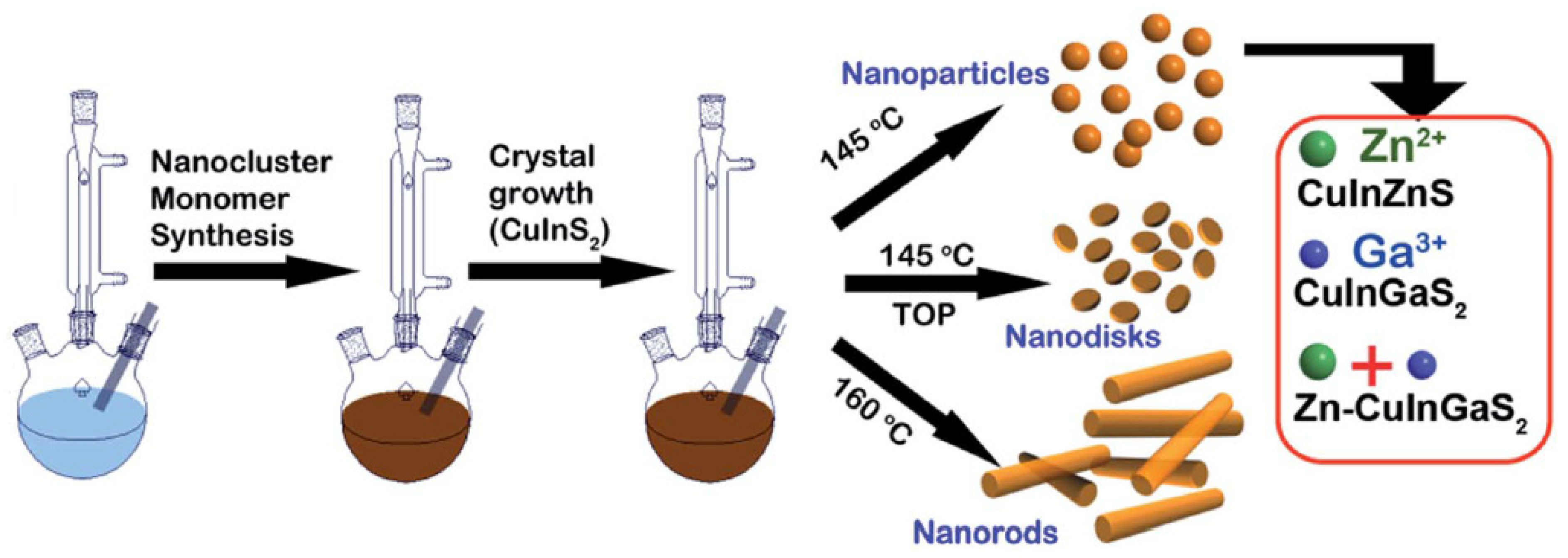
- Perera, S.D.; Zhang, H.; Ding, X.; Nelson, A.; Robinson, R.D. Nanocluster seed-mediated synthesis of CuInS2 quantum dots, nanodisks, nanorods, and doped Zn-CuInGaS2 quantum dots. J. Mater. Chem. C 2015, 3, 1044–1055. [Google Scholar] [CrossRef]
- Gugula, K.; Entrup, M.; Stegemann, L.; Seidel, S.; Pöttgen, R.; Strassert, C.A.; Bredol, M. Solid solution quantum dots with tunable Dual or ultrabroadband emission for LEDs. ACS Appl. Mater. Interfaces 2017, 9, 521–528. [Google Scholar] [CrossRef]
- Zhao, J.; Zhang, J.; Wang, W.; Wang, P.; Li, F.; Ren, D.; Si, H.; Sun, X.; Jia, F.; Hao, Y. Facile synthesis of CuInGaS2 quantum dot nanoparticles for bilayer-sensitized solar cells. Dalton Trans. 2014, 43, 16588–16592. [Google Scholar] [CrossRef]
- Chang, S.-H.; Chiang, M.-Y.; Chiang, C.C.; Yuan, F.W.; Chen, C.Y.; Chiu, B.C.; Kao, T.L.; Laic, C.H.; Tuan, H.-Y. Facile colloidal synthesis of quinary CuIn1-xGax(SySe1-y)2 (CIGSSe) nanocrystal inks with tunable band gaps for use in low-cost photovoltaics. Energy Environ. Sci. 2011, 4, 4929–4932. [Google Scholar] [CrossRef]
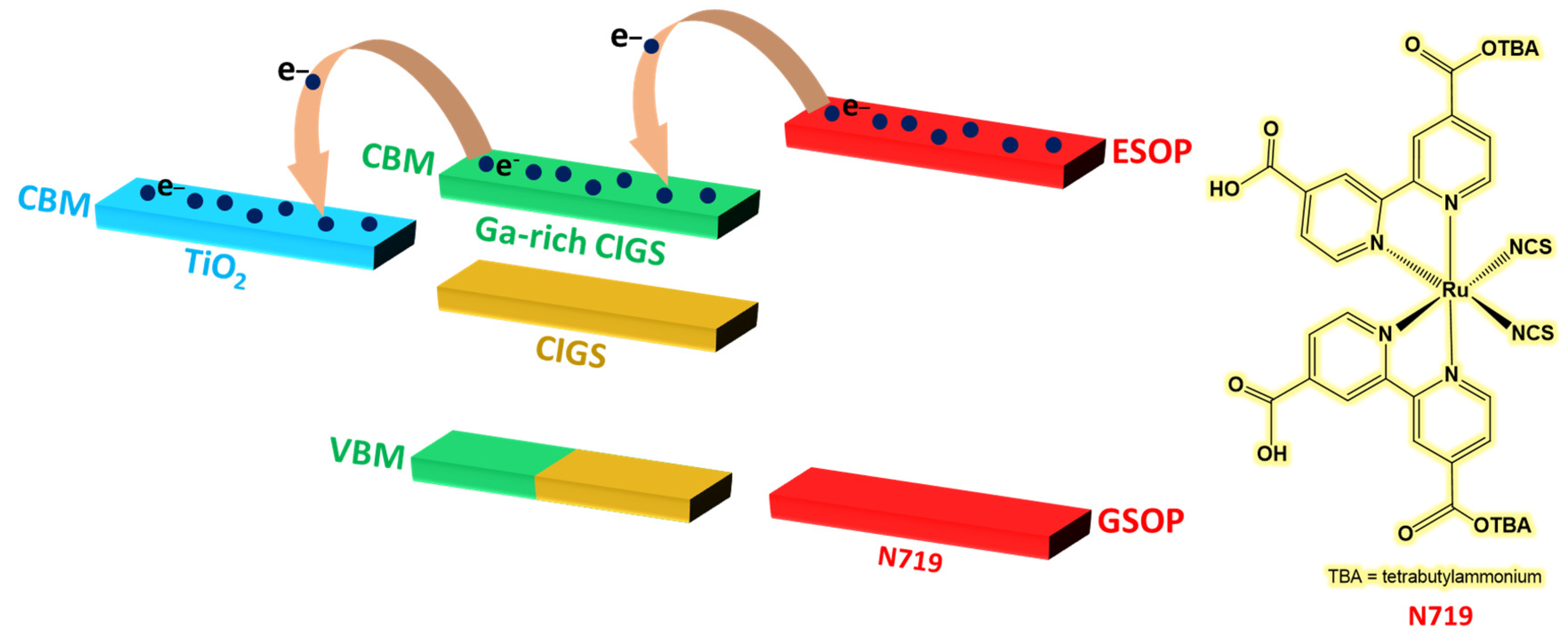
- Lin, C.-H.; Huang, K.P.; Ho, S.T.; Huang, M.W.; He, H., Jr. An energy-harvesting scheme utilizing Ga-rich CuIn(1−x)GaxSe2 quantum dots for dye-sensitized solar cells. Appl. Phys. Lett. 2012, 101, 123901. [Google Scholar] [CrossRef]
- Parc, J.-Y. One pot solvothermal synthesis of colloidal Cu(In1-xGax)Se2 (CIGS) quantum dots for solar cell applications. J. Alloys Compd. 2015, 629, 162–166. [Google Scholar] [CrossRef]
- Peng, W.; Du, J.; Pan, Z.; Nakazawa, N.; Sun, J.; Du, Z.; Shen, G.; Yu, J.; Hu, J.-S.; Shen, Q.; et al. Alloying strategy in Cu−In−Ga−Se quantum dots for high efficiency quantum dot sensitized solar cells. ACS Appl. Mater. Interfaces 2017, 9, 5328–5336. [Google Scholar] [CrossRef] [PubMed]
- Mubiayi, K.P.; Guilhermitti Neto, D.M.; Morais, A.; Pereira Nogueira, H.; de Almeida Santos, T.E.; Mazon, T.; Moloto, N.; Moloto, M.J.; Nei Freitas, J. Microwave assisted synthesis of CuInGaSe2 quantum dots and spray deposition of their composites with graphene oxide derivatives. Mater. Chem. Phys. 2020, 242, 122449. [Google Scholar] [CrossRef]
- Gonçalves, B.F.; LaGrow, A.P.; Pyrlin, S.; Owens-Baird, B.; Botelho, G.; Marques, L.S.A.; Ramos, M.M.D.; Kovnir, K.; Lanceros-Mendez, S.; Kolen’ko, Y. Large-scale synthesis of semiconducting Cu(In,Ga)Se2 nanoparticles for screen printing application. Nanomaterials 2021, 11, 1148. [Google Scholar] [CrossRef]
- Hoisang, W.; Uematsu, T.; Torimoto, T.; Kuwabata, S. Luminescent quaternary Ag(InxGa1−x)S2/GaSy core/shell quantum dots prepared using dithiocarbamate compounds and photoluminescence recovery via post treatment. Inorg. Chem. 2021, 60, 13101–13109. [Google Scholar] [CrossRef]
- Huang, G.; Huang, Y.; Liu, Z.; Wei, J.; Zhu, Q.; Jiang, G.; Jin, X.; Li, Q.; Li, F. White light-emitting diodes based on quaternary Ag–In-Ga-S quantum dots and their influences on melatonin suppression index. J. Lumin. 2021, 233, 117903. [Google Scholar] [CrossRef]
- Motomura, G.; Iwasaki, Y.; Kameyama, T.; Torimoto, T.; Uematsu, T.; Kuwabata, S.; Tsuzuki, T. Green Electroluminescence Generated by Band-edge Transition in Ag-In-Ga-S/GaSx Core/shell Quantum Dots. ITE Trans. MTA 2021, 9, 222–227. [Google Scholar]
- Watcharaporn, H.; Taro, U.; Tsukasa, T.; Susumu, K. Surface ligand chemistry on quaternary Ag(InxGa1−x)S2 semiconductor quantum dots for improving photoluminescence properties. Nanoscale Adv. 2022, 4, 849–857. [Google Scholar]
- Uematsu, T.; Tepakidareekul, M.; Hirano, T.; Torimoto, T.; Kuwabata, S.K. Facile high-yield synthesis of Ag−In−Ga−S quaternary quantum dots and coating with gallium sulfide shells for narrow band-edge emission. Chem. Mater. 2023, 35, 1094–1106. [Google Scholar] [CrossRef]
- Hu, Z.; Lu, H.; Zhou, W.; Wei, J.; Dai, H.; Hong Liu, H.; Xiong, Z.; Xie, F.; Zhang, W.; Guo, R. Aqueous synthesis of 79% efficient AgInGaS/ZnS quantum dots for extremely high color rendering white light-emitting diodes. J. Mater. Sci. Technol. 2023, 134, 189–196. [Google Scholar] [CrossRef]
- Zhange, W.-J.; Pan, C.Y.; Cao, F.; Wang, H.; Yang, X. Bright violet-to-aqua-emitting cadmium-free Ag-doped Zn–Ga–S quantum dots with high stability. Chem. Comm. 2018, 54, 4176–4179. [Google Scholar]
- Kim, J.-H.; Kim, B.-Y.; Jang, E.-P.; Yoon, S.-Y.; Kim, K.-H.; Do, Y.R.; Yang, H. Synthesis of widely emission-tunable Ag–Ga–S and its quaternary derivative quantum dots. Chem. Eng. J. 2018, 347, 791–797. [Google Scholar] [CrossRef]
- Tianyu, B.; Wang, X.; Dong, Y.; Xing, S.; Shi, Z.; Feng, S. One-pot synthesis of high-quality AgGaS2/ZnS-based photoluminescent nanocrystals with widely tunable band gap. Inorg. Chem. 2020, 59, 5975–5982. [Google Scholar]
- Xie, X.; Zhao, J.; Lin, O.; Yin, Z.; Li, X.; Zhang, Y.; Tang, A. Narrow-Bandwidth Blue-Emitting Ag–Ga–Zn–S Semiconductor Nanocrystals for Quantum-Dot Light-Emitting Diodes. J. Phys. Chem. Lett. 2022, 13, 11857–11863. [Google Scholar]
- Lu, H.X.; Liu, H.; Fu, Z.Z.; Chen, Y.Y.; Dai, H.Q.; Hu, Z.; Zhang, W.L.; Guo, R.Q. Rational design of AgGaS/ZnS/ZnS quantum dots with a near-unity photoluminescence quantum yield via double shelling scheme. J. Mater. Sci. Technol. 2024, 169, 235–242. [Google Scholar] [CrossRef]
- Li, X.; Tong, X.; Yue, S.; Liu, C.; Channa, A.I.; You, Y.; Wang, R.; Long, Z.; Zhang, Z.; Zhao, Z.; et al. Rational design of colloidal AgGaS2/CdSeS core/shell quantum dots for solar energy conversion and light detection. Nano Energy 2021, 89, 106392. [Google Scholar] [CrossRef]
- Kottayi, R.; Ilangovan, V.; Sittaramane, R. Wide light-harvesting AgZnGaS3 quantum dots as an efficient sensitizer for solar cells. Opt. Mater. 2022, 134, 113036. [Google Scholar] [CrossRef]
- Kottayi, R.; Ilangovan, V.; Sittaramane, R. Near-infrared photoactive Ag-Zn-Ga-S-Se quantum dots for high-performance quantum dot-sensitized solar cells. Beilstein J. Nanotechnol. 2022, 13, 1337–1344. [Google Scholar] [CrossRef]
- Azhniuk, Y.; Lopushanska, B.; Selyshchev, O.; Havryliuk, Y.; Pogodin, A.; Kokhan, O.; Ehm, A.; Lopushansky, V.; Studenyak, I.; Zahn, D.R.T. Synthesis and optical properties of Ag–Ga–S quantum dots. Phys. Status Solidi B 2022, 259, 2100349. [Google Scholar] [CrossRef]
- Kameyama, T.; Yamauchi, H.; Yamamoto, T.; Mizumaki, T.; Yukawa, H.; Yamamoto, M.; Ikeda, S.; Uematsu, T.; Baba, Y.; Kuwabata, S.; et al. Tailored Photoluminescence Properties of Ag(In,Ga)Se2 Quantum Dots for Near-Infrared In Vivo Imaging. ACS Appl. Nano Mater. 2020, 3, 3275–3287. [Google Scholar] [CrossRef]
- Rismaningsih, N.; Yamauchi, H.; Kameyama, T.; Yamamoto, T.; Morita, S.; Yukawa, H.; Uematsu, T.; Baba, Y.; Kuwabata, S.; Torimoto, T. Photoluminescence properties of quinary Ag–(In,Ga)–(S,Se) quantum dots with a gradient alloy structure for in vivo bioimaging. J. Mater. Chem. C 2021, 9, 12791. [Google Scholar] [CrossRef]
- McDaniel, H.; Fuke, N.; Pietryga, M.J.; Klimov, I.V. Engineered CuInSexS2−x Quantum Dots for Sensitized Solar Cells. J. Phys. Chem. Lett. 2013, 4, 355–361. [Google Scholar] [CrossRef]
- McDaniel, H.; Koposov, Y.A.; Draguta, S.; Pietryga, M.J.; Klimov, I.V. Simple yet Versatile Synthesis of CuInSexS2−x Quantum Dots for Sunlight Harvesting. J. Phys. Chem. C 2014, 118, 16987–16994. [Google Scholar] [CrossRef]
- Song, H.; Lin, Y.; Zhou, M.; Rao, H.; Pan, Z.; Zhong, X. Zn-Cu-In-S-Se Quinary “Green” Alloyed Quantum-dot-sensitized Solar Cells with a Certified Efficiency of 14.4%. Angew. Chem. Int. Ed. 2021, 60, 6137–6144. [Google Scholar] [CrossRef] [PubMed]
- Song, H.; Lin, Y.; Zhang, Z.; Rao, H.; Wang, W.; Fang, Y.; Pan, Z.; Zhong, X. Improving the Efficiency of Quantum Dot Sensitized Solar Cells beyond 15% via Secondary Deposition. J. Am. Chem. Soc. 2021, 143, 4790–4800. [Google Scholar] [CrossRef]
- Hwang, D.-K.; Jeong Jo, H.; Kim, D.-H.; Jin Lee, E.; Chang, R.P.H. Hybrid dual-stage flow synthesis of eco-friendly ZnCuInSSe quantum dots for solar cells: Improvement in efficiency using inorganic ligand exchange. J. Power Sources 2023, 555, 232344. [Google Scholar] [CrossRef]
- Raievska, O.; Stroyuk, O.; Azhniuk, Y.; Solonenko, D.; Barabash, A.; Brabec, C.J.; Zahn, D.R.T. Composition-dependent optical band bowing, vibrational, and photochemical behavior of aqueous glutathione-capped (Cu, Ag)–In–S quantum dots. J. Phys. Chem. C 2020, 124, 19375–19388. [Google Scholar] [CrossRef]
- Stroyuk, O.; Raievska, O.; Langner, S.; Kupfer, C.; Barabash, A.; Solonenko, D.; Azhniuk, Y.; Hauch, J.; Osvet, A.; Batentschuk, M.; et al. High-throughput robotic synthesis and photoluminescence characterization of aqueous multinary copper–silver indium chalcogenide quantum dots. Part. Part. Syst. Charact. 2021, 38, 2100169. [Google Scholar] [CrossRef]
- Raevskaya, A.; Rozovik, O.; Novikova, A.; Selyshchev, O.; Stroyuk, O.; Dzhagan, V.; Goryacheva, I.; Gaponik, N.; Zahn, D.R.T.; Eychmüller, A. Luminescence and photoelectrochemical properties of size-selected aqueous copper-doped Ag–In–S quantum dots. RSC Adv. 2018, 8, 7550–7557. [Google Scholar] [CrossRef] [PubMed]
- Kottayi, R.; Panneerselvam, P.; Murugadoss, V.; Sitta-ramane, R.; Angaiah, S. Cu2AgInSe4 QDs sensitized electrospun porous TiO2 nanofibers as an efficient photoanode for quantum dot sensitized solar cells. Solar Energy 2020, 199, 317–325. [Google Scholar] [CrossRef]
- Wei, J.; Hu, Z.; Zhou, W.; Qiu, Y.; Dai, H.; Chen, Y.; Zhongjie Cui, Z.; Liu, S.; He, H.; Zhang, W.; et al. Emission tuning of highly efficient quaternary Ag-Cu-Ga-Se/ZnSe quantum dots for white light-emitting diodes. J. Colloid. Interface Sci. 2021, 602, 307–315. [Google Scholar] [CrossRef] [PubMed]
- Kim, B.-Y.; Kim, J.-H.; Lee, K.-H.; Jang, E.-P.; Han, C.-Y.; Jo, J.-H.; Jang, H.S.; Yang, H. Synthesis of highly efficient azure-to-blue-emitting Zn–Cu–Ga–S quantum dots. Chem. Commun. 2017, 53, 4088–4091. [Google Scholar] [CrossRef] [PubMed]
- Kim, J.-H.; Kim, K.-H.; Yoon, S.Y.; Kim, Y.; Lee, S.-H.; Kim, H.-S.; Yang, H. Tunable Emission of Bluish Zn−Cu−Ga−S Quantum Dots by Mn Doping and Their Electroluminescence. ACS Appl. Mater. Interfaces 2019, 11, 8250–8257. [Google Scholar] [CrossRef] [PubMed]
- Li, M.; Wei, X.; Mei, S.; Cui, Z.; Fan, Y.; Yang, B.; Wen, Z.; Xiong, Z.; Wang, L.; Xie, F.; et al. Highly luminescent copper gallium selenium based multicomponent quantum dots: Formation process and tunable white-light emission. Appl. Surf. Sci. 2021, 538, 147907. [Google Scholar] [CrossRef]
- Hu, Z.M.; Fei, G.T.; Li De Zhang, L.D. Synthesis of green-to-red-emitting Cu-Ga-S/ZnS core/shell quantum dots for application in white light-emitting diodes. J. Lumin. 2019, 208, 18–23. [Google Scholar] [CrossRef]
- Hase, S.; Iso, Y.; Isobe, T. Bandgap-tuned fluorescent CuGaS2/ZnS core/shell quantum dots for photovoltaic applications. J. Mater. Chem. C 2022, 10, 3523–3530. [Google Scholar] [CrossRef]
- You, Y.; Tong, X.; Channa, A.I.; Li, X.; Liu, C.; Ye, H.; Wang, Z. Tailoring the optoelectronic properties of eco-friendly CuGaS2/ZnSe core/shell quantum dots for boosted photoelectrochemical solar hydrogen production. EcoMat 2022, 4, e12206. [Google Scholar] [CrossRef]
- Mei, S.; Zhang, G.; Yang, W.; Wei, X.; Zhang, W.; Zhu, J.; Guo, R. A facile route for highly efficient color-tunable Cu-Ga-Se/ZnSe quantum dots. Appl. Surf. Sci. 2018, 456, 876–881. [Google Scholar] [CrossRef]
- Yoon, S.-K.; Kim, Y.-H.; Jo, D.-Y.; Jo, J.-H.; Lee, S.-H.; Kim, H.-M.; Kim, Y.; Kim, S.-K.; Yang, H. Efficient synthesis of multinary Zn-Cu-Ga-Se1-xSx quantum dots as full visible-covering emitters and their tricolored white electroluminescence. Chem. Engineer. J. 2021, 410, 128426. [Google Scholar] [CrossRef]
- You, Y.; Tong, X.; Imran Channa, A.; Zhi, H.; Cai, M.; Zhao, H.; Xia, L.; Liu, G.; Zhao, H.; Wang, Z. High-efficiency luminescent solar concentrators based on Composition-tunable Eco-friendly Core/shell quantum dots. Chem. Engineer. J. 2023, 452, 139490. [Google Scholar] [CrossRef]
- Bhattacharyya, B.; Pandit, T.; Rajasekar, G.P.; Pandey, A. Optical Transparency Enabled by Anomalous Stokes Shift in Visible Light-Emitting CuAlS2-Based Quantum Dots. J. Phys. Chem. Lett. 2018, 9, 4451–4456. [Google Scholar] [CrossRef] [PubMed]
- Mukherjee, A.; Dutta, P.; Bhattacharyya, B.; Rajasekar, G.P.; Simlandy, A.K.; Pandey, A. Ultrafast spectroscopic investigation of the artificial photosynthetic activity of CuAlS2/ZnS quantum dots. Nano Select 2021, 2, 958–966. [Google Scholar] [CrossRef]
- Baum, F.; Pretto, T.; Almeida Gouvea, R.; Leite Santos, M.J. Design of Experiments and Theoretical Investigation for Photoluminescence Optimization of Copper Aluminum Sulfide Nanoparticles through Controlling Crystalline Defects. Cryst. Growth Des. 2022, 22, 3669–3679. [Google Scholar] [CrossRef]
- Bhattacharyya, B.; Pandey, A. CuFeS2 Quantum Dots and Highly Luminescent CuFeS2 Based Core/Shell Structures: Synthesis, Tunability, and Photophysics. J. Am. Chem. Soc. 2016, 138, 10207–10213. [Google Scholar] [CrossRef]
- Yan, T.; Li, Y.; Song, X.; Wang, J.; Xie, Z.; Deng, D. Highly luminescent NIR-emitting CuFeS2/ZnS core/shell quantum dots for optical imaging of inflamed tissue. J. Mater. Chem. C 2019, 7, 7279–7287. [Google Scholar] [CrossRef]
- Wu, N.; Liu, X.; Zeng, M.; Gao, J.; Lu, X.; Zeng, Z.; Zheng, Y. Controllable synthesis of novel luminescent CuFeS2 quantum dots with magnetic properties and cation sensing features. J. Nanopart. Res. 2019, 21, 268. [Google Scholar] [CrossRef]
- Wu, N.; Li, Y.; Zeng, M.; Gao, J.; Tang, Y.; Zeng, Z.; Zheng, Y. Design of chalcopyrite-type CuFeSe2 nanocrystals: Microstructure, magnetism, photoluminescence and sensing performances. J. Solid. State Chem. 2019, 271, 292–297. [Google Scholar] [CrossRef]
- Yang, A.; Huangfu, X.; Liu, L.; Luo, W.; Zhao, W.; Yin, J. Electrochemiluminescence immunosensor based on signal probe CuFeS2 quantum dots for ultrasensitive detection of cyclin D1. J. Electroanal. Chem. 2020, 871, 114269. [Google Scholar] [CrossRef]
- Guo, P.; Song, H.; Liu, Y.; Wang, C. CuFeS2 Quantum Dots Anchored in Carbon Frame: Superior Lithium Storage Performance and the Study of Electrochemical Mechanism. ACS Appl. Mater. Interfaces 2017, 9, 31752–31762. [Google Scholar] [CrossRef] [PubMed]
- Ge, Q.; Feng, X.; Wang, R.; Zheng, R.; Luo, S.; Duan, L.; Ji, Y.; Lin, J.; Chen, H. Mixed Redox-Couple-Involved Chalcopyrite Phase CuFeS2 Quantum Dots for Highly Efficient Cr(VI) Removal. Environ. Sci. Technol. 2020, 54, 8022–8031. [Google Scholar] [CrossRef] [PubMed]
- Shangguan, Y.; Zhou, Y.; Zheng, R.; Feng, X.; Ge, Q.; Wang, R.; Dazhong, Y.; Wei, W.; Wu, X.; Lin, J.; et al. Bandgap engineering of tetragonal phase CuFeS2 quantum dots via mixed-valence single-atomic Ag decoration for synergistic Cr(VI) reduction and RhB degradation. Chin. Chem. Lett. 2021, 32, 3450–3456. [Google Scholar] [CrossRef]
- Shangguan, Y.; Zheng, R.; Ge, Q.; Feng, X.; Wang, R.; Zhou, Y.; Luo, S.; Duan, L.; Lin, J.; Chen, H. Interfacial engineering of CuFeS2 quantum dots via platinum decoration with enhanced Cr(VI) reduction dynamics under UV-Vis-NIR radiation. J. Hazard. Mater. 2022, 421, 126701. [Google Scholar] [CrossRef]
- Naveena, D.; Thirumalaisamy, L.; Dhanabal, R.; Sethuraman, K.; Chandra Bose, A. Tuning the properties of the CuAl(1-x)FexS2 Thin Films as a Potential Absorber for Solar Cell Application. ACS Appl. Energy Mater. 2020, 3, 10550–10559. [Google Scholar] [CrossRef]
- Mohamed Mustakim, N.S.; Ahamefula Ubani, C.; Sepeai, S.; Ahmad Ludin, N.; Mat Teridi, M.A.; Adib Ibrahim, M. Quantum dots processed by SILAR for solar cell applications. Solar Energy 2018, 163, 256–270. [Google Scholar] [CrossRef]
- Wang, Y.-q.; Rui, Y.-c.; Zhang, Q.-h.; Li, Y.-g.; Wang, H.-z. A Facile in Situ Synthesis Route for CuInS2 Quantum-Dots/In2S3 Co-Sensitized Photoanodes with High Photoelectric Performance. ACS Appl. Mater. Interfaces 2013, 5, 11858–11864. [Google Scholar] [CrossRef]
- Chang, J.Y.; Lin, J.M.; Su, L.F.; Chang, C.F. Improved Performance of CuInS2 Quantum Dot-Sensitized Solar Cells Based on a Multilayered Architecture. ACS Appl. Mater. Interfaces 2013, 5, 8740–8752. [Google Scholar] [CrossRef]


| QDs | Jsc (mAcm−2) | VOC (mV) | FF (%) | PCE (%) | Ref. |
|---|---|---|---|---|---|
| CISeTe | 17.40 | 400 | 44 | 3.10 | [41] |
| CISeTe | 11.70 | 683 | 51 | 3.75 | [42] |
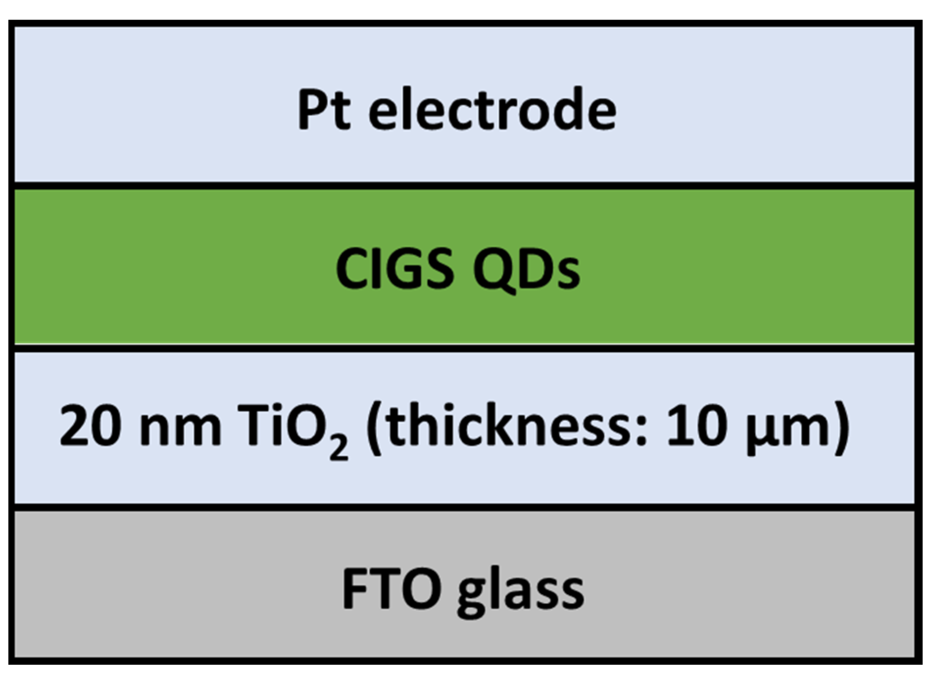
| TiO2@CIGS | 18.44 | 767 | 53 | 7.51 | [50] |
| CIGSeS | 13.96 | 260 | 28 | 1.02 | [51] |
| CIGSe | 15.27 | 762 | 69 | 8.02 | [52] |
| CIGSe | 0.24 | 432 | 54 | 0.05 | [53] |
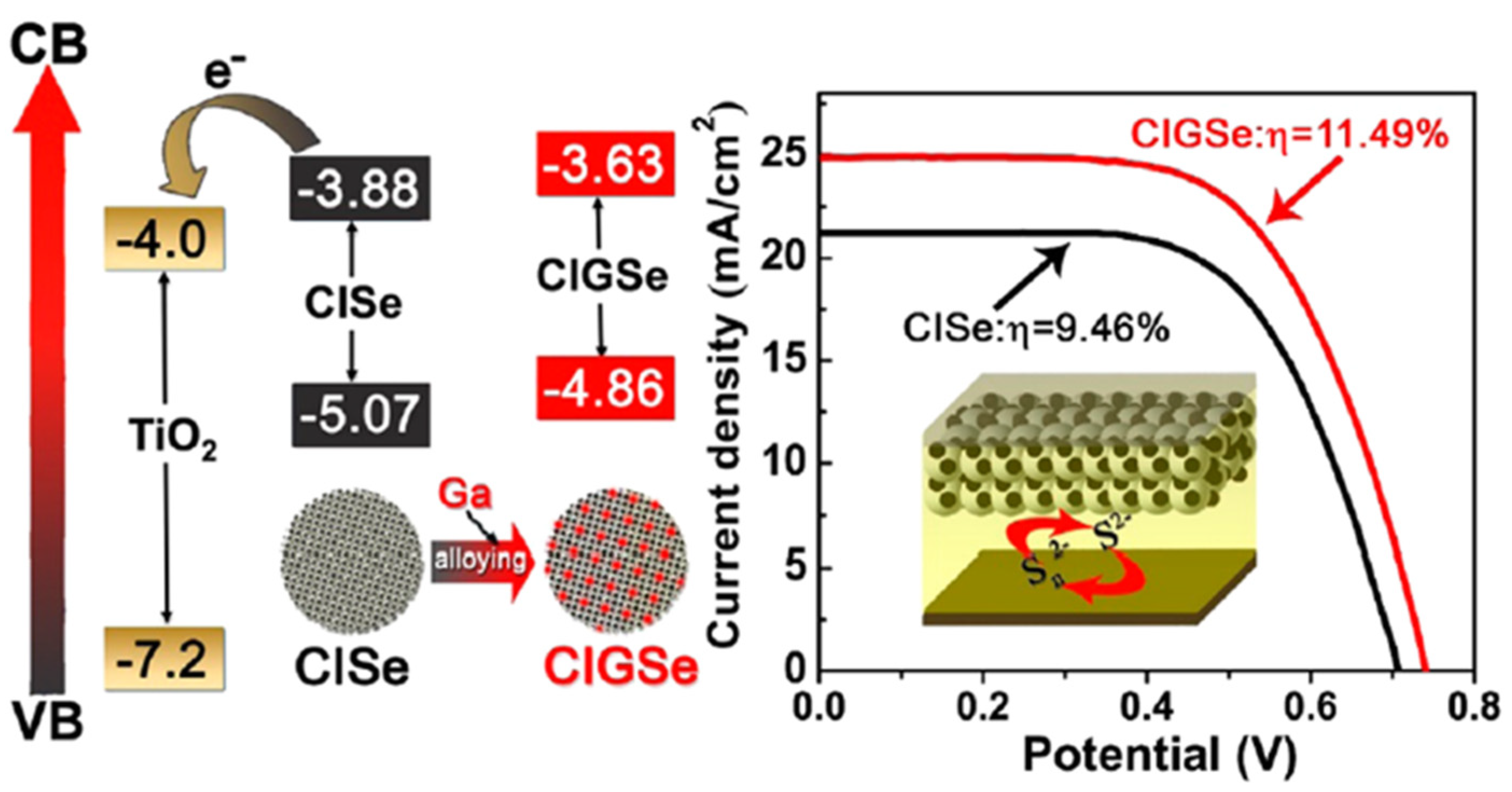
| CIGSe | 25.01 | 740 | 62 | 11.49 | [54] |
| CIGSe@rGO | 8.78 | 690 | 33 | 2.00 | [55] |
| AGZS | 12.31 | 510 | 62 | 3.81 | [69] |
| AGZSSe | 14.20 | 540 | 64 | 4.91 | [70] |
| CISeS | 10.50 | 550 | 80 | 3.45 | [74] |
| CIZSeS | 25.51 | 780 | 72 | 14.4 | [76] |
| CIZSeS | 26.30 | 802 | 71 | 15.20 | [77] |
| CIZSeS | 19.50 | 590 | 55 | 6.40 | [78] |
| ACISe | 12.86 | 520 | 63 | 4.24 | [82] |
| CGAS/ZnS | 11.49 | n.p. | n.p. | 4.29 | [92] |
| CuAl0.25Fe0.75S2 | 12.57 | 620 | 47 | 3.65 | [105] |
Disclaimer/Publisher’s Note: The statements, opinions and data contained in all publications are solely those of the individual author(s) and contributor(s) and not of MDPI and/or the editor(s). MDPI and/or the editor(s) disclaim responsibility for any injury to people or property resulting from any ideas, methods, instructions or products referred to in the content. |
© 2023 by the authors. Licensee MDPI, Basel, Switzerland. This article is an open access article distributed under the terms and conditions of the Creative Commons Attribution (CC BY) license (https://creativecommons.org/licenses/by/4.0/).
Share and Cite
Shishodia, S.; Chouchene, B.; Gries, T.; Schneider, R. Selected I-III-VI2 Semiconductors: Synthesis, Properties and Applications in Photovoltaic Cells. Nanomaterials 2023, 13, 2889. https://doi.org/10.3390/nano13212889
Shishodia S, Chouchene B, Gries T, Schneider R. Selected I-III-VI2 Semiconductors: Synthesis, Properties and Applications in Photovoltaic Cells. Nanomaterials. 2023; 13(21):2889. https://doi.org/10.3390/nano13212889
Chicago/Turabian StyleShishodia, Shubham, Bilel Chouchene, Thomas Gries, and Raphaël Schneider. 2023. "Selected I-III-VI2 Semiconductors: Synthesis, Properties and Applications in Photovoltaic Cells" Nanomaterials 13, no. 21: 2889. https://doi.org/10.3390/nano13212889
APA StyleShishodia, S., Chouchene, B., Gries, T., & Schneider, R. (2023). Selected I-III-VI2 Semiconductors: Synthesis, Properties and Applications in Photovoltaic Cells. Nanomaterials, 13(21), 2889. https://doi.org/10.3390/nano13212889